static aeroelastic analysis of a three-dimensional … · nasa technical memorandum 102231 static...
TRANSCRIPT
NASA Technical Memorandum 102231
Static Aeroelastic Analysisof a Three-DimensionalGeneric WingJohn A. Green, In Lee, and Hirokazu Miura
February 1990
National Aeronautics andSpace Administration
https://ntrs.nasa.gov/search.jsp?R=19900010771 2018-06-19T17:51:03+00:00Z


NASATechnical Memorandum 102231
Static Aeroelastic Analysisof a Three-DimensionalGeneric WingJohn A. Green, Advanced Rotorcraft Technology, Inc., Mountain View, CaliforniaIn Lee and Hirokazu Miura, Ames Research Center, Moffett Field, California
February 1990
National Aeronautics andSpace Administration
Ames Research CenterMoffett Field, California 94035


SUMMARY
This report represents a continuation of research on the static aeroelastic analysis of a generic
wing configuration. Results of the study of the asymmetric oblique-wing model developed by Rockwell
International, in conjunction with the NASA Oblique Wing Research Aircraft Program, are reported.
The capability to perform static aeroelastic analyses of an oblique wing at arbitrary skew positions is
demonstrated by applying the MSC/NASTRAN static analysis scheme modified by the aerodynamic
influence coefficient matrix created by the NASA Ames Research Center aerodynamic panel codes. The
oblique wing is studied at two skew angles, and, in particular, the capability to calculate three-
dimensional thickness effects on the aerodynamic properties of the wing is investigated. The ability to
model asymmetric wings in both subsonic and supersonic Mach numbers is shown. The aerodynamic
influence coefficient matrix computed by the external programs is inserted in MSC/NASTRAN static
aeroelasticity analysis run stream to compute the aeroelastic deformation and internal forces. Various
aerodynamic coefficients of the oblique wing were computed for two Mach numbers, 0.7 and 1.4, and
the angle of attack -5 ° through 15 °.
INTRODUCTION
The work presented in this report is a continuation of the work of Lee, Miura, and Chargin
(1987) on the static aeroelastic analysis of a generic wing configuration. Results of the study of the
asymmetric oblique-wing model, developed by Rockwell International in conjunction with the NASA
Oblique Wing Research Aircraft Program, are reported.
The purpose of the work is to prepare the aerodynamic programs that will be required to perform
structural optimization, including aeroelastic effects, for this type of aircraft. The end product of this
study is the ability to use the aerodynamic matrices computed by external three-dimensional (3-D) panel
codes in the framework of the MSC/NASTRAN static aeroelastic option.
The 3-D panel codes, WlNG3D and VORTESS, are used to compensate the aerodynamic analy-
sis capabilities of MSC/NASTRAN (Rodden, Harder, and Bellinger, 1979). The MSC/NASTRAN aero-
dynamic option covers aeroelastic analyses of conventional symmetric aircraft configurations. However,
it is insufficient for the aeroelastic analyses of oblique-wing configurations for two reasons. First, the
Mach Box aerodynamics module for the supersonic regime is incapable of handling asymmetric config-
uration and the alternative piston theory is inapplicable to the low supersonic range of our interest. Sec-
ond, the leading-edge suction force that might be critically important to the performance of the oblique-
wing aircraft cannot be included in the analyses. Our strategy is to use the framework of the
MSC/NASTRAN aeroelasticity analysis capabilities, while replacing the aerodynamic matrices gener-
ated by the Doublet lattice module of MSC/NASTRAN with the aerodynamic influence coefficient

matricesgeneratedby theexternalprograms that can consider all of the significant effects for the
oblique-wing configurations.
Rockwell International created the NASTRAN finite element model used in this study as a part
of the preliminary design of the Oblique Wing Research Aircraft. The aerodynamic panel models were
developed as a part of this study. This aerodynamic grid depends on the skew angle, because two sides
of each of the aerodynamic quadrilateral panels must lie parallel to the free-stream direction. Two fiat-
panel models are created for two skew angles: the symmetric unskewed position and the 45 ° skew angle
(right wing forward). Subsequently, by modeling the upper and lower surfaces independently to incorpo-
rate the 3-D effects of the airfoil, a supercritical airfoil profile can be represented accurately at each of
the skewed positions.
The aerodynamics programs, WING3D and VORTESS, were provided by Mr. Ralph L.
Carmichael of NASA Ames Research Center and Prof. Iran Kroo of Stanford University. Support for
implementation of MSC/NSATRAN interface was provided by Mr. Mladen Chargin of NASA Ames
Research Center. This study was supported by the NASA Oblique Wing Research Aircraft Program.
THREE-DIMENSIONAL MODEL
The finite element structural analysis model provides a 3-D description of the wing and defines
the geometry of the wing to be analyzed. Some remodeling of the wing-root pivot area is performed to
calculate the effect of the leading-edge suction forces on the pivot.
The validity of the basic scheme that replaces the aerodynamic matrices generated by the
MSC/NASTRAN internal aerodynamics module with the externally generated aerodynamic influence
coefficient matrices was demonstrated in reference 1. In this study, the effects of the 3-D aerodynamicmodel are examined in detail.
First, the aerodynamic properties of the rigid wing are calculated at two skew positions, 0 ° and
45 ° by the WlNG3D and VORTESS programs. Subsequently, aeroelastic effects are included in the cal-
culation of the aerodynamic coefficients by the MSC/NASTRAN static aeroelasticity analysis capability
modified by the externally generated aerodynamic influence coefficient matrices.
WlNG3D and VORTESS
WING3D was developed by Ralph Carmichael and Ilan Kroo at NASA Ames Research Center.
These programs are based on a panel method (Woodward, 1968), and are able to accommodate the 3-D
effects of thickness, wing camber, twist, and incidence. WING3D is capable of computing a variety of
aerodynamic properties of a lifting surface (see Appendix for a more detailed description). It is possible
to calculate the integrated aerodynamic force and moment coefficients, and it is also possible to calculate
the aerodynamic influence coefficient matrix and output it to a FORTRAN readable file.
2

Another important requirement (specific to the oblique-wing configuration) is the ability to cal-
culate the effects of leading-edge suction. Because the oblique-wing aircraft could assume asymmetric
configurations, and the forces acting on the pivot structure are of prime importance, it is valuable to cal-
culate the leading-edge suction forces acting on the wing and then on the fuselage through the pivot. A
revised version of WING3D, known as VORTESS, was developed by Ilan Kroo. VORTESS includes
the following modifications to WING3D to incorporate the effects of leading-edge suction:
1. A Riegel's correction is included.
2. The effect of spanwise vorticity on nonrectangular panels is modeled.
3. An option for a second-order pressure distribution is included.
Although these modifications have not been formally documented, sufficient comment state-
ments have been written inside the FORTRAN program.
Wing Profile Modeling
Both WING3D and VORTESS can be used to model a flat-plate wing as a collection of flat
panels; however, it is possible to model the 3-D wing by a collection of panels placed on the top and the
bottom surfaces of the wing.
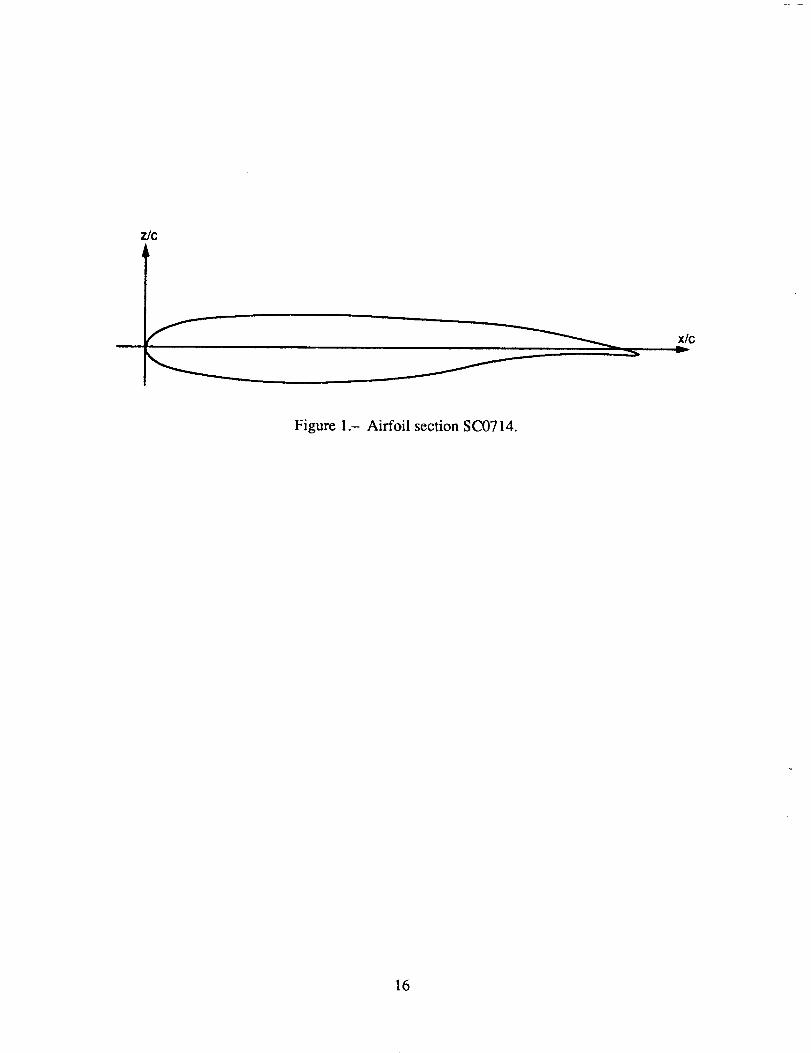
The oblique-wing aircraft under consideration uses an SC(2)-0714 supercritical airfoil section at
all spanwise stations. The thickness-to-chord ratio is maintained at 14% throughout the span. The profile
of this airfoil section is shown in figure 1. Knowing the values of the z coordinates as a function of x,
it is a simple matter to calculate the required values of dz/dx and dt/dx.
However, when the wing is skewed, the problem becomes more complex. Because the WING3D
program requires that two sides of each aerodynamic panel run parallel to the free-stream direction, the
thickness and slope information must be computed for the section of the wing parallel to the free stream.
This section profile is different from the original SC(2)-0714 airfoil when the wing is skewed, and the
aerodynamic models must take that difference into account.
Currently, only one skewed position (45 ° ) is considered; thus, the new section properties are
computed by means of interactive computer graphics capability. If several arbitrary skew angles must be
considered, it may be preferable to develop an algorithm to compute z(x,y). In this study, the wing was
modeled using a Hewlett-Packard HPSX workstation running the I-DEAS object-modeling software.
First, the unskewed wing-surface model was created and the model was rotated through 45 ° (right wing
forward). The skewed model was sliced at the desired spanwise stations. This gave values for z(x)45,
and it was straightforward to process the section data to obtain the required thickness and slope informa-
tion. In general, there are five distinct regions for these values, which are shown in figure 2. Over the
central and midspan regions, dz/dx and dt/dx are almost constant. In the two areas near the tips, the sec-
tion profiles are extremely distorted compared to the airfoil at the central section.
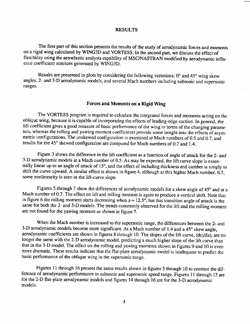
RESULTS
The fh'st part of this section presents the results of the study of aerodynamic forces and moments
on a rigid wing calculated by WING3D and VORTESS. In the second part, we discuss the effect of
flexibility using the aeroelastic analysis capability of MSC/NASTRAN modified by aerodynamic influ-
ence coefficient matrices generated by WlNG3D.
Results are presented in plots by considering the following variations: 0 ° and 45 ° wing skew
angles, 2- and 3-D aerodynamic models, and several Mach numbers including subsonic and supersonicranges.
Forces and Moments on a Rigid Wing
The VORTESS program is required to calculate the integrated forces and moments acting on the
oblique wing, because it is capable of incorporating the effects of leading-edge suction. In general, the
lift coefficient gives a good measure of basic performance of the wing in terms of the changing parame-
ters, whereas the rolling and yawing moment coefficients provide some insight into the effects of asym-
metric configurations. The unskewed configuration is examined at Mach numbers of 0.5 and 0.7, and
results for the 45 ° skewed configuration are computed for Mach numbers of 0.7 and 1.4.
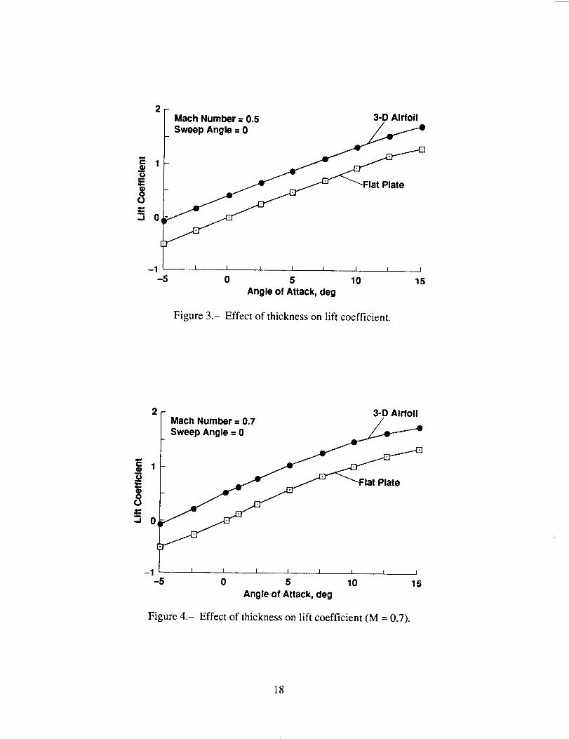
Figure 3 shows the difference in the lift coefficient as a function of angle of attack for the 2- and
3-D aerodynamic models at a Mach number of 0.5. As may be expected, the lift curve slope is essen-
tially linear up to an angle of attack of 15 ° , and the effect of including thickness and camber is simply to
shift the curve upward. A similar effect is shown in figure 4, although at this higher Mach number, 0.7,
some nonlinearity is seen in the lift-curve slope.
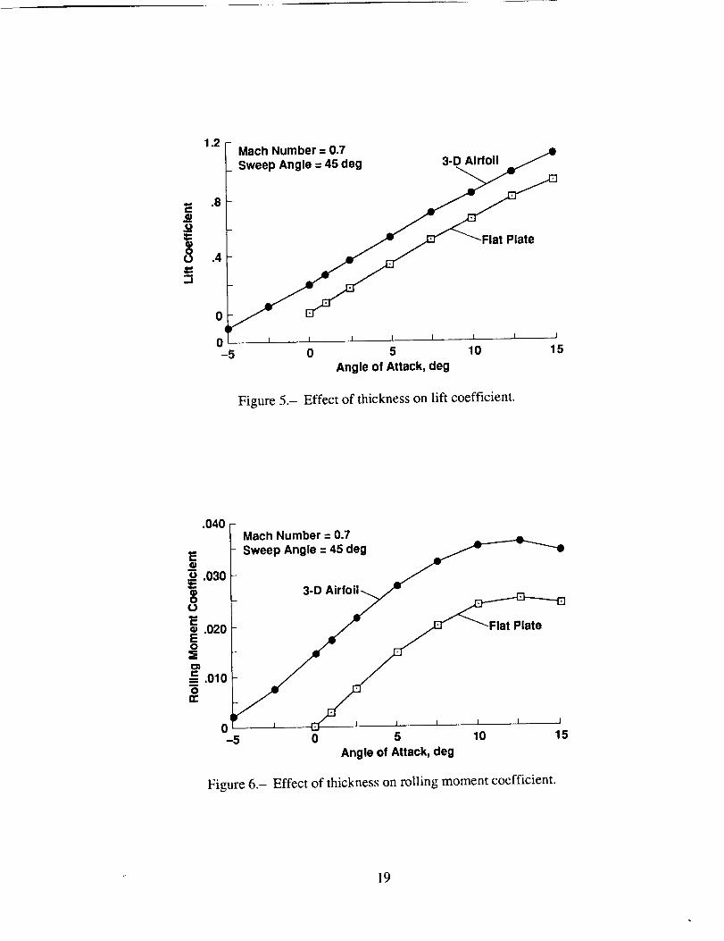
Figures 5 through 7 show the differences of aerodynamic models for a skew angle of 45 ° and at a
Mach number of 0.7. The effect on lift and rolling moment is again to produce a vertical shift. Note that
in figure 6 the rolling moment starts decreasing when a -- 12.5 °, but this transition angle of attack is the
same for both the 2- and 3-D models. The trends commonly observed for the lift and the rolling moment
are not found for the yawing moment as shown in figure 7.
When the Mach number is increased to the supersonic range, the differences between the 2- and
3-D aerodynamic models become more significant. At a Mach number of 1.4 and a 45 ° skew angle,
aerodynamic coefficients are shown in figures 8 through 10. The slopes of the lift curve, (dcl/da), are no
longer the same with the 2-D aerodynamic model, predicting a much higher slope of the lift curve than
that in the 3-D model. The effect on the rolling and yawing moments shown in figures 9 and 10 is even
more dramatic. These results indicate that the fiat-plate aerodynamic model is inadequate to predict the
basic performance of the oblique wing in the supersonic range.
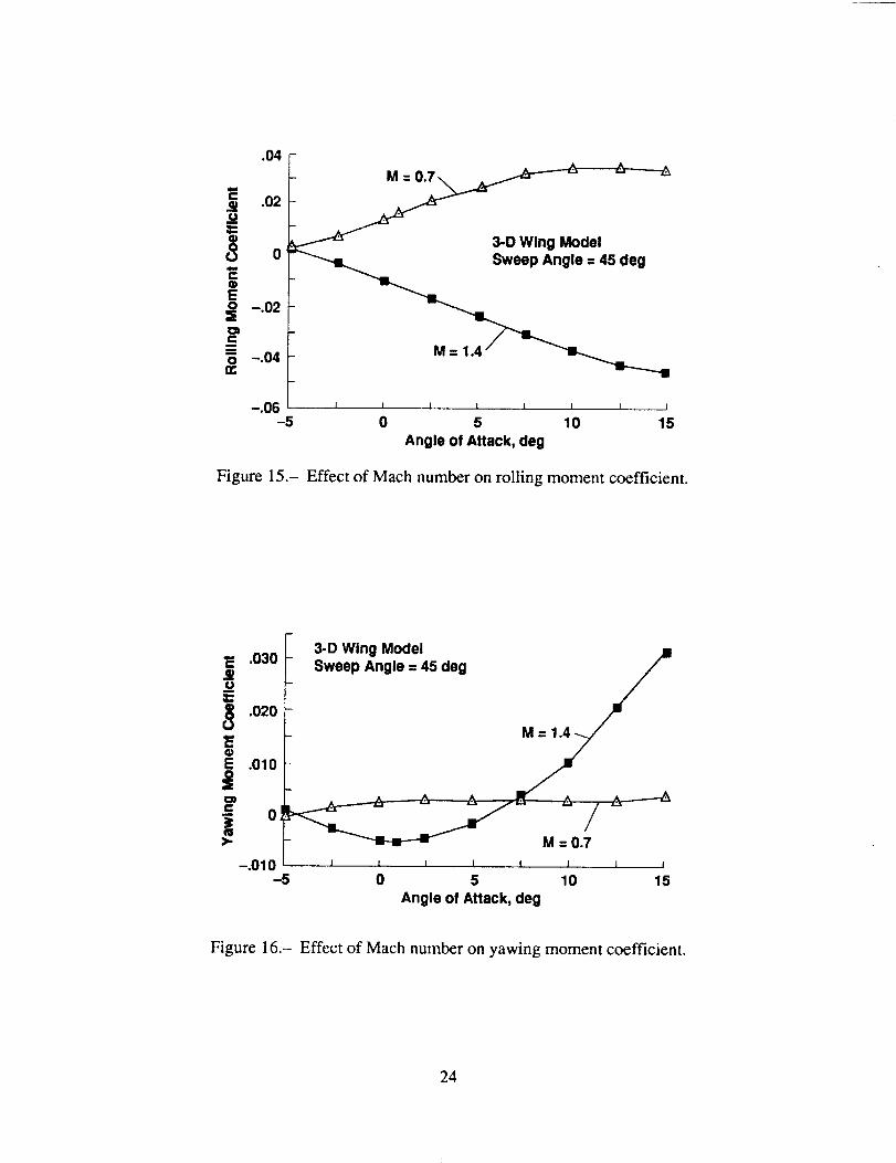
Figures 11 through 16 present the same results shown in figures 5 through 10 to contrast the dif-
ference of aerodynamic performance in subsonic and supersonic speed range. Figures ! 1 through 13 are
for the 2-D fiat-plate aerodynamic models and figures 14 through 16 are for the 3-D aerodynamicmodels.
4

As indicatedin figure 2, therearefive distinctregionsfor thethicknesspropertiesof the45°wing. Overthecentralpartsof thewing, thedataproducedbytheinteractivegraphicsmethodis consis-tentoverall thesections,butat thewing tipsthereductionin thechordmadeit moredifficult to obtainaccuratesectionprofile data.To checkif theaccuracyof thetip-thicknessdatasignificantlyaffect thecomputedaerodynamicperformances,theVORTESSprogramwasrunwith amodified tip-thicknessdistribution.Themodificationwasto usethesectiondataat theboundaryof thetip andthemainwingthroughoutthetip regionfor eachof theright andleft tips.Insignificantdifferencesarefound in the liftcoefficientsasshownin figure 17.Theyawingmomentcharacteristicsat aMachnumberof 1.4arestronglyaffectedbythetip modelsasshownin figure 18;however,theirmagnitudeswereextremelysmall.
Forces and Moments on Flexible Wing
In the following, the results of aeroelastic analyses obtained by substituting the aerodynamic
influence coefficient matrices generated by WING3D into the MSC/NASTRAN finite element program
are presented. The procedure used in the present study is outlined in the Appendix, and the required
DMAP statements are also included for reference purposes. Note that the DMAP statements included
here are applicable only to version 64 of MSC/NASTRAN.
The aerodynamic influence coefficient matrix required for the MSC/NASTRAN static aeroelastic
analysis consists of the effect on the normal component of velocity on a particular panel because of the
existence of all the other panels. For the 2-D fiat-plate model, there is a normal component correspond-
ing to ACp and for the 3-D model, there is an additional normal component resulting from thickness
variations. After running WING3D, some processing of the data is required to arrive at a form that is
compatible with the MSC/NASTRAN input requirements.
Computation of the aerodynamic coefficients of a flexible wing may be carried out either by pro-
cessing the reaction forces at the pivot or by processing the deformed shape by the WING3D program.
Unfortunately, prior to launching the calculation of the aerodynamic coefficients of a flexible wing, the
Oblique Wing Research Aircraft Program was cancelled for reasons beyond the control of the authors.
Consequently, the results summarized in this report are limited to those obtained at the beginning of the
analysis of the flexible wing.
An aeroelastic analysis is performed for the 45 ° skewed wing at a Mach number of 0.7 for both
the 2-D fiat-panel model and the 3-D wing model. The results are summarized in the form of pressure
coefficients at the centers of the aerodynamic panels, and nodal displacements.
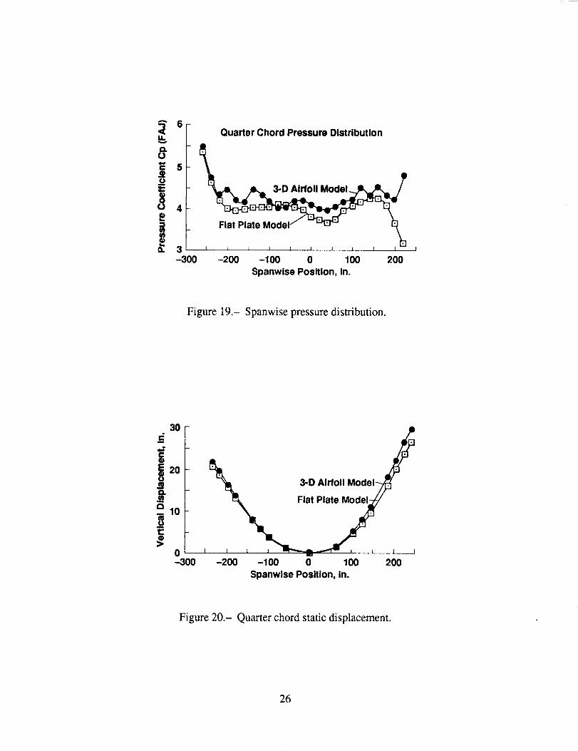
Figure 19 shows the spanwise quarter-chord pressure distribution at several spanwise locations
for both the 2- and 3-D aerodynamic models. The main difference between the two occurs near the tips,
particularly in the forward swept tip. It is also observed that the spanwise pressure distribution obtained
by the 3-D model is not smooth, and this is perhaps an indication that the mesh sizes may require further
refinements. It is clear that the 3-D model predicts slightly higher lift coefficients than the 2-D model
does, resulting in slightly larger aeroelastic deformation as shown in figure 20. Figure 20 shows the
leading-edge displacement for both the 2- and 3-D models. For the 2-D model the maximum vertical
displacement is 26.53 in. at the leading edge of the forward wing-tip (node 551), and for the 3-D model,

themaximumdisplacementis 29.62in. at thesamenode.Thedifferencein displacementisprimarilyattributedto theextra lift dueto thethicknessandcamber.
RECOMMENDATIONS FOR FUTURE STUDY
First, it is highly recommended that the aerodynamic coefficients for the flexible wing be calcu-
lated. The performance of the flexible wing is significantly different from that of the rigid wings. The
design of the oblique-wing structures must take the aeroelastic effects into account, and possibly, even
take advantage of them.
As described in the Appendix, aeroelastic analyses of oblique-wing configurations require a sig-
nificant amount of manual labor. It is recommended that the operation of the programs be streamlined by
integrating all the programs on one computer, possibly on a high-performance workstation. If the propri-
etary program MSC/NASTRAN is not available on a particular computer, alternative aeroelastic analy-
sis shells should be considered. The aerodynamic programs WING3D and VORTESS reside on a
VAX/780 and their processing speed is unacceptable for practical applications. Also, a number of minor
discrepancies between these two programs should be resolved. Currently, VORTESS provides more
accurate integrated coefficients than WlNG3D, but it is not set up to output the aerodynamic influence
coefficient matrices. Since VORTESS is capable of including the corrections needed to account for the
leading-edge suction, it should be modified to produce the relevant aerodynamic influence coefficientmatrices.
The aerodynamic programs used in this study require that two sides of the quadrilateral panels be
parallel to the free-stream line direction. This means we have to create a new aerodynamic panel
arrangement for each of the different skew angles to be analyzed. It is not acceptable to use the manual
process with the interactive computer graphics software to generate the aerodynamic panel data for the
skewed configuration, because the resolution is not satisfactory and the process requires extraordinary
amounts of time. It is necessary to develop a new automated method for calculating the wing geometry.
The problem of changing the geometric model for every change in skew angle would be avoided if the
aerodynamic code did not require that two of the edges of the panel are parallel to the free stream. An
example of such a code is PANAIR. However, capability of such programs must be evaluated with par-
ticular emphasis on the flexibility of generating the aerodynamic influence coefficient matrices in a
compatible form with the aeroelastic analysis code and also on possible modifications to predict the
leading-edge suction forces.
Finally, aeroelastic tailoring of the composite wing should be undertaken with aeroelastic analy-
sis and sensitivity analysis capability. It is expected that the performance of the oblique wing is sensitive
to the aeroelastic responses and by taking advantage of the design flexibility provided by the applica-
tions of modern composite materials, we may be able to exploit the potential of this new concept.
Structural optimization technology is readily incorporated once the sensitivity analysis capabilitybecomes available.
6

CONCLUSIONS
Based on the results reported in this study and the results given in reference 1, we can conclude
that the use of the three-dimensional aerodynamic model is essential to the analysis and design of the
oblique wing. Even though most of the aeroelastic analysis capabilities are developed to analyze sym-
metric aircraft, they can be applicable to the oblique wing configurations by generating the aerodynamic
matrices externally, considering the specific features of the asymmetric configurations of the oblique
wing.
APPENDIX
The sequence in which a set of programs is activated to perform aerodynamic and aeroelastic
analyses is shown in figure A. 1. The ovals represent data files (both input and output), the rectangles
represent VAX FORTRAN programs, and the double rectangles represent the Job Control Language
(JCL) file together with the relevant data to run the jobs on the Cray-XMP/48 at NASA Ames ResearchCenter.
GEOMWBODY generates the aerodynamic panel data for the specified plan-form, and can also
generate the 3-D data for a limited set of airfoil sections. If the airfoil is not one of the preselected air-
foils included in the GEOMWBODY internal library, then dz,/dx data are required to generate the thick-
ness information for an airfoil section. This is the case for the oblique wing analyzed in this study, which
has a unique supercritical airfoil section, and, when skewed, these sections are also distorted. In order to
execute either VORTESS or WING3D, the output from GEOMWBODY and dz/dx must be combined
by the GEO program.
At this point, VORTESS may be executed if integrated aerodynamic coefficients are desired, but
in order to compute the aerodynamic influence coefficient matrices, WING3D must be activated. The
output from WING3D is then converted to a binary form by TESTINPUT on the same computer that
processes MSC/NASTRAN, so that it is compatible with the MSC/NASTRAN input requirements. This
binary file is catalogued on CRAY-XMP/48 as CRAY.PDN. When the static aeroelasticity analysis job
is prepared as CRAY.DAT and submitted to CRAY for execution, the file CRAY.RUN is recognized as
a file that contains the aerodynamic influence coefficient matrices.
Figure A.2 is a listing of a sample terminal session to run the interactive GEOMWBODY pro-
gram. Terminal sessions for VORTESS and WING3D are shown in figures A.3 and A.4, respectively.
Finally, figure A.5 lists the Cray JCL to run MSC/NASTRAN with the AIC matrices replaced by the
output of WING3D. This JCL contains the DMAP alter statements which are required to substitute theAIC matrices.

GEOMWBODY
FILE1.GEO
DZ/DXDT/DX
FILE2.GEO
FILE.GEO
GEO 1
WING3D
MAKEMX
TESTINPUT II
CRAY.DAT I!
WlNG3D.PRT
TEST.DAT
CRAY.PDN
CRAY.OUT
Figure A. 1.- Analysis process flow diagram.

$ run geomwbody
NASA-AMES WING-BODY GEOMETRY PROGRAM
ENTER NAME OF OUTPUT FILE: test.geo
IS OUTPUT FILE TO BE FORMATTED FOR
I PANAIR
2 WINGBODY
2
SELECT FUNCTION TO BE PERFORMED
-I
0
I
2
3
4
3
DEFINE WING ROOT CHORD:
LEADING EDGE, X= 660.46
TRAILING EDGE, X= 688.59
Y= -235.17
Z= 0
DEFINE WING TIP CHORD:
LEADING EDGE, X= 628.4
TRR#LING EDGE, X= 685.7!
Y= -203.11
Z= 0
ENTER NO. OF ROWS OF PANELS: 10
ENTER NO. OF COLUMNS OF PANELS: 2
EXIT
END DEFINITION OF THIS VEHICLE
DEFINE A BODY SEGMENT
DEFINE A DISK (PANAIR ONLY)
DEFINE A WING REGION
ADD AN END-TIP TO A PREVIOUSLY DEFINED WING
THE ROOT, TIP, AND SPAN ARE SUBDIVIDED ACCORDING TO VARIOUS
SPACING RULES
THE ACCEPTABLE RULES ARE:
0 SPECIFIED SPACING
I UNIFORM SPACING
2 FULL COSINE SPACING (DENSE NEAR BOTH ENDPOINTS)
3 HALF COSINE SPACING (DENSE NEAR FIRST POINT)
4 HALF SINE SPACING (DENSE NEAR LAST POINT)
ENTER SPACING RULE FOR ROOT CHORD: I
ENTER SPACING RULE FOR TIP CHORD: I
ENTER SPACING RULE FOR SPAN: I
ACCEPTABLE CHOICES FOR AIRFOIL SECTION ARE:
Figure A.2.- Interactive processing of the geometry definition program.
9

0 ZERO THICKNESS
I PARABOLIC ARC
2 DOUBLE WEDGE
3 30-70 HEX
4 WEDGE (THICK BASE)
5 NACA O00X
6 NACA 6400X
7 NACA 6500X
8 RAE 101
SELECT AIRFOIL SECTION FOR THIS WING: 0
NASA/AMES WING BODY GEOMETRY PROGRAM
WING GRID DEFINITION POINTS
X-ROOT
660 46002
Y-SPAN Z-SPAN
-235.17000 0,00000
-219,14000 0.00000
-203,11000 0,00000
663
666
668
671
674
677
680
682
685
688
27301
08600
89899
71198
52496
33759
15094
96393
77692
59003
X-TIP
628 40002
634 13104
639 86206
645 59308
651 32410
657 05511
662 78613
668 51715
674 24817
679 97919
685 71002
SELECT FUNCTION TO BE PERFORMED
-I EXIT
0 END DEFINITION OF THIS VEHICLE
I DEFINE A BODY SEGMENT
2 DEFINE A DISK (PANAIR ONLY)
3 DEFINE A WING REGION
4 ADD AN END-TIP TO A PREVIOUSLY DEFINED WING
-I
FORTRAN STOP
$
Figure A.2.- Concluded.
10

$ run vortess
Three-Dimensional Wing Program
Enter name of geometry file:r45tu,geo
Reading geometry file...
300 panels read from input file.
Enter the output level code:
=0 no output
=I integrated forces and moments
=2 local pressures
=3 panel corner points
=4 local velocity components
=8 panel areas and centroids
=9 aerodynamic matrices
I
Enter the free-stream Mach number: 0.7
Specify the symmetry of the configuration.
0 No symmetry
I Right/Left symmetry
Enter Symmetry code: 0
Enter SREF: 42241.8
Enter CBAR: 87,78
Enter SPAN: 481.22
Enter reference axis position XREF: 425,29
Enter reference axis position YREF: 0.0
Enter reference axis position ZREF: 54.32
Computing aerodynamic matrices...
Enter (I) to design for a given Cp
(2) to analyze a given design
2
Performing L-U decomposition...
Condition number= 1.4462E+01
Enter angle of attack (or ^Z to quit) : 5,0
Formula for pressures (3-2nd order, 4-isen): 4
Computing aerodynamic matrices,..
Enter (I) to design for a given Cp
(2) to analyze a given design
2
Performing L-U decomposition...
Condition number= 1.4462E+01
Enter angle of attack (or ^Z to quit) : ^Z
Files VORTESS.CPS, VORTESS.POU, and VORTESS.FNM created.
Normal termination of VORTESS.
$
Figure A.3.- Interactive processing of VORTESS program.
11
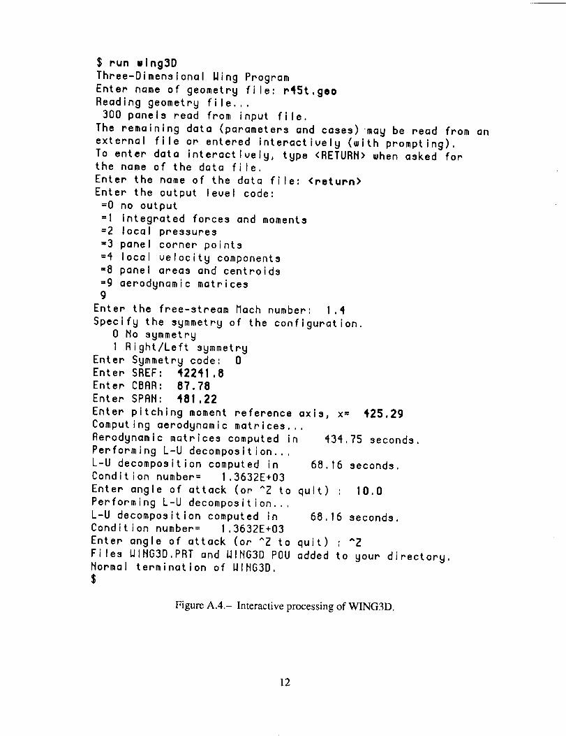
$ run wlng3D
Three-Dimensional Wing Program
Enter name of geometry file: r45t.geo
Reading geometry file...
300 panels read from input file.
The remaining data (parameters and cases)may be read from an
external file or entered interactively (with prompting).
To enter data interactively, type <RETURN> when asked for
the name of the data file.
Enter the name of the data file: <return>
Enter the output level code:
=0 no output
=I integrated forces and moments
=2 local pressures
=3 panel corner points
=4 local velocity components
=8 panel areas and centroids
=9 aerodynamic matrices
9
Enter the free-stream Mach number: 1.4
Specify the symmetry of the configuration.
0 No symmetry
I Right/Left symmetry
Enter Symmetry code: 0
Enter SREF: 42241,8
Enter CBAR: 87.78
Enter SPAN: 481.22
Enter pitching moment reference axis, x= 425,29
Computing aerodynamic matrices...
Aerodynamic matrices computed in 434.75 seconds.
Performing L-U decomposition...
L-U decomposition computed in 68.16 seconds.
Condition number= 1,3632E+03
Enter angle of attack (or ^Z to quit) : 10.0
Performing L-U decomposition...
L-U decomposition computed in 68.16 seconds.
Condition number = 1.3632E+03
Enter angle of attack (or ^Z to quit) : ^Z
Files WING3D.PRT and WING3D POU added to your directory.
Normal termination of WING3D.
$
Figure A.4.- Interactive processing of WING3D.
12

JOB,JN=OBLIQUE,T=600.
ACCOUNT,AC=xxxxxxx,US=xxxxxx,UPW=xxxx.
ACCESS,DN=NASTRUN,PDN=NASTRAN, ID=EEEMKC,OWN=EEMMKC.
ACCESS,DN=FT11,PDN=R45TA, ID=PANEL.
CALL,DN=NASTRUN,CNS.
NASTRAN,GREEN,NELSON.
IEOF
*IDENT GET
/EOF
*DECK X
NASTRAN PREFOPT=2,SYSTEM(7)=IO
ID STATIC AERO TEST
SOL 21, 0
DIAG 8,13
TIME 50.
ALTER 2
FILE UX=SAVE $
ALTER 751,751 $ ERROR IN DMAP
ALTER 966,966
ALTER 881,881
INPUT4 IXAJJ,,,,I11111-1 $
ADD XAJJ,/AJJ/(-I.,O.) $
ALTER 971,971
ALTER 880
$$ ELIMINATE MOMENT TERMS FROM SKJ FOR WOODWARD
$ AERONAUTICS
$PARAML SKJIITRAILERI21V,N,NWOOO $
MATGEN ,IPWOODI4111NWOODIOIII212 $
PAATN SKJ,,PWOODISKJI,,,II $
MERGE SKJI,,,,,PWOOD/SKJWII $
EQUIV SKJW,SKJIALWAYS $
ALTER 968
PARAML PSALIITRAILERI51V,N,NPSAL $
PARAM IISUBINPSALINPSALII $
COND UNTRM3,NPSAL $
ALTER 970
LABEL UNTRM3 $
CEND
TITLE = STATIC AERO TEST
SUBTITLE = 300 SQ, FT. OBLIQUE WING
LABEL = 3-D AERODYNAMIC MODEL, 45 DEG.
Figure A.5.- MSC/NASTRAN aeroelastic analysis deck setup on CRAY XMP/48.
13
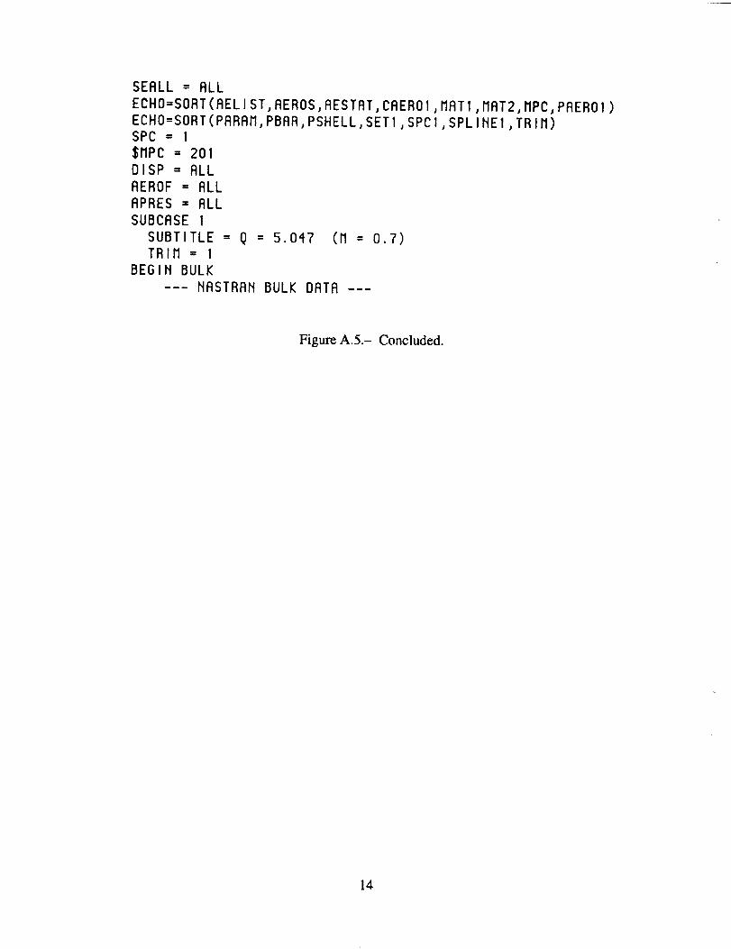
SEALL = RLL
ECHO=SORT(RELIST,AEROS,AESTAT,CAERO1,MAT1,MRT2,MPC,PAEROI)ECHO=SORT(PARAM,PBRR,PSHELL,SET1,SPCI,SPLINE1,TRIM)SPC = 1
$MPC = 201
DISP = RLL
AEROF = RLL
RPRES = RLL
SUBCRSE 1
SUBTITLE = Q = 5.047 (M = 0,7)
TRIM = I
BEGIN BULK
--- NASTRAN BULK DATA ---
Figure A.5.- Concluded.
14

REFERENCES
Lee, I.; Miura, H.; and Chargin, M. K.: Static Aeroelastic Analysis for Generic Configuration Aircraft.
NASA TM-89423, 1987.
Rodden, W. P.; Harder, R. L.; and Bellinger, E. D.: Aeroelastic Addition to NASTRAN.
NASA CR-3094, 1979.
Woodward, F. A." An Improved Method for the Aerodynamic Analysis of Wing-Body-Tail Configura-
tions in Subsonic and Supersonic Flow. NASA CR-2228, 1973.
15
7./C
X/Cv
Figure 1.- Airfoil section SC0714.
16

f
6O
2
_-o
-1-5
I
I I I I I I i I
0 5 10 15
Angle of Attack, deg
Figure 3.- Effect of thickness on lift coefficient.
2
41
-1-5
t 3-D AirfoilMach Number = 0.7 /
Sweep Angle = 0
I _ I J I I I I
0 5 10 15
Angle of Attack, deg
Figure 4.- Effect of thickness on lift coefficient (M = 0.7).
18
1.2
.8
0
0-5
Mach Number = 0.7
Sweep Angle = 45 deg
, L, , I 1 l I 1 . L ,. I
0 5 tO t5
Angle of Attack, deg
Figure 5.- Effect of thickness on lift coefficient.
.040 -
.030o
.020
_¢°_.010
0-5
Mach Number = 0.7
Sweep Angle = 45 deg
_ 3-D Airfoil_._ .,,,=
I 1_ I I L, I I I
0 5 10 15
Angle of Attack, deg
Figure 6.- Effect of thickness on rolling moment coefficient.
19

.030
.020
.010
0 _
-.010-5
/,Mach Number = 0.7 /_
- SweepAngle=45deg /f" "'
- 3-0 Ai_j/
_Flat Plate
I 1 I t I I I I
0 5 10 15Angle of Attack, deg
Figure 7.- Effect of thickness on yawing moment coefficient.
.7
.5
!
_=,.1
-.1-5
_ sMa:hepN_nmgb:r=45"4 eg
- Flat Plat__
_3-D Airfoil
i I I I I I 1 I
0 5 10 15Angle of Attack, deg
Figure 8.- Effect of thickness on lift coefficient.
2O

.02
"6
, -.02
.==_c -.04
-.06
.... -D Airfoil
Mach Number = 1.4 - -'_Sweep Angle = 45 deg
I I,. 1 I I I i J
-5 0 5 10 15
Angle of Attack, deg
Figure 9,- Effect of thickness on rolling moment coefficient.
.004
_oca¢::
.002
E 0 q0
"_ -.002>.
-.004-5
Mach Number = 1.4
- Sweep Angle = 45 deg
I . t .... I 1 I 1 I t
0 5 10 15
Angle of Attack, deg
Figure 10.- Effect of thickness on yawing moment coefficient.
21

1.0
.8
"7.2
00
2-D Wing Model A
Sweep Angle = 45 deg
M=1.4
I
4 8 12 16
Angle of Attack, deg
Figure 11.- Effect of Mach number on lift coefficient (2-D model).
.O3
.02
Eo.01
t"°u
2.D Wing
_ Sweep Angle = 4_
I I 1 I I I I I
0 4 8 12 16Angle of Attack, deg
Figure 12.- Effect of Mach number on rolling moment coefficient.
22

.030"_ .025
.020
i .015.010
.005
| o,>" -.005 J
0 16
2-D Wing
Sweep Angle = 45 deg /
I I i I --I I I I
2 4 6 8 10 12 14
Angle of Attack, deg
Figure 13.- Effect of Mach number on yawing moment coefficient.
1.2
.8
0
-5
_wDepnAgngl°d=e/5 de g _/--_
I I I t I I I I
0 5 10 15
Angle of Attack, deg
Figure 14.- Effect of Mach number on lift coefficient.
23
.O4
.02
0
-.02
-- -.04
__l_ngle = 45 deg
M=1.4
-.06 l l J _ i _ J j-5 0 5 10 15
Angle of Attack, deg
Figure 15.- Effect of Mach number on rolling moment coefficient.
.030o
.020
.010
0
-.010-5
3-D Wing Model _jj
Sweep Angle = 45 deg /
- _ M=0.7
I I I I I 1 I I
0 5 10 15
Angle of Attack, deg
Figure 16.- Effect of Mach number on yawing moment coefficient.
24

.J
.5
.3
.1
-.1
Mach Number = 1.4_ Sweep Angle = 45 deg
Modified Tip Model_ _:_:_
Orlginal Tip Model
, I . .L .1 I i I I .I
-5 0 5 10 15
Angle of Attack, deg
Figure 17.- Effect of tip model on lift coefficient.
Em .0040
_ .0030 I
_ .0020
.0010>-
0-5
L I J l I I 1 i
0 5 10 15
Angle of Attack, deg
Figure 18.- Effect of tip models on yawing moment coefficient.
25
A
6tlv
5
L--
_. 3-300
Quarter Chord Pressure Distribution
_Flat Plate Model f _ t_
I i I I I ! I I I I
-200 -100 0 100 200
Spanwlse Position, in.
Figure 19.- Spanwise pressure distribution.
'20 _ 3-D Airfoil Mod
_" lat
-300 -200 -100 0 100 200Spanwlse Position, In.
Figure 20.- Quarter chord static displacement.
26
_/_A Report Documentation PageNaional Aet onau_,cs and
Space AdministxaUon
1. Report No. 2. Government Accession No. 3. Recipienrs Catalog No,
NASA TM- 102231
4. Title and Subtitle
Static Aeroelastic Analysis of a Three-Dimensional
Generic Wing
7. Author(s)
John A. Green, In Lee, and Hirokazu Miura
9. Performing Organization Name and Address
Ames Research Center
Moffett Field, CA 94035-1000
12. Sponsoring Agency Name and Address
National Aeronautics and Space Administration
Washington, DC 20546-0001
5, Report Date
February 1990
6. Performing Organization Code
8. Performing Organization Report No.
A-89239
10. Work Unit No.
533-06-01
11. Contract or Grant No.
13. Type of Report and Period Covered
Technical Memorandum
14. Sponsoring Agency Code
15. Supplementary Notes
Point of Contact: Hirokazu Miura, Ames Research Center, MS 237-11, Moffett Field, CA 94035-1000
(415) 604-5888 or FFS 464-5888
16. Abstract
This report represents a continuation of research on the static aeroelastic analysis of a generic wing
configuration. Results of the study of the asymmetric oblique-wing model developed by Rockwell
International, in conjunction with the NASA Oblique Wing Research Aircraft Program, are reported.
The capability to perform static aeroelastic analyses of an oblique wing at arbitrary skew positions is
demonstrated by applying the MSC/NASTRAN static analysis scheme modified by the aerodynamic
influence coefficient matrix created by the NASA Ames aerodynamic panel codes. The oblique wing is
studied at two skew angles, and in particular, the capability to calculate three-dimensional thickness
effects on the aerodynamic properties of the wing is investigated. The ability to model asymmetric
wings in both subsonic and supersoinic Mach numbers is shown. The aerodynamic influence coeffi-
cient matrix computed by the external programs is inserted in MSC/NASTRAN static aeroelasticity
analysis run stream to compute the aeroelastic deformation and internal forces. Various aerodynamic
coefficients of the oblique wing were computed for two Mach numbers, 0.7 and 1.4, and the angle of
attack -5 ° through 15 °,
17. Key Words (Suggested by Author(s))
Aeroelasticity
Oblique wing
NASTRAN
Flexible wing
18. Distribution Statement
Unclassified-Unlimited
Subject Category-07
19. Security Classif. (of this report)
Unclassified20. Security Classif. (of this page)
Unclassified21 No. of Pages
29
22. Price
A03
HASA FORM 1626 OCT86
For sale by the National Technical Information Service, Springfield, Virginia 22161


