static and dynamic analysis of r.c building … · · 2017-07-08of masonry infill wall in...
TRANSCRIPT
International Research Journal of Engineering and Technology (IRJET) e-ISSN: 2395-0056
Volume: 04 Issue: 07 | July -2017 www.irjet.net p-ISSN: 2395-0072
© 2017, IRJET | Impact Factor value: 5.181 | ISO 9001:2008 Certified Journal | Page 383
STATIC AND DYNAMIC ANALYSIS OF R.C BUILDING FRAME WITH INFILL
Nasratullah Zahir1, Dr. Vivek Garg2
1 M. Tech. Research Scholar, Department of Civil Engineering, Maulana Azad National Institute Technology, Bhopal,
India. 2 Assistant Professor, Department of Civil Engineering, Maulana Azad National Institute Technology, Bhopal, India. ---------------------------------------------------------------------***---------------------------------------------------------------------
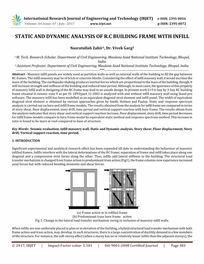
Abstract - Masonry infill panels are widely used as partition walls as well as external walls of the building to fill the gap between RC frames. The infill masonry may be of brick or concrete blocks. Considering the effect of infill masonry wall, it would increase the mass of the building. The earthquake shaking produces inertial forces which are proportional to the mass of the building, though, it will increase strength and stiffness of the building and reduced time period. Although, in most cases, the ignorance of this property of masonry infill wall in designing of the RC frame may lead to an unsafe design. In present work G+9 6-bay by 3-bay RC building frame situated in seismic zone V as per IS: 1893(part 1)-2002 is analyzed with and without infill masonry wall using Staad pro software. The masonry infill has been modelled as an equivalent diagonal strut element and infill panel. The width of equivalent diagonal strut element is obtained by various approaches given by Smith, Holmes and Paulay. Static and response spectrum analysis is carried out on bare and infill frame models. The results obtained from the analysis for infill frame are compared in terms of story shear, floor displacement, story drift, time period and vertical support reaction with bare frame. The results obtain from the analysis indicates that story shear and vertical support reaction increase, floor displacement, story drift, time period decreases for infill frame models compare to bare frame model by equivalent static method and response spectrum method. This increase in ratio is found to be more at roof compared to base of structure. Key Words: Seismic evaluation, infill masonry wall, Static and Dynamic analysis, Story shear, Floor displacement, Story drift, Vertical support reaction, time period. 1. INTRODUCTION Significant experimental and analytical research effort has been expended till date in understanding the behaviour of masonry infilled frames. Infills interfere with the lateral deformations of the RC frame; separation of frame and infill takes place along one diagonal and a compression strut forms along the other. Thus, infills add lateral stiffness to the building. The structural load transfer mechanism is changed from frame action to predominant truss action (Fig1), the frame columns now experience increased axial forces but with reduced bending moments and shear forces.
(a) Frame action in in infilled frame
(b) Predominant truss bare frame action Fig 1: Change in the lateral load transfer mechanism owing to inclusion of masonry infill walls.
When infills are non-uniformly placed in plan or in elevation of the building, a hybrid structural load transfer mechanism with both frame action and truss action, may develop. In such structures, there is a large concentration of ductility demand in a few members of the structure. For instance, the soft-storey effect (when a storey has no or relatively lesser infills than the adjacent storeys), the

International Research Journal of Engineering and Technology (IRJET) e-ISSN: 2395-0056
Volume: 04 Issue: 07 | July -2017 www.irjet.net p-ISSN: 2395-0072
© 2017, IRJET | Impact Factor value: 5.181 | ISO 9001:2008 Certified Journal | Page 384
short-column effect (when infills are raised only up to a partial height of the columns), and plan-torsion effect (when infills are unsymmetrically located in plan), cause excessive ductility demands on frame columns and significantly alter the collapse mechanism. Another serious concern with such buildings is the out-of-plane collapse of the infills which can be life threatening. Even when the infills are structurally separated from the RC frame, the separation may not be adequate to prevent the frame from coming in contact with the infills after some lateral displacement; the compression struts may be formed and the stiffness of the building may increase. Infills possess large lateral stiffness and hence draw a significant share of the lateral force. When infills are strong, strength contributed by the infills may be comparable to the strength of the bare frame itself. The mode of failure of an infilled building depends on the relative strengths of frame and infill (Table 1). And, its ductility depends on the (a) infill properties, (b) relative strengths of frame and infill, (c) ductile detailing of the frame when plastic hinging in the frame controls the failure, (d) reinforcement in the infill when cracking in infills controls the failure, and (e) distribution of infills in plan and elevation of the building.
Table 1: Modes of failure of masonry infilled RC frames
Frames Weak infill Strong infill Weak frame - Diagonal cracks in infill
Plastic hinges in columns Frame with weak Joints and Strong members
Corner crushing of infills Cracks in beam-column joints
Diagonal cracks in infill Cracks in beam-column joints
Strong frame Horizontal sliding in infills - In a bare frame, inelastic effects in RC frame members and joints cause energy dissipation, while in an infilled frame, inelastic effects in infills also contribute to it. Thus, energy dissipation in an infilled frame is higher than that in the bare frame. If both frame and infill are detailed to be ductile, then stiffness degradation and strength deterioration under cyclic loading are nominal. However, if inelastic effects are brittle in nature (e.g., cracking of infill, bond slip failure in frame, or shear failure in frame members), the drop in strength and stiffness under repeated loading may be large. When physical gaps exist between the frame and the infills, or when sliding takes place in infills along mortar beds, the hysteresis loops demonstrate increased pinching 2. LITERATURE REVIEW Merabi (1994) et al. examined that the brittle shear failure of the column on the windward side while investigating the infilled frame structure which had strong infill panel and weak frame. However, the increase in lateral load resistance was found even after the shear failure in column, indicating some ductility due to infill. On the contrary, the formation of hinges in the columns and slip in the bed joints were observed in a weak infill frame test specimen. The stronger frame with stronger infill had failed by crushing of infill as the shear failure of columns was prevented due to enough shear reinforcement and bigger sized column. A comprehensive experimental and analytical investigation into the behaviour of infilled structures was conducted by him. He reported that the infill has significant improvement on the lateral strength and stiffness of a bare frame and also significantly improves the energy dissipation capability of the structure. The aspect ratio of the infill panel has little influence on the behaviour of the frame while the cyclic loadings degrade the structure faster than the monotonic loadings. He also reported that the increase in vertical loads significantly improves the lateral load carrying capacity of the structure, the distribution of vertical load between beam and column has insignificant influence. He indicated the increase in lateral load carrying capacity by increasing the number of storey, however this may not be true for high rise structures and thus similar study has to be conducted for higher number of stories. Fardis (1996) et al. investigated the seismic response of an infilled frame which had weak frames with strong infill material. It was found that the strong infill which was considered as non-structural is responsible for earthquake resistance of weak reinforced concrete frames. However, since the behaviour of infill is unpredictable, with the likelihood of failing in brittle manner, it was recommended to treat infill as non-structural component by isolating it from frames. On the contrary, since infill is extensively used, it would be cost effective if positive effects of infill is utilised.

International Research Journal of Engineering and Technology (IRJET) e-ISSN: 2395-0056
Volume: 04 Issue: 07 | July -2017 www.irjet.net p-ISSN: 2395-0072
© 2017, IRJET | Impact Factor value: 5.181 | ISO 9001:2008 Certified Journal | Page 385
Scarlet (1997) et al. Studied the qualification of seismic forces in open ground story buildings. A multiplication factor for base shear for open ground story building was suggested. This procedure requires modelling the stiffness of the infill walls in the analysis. The study suggested a multiplication factor from 1.86 to 3.28 as the number of storey increases from six to twenty. Al-Chaar (1998) et al. Performed studies on the behaviour of reinforced concrete frames with masonry infill. The test was conducted on two half scale specimens in which one of the frames was stronger than the other. The stronger frame specimen showed diagonal tension cracking while the weak frame failed because of diagonal cracking as well as hinging of the column at lower end. Both the frames were stated to have shown the same ductile behaviour but the extent of ductility is not specific. Though, he concluded that the infill wall improves the strength, stiffness and energy absorption capacity of the plane structures which are useful for structures in seismic regions. Deodhar and Patel (1998) et al. pointed out that even though the brick masonry in infilled frame are intended to be non-structural, they can have considerable influence on the lateral response of the building. Davis and Menon (2004) concluded that the presence of masonry infill panels modifies the structural force distribution significantly in an open ground storey (OGS) building. The total storey shear force increases as the stiffness of the building increases in the presence of masonry infill at the upper floor of the building. Also, the bending moments in the ground floor columns increase (more than two fold), and the mode of failure is by soft storey mechanism (formation of hinges in ground floor columns). Dominguez (2000) et al. examined the influence of non-structural component on the fundamental period of buildings. The model consists of five storeys, ten storeys and fifteen storeys with equivalent diagonal struts as the infill (non-structural component). It was described that the presence of infill decreases the fundamental period of the structure. When the models was provided with 100mm thick infill, the fundamental period was decreased by 46%, 40% and 34% for five storey, ten storeys and fifteen storeys. When the infill thickness was 200mm, the fundamental period was 53%, 44% and 36% respectively. The trend of decrease in period with increase in thickness is decreasing with the increase in height. Though, the effect of thickness is not significant. The effect strength of infill masonry wall was stated to be insignificant on the fundamental period of the structure as the difference between 2 models which had 8.6MPa and 15.2MPa was 10.4%. The significant difference was observed by increasing the number of bays. When the number of bays was increased to 2, the difference in fundamental period was 15%. Muyeed-Ul-Azami et al. (2005) et al. the structural influence of brick infill masonry wall is generally not considered in the design of columns as well as other structural components of RC building frame. The lateral deflection is reduced considerably in the infilled frame compared to the deflection of the frame without infill. This hints to different steel requirements for frame structures considering infill masonry wall. It is witnessed that frames with infill panel produce much lesser deflections as compared to frames without infill wall. It is also observed that there is no major difference in steel requirements of the interior column but there is a moderate difference in steel requirements in exterior column and significant difference in steel requirements in the corner column. Though, this specifies considering stiffness of the infill may not result in an economy in the design of multi-storied buildings if the number of interior columns is significantly greater compared to the number of exteriors and corner columns. Asokan (2006) et al. studied how the presence of masonry infill walls in the frames of a building changes the lateral stiffness and strength of the structure. This research suggested a plastic hinge model for infill wall to be used in nonlinear performance based analysis of a building and concludes that the ultimate load (UL) approach along with the proposed hinge property provides a better estimate of the inelastic drift of the building. Dorji and Thambiratnam (2009) et al. concluded that the strength of infill in terms of its Young’s Modulus (E) has a significant influence on the global performance of the structure. The stresses in the infill wall decrease with increase in (E) values due to increase in stiffness of the model. The stresses varies with building heights for a given E and seismic hazard. Ruangrassamee et al. (2012) et al. This paper deals with the study of RC building with infill panel under earthquake loading and the influence of infill masonry wall in an earthquake load resisting capacity. It is observed that providing infill masonry walls play the main role in the tsunami load resisting capacity of the RC building. In case, If there is no wall in the building the load resistance of the building is limited to only 138 KN which is governed by the flexural failure of columns. In the middle of the frame, the walls significantly enhance the lateral load capacity of the building to about 700 KN. If the walls are provided in all over the frame, the load resistance capacity is about 700 KN which is limited by shear failure of short columns. In the middle the frame resists the

International Research Journal of Engineering and Technology (IRJET) e-ISSN: 2395-0056
Volume: 04 Issue: 07 | July -2017 www.irjet.net p-ISSN: 2395-0072
© 2017, IRJET | Impact Factor value: 5.181 | ISO 9001:2008 Certified Journal | Page 386
lateral load of the top part load the damage on the masonry infill walls is about 60% and 3 times higher than the resisting load of this building without masonry infill walls. Jamkar et al., (2013) et al. this paper deliberate the behaviour of RC frames with the various arrangement of infill masonry wall when subjected to dynamic earthquake loading. So, the result of the bare frame, frame with infill, soft ground floor and soft basement are compared and the decision is made in view of IS 1893(2002) code. It is summarised that the earthquake-resistant action of RC building frame increases by providing the infill masonry wall beneath plinth compared to the soft basement. In this study Software (ETAB) is used as a tool for analysing the effect of infill on the structural behaviour. It is observed and which provide overestimated values of the fundamental period. 3. METHODOLOGY ADOPTED FOR THE WORK For the present study Equivalent static analysis (ESA) and Response spectrum analysis (RSA) is considered for the comparative study. The building will be analysed for two different cases: i) Considering infill mass but without considering infill stiffness. ii) Considering both infill mass and infill stiffness. 5 models are created for the building considered, bare frame and infill frame by taking various types of modelling approaches given by Smith, Paulay, Holmes and infill panel and are analysed by two methods stated above. The modelling and analysis are done with the aid of software STAAD-PRO V8i in acquiescence with the codes IS: 456-2000 and IS: 1893-2002. The methodology worked out to achieve the above-stated objectives is as follows: 1) Select a building model for the case study. 2) Model the selected building with and without considering infill strength/stiffness. 3) Equivalent static analysis of the selected building models and a comparative study on the results obtained from the analyses to evaluate the effect of considering infill stiffness. 4) Response spectrum analysis of the selected building models and a comparative study on the results obtained from the analyses to evaluate the effect of considering infill stiffness. To assess the effect of varying approaches of modelling the infill wall on the analysis results the various procedures given by Smith, Paulay, Holmes and infill panel are considered and compared with bare frame model. The following results are compared between bare and infilled frame models to evaluate the effect of infill by Equivalent static method and Response spectrum method. 1) To compare Story shear, Floor displacement, Story drift, Time period and Support reaction between bare and infill frame model by Equivalent static method. 2) To compare Story shear, Time period and support reaction between bare and infill frame model by Response spectrum method. 4. MODELLING 4.1 Geometry A G+9 story RCC building is taken for the analysis using staad pro software. The building has six bays in the X direction and three bays in the Z direction with the plan dimension 27 m × 15 m and a storey height of 3 m each in all the floors and depth of foundation taken as 1.5 m. The building is kept symmetric in both orthogonal directions in a plan to avoid torsional response under lateral force. 4.2 Material Properties M-25 grade of concrete and Fe-415 grade of reinforcing steel are used for all the frame models used in this study. The unit weights of concrete and masonry are taken as 25.0 kN/m3 and 20 kN/m3 respectively. Elastic material properties of these materials are taken as per Indian Standard IS 456: 2000. The short-term modulus of elasticity (E
c) of concrete is taken as:
Ec = 5000 MPa

International Research Journal of Engineering and Technology (IRJET) e-ISSN: 2395-0056
Volume: 04 Issue: 07 | July -2017 www.irjet.net p-ISSN: 2395-0072
© 2017, IRJET | Impact Factor value: 5.181 | ISO 9001:2008 Certified Journal | Page 387
= 25000 MPa Where, fck is the characteristic compressive strength of concrete cube in MPa at 28-day (25 MPa in this case). The modulus of elasticity of the brick infill 13800MPA the walls of 200mm thickness is considered. The poison ratio of concrete is 0.2 and of masonry is 0.15. 4.3 Description of the Model The building is considered to be located in seismic zone V and intended for residential use. The building is founded on medium soil. The response reduction factor for the special moment resisting frame has taken as 5.0 (assuming ductile detailing). The floor finish on the floors is taken to be 1.0 kN/m2. The live load on floor is taken as 3.0 kN/m2 and that on the roof to be 1.5 kN/m2. In seismic weight calculations, 25 % of the floor live loads are considered in the analysis.
Table 2: Details of Structure
Sr. No. Type of structure Residential building (G+9)
1 Bay width in X-direction 4.5m 2 Bay width in Z-D direction 5m 3 Thickness of slab 150mm 4 Thickness of walls 200 mm 5 Seismic zone V 6 Soil condition Medium (type
II) 7 Importance factor 1 8 Grade of Concrete M25
4.4 Model Considered for the Analysis Following 5 models are analyzed using equivalent static analysis and response spectrum analysis 1 Bare frame model (reinforced concrete frame taking infill masonry weight, neglecting effect of stiffness). 2 Infill frame models (effect of stiffness is considered) with different modelling approaches given by Smith, Paulay, Holmes and infill panel.
(a) Bare Frame
International Research Journal of Engineering and Technology (IRJET) e-ISSN: 2395-0056
Volume: 04 Issue: 07 | July -2017 www.irjet.net p-ISSN: 2395-0072
© 2017, IRJET | Impact Factor value: 5.181 | ISO 9001:2008 Certified Journal | Page 388
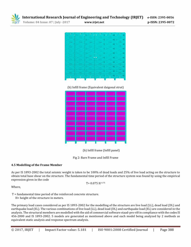
(b) Infill frame (Equivalent daigonal strut)
(b) Infill frame (Infill panel)
Fig 2: Bare Frame and Infill Frame 4.5 Modelling of the Frame Member As per IS 1893-2002 the total seismic weight is taken to be 100% of dead loads and 25% of live load acting on the structure to obtain total base shear on the structure. The fundamental time period of the structure system was found by using the empirical expression given in the code
T= 0.075 H 0.75 Where, T = fundamental time period of the reinforced concrete structure. H= height of the structure in meters. The primary load cases considered as per IS 1893-2002 for the modelling of the structure are live load (LL), dead load (DL) and earthquake load (EL). The various combinations of live load (LL), dead load (DL) and earthquake load (EL) are considered in the analysis. The structural members are modelled with the aid of commercial software staad-pro vi8 in compliance with the codes IS 456-2000 and IS 1893-2002. 5 models are generated as mentioned above and each model being analyzed by 2 methods as equivalent static analysis and response spectrum analysis.

International Research Journal of Engineering and Technology (IRJET) e-ISSN: 2395-0056
Volume: 04 Issue: 07 | July -2017 www.irjet.net p-ISSN: 2395-0072
© 2017, IRJET | Impact Factor value: 5.181 | ISO 9001:2008 Certified Journal | Page 389
4.6 Modelling of Infill Wall Many Investigators have proposed various approximations for the width of equivalent diagonal strut. Smith (1966) proposed a formula to calculate the width of strut based on the relative stiffness of the frame and the infill walls. The width of the strut depends on the length of contact between the wall & the columns (αh) and between the wall & the beams (αL). The formulations for αh and αL
on the basis of beam on an elastic foundation has been given by Stafford Smith(1966).The following equations are used to determine the equivalent or effective strut width Where the strut is assumed to be subjected to uniform compressive stress.
αh=
αL=
w = (αh2 + αL
2)
= tan-1 (H/L).
Where, Em is Elastic Modulus of masonry wall, Ef is Elastic Modulus of masonry of frame material, t is Thickness of the in-fill wall, h is Height of the in-fill wall, L is Length of the in-fill wall, Ic is Moment of Inertia of the column of the frame, Ib is Moment of Inertia of the beam of the frame, θ is tan-1 (h/L) and w is Width of the Equivalent Strut. Holmes: dz/3 Paulay: dz/4 Where dz is the length of equivalent diagonal strut. Dz = ½ ((h) 2+ (L) 2)1/2 h = Height of infill masonry wall L = Length of infill masonry wall And modelled as infill panel. 4.7 Equivalent Width of Diagonal Strut
Table 3: Width (m) of Equivalent Diagonal Strut for different models
Diagonal Strut
Paulay Holmes Smith
Width m m m
Wx 1.18 1.57 1.57
Wz 1.29 1.72 1.64
Where Wx and Wz is the width of Equivalent diagonal strut in longitudinal and transverse direct 5. RESULTS AND DISCUSSION 5.1 Result from Static and Response Spectrum Analysis As mentioned earlier the selected infill masonry building is analysed for following two different cases:
i) Without considering infill strength and stiffness (without infill/bare frame).
ii) Considering infill strength and stiffness (with infill/infilled frame) In total 5 models are considered for analysis as mentioned in the chapter of modelling of proposed problem. Equivalent static analysis of these five building models is carried out to evaluate the effect of infill on the seismic behaviour of infill masonry building for two different cases. Following sections presents the results obtained from these analyses.
International Research Journal of Engineering and Technology (IRJET) e-ISSN: 2395-0056
Volume: 04 Issue: 07 | July -2017 www.irjet.net p-ISSN: 2395-0072
© 2017, IRJET | Impact Factor value: 5.181 | ISO 9001:2008 Certified Journal | Page 390
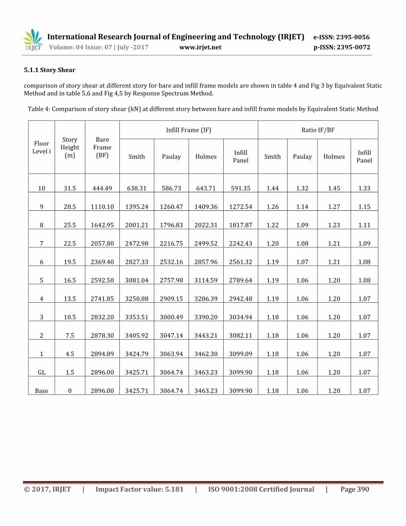
5.1.1 Story Shear comparison of story shear at different story for bare and infill frame models are shown in table 4 and Fig 3 by Equivalent Static Method and in table 5,6 and Fig 4,5 by Response Spectrum Method.
Table 4: Comparison of story shear (kN) at different story between bare and infill frame models by Equivalent Static Method
Floor Level i
Story Height
(m)
Bare Frame (BF)
Infill Frame (IF) Ratio IF/BF
Smith Paulay Holmes Infill Panel
Smith Paulay Holmes Infill Panel
10 31.5 444.49 638.31 586.73 643.71 591.35 1.44 1.32 1.45 1.33
9 28.5 1110.10 1395.24 1260.47 1409.36 1272.54 1.26 1.14 1.27 1.15
8 25.5 1642.95 2001.21 1796.83 2022.31 1817.87 1.22 1.09 1.23 1.11
7 22.5 2057.80 2472.98 2216.75 2499.52 2242.43 1.20 1.08 1.21 1.09
6 19.5 2369.40 2827.33 2532.16 2857.96 2561.32 1.19 1.07 1.21 1.08
5 16.5 2592.50 3081.04 2757.98 3114.59 2789.64 1.19 1.06 1.20 1.08
4 13.5 2741.85 3250.88 2909.15 3286.39 2942.48 1.19 1.06 1.20 1.07
3 10.5 2832.20 3353.51 3000.49 3390.20 3034.94 1.18 1.06 1.20 1.07
2 7.5 2878.30 3405.92 3047.14 3443.21 3082.11 1.18 1.06 1.20 1.07
1 4.5 2894.89 3424.79 3063.94 3462.30 3099.09 1.18 1.06 1.20 1.07
GL 1.5 2896.00 3425.71 3064.74 3463.23 3099.90 1.18 1.06 1.20 1.07
Base 0 2896.00 3425.71 3064.74 3463.23 3099.90 1.18 1.06 1.20 1.07

International Research Journal of Engineering and Technology (IRJET) e-ISSN: 2395-0056
Volume: 04 Issue: 07 | July -2017 www.irjet.net p-ISSN: 2395-0072
© 2017, IRJET | Impact Factor value: 5.181 | ISO 9001:2008 Certified Journal | Page 391
Figure 3: Story shear (kN) at different story for bare and infill frame models by Equivalent Static Method
Table 5: Comparison of story shear (kN) at different story between infill and bare frame models by Response Spectrum Method in Longitudinal Direction
Floor Level i
Story Height
(m)
Bare Frame
Infill Frame Ratio IF/BF
Smith Paulay Holmes Infill Panel
Smith Paulay Holmes Infill Panel
10 31.5 308.28 588.99 542.82 593.72 546.16 1.91 1.76 1.93 1.77
9 28.5 904.3 1485.14 1357.58 1498.74 1358.58 1.64 1.50 1.66 1.50
8 25.5 1397.42 2307.61 2108.47 2329.4 2100.8 1.65 1.51 1.67 1.50
7 22.5 1764.36 3050.88 2789.24 3080.12 2769.48 1.73 1.58 1.75 1.57
6 19.5 2025.59 3710.9 3394.96 3746.83 3362.65 1.83 1.68 1.85 1.66
5 16.5 2236.34 4285.53 3922.41 4327.31 3879.97 1.92 1.75 1.93 1.73
4 13.5 2450.68 4774.67 4370.26 4821.5 4322.94 1.95 1.78 1.97 1.76
3 10.5 2679.53 5180.24 4739.01 5231.29 4695.08 1.93 1.77 1.95 1.75
2 7.5 2883.41 5507.87 5032.71 5562.36 5002.01 1.91 1.75 1.93 1.73
1 4.5 3006.23 5764.64 5256.65 5821.87 5252.13 1.92 1.75 1.94 1.75
GL 1.5 3016.56 5837.29 5314.51 5895.53 5325.92 1.94 1.76 1.95 1.77
Base 0 3016.56 5837.29 5314.51 5895.53 5325.92 1.94 1.76 1.95 1.77

International Research Journal of Engineering and Technology (IRJET) e-ISSN: 2395-0056
Volume: 04 Issue: 07 | July -2017 www.irjet.net p-ISSN: 2395-0072
© 2017, IRJET | Impact Factor value: 5.181 | ISO 9001:2008 Certified Journal | Page 392
Fig 4: story shear (kN) at different story between infill and bare frame models by Response Spectrum Method in Longitudinal Direction
Table 6: Comparison of story shear (kN) at different story between infill and bare frame models by Response Spectrum
Method in Transverse Direction
Floor Level i
Story Height
(m)
Bare Frame
Infill Frame Ratio IF/BF
Smith Paulay Holmes Infill Panel
Smith Paulay Holmes Infill Panel
10 31.5 296.05 624.59 574.31 630.09 546.16 2.11 1.94 2.13 1.84
9 28.5 859.66 1548.8 1411.71 1563.33 1358.58 1.80 1.64 1.82 1.58
8 25.5 1316.06 2371.35 2159.78 2393.26 2100.8 1.80 1.64 1.82 1.60
7 22.5 1644.18 3089.4 2815.14 3117.2 2769.48 1.88 1.71 1.90 1.68
6 19.5 1867.43 3702.16 3376.21 3734.53 3362.65 1.98 1.81 2.00 1.80
5 16.5 2045.31 4211.25 3843.64 4247.08 3879.97 2.06 1.88 2.08 1.90
4 13.5 2235.62 4621.05 4220.55 4659.45 4322.94 2.07 1.89 2.08 1.93
3 10.5 2449.21 4938.7 4512.52 4979.04 4695.08 2.02 1.84 2.03 1.92
2 7.5 2643.44 5175.41 4728.93 5217.36 5002.01 1.96 1.79 1.97 1.89
1 4.5 2760.42 5344.8 4881.22 5388.36 5252.13 1.94 1.77 1.95 1.90
GL 1.5 2770.05 5388.72 4917.74 5433.2 5325.92 1.95 1.78 1.96 1.92
Base 0 2770.05 5388.72 4917.74 5433.2 5325.92 1.95 1.78 1.96 1.92
International Research Journal of Engineering and Technology (IRJET) e-ISSN: 2395-0056
Volume: 04 Issue: 07 | July -2017 www.irjet.net p-ISSN: 2395-0072
© 2017, IRJET | Impact Factor value: 5.181 | ISO 9001:2008 Certified Journal | Page 393
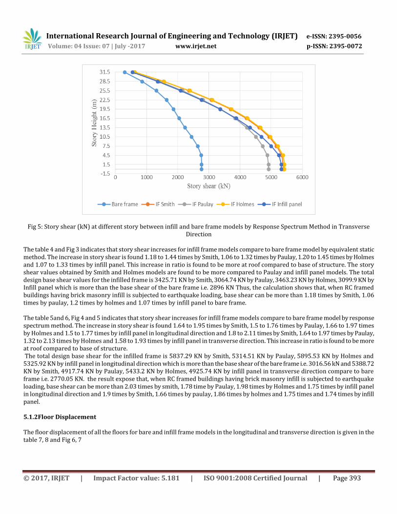
Fig 5: Story shear (kN) at different story between infill and bare frame models by Response Spectrum Method in Transverse Direction
The table 4 and Fig 3 indicates that story shear increases for infill frame models compare to bare frame model by equivalent static method. The increase in story shear is found 1.18 to 1.44 times by Smith, 1.06 to 1.32 times by Paulay, 1.20 to 1.45 times by Holmes and 1.07 to 1.33 times by infill panel. This increase in ratio is found to be more at roof compared to base of structure. The story shear values obtained by Smith and Holmes models are found to be more compared to Paulay and infill panel models. The total design base shear values for the infilled frame is 3425.71 KN by Smith, 3064.74 KN by Paulay, 3463.23 KN by Holmes, 3099.9 KN by Infill panel which is more than the base shear of the bare frame i.e. 2896 KN Thus, the calculation shows that, when RC framed buildings having brick masonry infill is subjected to earthquake loading, base shear can be more than 1.18 times by Smith, 1.06 times by paulay, 1.2 times by holmes and 1.07 times by infill panel to bare frame. The table 5and 6, Fig 4 and 5 indicates that story shear increases for infill frame models compare to bare frame model by response spectrum method. The increase in story shear is found 1.64 to 1.95 times by Smith, 1.5 to 1.76 times by Paulay, 1.66 to 1.97 times by Holmes and 1.5 to 1.77 times by infill panel in longitudinal direction and 1.8 to 2.11 times by Smith, 1.64 to 1.97 times by Paulay, 1.32 to 2.13 times by Holmes and 1.58 to 1.93 times by infill panel in transverse direction. This increase in ratio is found to be more at roof compared to base of structure. The total design base shear for the infilled frame is 5837.29 KN by Smith, 5314.51 KN by Paulay, 5895.53 KN by Holmes and 5325.92 KN by infill panel in longitudinal direction which is more than the base shear of the bare frame i.e. 3016.56 kN and 5388.72 KN by Smith, 4917.74 KN by Paulay, 5433.2 KN by Holmes, 4925.74 KN by infill panel in transverse direction compare to bare frame i.e. 2770.05 KN. the result expose that, when RC framed buildings having brick masonry infill is subjected to earthquake loading, base shear can be more than 2.03 times by smith, 1.78 time by Paulay, 1.98 times by Holmes and 1.75 times by infill panel in longitudinal direction and 1.9 times by Smith, 1.66 times by paulay, 1.86 times by holmes and 1.75 times and 1.74 times by infill panel. 5.1.2Floor Displacement The floor displacement of all the floors for bare and infill frame models in the longitudinal and transverse direction is given in the table 7, 8 and Fig 6, 7
International Research Journal of Engineering and Technology (IRJET) e-ISSN: 2395-0056
Volume: 04 Issue: 07 | July -2017 www.irjet.net p-ISSN: 2395-0072
© 2017, IRJET | Impact Factor value: 5.181 | ISO 9001:2008 Certified Journal | Page 394
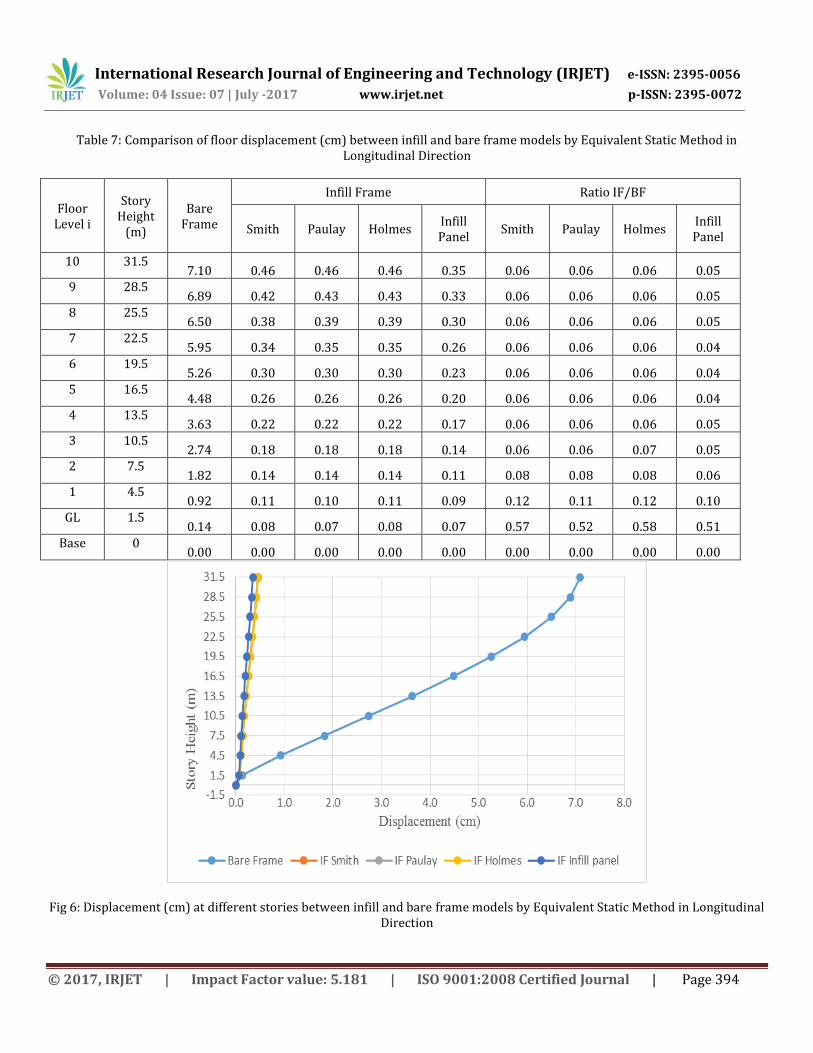
Table 7: Comparison of floor displacement (cm) between infill and bare frame models by Equivalent Static Method in Longitudinal Direction
Floor Level i
Story Height
(m)
Bare Frame
Infill Frame Ratio IF/BF
Smith Paulay Holmes Infill Panel
Smith Paulay Holmes Infill Panel
10 31.5 7.10 0.46 0.46 0.46 0.35 0.06 0.06 0.06 0.05
9 28.5 6.89 0.42 0.43 0.43 0.33 0.06 0.06 0.06 0.05
8 25.5 6.50 0.38 0.39 0.39 0.30 0.06 0.06 0.06 0.05
7 22.5 5.95 0.34 0.35 0.35 0.26 0.06 0.06 0.06 0.04
6 19.5 5.26 0.30 0.30 0.30 0.23 0.06 0.06 0.06 0.04
5 16.5 4.48 0.26 0.26 0.26 0.20 0.06 0.06 0.06 0.04
4 13.5 3.63 0.22 0.22 0.22 0.17 0.06 0.06 0.06 0.05
3 10.5 2.74 0.18 0.18 0.18 0.14 0.06 0.06 0.07 0.05
2 7.5 1.82 0.14 0.14 0.14 0.11 0.08 0.08 0.08 0.06
1 4.5 0.92 0.11 0.10 0.11 0.09 0.12 0.11 0.12 0.10
GL 1.5 0.14 0.08 0.07 0.08 0.07 0.57 0.52 0.58 0.51
Base 0 0.00 0.00 0.00 0.00 0.00 0.00 0.00 0.00 0.00
Fig 6: Displacement (cm) at different stories between infill and bare frame models by Equivalent Static Method in Longitudinal Direction

International Research Journal of Engineering and Technology (IRJET) e-ISSN: 2395-0056
Volume: 04 Issue: 07 | July -2017 www.irjet.net p-ISSN: 2395-0072
© 2017, IRJET | Impact Factor value: 5.181 | ISO 9001:2008 Certified Journal | Page 395
Table 8: Comparison of floor displacement (cm) between infill and bare frame models by Equivalent Static Method in Transverse Direction
Floor Level i
Story Height
(m)
Bare Frame
Infill Frame Ratio IF/BF
Smith Paulay Holmes Infill Panel
Smith Paulay Holmes Infill Panel
10 31.5 8.57 0.83 0.79 0.83 0.64 0.10 0.09 0.10 0.07
9 28.50 8.29 0.75 0.72 0.75 0.57 0.09 0.09 0.09 0.07
8 25.5 7.80 0.66 0.64 0.66 0.51 0.08 0.08 0.08 0.06
7 22.5 7.12 0.57 0.55 0.57 0.44 0.08 0.08 0.08 0.06
6 19.5 6.28 0.48 0.47 0.48 0.37 0.08 0.07 0.08 0.06
5 16.5 5.34 0.40 0.39 0.40 0.30 0.07 0.07 0.07 0.06
4 13.5 4.31 0.32 0.31 0.32 0.24 0.07 0.07 0.07 0.06
3 10.5 3.23 0.24 0.24 0.24 0.19 0.08 0.07 0.07 0.06
2 7.5 2.13 0.18 0.17 0.18 0.14 0.08 0.08 0.08 0.07
1 4.5 1.06 0.13 0.12 0.13 0.10 0.12 0.11 0.12 0.10
GL 1.5 0.16 0.08 0.08 0.08 0.07 0.53 0.48 0.53 0.47
Base 0 0.00 0.00 0.00 0.00 0.00 0.00 0.00 0.00 0.00
Fig 7: Displacement (cm) at different stories between infill and bare frame models by Equivalent Static Method in Transverse Direction
The table 7 and 8 indicate that displacement for infill frame is considerably decrease compare to bare frame. The displacement decreases about 0.06 to 0.57 times by Smith, 0.06 to 0.52 times by Paulay, 0.06 to 0.58 times by Holmes and 0.04 to 0.51 times

International Research Journal of Engineering and Technology (IRJET) e-ISSN: 2395-0056
Volume: 04 Issue: 07 | July -2017 www.irjet.net p-ISSN: 2395-0072
© 2017, IRJET | Impact Factor value: 5.181 | ISO 9001:2008 Certified Journal | Page 396
by infill panel in longitudinal direction while 0.07 to 0.53 times by Smith, 0.07 to 0.48 times by Paulay, 0.07 to 0.53 times by Holmes, 0.06 to 0.47 times by infill panel in transverse direction, the ratio found to be more at base compare to all other story because of discontinuity of infill wall. 5.1.3 Story Drift The comparison of story drift for all storeys between bare and infill frame is given in table 9, 10 and Fig. 8, 9
Table 9: Comparison of Story Drift (cm) at different story between infill and bare frame models by Equivalent Static Method in
Longitudinal Direction
Floor Level i
Story Height
(m)
Bare Frame
Infill Frame Ratio IF/BF
Smith Paulay Holmes Infill Panel
Smith Paulay Holmes Infill Panel
10 31.5 0.209 0.034 0.032 0.034 0.028 0.163 0.155 0.165 0.135
9 28.5 0.387 0.038 0.037 0.038 0.030 0.098 0.096 0.099 0.079
8 25.5 0.552 0.041 0.041 0.041 0.032 0.074 0.073 0.075 0.058
7 22.5 0.683 0.042 0.043 0.043 0.033 0.062 0.063 0.063 0.048
6 19.5 0.781 0.043 0.044 0.043 0.032 0.055 0.056 0.055 0.041
5 16.5 0.850 0.042 0.043 0.042 0.031 0.049 0.051 0.050 0.037
4 13.5 0.894 0.040 0.042 0.040 0.029 0.045 0.046 0.045 0.032
3 10.5 0.916 0.039 0.036 0.040 0.026 0.043 0.039 0.043 0.029
2 7.5 0.907 0.032 0.034 0.032 0.022 0.035 0.038 0.035 0.024
1 4.5 0.778 0.029 0.032 0.030 0.020 0.038 0.042 0.038 0.025
GL 1.5 0.138 0.079 0.071 0.080 0.071 0.572 0.516 0.577 0.513
Base 0 0.000 0.000 0.000 0.000 0.000 0.000 0.000 0.000 0.000
Figure 8: Story Drift (cm) at different story between infill and bare frame models by Equivalent Static Method in Longitudinal Direction

International Research Journal of Engineering and Technology (IRJET) e-ISSN: 2395-0056
Volume: 04 Issue: 07 | July -2017 www.irjet.net p-ISSN: 2395-0072
© 2017, IRJET | Impact Factor value: 5.181 | ISO 9001:2008 Certified Journal | Page 397
Table 10: Comparison of Story Drift (cm) at different story between infill and bare frame models by Equivalent Static Method in Transverse Direction
Floor Level i
Story Height
(m)
Bare Frame
Infill Frame Ratio IF/BF
Smith Paulay Holmes Infill Panel
Smith Paulay Holmes Infill Panel
10 31.5 0.283 0.082 0.076 0.082 0.066 0.288 0.267 0.290 0.232
9 28.50 0.488 0.086 0.080 0.086 0.068 0.175 0.164 0.176 0.139
8 25.5 0.681 0.088 0.083 0.088 0.069 0.129 0.122 0.130 0.101
7 22.5 0.835 0.088 0.084 0.088 0.068 0.105 0.101 0.106 0.081
6 19.5 0.949 0.086 0.082 0.086 0.066 0.091 0.087 0.091 0.069
5 16.5 1.028 0.081 0.079 0.081 0.061 0.079 0.076 0.079 0.060
4 13.5 1.077 0.074 0.072 0.074 0.055 0.069 0.067 0.069 0.051
3 10.5 1.098 0.065 0.059 0.066 0.048 0.059 0.054 0.060 0.043
2 7.5 1.075 0.052 0.052 0.052 0.038 0.049 0.049 0.048 0.035
1 4.5 0.898 0.042 0.044 0.042 0.029 0.047 0.049 0.047 0.032
GL 1.5 0.159 0.084 0.075 0.084 0.074 0.526 0.475 0.531 0.466
Base 0 0.000 0.000 0.000 0.000 0.000 0.000 0.000 0.000 0.000
Fig 9: Story Drift (cm) at different stories between infill and bare frame models by Equivalent Static Method in Transverse Direction
The Table 9 and 10, indicates that the story drift is decreasing in infill frames compare to bare frame. This decrease in story drift is about 0.035 to 0.572 times by Smith, 0.038 to 0.516 times by Paulay, 0.035 to 0.577 times by Holmes and 0.024 to 0.513 times by infill panel in longitudinal direction while 0.047 to 0.526 times by Smith, 0.049 to 0.475 times by Paulay, 0.047 to 0.531 times by
International Research Journal of Engineering and Technology (IRJET) e-ISSN: 2395-0056
Volume: 04 Issue: 07 | July -2017 www.irjet.net p-ISSN: 2395-0072
© 2017, IRJET | Impact Factor value: 5.181 | ISO 9001:2008 Certified Journal | Page 398
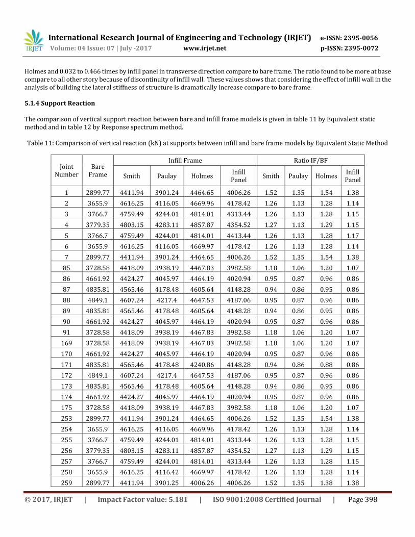
Holmes and 0.032 to 0.466 times by infill panel in transverse direction compare to bare frame. The ratio found to be more at base compare to all other story because of discontinuity of infill wall. These values shows that considering the effect of infill wall in the analysis of building the lateral stiffness of structure is dramatically increase compare to bare frame. 5.1.4 Support Reaction The comparison of vertical support reaction between bare and infill frame models is given in table 11 by Equivalent static method and in table 12 by Response spectrum method. Table 11: Comparison of vertical reaction (kN) at supports between infill and bare frame models by Equivalent Static Method
Joint Number
Bare Frame
Infill Frame Ratio IF/BF
Smith Paulay Holmes Infill Panel
Smith Paulay Holmes Infill Panel
1 2899.77 4411.94 3901.24 4464.65 4006.26 1.52 1.35 1.54 1.38
2 3655.9 4616.25 4116.05 4669.96 4178.42 1.26 1.13 1.28 1.14
3 3766.7 4759.49 4244.01 4814.01 4313.44 1.26 1.13 1.28 1.15
4 3779.35 4803.15 4283.11 4857.87 4354.52 1.27 1.13 1.29 1.15
5 3766.7 4759.49 4244.01 4814.01 4413.44 1.26 1.13 1.28 1.17
6 3655.9 4616.25 4116.05 4669.97 4178.42 1.26 1.13 1.28 1.14
7 2899.77 4411.94 3901.24 4464.65 4006.26 1.52 1.35 1.54 1.38
85 3728.58 4418.09 3938.19 4467.83 3982.58 1.18 1.06 1.20 1.07
86 4661.92 4424.27 4045.97 4464.19 4020.94 0.95 0.87 0.96 0.86
87 4835.81 4565.46 4178.48 4605.64 4148.28 0.94 0.86 0.95 0.86
88 4849.1 4607.24 4217.4 4647.53 4187.06 0.95 0.87 0.96 0.86
89 4835.81 4565.46 4178.48 4605.64 4148.28 0.94 0.86 0.95 0.86
90 4661.92 4424.27 4045.97 4464.19 4020.94 0.95 0.87 0.96 0.86
91 3728.58 4418.09 3938.19 4467.83 3982.58 1.18 1.06 1.20 1.07
169 3728.58 4418.09 3938.19 4467.83 3982.58 1.18 1.06 1.20 1.07
170 4661.92 4424.27 4045.97 4464.19 4020.94 0.95 0.87 0.96 0.86
171 4835.81 4565.46 4178.48 4240.86 4148.28 0.94 0.86 0.88 0.86
172 4849.1 4607.24 4217.4 4647.53 4187.06 0.95 0.87 0.96 0.86
173 4835.81 4565.46 4178.48 4605.64 4148.28 0.94 0.86 0.95 0.86
174 4661.92 4424.27 4045.97 4464.19 4020.94 0.95 0.87 0.96 0.86
175 3728.58 4418.09 3938.19 4467.83 3982.58 1.18 1.06 1.20 1.07
253 2899.77 4411.94 3901.24 4464.65 4006.26 1.52 1.35 1.54 1.38
254 3655.9 4616.25 4116.05 4669.96 4178.42 1.26 1.13 1.28 1.14
255 3766.7 4759.49 4244.01 4814.01 4313.44 1.26 1.13 1.28 1.15
256 3779.35 4803.15 4283.11 4857.87 4354.52 1.27 1.13 1.29 1.15
257 3766.7 4759.49 4244.01 4814.01 4313.44 1.26 1.13 1.28 1.15
258 3655.9 4616.25 4116.42 4669.97 4178.42 1.26 1.13 1.28 1.14
259 2899.77 4411.94 3901.25 4006.26 4006.26 1.52 1.35 1.38 1.38
International Research Journal of Engineering and Technology (IRJET) e-ISSN: 2395-0056
Volume: 04 Issue: 07 | July -2017 www.irjet.net p-ISSN: 2395-0072
© 2017, IRJET | Impact Factor value: 5.181 | ISO 9001:2008 Certified Journal | Page 399
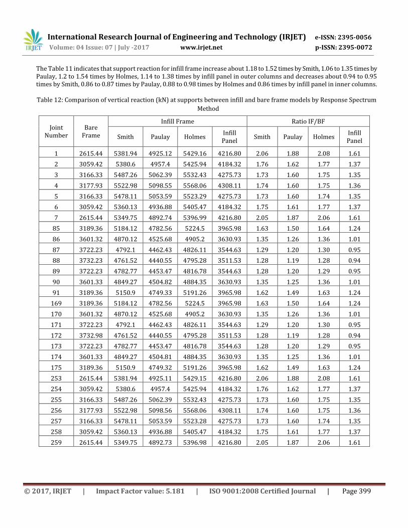
The Table 11 indicates that support reaction for infill frame increase about 1.18 to 1.52 times by Smith, 1.06 to 1.35 times by Paulay, 1.2 to 1.54 times by Holmes, 1.14 to 1.38 times by infill panel in outer columns and decreases about 0.94 to 0.95 times by Smith, 0.86 to 0.87 times by Paulay, 0.88 to 0.98 times by Holmes and 0.86 times by infill panel in inner columns. Table 12: Comparison of vertical reaction (kN) at supports between infill and bare frame models by Response Spectrum
Method
Joint Number
Bare Frame
Infill Frame Ratio IF/BF
Smith Paulay Holmes Infill Panel
Smith Paulay Holmes Infill Panel
1 2615.44 5381.94 4925.12 5429.16 4216.80 2.06 1.88 2.08 1.61
2 3059.42 5380.6 4957.4 5425.94 4184.32 1.76 1.62 1.77 1.37
3 3166.33 5487.26 5062.39 5532.43 4275.73 1.73 1.60 1.75 1.35
4 3177.93 5522.98 5098.55 5568.06 4308.11 1.74 1.60 1.75 1.36
5 3166.33 5478.11 5053.59 5523.29 4275.73 1.73 1.60 1.74 1.35
6 3059.42 5360.13 4936.88 5405.47 4184.32 1.75 1.61 1.77 1.37
7 2615.44 5349.75 4892.74 5396.99 4216.80 2.05 1.87 2.06 1.61
85 3189.36 5184.12 4782.56 5224.5 3965.98 1.63 1.50 1.64 1.24
86 3601.32 4870.12 4525.68 4905.2 3630.93 1.35 1.26 1.36 1.01
87 3722.23 4792.1 4462.43 4826.11 3544.63 1.29 1.20 1.30 0.95
88 3732.23 4761.52 4440.55 4795.28 3511.53 1.28 1.19 1.28 0.94
89 3722.23 4782.77 4453.47 4816.78 3544.63 1.28 1.20 1.29 0.95
90 3601.33 4849.27 4504.82 4884.35 3630.93 1.35 1.25 1.36 1.01
91 3189.36 5150.9 4749.33 5191.26 3965.98 1.62 1.49 1.63 1.24
169 3189.36 5184.12 4782.56 5224.5 3965.98 1.63 1.50 1.64 1.24
170 3601.32 4870.12 4525.68 4905.2 3630.93 1.35 1.26 1.36 1.01
171 3722.23 4792.1 4462.43 4826.11 3544.63 1.29 1.20 1.30 0.95
172 3732.98 4761.52 4440.55 4795.28 3511.53 1.28 1.19 1.28 0.94
173 3722.23 4782.77 4453.47 4816.78 3544.63 1.28 1.20 1.29 0.95
174 3601.33 4849.27 4504.81 4884.35 3630.93 1.35 1.25 1.36 1.01
175 3189.36 5150.9 4749.32 5191.26 3965.98 1.62 1.49 1.63 1.24
253 2615.44 5381.94 4925.11 5429.15 4216.80 2.06 1.88 2.08 1.61
254 3059.42 5380.6 4957.4 5425.94 4184.32 1.76 1.62 1.77 1.37
255 3166.33 5487.26 5062.39 5532.43 4275.73 1.73 1.60 1.75 1.35
256 3177.93 5522.98 5098.56 5568.06 4308.11 1.74 1.60 1.75 1.36
257 3166.33 5478.11 5053.59 5523.28 4275.73 1.73 1.60 1.74 1.35
258 3059.42 5360.13 4936.88 5405.47 4184.32 1.75 1.61 1.77 1.37
259 2615.44 5349.75 4892.73 5396.98 4216.80 2.05 1.87 2.06 1.61
International Research Journal of Engineering and Technology (IRJET) e-ISSN: 2395-0056
Volume: 04 Issue: 07 | July -2017 www.irjet.net p-ISSN: 2395-0072
© 2017, IRJET | Impact Factor value: 5.181 | ISO 9001:2008 Certified Journal | Page 400
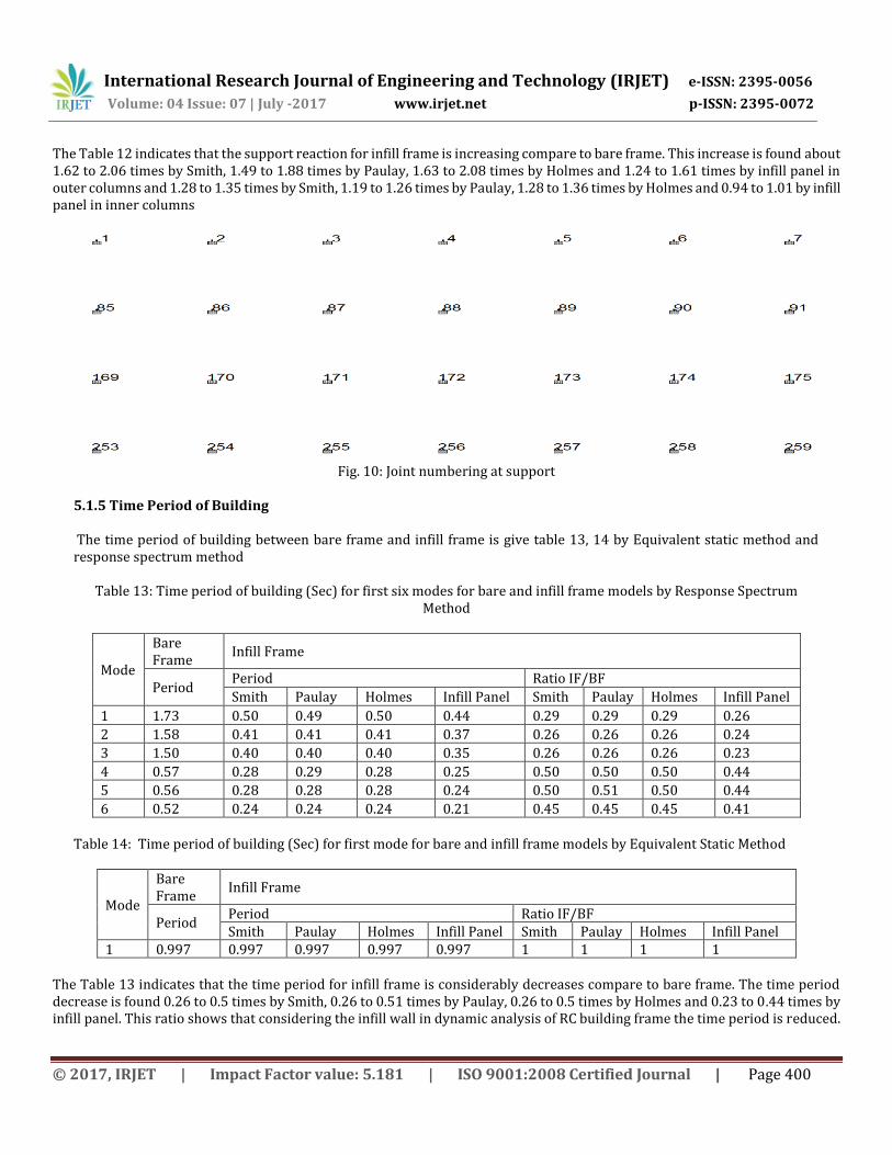
The Table 12 indicates that the support reaction for infill frame is increasing compare to bare frame. This increase is found about 1.62 to 2.06 times by Smith, 1.49 to 1.88 times by Paulay, 1.63 to 2.08 times by Holmes and 1.24 to 1.61 times by infill panel in outer columns and 1.28 to 1.35 times by Smith, 1.19 to 1.26 times by Paulay, 1.28 to 1.36 times by Holmes and 0.94 to 1.01 by infill panel in inner columns
Fig. 10: Joint numbering at support
5.1.5 Time Period of Building The time period of building between bare frame and infill frame is give table 13, 14 by Equivalent static method and response spectrum method
Table 13: Time period of building (Sec) for first six modes for bare and infill frame models by Response Spectrum Method
Mode
Bare Frame
Infill Frame
Period Period Ratio IF/BF
Smith Paulay Holmes Infill Panel Smith Paulay Holmes Infill Panel
1 1.73 0.50 0.49 0.50 0.44 0.29 0.29 0.29 0.26
2 1.58 0.41 0.41 0.41 0.37 0.26 0.26 0.26 0.24
3 1.50 0.40 0.40 0.40 0.35 0.26 0.26 0.26 0.23
4 0.57 0.28 0.29 0.28 0.25 0.50 0.50 0.50 0.44
5 0.56 0.28 0.28 0.28 0.24 0.50 0.51 0.50 0.44
6 0.52 0.24 0.24 0.24 0.21 0.45 0.45 0.45 0.41 Table 14: Time period of building (Sec) for first mode for bare and infill frame models by Equivalent Static Method
Mode
Bare Frame
Infill Frame
Period Period Ratio IF/BF Smith Paulay Holmes Infill Panel Smith Paulay Holmes Infill Panel
1 0.997 0.997 0.997 0.997 0.997 1 1 1 1
The Table 13 indicates that the time period for infill frame is considerably decreases compare to bare frame. The time period decrease is found 0.26 to 0.5 times by Smith, 0.26 to 0.51 times by Paulay, 0.26 to 0.5 times by Holmes and 0.23 to 0.44 times by infill panel. This ratio shows that considering the infill wall in dynamic analysis of RC building frame the time period is reduced.
International Research Journal of Engineering and Technology (IRJET) e-ISSN: 2395-0056
Volume: 04 Issue: 07 | July -2017 www.irjet.net p-ISSN: 2395-0072
© 2017, IRJET | Impact Factor value: 5.181 | ISO 9001:2008 Certified Journal | Page 401
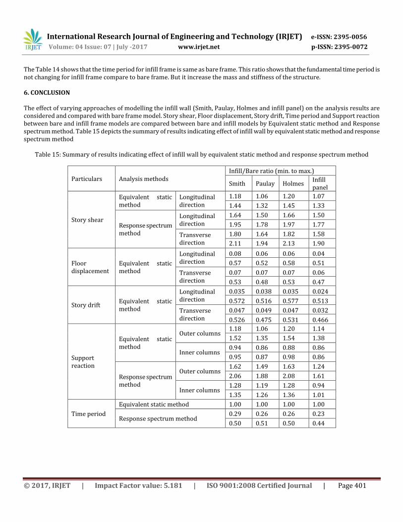
The Table 14 shows that the time period for infill frame is same as bare frame. This ratio shows that the fundamental time period is not changing for infill frame compare to bare frame. But it increase the mass and stiffness of the structure. 6. CONCLUSION The effect of varying approaches of modelling the infill wall (Smith, Paulay, Holmes and infill panel) on the analysis results are considered and compared with bare frame model. Story shear, Floor displacement, Story drift, Time period and Support reaction between bare and infill frame models are compared between bare and infill models by Equivalent static method and Response spectrum method. Table 15 depicts the summary of results indicating effect of infill wall by equivalent static method and response spectrum method
Table 15: Summary of results indicating effect of infill wall by equivalent static method and response spectrum method
Particulars Analysis methods Infill/Bare ratio (min. to max.)
Smith Paulay Holmes Infill panel
Story shear
Equivalent static method
Longitudinal direction
1.18 1.06 1.20 1.07
1.44 1.32 1.45 1.33
Response spectrum method
Longitudinal direction
1.64 1.50 1.66 1.50
1.95 1.78 1.97 1.77
Transverse direction
1.80 1.64 1.82 1.58
2.11 1.94 2.13 1.90
Floor displacement
Equivalent static method
Longitudinal direction
0.08 0.06 0.06 0.04
0.57 0.52 0.58 0.51
Transverse direction
0.07 0.07 0.07 0.06
0.53 0.48 0.53 0.47
Story drift Equivalent static method
Longitudinal direction
0.035 0.038 0.035 0.024
0.572 0.516 0.577 0.513
Transverse direction
0.047 0.049 0.047 0.032
0.526 0.475 0.531 0.466
Support reaction
Equivalent static method
Outer columns 1.18 1.06 1.20 1.14
1.52 1.35 1.54 1.38
Inner columns 0.94 0.86 0.88 0.86
0.95 0.87 0.98 0.86
Response spectrum method
Outer columns 1.62 1.49 1.63 1.24
2.06 1.88 2.08 1.61
Inner columns 1.28 1.19 1.28 0.94
1.35 1.26 1.36 1.01
Time period
Equivalent static method 1.00 1.00 1.00 1.00
Response spectrum method 0.29 0.26 0.26 0.23
0.50 0.51 0.50 0.44

International Research Journal of Engineering and Technology (IRJET) e-ISSN: 2395-0056
Volume: 04 Issue: 07 | July -2017 www.irjet.net p-ISSN: 2395-0072
© 2017, IRJET | Impact Factor value: 5.181 | ISO 9001:2008 Certified Journal | Page 402
The results obtain from the analysis indicates that story shear increase for infill frame models compare to bare frame model by equivalent static method and response spectrum method. This increase in ratio is found to be more at roof compared to base of structure. The story shear values obtained by Smith and Holmes models are found to be more compared to Paulay and infill panel models. The result for floor displacement and story drift obtained by equivalent static method indicate that the displacement and drift for infill frame is considerably decreases compare to bare frame. The time period for infill frame is dramatically decreases compare to bare frame by response spectrum method. The vertical support reaction results obtained from the analysis indicates that the support reaction for infill frame is increasing in outer columns and decreases in inner columns by equivalent static method. The vertical support reaction for infill frame is found to be more in response spectrum method compared to static method. REFERENCES [1]Agarwal P. and Shrikhande M. (2006). Earthquake resistant design of structures. PHI Learning Pvt. Ltd., New Delhi. [2]Al-Chaar G., Issa M. and Sweeney S. (2002). Behaviour of masonry infilled non-ductile RC frames. ASCE Journal of Structural Engineering. 128(8), 1055-1063. [3]Arlekar J.N., Jain S. K. and Murty C.V.R (1997). Seismic response of RC frames buildings with soft first storeys. Proceedings of CBRI golden jubilee conference on natural hazards in urban habitat, New Delhi. [4]Asokan A. (2006). Modelling of Masonry Infill Walls for Nonlinear Static Analysis under Seismic Loads. MS Thesis. Indian Institute of Technology Madras, Chennai. [5]Asteris P. G. (2003). Lateral stiffness of brick masonry infilled plane frames. Journal of Structural Engineering. 129(8), 1071-1079. [6]Chopra A. K. (1973). Earthquake resistance of buildings with a soft first storey. Earthquake and Structural Dynamics. 1, 347-355. [7]Chug R. (2004). Studies on RC Beams. Columns and Joints for Earthquake Resistant Design. M. Tech Project Report. Indian Institute of Technology Madras, Chennai. [8]Crisafulli F. J. (1999). Seismic Behaviour of reinforced concrete structures with masonry infills. Ph.D. Thesis. University of Canterbury, New Zealand. [9]Das S. and Nau J.M. (2003). Seismic design aspects of vertically irregular reinforced concrete buildings. Earthquake Spectra. 19, 455-477. [10]Davis R. (2008). Earthquake Resistant Design of Open Ground Storey RC Framed Buildings. Ph.D. Thesis. Indian Institute of Technology Madras, Chennai. [11]Davis R., Menon D. and Prasad A. M. (2008). Evaluation of magnification factors for open ground storey buildings using nonlinear analyses. The 14th World Conference on Earthquake Engineering, Beijing, China. [12]Deodhar S. V. and Patel A.N. (1998) Ultimate strength of masonry infilled steel frames under horizontal load. Journal of Structural Engineering. Structural Engineering Research Centre. 24, 237-241. [13]Dhansekar M. and Page A.W. (1986). The influence of brick masonry infill properties on the behaviour of infilled frames. Proceedings of Institution of Civil Engineers. Part 2 81, 593-605. [14]Dolsek M. and Fajfar P. (2001). Soft storey effects in uniformly infilled reinforced concrete frames. Journal of Earthquake Engineering. 5(1), 1-12. 15) Dominguez Morales M. (2000). Fundamental period of vibration for reinforced concrete buildings. Canada, University of Ottawa (Canada). [16]Doudoumis I.N. (2006). Finite element modelling and investigation of the behaviour of elastic infilled frames under monotonic loading. Engineering Structures. 29(6), 1004-1024. [17]Dorji J. & Thambiratnam D.P. (2009). Modelling and Analysis of Infilled Frame Structures under Seismic Loads. The Open Construction and Building Technology Journal. 3,119-126. [18]Dukuze A. (2000). Behaviour of reinforced concrete frames infilled with brick masonry panels. Canada, University of New Brunswick (Canada). [19]Fardis M.N. and Panagiotakos T. B. (1997). Seismic design and response of bare and masonry-infilled concrete buildings. Journal of Earthquake Engineering. 1, 475-503. 20) Hashmi A. K. and Madan A. (2008). Damage forecast for masonry infilled reinforced concrete framed buildings subjected to earthquakes in India. Current Science. 94, 61-73. [21]Holmes M. (1961). Steel frames with brick and concrete infilling. Proceedings of Institution of Civil Engineers. 19, 473-478. [22]Jagdish R. and Achyutha H. (1985). Finite element stimulation of the elastic behaviour of infilled frames with openings. Computers & Structures. 23(5), 685-696. [23]Kanitkar R. and Kanitkar V. (2004). Seismic performance of conventional multi-storey buildings with open ground storey floors for vehicular parking. The Indian Concrete Journal. 78, 99-104.

International Research Journal of Engineering and Technology (IRJET) e-ISSN: 2395-0056
Volume: 04 Issue: 07 | July -2017 www.irjet.net p-ISSN: 2395-0072
© 2017, IRJET | Impact Factor value: 5.181 | ISO 9001:2008 Certified Journal | Page 403
[24]Kaushik H.B. (2006). Evaluation of strengthening options for masonry-infilled RC frames with open first storey. Ph.D. Thesis. Indian Institute of Technology Kanpur. [25]Liauw T.C. and Kwan K.H. (1983). Plastic theory of non-integral infilled frames. Proceedings of Institution of Civil Engineers. Part 2, 379-396. [26]Madan A., Reinhorn A.M., Mander J. B. and Valles R.E.(1997). Modelling of masonry infill panels for structural analysis. ASCE Journal of Structural Engineering. 123, 1295–1301. [27]Mainstone R. J. (1971). On the stiffness and strength of infilled frames. Proceedings of Institution of Civil Engineers. Supplementary, 57-90. [28]Mallick D.V. and Severn R.T. (1967). The Behaviour of Infilled Frames under Static Loading. The Institution of Civil Engineers Proceedings. 39, 639-656. [29]Mehrabi A.B., Shing P.B., Schuller M.P. and Noland J. L. (1996). Experimental evaluation of masonry infilled RC frames. ASCE Journal of Structural Engineering. 122, 228-237. [30]Murty C.V.R. (2002). Performance of reinforced concrete frame buildings during 2001 Bhuj earthquake. Proceedings of the
7th
US National Conference on Earthquake Engineering, Boston, USA. Paper no. 745. [31]Murty C. V. R. and Jain S. K. (2000). Beneficial influence of masonry infill walls on seismic performance of RC frame
buildings. Proceedings of the 12th
World Conference on Earthquake Engineering. Paper no. 1790. [32]Parducci A. & Mezzi M. (1980). Repeated horizontal displacements of infilled frames having different stiffness and connection systems – an experimental analysis. 7th World Conference on Earthquake Engineering, Istanbul. [33]Saneinejad A. and Hobbs B. (1995). Inelastic design of infilled frames. ASCE Journal of Structural Engineering. 121, 634-650. BIOGRAPHIES
Nasratullah Zahir is a M. Tech. research Scholar at Department of Civil Engineering, M.A.N.I.T, Bhopal. He is working on “Static and Dynamic Analysis of RC Building frame with Infill”.
Dr. Vivek Garg is an assistant professor in the Department of Civil Engineering, M.A.N.I.T, Bhopal. His specialization is in Structural Engineering, Soil Structure interaction.