static and seismic stability of landfill slopes -...
TRANSCRIPT

82 December 2002 Waste Age WWW.WASTEAGE.COM Waste Age December 2002 83WWW.WASTEAGE.COM
Static and Seismic Stability of
Landfill SlopesBy Timothy Stark, Philip O’Leary and Patrick Walsh
U.S. landfill slope failure occurred in Ohio. Smaller incidents have been asso-ciated with earthquakes [See picture of slope failure on page 83].
It’s important to understand static and seismic slope stability, and how to handle a failure. For example, if a liner is damaged, the waste above that area must be removed and a new liner must be installed. A cover failure requires rein-stallation. When a large quantity of waste becomes unstable, it must be moved over the lined area and re-covered. These remedial actions are expensive.
Design ConsiderationsTo design a landfill for slope stability,
examine the elements that influence sta-bility. Foundation soils must be capable of supporting the landfill’s weight. Failures occur when foundation soils beneath or adjacent to the landfill yield because of the applied load. The applied load corresponds to the material weight above the foundation soils, e.g., the liner system and waste. The placed waste mag-nitude is determined by the unit weight, height and incline. The susceptibility of foundation soils to failure under the applied load can be assessed by routine soil borings and laboratory testing, which measures the shear soil strength. Shear strength refers to the ability of the material to resist structural damage when a force is applied to it, and can be
used in stability analyses. Landfill liner system construction is
important to slope stability. An earthen berm can be constructed at the base of a landfill slope to provide resistance to lateral slope movement in an adjacent cell or undeveloped area. Some slope failures have occurred when the berm was removed during new cell construc-tion and when the berm was not large enough to provide sufficient resistance to lateral slope movement.
A liner system generally consists of one or more soil and/or geosynthetic materials such as geomembranes, geosynthetic clay liners, geonets and geotextiles. Between or above these liners are layers of drainage media comprised of soil or constructed materials. These materials’ shear strength and the interface friction between the layers determine how susceptible the slope is to lateral movement along a geo-synthetic interface in response to forces generated by the waste’s weight.
Sliding along a geosynthetic interface can harm the liner system’s contain-ment function. If sliding occurs below the geomembrane at a compacted clay liner/geomembrane interface, the geo-membrane will stretch and possibly tear. This has occurred in static slope stability failures and in at least one seismic event.
If the geomembrane tears, a leak at the landfill base could occur. This tear may not be detectable from a landfill’s
This is the 11th lesson in the indepen-dent learning correspondence course on municipal solid waste (MSW) landfills. One lesson in this 12-part series will be published in Waste Age each month throughout the year.
If you are interested in taking the course for two continuing education credits (CEUs), send a check (payable to the University of Wisconsin) for $149 to Phil O’Leary, Department of Engineering Professional Development, University of Wisconsin, 432 N. Lake Street, Madi-son, WI 53706. Phone (608) 262-0493. E-mail: [email protected]. Website: www.wasteage.com. Course registration can occur at anytime until December 2006. Previous lessons will be sent to you.
Although the majority of landfills are constructed and operated safely, several slope failures have occurred in U.S. and international landfills.
U.S. failures have occurred at under-construction, operating and closed landfills. Internationally, widely known failures have been at uncontrolled dumps and led to significant loss of life. The most notable accidents were in Turkey and the Philippines. The largest

82 December 2002 Waste Age WWW.WASTEAGE.COM Waste Age December 2002 83WWW.WASTEAGE.COM
surface if the slope does not undergo large, lateral movement. This occurred at a Midwest facility in which the dam-aged geomembrane would not have been uncovered and remediated if the slope toe had not been excavated to connect the geosynthetics of the adjacent cell to the geosynthetics in the existing cell. With large, lateral slope movement, geomembrane damage may be observ-able without excavating waste.
Another potential interface failure occurs when one geosynthetic layer of the liner system slides over another geosynthetic layer. Forces on a geonet placed over a geomembrane liner may cause the geonet to slide along the geo-membrane. The sliding potential can be evaluated by measuring the interface shear strength between the landfill liner using standard direct shear testing [See “Cross Section of Liner System” below]. Each liner system component can slide, depending on the forces applied to it. This can result in material tears or wrinkles. A soil/geosynthetic or a geosynthetic/geosynthetic interface can slide if the interface shear resistance is less than the shear forces induced by the materials above the interface.
The landfill’s top cover system faces similar stability concerns. Some or all of the cover may slide off the waste. As slope incline and length increases, the shear forces caused by gravity increase. The shear forces must be resisted by the shear strength of the weakest soil/geosynthetic or a geosynthetic/geosynthetic interface in the cover system. If the shear forces are greater than the friction of the weakest interface, sliding will occur and lead to geosynthetic tears or slope failure.
It’s important to consider the effec-
tiveness of the drainage layer above the cover system geomembrane to prevent rainfall- or seepage-induced cover system failure.
Additionally, sliding can occur because of the landfill slope height and steepness, and the presence of a weak waste layer, such as sludge. However, the shear strength of municipal solid waste (MSW) generally is high, and the shear forces generated by the waste’s weight rarely overcomes the strength of MSW and leads to waste slope failure. Thus, stability analyses during design should focus on the shear resistance of the soil and geosynthetic materials underlying the waste.
Liner Slope StabilityWhen calculating slope
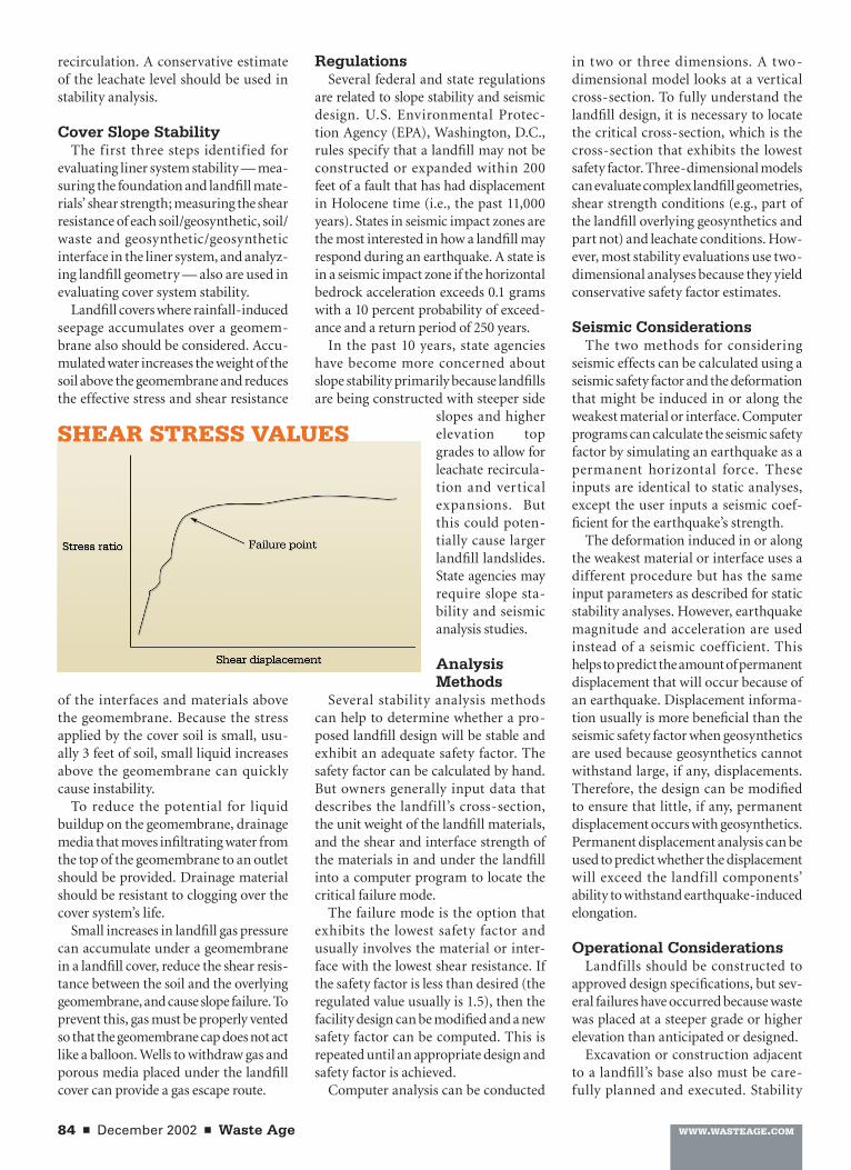
stability, owners should consider the shear strength of the materials in the foun-dation and the landfill. The soil liner, granular drainage media and waste each exhibit a shear strength. Shear strength can be measured in a laboratory by placing a rep-resentative normal stress on the test specimen and shear-ing the specimen into two pieces. The force required to shear the sample is measured and combined with the shear stress measured on identical specimens at other normal stresses. These values are graphed to obtain the material’s failure envelope of [See graph of “Shear Stress Values” on page 84]. If the slope applies shear and normal stress values above the failure envelope, the materials will stretch and/or fail in the field.
Measure the shear resistance of each soil/geosynthetic, soil/waste and geosynthetic/geosynthetic interface in the liner system. This is the available shear resistance to stresses imposed by the overlying landfill slope. For example, each of the liner’s several layers should be tested to determine which is the weakest. Sliding will occur on the weakest inter-face, so the slope should be designed with an adequate safety factor. The evaluation should include the shear resistance or friction between the waste and the liner system’s top layer.
To increase interface strength, manu-facturers have added rough surfaces or
textures into liners. Standard laboratory direct shear devices also can measure shear resistance.
To determine the landfill’s geom-etry, consider the landfill height and slope angle. The slope of the ground upon which the landfill is placed also is important. Increasing height, steeper cover angles, and construction and
steeper slopes must be com-pensated for to insure stability. Berms placed at a landfill’s edge resist waste movement. Increasing berm size can pro-vide more stability. Owners also can specify liner materi-als that are stronger and more resistant to sliding to increase stability. Slope failure-resistant geometry, such as intermediate steps on landfill side slopes, also increase stability.
Leachate level is a consider-able concern during leachate
CROSS-SECTION OF LINER SYSTEM
SLOPE FAILURE: The largest landfill slope failure in the United States occurred in Ohio.
84 December 2002 Waste Age WWW.WASTEAGE.COM Waste Age December 2002 85WWW.WASTEAGE.COM
recirculation. A conservative estimate of the leachate level should be used in stability analysis.
Cover Slope StabilityThe first three steps identified for
evaluating liner system stability — mea-suring the foundation and landfill mate-rials’ shear strength; measuring the shear resistance of each soil/geosynthetic, soil/waste and geosynthetic/geosynthetic interface in the liner system, and analyz-ing landfill geometry — also are used in evaluating cover system stability.
Landfill covers where rainfall-induced seepage accumulates over a geomem-brane also should be considered. Accu-mulated water increases the weight of the soil above the geomembrane and reduces the effective stress and shear resistance
of the interfaces and materials above the geomembrane. Because the stress applied by the cover soil is small, usu-ally 3 feet of soil, small liquid increases above the geomembrane can quickly cause instability.
To reduce the potential for liquid buildup on the geomembrane, drainage media that moves infiltrating water from the top of the geomembrane to an outlet should be provided. Drainage material should be resistant to clogging over the cover system’s life.
Small increases in landfill gas pressure can accumulate under a geomembrane in a landfill cover, reduce the shear resis-tance between the soil and the overlying geomembrane, and cause slope failure. To prevent this, gas must be properly vented so that the geomembrane cap does not act like a balloon. Wells to withdraw gas and porous media placed under the landfill cover can provide a gas escape route.
RegulationsSeveral federal and state regulations
are related to slope stability and seismic design. U.S. Environmental Protec-tion Agency (EPA), Washington, D.C., rules specify that a landfill may not be constructed or expanded within 200 feet of a fault that has had displacement in Holocene time (i.e., the past 11,000 years). States in seismic impact zones are the most interested in how a landfill may respond during an earthquake. A state is in a seismic impact zone if the horizontal bedrock acceleration exceeds 0.1 grams with a 10 percent probability of exceed-ance and a return period of 250 years.
In the past 10 years, state agencies have become more concerned about slope stability primarily because landfills are being constructed with steeper side
slopes and higher elevation top grades to allow for leachate recircula-tion and vertical expansions. But this could poten-tially cause larger landfill landslides. State agencies may require slope sta-bility and seismic analysis studies.
Analysis Methods
Several stability analysis methods can help to determine whether a pro-posed landfill design will be stable and exhibit an adequate safety factor. The safety factor can be calculated by hand. But owners generally input data that describes the landfill’s cross-section, the unit weight of the landfill materials, and the shear and interface strength of the materials in and under the landfill into a computer program to locate the critical failure mode.
The failure mode is the option that exhibits the lowest safety factor and usually involves the material or inter-face with the lowest shear resistance. If the safety factor is less than desired (the regulated value usually is 1.5), then the facility design can be modified and a new safety factor can be computed. This is repeated until an appropriate design and safety factor is achieved.
Computer analysis can be conducted
in two or three dimensions. A two-dimensional model looks at a vertical cross-section. To fully understand the landfill design, it is necessary to locate the critical cross-section, which is the cross-section that exhibits the lowest safety factor. Three-dimensional models can evaluate complex landfill geometries, shear strength conditions (e.g., part of the landfill overlying geosynthetics and part not) and leachate conditions. How-ever, most stability evaluations use two-dimensional analyses because they yield conservative safety factor estimates.
Seismic ConsiderationsThe two methods for considering
seismic effects can be calculated using a seismic safety factor and the deformation that might be induced in or along the weakest material or interface. Computer programs can calculate the seismic safety factor by simulating an earthquake as a permanent horizontal force. These inputs are identical to static analyses, except the user inputs a seismic coef-ficient for the earthquake’s strength.
The deformation induced in or along the weakest material or interface uses a different procedure but has the same input parameters as described for static stability analyses. However, earthquake magnitude and acceleration are used instead of a seismic coefficient. This helps to predict the amount of permanent displacement that will occur because of an earthquake. Displacement informa-tion usually is more beneficial than the seismic safety factor when geosynthetics are used because geosynthetics cannot withstand large, if any, displacements. Therefore, the design can be modified to ensure that little, if any, permanent displacement occurs with geosynthetics. Permanent displacement analysis can be used to predict whether the displacement will exceed the landfill components’ ability to withstand earthquake-induced elongation.
Operational ConsiderationsLandfills should be constructed to
approved design specifications, but sev-eral failures have occurred because waste was placed at a steeper grade or higher elevation than anticipated or designed.
Excavation or construction adjacent to a landfill’s base also must be care-fully planned and executed. Stability
SHEAR STRESS VALUES

84 December 2002 Waste Age WWW.WASTEAGE.COM Waste Age December 2002 85WWW.WASTEAGE.COM
analysis should be conducted before the base is removed or excavated to ensure that structural integrity is maintained. Additionally, excavation should be lim-ited and filled in prior to extending the excavation along the slope’s toe.
Water will influence slope stability. Increasing water quantities increase the waste’s unit weight, which means more driving force pushes on the liner system and foundation soils. Additional liquid could result in effective stress reductions. Waste with higher moisture content may reduce shear strength.
How waste is placed in a landfill also influences slope stability. High-density waste will increase the forces on the liner and foundation soils. Vertical expansions can lead to slope failure by inducing too high driving forces along a geosynthetic interface or through a foundation soil. A simple scenario for this type of overloading is placing a large amount of material over the landfill in a short period for stockpiling purposes or prior to final closure. Over-filling (placing waste in excess of the permit-ted volume) can cause slope failure.
Site Inspection Slope failure may occur without
warning, but sometimes cracks in landfill cover soils or materials are observed prior to failure. Generally, cracks in landfill cover soils result from settlement and are associated with waste decomposition and con-solidation. Tension cracks can occur when waste moves due to instability. Astute field personnel must distin-guish between sett lement cracks, which do not threaten stability, and tension cracks, which are indicative of slope instability.
In general, settlement cracks do not reappear in the same location in a short period, whereas tension cracks can. Tension cracks should be monitored to assess the slope’s behavior to determine whether the sliding rate is increasing or decreasing. Owners should look for these cracks at the crest (the point where the side and cover meet) of the landfill cells. Another warning sign is when gas wells move out of alignment.
If the ground next to the landfill appears to be rising upward slowly, this could indicate that slope move-ment or failure is occurring.
Emergency ActionsIn some cases, potential slope failure
can be prevented by reducing risk. The options may be limited, but certain procedures can help. First, immediately stop placing waste in the area that may be involved in the failure. If practical, move the waste to reduce additional loading on the failing slope. Waste should be removed after soil material that is adding to the downward forces on the slope and to buttress the base of the slope is removed. Add soil at the landfill base
to prevent landfill movement. If a slope stability failure is a concern,
immediately seek advice from an expert because slope failures usually occur rapidly and with little or no warning. Thus, personnel and equipment can be adversely impacted.
Phil O’Leary and Patrick Walsh are solid waste specialists with the University of Wisconsin-Madison. Timothy Stark is with the University of Illinois’ department of civil engineering.
30
� �����������������������������������������
� ���������������������������
� ������������������������������������������������������������
� ���������������������������������� ������
� ��������������������������
�����������������
�����
��������������������������������������������������������������������������������������������
����������������������������������������������������������������������
�������������������������������������������������������������������