static frequency converter - irgreenri.gov.in at railway's international...sfc feeding concept...
TRANSCRIPT
, OCTOBER 27-28, 2017
Static Frequency Converter International Conference on
GREEN INITIATIVES & RAILWAY ELECTRIFICATION
Hotel Le Meridien, New DelhiArunav Kumar Jha, ABB FACTS
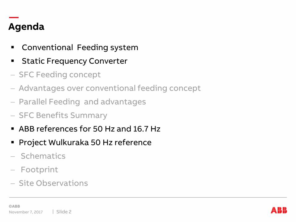
Conventional Feeding system
Static Frequency Converter
SFC Feeding concept
Advantages over conventional feeding concept
Parallel Feeding and advantages
SFC Benefits Summary
ABB references for 50 Hz and 16.7 Hz
Project Wulkuraka 50 Hz reference
Schematics
Footprint
Site Observations
November 7, 2017 Slide 2
Agenda

Typical Railway Power Supply Connection 25 KV, 50Hz
Conventional Feeding System
November 7, 2017 Slide 3
Simple solution but with drawbacks
– Neutral sections due to connection to different electrical phases
– Non optimal catenary voltage
– High catenary short circuit current
– Power flow cannot be controlled and regenerative energy cannot be captured in the system
– Higher peak demands, lower overall traction system efficiency
– Unbalance effect on public grid
– High harmonics injected into supply grid from traction vehicles
– High voltage fluctuations in feeding grids caused by fluctuations of railway loads
– Need for reactive power compensation equipment for fulfilling Grid code requirements
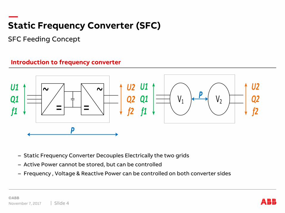
– Static Frequency Converter Decouples Electrically the two grids
– Active Power cannot be stored, but can be controlled
– Frequency , Voltage & Reactive Power can be controlled on both converter sides
SFC Feeding Concept
Static Frequency Converter (SFC)
November 7, 2017 Slide 4
Introduction to frequency converter
~=
~=
P
U1Q1f1
U2Q2f2
PU1Q1f1
U2Q2f2
V1 V2

SFC Feeding System Connection 50Hz
SFC feeding system & Conventional Feeding System
November 7, 2017 Slide 5
Key benefits
– No Neutral zone, continuous power feeding to train
– Parallel & synchronized feeding, increased availability
– Catenary voltage improvements, increased torque capability
– Improved corridor performance, higher overall system efficiency
– Optimized use of regenerative breaking
– Reduction of peak demand
– Excellent short circuit behavior, low fault current contribution
– Fully balanced load, at desired power factor, low harmonic contribution

SFC Feeding Concept :Parallel Feeding 1/2
Static Frequency Converter (SFC)
Optimized Use of Regenerative Breaking Energy

C B A
C B A
BCCAABABABAB AB
Feed
er St
atio
n
Feed
er St
atio
n
Sect
ioni
ng C
abin
Sect
ioni
ng C
abin
Feed
er St
atio
n
Sect
ioni
ng C
abin
C B A
C B AC B ASF
C
C B ASF
C
C B A
BCCA
Feed
er St
atio
n
Feed
er St
atio
n
Sect
ioni
ng C
abin
C B A
kV
Load dependent voltage fluctuation
Excellent line voltage regulation
Wider capture of regenerative braking
Static Frequency Converter (SFC)
SFC Feeding Concept Parallel Feeding 2/2

Power supply scenario
Railway system simulation
Substation A Substation B Substation C
SFC SFC SFC SFC SFC SFC
Substation A Substation B Substation C
Substation A Substation B Substation C
SFC SFC SFC SFC SFC SFC
Substation A Substation B Substation C
Neutral zone “seperated” Neutral zone “connected”Switch circuit “open”Switch circuit “close”
Normal supply scenario Degraded supply scenario
• With SFC No neutral zone
• Smooth take over from other connected SFCs in case of any sub station down
• Smooth and synchronized re-connection as soon as Faulty substation back in operation
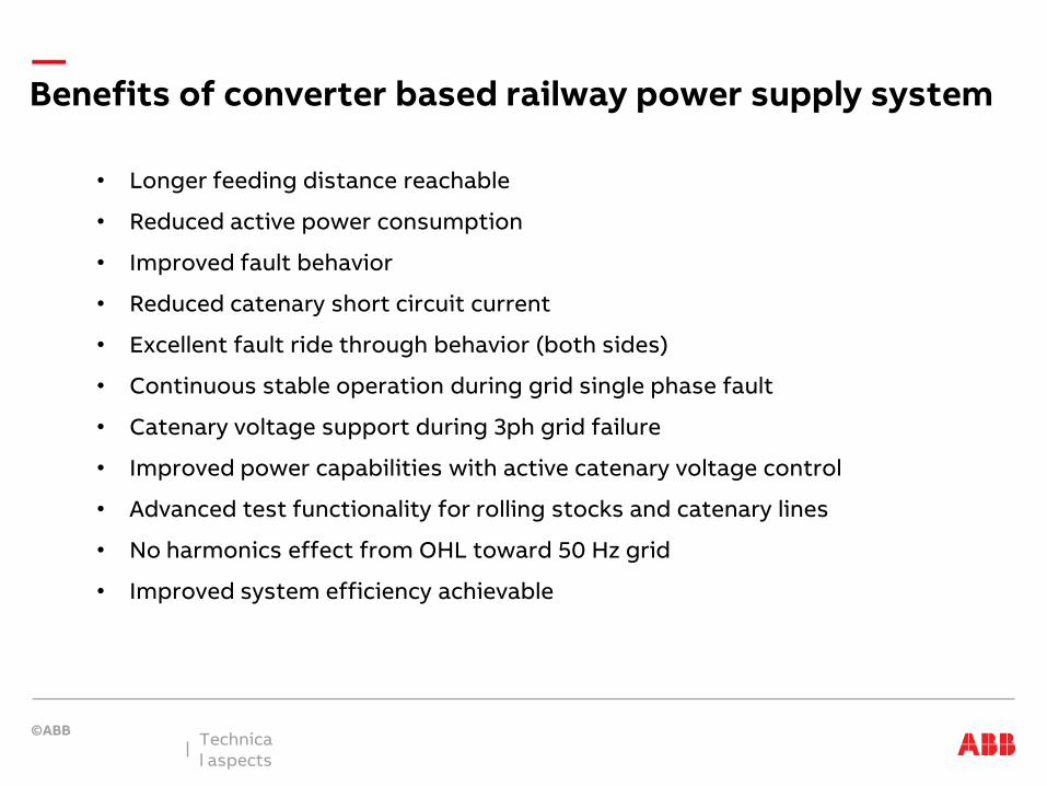
Benefits of converter based railway power supply system
• Longer feeding distance reachable
• Reduced active power consumption
• Improved fault behavior
• Reduced catenary short circuit current
• Excellent fault ride through behavior (both sides)
• Continuous stable operation during grid single phase fault
• Catenary voltage support during 3ph grid failure
• Improved power capabilities with active catenary voltage control
• Advanced test functionality for rolling stocks and catenary lines
• No harmonics effect from OHL toward 50 Hz grid
• Improved system efficiency achievable
Technical aspects

Reference list of ABB SFCs
ABB’s Expereince with SFC Technology Delivery
November 7, 2017 Slide 10
• Largest installed base / more than 40units in service, more than 1.2 GW SFC installed power
• More than 20 years of experience in applications for rail power supply
• Proven control and protection algorithms for 50 Hz and 16 Hz
• Satisfies high reliability and availability demands
• For 50 Hz:
• Wulkuraka, Queensland Rail, AU 1x 16MVA, commissioned in 2016
• Potteric Car, Network Rail, UK awarded in May 2017, 1x42 MVA
Title
PCS6000 16Hz References
Kalix 2x19MVA
Stavanger 2x17MVA
Rudshögda 1x15MVA
Alnabru 2x15MVA
Holmlia 1x15MVA
Larvik 1x15MVA
Neumünster 2x35MVA
Lübeck 2x19MVA
Bremen III 1x40MVA
Bremen II 1x80MVA
Datteln 4x120MVA
Wolkramshausen 2x19MVA
Doberlug 2x19MVA
Düsseldorf 1x19MVA
Hof 2x15MVA
Limburg 8x19MVA
Neckarwestheim 2x75MVA
Timelkam 2x37MVA
Landquart 1x20MVA
Bever 1x20MVA
Obermatt 1x10MVA
Wimmis 4x21MVA
First 50 HZ reference in UK: PottericCar

Reference project Wulkuraka
Converter single line diagram
~~
=
=
~~
=
~~
=
~~
=
~~
3-Phase110kV 50Hz
I
~~
=
~~
=
Filt
er
1-phase25kV 50Hz
I
50 H
z 1p
hIn
vert
er
1ph
tran
sfor
mer
DC
Link
50 H
z 3p
hA
ctiv
e re
ctifi
er
3ph
tran
sfor
mer

Reference project Wulkuraka, Queensland Rail
Customer needsBrisbane – Rosewood lineIncreased energy demand on the tracknew rolling stock maintenance depot nearby25 kV 50 Hz substation without unbalance effects
ABB ResponseTurnkey solution incl. 20 MVA Static frequency converter incl. control, transformers, switchgears,
cooling, filters, installation and commissioning
110 kV 50 Hz 3ph ↔ 25 kV, 50 Hz 1-Ph
Customer’s benefitsStronger railway corridor performance
Introduction

Reference project Wulkuraka, Queensland Rail
Layout 30m x 20m

Reference project Wulkuraka
Installation on site

50:50 Hz Wulkuraka Queensland Rail
ABB’s experience with SFC Technology
November 7, 2017 Slide 15
First Level
– Second Level
• Third Level
• Fourth Level
• Fifth Level
Peak demand reduction
Measured by customer @ Wulkuraka in 2016
Scope is to corridor performance
Reduced energy billings
Use will enhance further on when new fleet is in operation producing more regenerative energy
Peak Demand20% reduction
Wulkuraka SFC
Corinda Tx
Corridor
