status in wales 40 v1 .pdf · common activity spaces volume 1: public areas 1995 status in wales...
TRANSCRIPT

For queries on the status of this document contact [email protected] or telephone 029 2031 5512
Status Note amended March 2013
HEALTH BUILDING NOTE 40
Common activity spaces Volume 1: Public areas
1995
STATUS IN WALES
ARCHIVED
This document was superseded by Health Building Note 00-02
Sanitary spaces 2008
And
Health Building Note 00-04
Circulation and communication spaces 2007

HealthBuilding Note 40
Volume 1 : Public areas
Common activity spaces
London : HMSO

© Crown copyright 1995Applications for reproduction should be made toHMSO Copyright UnitFirst published 1995
ISBN 0 11 322184 3
HMSOStanding order service
Placing a standing order with HMSO BOOKS enables acustomer to receive future titles in this series automaticallyas published. This saves the time, trouble and expense ofplacing individual orders and avoids the problem ofknowing when to do so. For details please write to HMSOBOOKS (PC 13A/1), Publications Centre, PO Box 276,London SW8 5DT quoting reference 05.03.010. Thestanding order service also enables customers to receiveautomatically as published all material of their choice whichadditionally saves extensive catalogue research. The scopeand selectivity of the service has been extended by newtechniques, and there are more than 3,500 classifications tochoose from. A special leaflet describing the service in detailmay be obtained on request.

About this publication
The Health Building Note (HBN) seriesis intended to give advice on thebriefing and design implications ofDepartmental policy.
These Notes are prepared inconsultation with representatives ofthe National Health Service andappropriate professional bodies.
Health Building Notes are aimed atmultidisciplinary teams engaged in:
designing new buildings;•
• adapting or extending existingbuildings.
Throughout the series, particularattention is paid to the relationshipbetween the design of a givendepartment and its subsequentmanagement. Since this equation willhave important implications for capitaland running costs, alternativesolutions are sometimes proposed.The intention is to give the readerinformed guidance on which to basedesign decisions.
spaces that frequently occur incommon form in health buildings.Other Health Building Notes, dealingwith specific departments, refer toHBN 40 for guidance on thesecommonly occurring spaces.
The four volumes of HBN 40 identifiedby the general title ‘Common activityspaces’ bring together guidance on

Acknowledgments
The Royal National Institute for the
Bl ind.
Access Committee for England(extract from HBN 40, Volume 4,
1988/9)

Contents
About this publicationAcknowledgements
1. Scope of Health Building Note 40,Volume 1 page 3
1 .1 Introduction1.10 Capital Investment Manual1.10 Cost allowances1.12 Equipment1.13 Works Guidance Index
2. Design and functional considerations page 5
2.1 Introduction2.2 Disabled people2.8 Statutory and other requirements2.10 Privacy2.11 Fire precautions2.13 Upgrading, extending or adapting existing buildings2.18 Building components2.19 Maintenance and cleaning2.19 Damage in health buildings2.21 Signposting2.22 External environment-parking areas and courtyards2.26 Circulation spaces2.28 Doors2.29 Windows2.30 Natural and artificial lighting2.3 1 Internal spaces2.32 Ventilation2.33 Flooring2.34 Fittings2.35 Information technology2.37 Security2.38 Portering2.39 Smoking
3. Critical dimensions page 1 13.1 Introduction3.2 Component dimensions3.3 Activity dimensions3.4 Selection of activity dimensions3.5 Examples
4. Engineering services page 734.1 Introduction4.3 Model specifications4.4 Economy4.7 Activity data4.8 Safety4.9 Fire safety4.10 Noise4.11 Space for plant and services4.15 Access to control and isolation devices4.16 Engineering commissioning
Mechanical services page 144.17 H e a t i n g4.21 V e n t i l a t i o n4.26 Hot and cold water services
Electrical services page 154.31 Electrical installation4.33 Electrical interference4.36 Lighting4.41 Emergency electrical supplies4.42 Patient/staff and staff/staff call systems4.43 Internal drainage4.44 Design parameters
5. Cost information page 175.1 Introduction5.3 Works cost5.5 Functional units
5.6 Toilets5.7 Bathrooms5.8 Showers
5.9 Dimensions and areas5.12 Circulation areas5.13 Communication routes5.14 Engineering servicesSchedule of Accommodation
6. Example layouts page 20
6.1 Ambulant people page 20Person 1, walking - circulating and passingPerson 2, walking with assistancePerson 3, with walking sticks or tripodsPerson 4, with crutch or crutchesPerson 5, with walking frame
6.2 Wheelchairs page 26Wheelchair 1, straight movementWheelchair 2, turning 90°Wheelchair 3, turning 90° and 180°Wheelchair 4, reachWheelchair 5, dimensions and eye levels
6.3 Building approach page 32Car parking 1, easy accessCar parking 2, wheelchair accessDropped KerbRampExternal Steps
6.4 Doors and lobbies page 47Doors 1, Single leaf, flushDoors 2, Door handles and vision panelsDoors 3, Ironmongery

Lobbies 1, Single leaf doorsLobbies 2, Double leaf doorsLobbies 3, Automatic sliding doors
6.5 Circulation and orientation page 57Signposting 1, eye levels/focal distancesSignposting 2, viewing distances/heightSignposting 3, viewing distances/widthInternal stairsCorridorsHandrailGrabrail
6.6 Toilets page 71Toilets 2, Ambulant, semi- and assisted ambulant -frontal accessToilets 3, Ambulant, semi- and assisted ambulant -lateral accessToilets 4, Independent wheelchair users, with basinToilets 5, Independent and assisted wheelchair users,with basinToilets 6, Dual assisted wheelchair users, with basinToilets 7, WC with bidet and basin
6.7 Waiting/refreshment areas page 79Chair 1, UprightChair 2, High seat easy chairTable 1, Dining, general -ambulant usersTable 2, Dining, general-wheelchair usersTable 3, Dining, square-ambulant usersTable 4, Dining, square -wheelchair usersTable 5, Dining, rectangular-wheelchair usersTable 6, Dining, rectangular-ambulant usersTable 7, Dining, square-ambulant usersTable 8, Dining, round-ambulant users
6.8 Components page 90Basin 1, HandrinseBasin 2, MediumBasin 3, Handrinse (Wheelchair)Basin 4, Medium (Wheelchair)Taps 1, BasinTaps 2, BasinTaps 3, BasinTelephoneMirror 1, Wheelchair usersMirror 2, Grooming, head and shouldersMirror 3, Grooming and dressing, whole bodyWindows 1, Standing and seated usersWindows 2, Wheelchair users and patients in bed
Appendix 1 Healthcare premises: checklist ofaccess and facilities for disabledpeople page 706
Appendix 2 References page 108
Appendix 3 Further reading page 111
Appendix 4 Activity Data page 112
Appendix 5 Index of Ergonomic Data Sheets inother volumes of HBN 40 page 114
Other publications in this series page 111
About NHS Estates page 118

1.0 Scope of Health Building Note 40, Volume 1
Introduction
1.1 This document is the first volume of Health BuildingNote 40, ‘Common activity spaces’, which providesguidance on activity spaces frequently occurring in commonform in health buildings. The previous issues of HBN 40were Volumes 1 and 2 in February 1985, and Volumes 3and 4 in 1988. All four volumes of HBN 40 have now beenrestructured and updated to reflect the latest thinking oncommon activity spaces in health buildings and to provideguidance on access provisions for disabled people to thesebuildings.
1.2 This volume - Volume 1 (Public areas) - providesdetailed ergonomic data on a variety of public spaces, and isrelated to information in Activity Data Sheets specificallyprepared to complement this volume. It aims to provide theessential information with which the designer may producethe most effective and efficient solution for a particularproject.
1.3 Volume 2 (Treatment areas) provides detailedergonomic data on a variety of clinical and sanitary spacesand associated components, and is related to information inActivity Data Sheets specifically prepared to complementthat volume.
1.4 Volume 3 (Staff areas) provides detailed ergonomicdata on a variety of administrative and support spaces andassociated components, and is related to information inActivity Data Sheets specifically prepared to complementthat volume.
1.5 Volume 4 (Circulation areas) deals with internalhorizontal and vertical hospital circulation andcommunication spaces (that is, corridors, lifts and stairs). Itprovides guidance on the planning and design of trafficroutes both within and between hospital departments.Particular emphasis is given to the space requirements forthe movement of people, goods and equipment.
1.6 This guidance relates space provision to the functionsof an activity space, having regard at all times to the needfor economy. Where design teams use this information todetermine space layouts and sizes, the need for economyshould always be a prime consideration so that maximumadvantage can be obtained from the departmental costallowance. Activities should be carefully considered so thatspace can be shared for similar activities or for activitieswhich take place at different times.
of that space, but instead there will be a cross-reference tothat building note. Where there are special departmentalrequirements which warrant a variation from the commonform of the activity space, appropriate information isprovided in the relevant building note.
1.8 In the text of this volume, documents are mainlyreferred to by their title only. Full details of these documentsare included in the ‘References’, which constitute Appendix2 of this volume.
1.9 Details of other relevant publications, research andassociated material which may be of interest for furtherreading are contained in Appendix 3 of this volume.
Capital Investment Manual
1.10 The Capital Investment Manual (England and Wales;in Scotland see ‘Health Building Procurement in Scotland’)contains the NHS Executive’s procedural frameworkgoverning the inception, planning, processing and controlof individual health building schemes. Although there arevarious mandatory requirements within the overall process,the individual NHS trusts are, in the main, granted a certaindegree of flexibility in the manner in which these tasks areto be carried out; however, approval from the NHSExecutive for business cases will depend on how the trustsintend to carry out the mandatory tasks. The Manual givesguidance on the technical considerations of the full capitalappraisal process, while also providing a framework forestablishing management arrangements to ensure that thebenefits of every investment are identified, realised andevaluated. It emphasises three key points:
l each individual scheme must be supported by a soundbusiness case. A business case must convincinglydemonstrate (by means of an option appraisal) thatthe investment is economically sound and financiallyviable (that is, affordable to the trust and itspurchasers);
l an exploration of private finance alternatives shouldbe viewed as a standard option whenever a capitalinvestment scheme is being considered. Once theOutline Business Case has been approved, thepreferred option should be compared to potentialprivate finance alternatives. Approval to the FullBusiness Case will not be given unless there is a cleardemonstration that private finance alternatives havebeen adequately explored;
1.7 Where a common activity space occurs in the buildingnote for a department, there will be no detailed description
• the delivery of a major capital project is a difficult andcomplex task. Nevertheless, any failure to deliver ontime and to cost will divert resources from directpatient care. The establishment of an appropriateproject control/monitoring system and organisation isessential, in order to ensure that projects are deliveredwithin the agreed budgets and timescales.
Cost allowances
1.11 The DCAGs (Departmental Cost Allowance Guides)associated with Volumes 1 to 3 of this Health Building Noteare promulgated in Quarterly Briefing (issued separatelyunder cover of an Estate Policy Letter) on behalf of the NHSExecutive.
Equipment
1.12 The equipment used in the areas covered by thisvolume (that is, the public areas of a health building) can becategorised into four groups, as follows:
Group 1: items (including engineering terminal outlets)which are supplied and fixed within the terms of thebuilding contract;
Group 2: items which have specific requirements withregard to space and/or building construction and/orengineering services and are fixed within the terms of thebuilding contract but supplied under arrangementsseparate from the building contract;
Group 3: as Group 2, but supplied and fixed (or placed inposition) under arrangements separate from the buildingcontract;
Group 4: items which are supplied under arrangementsseparate from the building contract, possibly with storageimplications but otherwise having no effect on therequirements for space or engineering services.
Works Guidance Index
1.13 The guidance contained in this volume is currentat the time of publication. (Specific issues, such asarrangements for dealing with fire, security, energyconservation, etc., are covered by other publisheddocuments, which must also be taken into account.) Someaspects of this guidance may from time to time be amendedor qualified. Project teams should check the current editionof the Works Guidance Index. Because the Index ispublished annually, project teams should ensure that theyare using the current edition, and should contact NHSEstates Library should the need arise to check any items.
2.0 Design and functional considerations
Introduction
2.1 The guidance in this document is intended to enablehealth buildings to be designed which are accessible, safeand usable by all potential categories of user; these willinclude children, an increasing number of elderly people,also patients and visitors who have mobility, sensory anddexterity impairments, and staff. (It must be stressed thathealthcare buildings are places of work for people withdisabilities.) These physical limitations impose specialdemands on the internal and external design of healthbuildings. Specific considerations include the following.
Disabled people
a.2.2 Identifying and understanding the conditions whichconstitute barriers to those with a disability (this categoryincludes, besides the wheelchair-bound, those who for anyreason have difficulty in walking, also those with a sensory -that is, visual or hearing -impairment) is a fundamentalrequirement for the effective provision of accommodationand facilities to be used by disabled people. It is advisable toconsult with all groups of potential users of the building(including people with disabilities and staff from alldepartments) at the early planning stage.
b.
2.3 If the needs of people who have temporary orpermanent disabilities are taken into consideration, theresulting design can make the building easier and safer touse for those with children, those using wheeled equipmentand those carrying other items. The principle of applyingcritical criteria should be used -for example, where space isa consideration, wheelchairs or other larger wheeled itemsneed to be considered; for vertical fixtures or fittings theshorter person and wheelchair user must be considered;and for wayfinding those with visual and hearingimpairments must be considered. The resulting design willhelp not only people who are ill or disabled but also thosewho are suffering from shock or stress, as many users ofhealth buildings are. Building design which givesconsideration to all users will also be easier and safer to useduring an emergency evacuation.
c.
2 .4 The best design philosophy is to consider the journeythrough the health building from start to finish, analysing allthe related components of the task (negotiating entrances,corridors, lifts, reception areas, toilets, etc) to ensure thatthe features, equipment and fittings encountered incompleting the journey are suitably designed so that theoverall task can be completed easily and conveniently,bearing in mind the different requirements of staff, patientsand visitors with varying degrees of functional mobility. In
this way, building users will be more independent (lessreliant upon staff) and consequently less stressed, anxiousand frustrated.
2.5 People with disabilities can be defined as those who,as a consequence of an impairment, may be restricted orinconvenienced in their access to, and use of, buildingsbecause of the physical barriers, such as doors which are toonarrow, or flights of steps, or unsuitable facilities (such asinadequate lighting, or lack of handrails on staircases orgrabrails in toilets). Some people will be temporarilydisabled as a result of their need for hospital treatment.
2.6 The following categories of building user are generallyrecognised:
fully-ambulant: persons who are fully physicallycapable of carrying out all activities necessary to theirrole or function;
semi-ambulant: persons who walk with difficulty orare otherwise insecure, as a result of a temporary orpermanent impairment of the lower limbs. They maywalk with or without a walking aid (sticks, crutches,walking-frames, etc) and/or require the assistance ofanother ambulant person. Some people in thiscategory will, in addition, have reduced strength anddexterity in the upper body and/or a sensoryimpairment. Semi-ambulant people find it difficult tocover long distances (even 50 m may be too far).Specific design requirements include: short distances;provision of handrails and suitable places for taking arest; also even and non-slippery surfaces without anymajor changes in level;
non-ambulant: persons who temporarily orpermanently require to use a wheelchair for mobility.They may propel themselves, or be pushed andmanoeuvred by an assistant who may or may not beneeded to assist with other tasks. Some people will beusing a wheelchair for the first time due to being inhospital and will be unfamiliar with manoeuvring it.Some people who use wheelchairs will, in addition,have reduced strength and dexterity in the upperbody and/or may also have a sensory impairment.Some will be able to stand on their feet whilsttransferring to and from a wheelchair or to and fromother facilities (such as a toilet, chair or bed); otherswill require assistance to do so (in some cases the useof a hoist). Specific design requirements include theprovision of sufficient space for passing and turning;even surfaces without changes in level; and ensuringthat any counters, signs, handles, etc are within theuser’s range of vision and grasp;
d. manually-impaired: persons who have a temporaryor permanent lack of strength and/or dexterity in theshoulders, arms and/or hands. They may also be semi-ambulant and/or have a sensory impairment. Specificdesign requirements include doors which are not tooheavy; suitably-designed handrails and controls, etc;
e . visually-impaired: persons who are totally blind orpartially-sighted. Blind people find their way bynoticing changes in the textures of floor and wallsurfaces and ambient sounds and smells; some alsoneed the help of a cane for orientation and fordetecting obstacles. Partially-sighted people needplenty of light, and the colours of any fixtures andfittings they are trying to locate (or are on their guardagainst) must stand out plainly in contrast with thebackground. It must be remembered that visiondeteriorates considerably with age; 40-year-olds needtwice as much light and 60-year-olds three times asmuch light to see the same object as clearly as a 20-year-old. The more strongly an object contrasts withits surroundings, the easier it is to see. However,colours do not have to be garish; subtle changes incolour can be aesthetically pleasing, and can fit inwith the general decor as well as providing contrast.Different colours in the same tone can appear verysimilar to people who are colour-blind -for example,a strong red and green together can look much thesame-and so contrasting tones, or a combination oftone and colour, are very helpful for people with poorsight. Any type of cluttered design should be avoided,since this makes it more difficult for a visually-impaired person to “read” the shape of a space, andconsequently impedes their ability to navigate. Gooddesign therefore should not only contribute towardsthe “legibility” of a building, but also facilitate easynavigation through it. Specific design requirementsinclude: a simple, well-planned layout; even surfaceswith tactile indications or direction; no obstructions inwalking areas; well-lit areas; signs placed at aconvenient height, with space to stand in front toread them;
f . hearing-impaired: persons who are deaf and hard-of-hearing have the additional problem that theirdisability cannot be seen and is therefore not noticedby other people. For effective lip-reading, buildingareas must be well lit in order that the face of theperson speaking is illuminated. Specific designrequirements include: a simple, well-planned layout,with well-lit areas; surfaces which dampen ambientnoise; signs placed at a convenient height, with spaceto stand in front; provision of induction loops atreception areas and in auditoria.
2.7 A checklist giving a suggested sequence of activitiesto be followed in the planning and design of access andfacilities for disabled people, was prepared by the Access
Committee for England for the 1988/89 edition of HBN 40,Volume 4; this is reprinted as Appendix 1 to this volume ofthe current edition (as well as volumes 2,3 and 4), and iscommended to health authorities.
Statutory and other requirements
2.8 The guidance contained in this volume takes account,as far as possible, of all statutory and other requirements inforce at the time of publication, but health authorities andtrusts are reminded of their responsibility for ensuringcompliance with all relevant statutes and regulations: suchas the provisions of the Chronically Sick and DisabledPersons Act 1970 (as amended by the Chronically Sick andDisabled Persons (Amendment) Act 1976). the DisabledPersons Act 1981, the Disabled Persons (Services,Consultation and Representation) Act 1986, and, inEngland and Wales, the Building Regulations 1991 togetherwith the associated practical guidance in ApprovedDocument M (in Scotland, the Building Standards (Scotland)Regulations 1990 together with Part T of the TechnicalStandards (Scotland)). Attention is also drawn to 855810,Access for the Disabled to Buildings 1979 (currently underreview). One of the effects of the 1981 Disabled Persons Actis to apply this British Standard to premises covered by the1970 Act, which includes those open to the public. Practicalguidance for complying with the Building (Disabled People)Regulations is issued by the Department of the Environmentunder Approved Document M: Access and Facilities forDisabled People, 1992.
2.9 Chapter 6 of this volume contains data relating to theergonomic requirements for the movement of hospitalpatients and equipment. These ergonomic data sheets areprincipally concerned with the amount of “space” neededby disabled people when using health buildings or receivingtreatment. They cover access to and egress from (and alsomovement within) hospital buildings. However, where theStatutes, Approved Documents, British Standards, HTMs,etc stipulate additional requirements-such as largerdimensions-then these should be complied with.
Privacy
2.10 The design of the accommodation must preserve thedignity and privacy of patients, particularly where men andwomen are treated in adjacent areas and share certainaccommodation and circulation spaces. These must bereconciled with the need for unobtrusive clinicalobservation, which is vital for the care of the patient.
Fire precautions
2.11 The principles of fire safety, and the need for fireprecautions, apply equally to new buildings and to anyupgrading of, or alterations to, existing buildings.

2.12 The project team should refer to Firecode (Englandand Wales), or Firecode in Scotland (Scotland) whichcontains the Department’s policy and technical guidance onfire safety in hospitals and other NHS premises. A full list ofFirecode documents is provided in Appendix 2. For buildingswhere the means of escape guidance in Firecode is notapplicable, additional guidance is provided by 855588: Part8 ‘Code of Practice for means of escape for disabledpeople’.
Upgrading, extending or adaptingexisting buildings
2.13 The standards set out in this HBN essentially apply tothe provision of accommodation in a new building.However, the basic principles are equally valid -and shouldbe applied, so far as is reasonably practicable-whenexisting accommodation is being upgraded, or when newaccommodation is being constructed within an existingbuilding which may have previously been used for otherpurposes. In some instances, compromises may have to bemade between Health Building Note (HBN) standards andwhat is physically achievable.
2.14 Before any decision is made to carry out anupgrading project, consideration must be given to the long-term strategy for the service, the space required for the newservice, and the size of the existing building. Regard mustalso be paid to the orientation and aspect of the building,whether or not the key HBN requirements can be met-forexample, the need for accommodation with ground-levelaccess and the adequacy and location of all necessarysupport services.
2.15 If a prima facie case for upgrading emerges, thefunctional and physical conditions of the existing buildingshould be thoroughly examined, including:
•
•
•
•
•
•
•
the availability of space for alterations and additions;
the type of construction;
any insulation provided;
the age and condition of the building fabric-forexample, external and internal walls, floors, roofs,doors and windows-which may be determined by acondition survey;
the life expectancy and future adequacy ofengineering services, including consideration of easeof access and facility for installing new wiring and/orpipework;
the height of ceilings (existing high ceilings do notnecessarily call for the installation of false ceilings,which are costly and often impair natural ventilation);
any changes of floor levels, in order to eliminate orminimise any potential hazards for disabled people;
• any physical constraints to the proposed adaptation,such as load-bearing walls and columns.
2.16 When comparing the cost of upgrading or adaptingan existing building to that of a new construction, dueallowance (in addition to the building costs) must be madefor such factors as the cost of demolition and salvage, thecost of relocating people, any costs incurred due to thedisruption of services during the phased life of the project,and the temporary additional running costs due to anyimpaired functioning of areas affected by the upgradingwork.
2.17 The cost of any proposed upgrading works shouldconform to the guidelines indicated in the Department’sWKO letter (81)4 (AWO (81)8 in Wales). These guidelinestake into consideration the estimated life of the existingbuilding and the difference in cost between upgrading theexisting building and constructing a new building.
Building components
2.18 The Building Components Database consists of aseries of Health Technical Memoranda (HTMs) whichprovide specific design guidance on building componentsfor health buildings which are not adequately covered byBritish Standards. No firms or products are listed. Thenumbers and titles of the relevant HTMs are listed inAppendix 2 of this volume.
Maintenance and cleaning
2.19 Materials and finishes should be selected to minimisemaintenance and be compatible with their intendedfunction. Any finishes that require frequent redecoration, orare difficult to service or clean, should be avoided. At thedesign stage, special consideration should be given to areassuch as entrances, corners, partitions, counters, and anyothers which may be subjected to heavy use. Floor finishesshould be restricted in variety, and, in cases where soft floorcoverings are specified and spillage is anticipated, thesefinishes should have a non-absorbent pile and a backingwhich is impervious to fluids. Wall coverings should also berobust, and chosen with easy cleaning in mind. (HealthTechnical Memoranda 56, 58 and 61 provide guidance onthese aspects with regard to partitions, internal doorsetsand flooring respectively.)
Damage in health buildings
2.20 When designing and equipping health buildings, thelikely occurrence and effects of accidental damage shouldbe considered. Damage in health buildings has increasedover the years due to the use of heavier mechanicalequipment for the movement of patients and supplies and,

to some extent, as a result of lightweight, often less robust,building materials. Most damage to doors, and to floor andwall surfaces, is caused by wheeled traffic. Measures tominimise damage should be taken in the form of protectivecorners, buffers and plates, and to proper continuation offloor surfacing-that is, strong screeds and fully bondedfloor coverings. Protective devices should be capable ofbeing renewed as the need arises. Reference should bemade to the relevant British Standards, to the advice in theDepartment of Health’s DS (Supply) letter 42/75 (dated5 August 1985) regarding the buffering of movableequipment, and to the guidance in HBN 40, Volume 4(‘Circulation areas’). Further information is provided inHTMs 56, 58 and 61.
Signposting
2.21 Whilst the ergonomic data sheets in section 6 of thisvolume provide general locational recommendations, thenotes to these data sheets (and to those in Volume 4 of HBN40), and also HTM 65, ‘Health signs’, should be consultedfor further specific guidance on signage design andpracticality considerations.
External environment
Parking areas
2 . 2 2 Special parking spaces are required for cars andambulances. Such spaces should be of sufficient size, bothin width and length, to allow unobstructed access, and alsofor vehicles used by disabled people (whether ambulant, inwheelchairs, alone or assisted). In particular, this willnecessitate the allocation of considerably more spacealongside each parking space, in order to permit themanoeuvring of wheelchairs and the transfer of disabledpersons to and from cars. (Some cars are specially adaptedwith electro-mechanical transfer equipment which isinstalled in place of some of the car’s normal seatingarrangements.) The parking and setting-down areas shouldbe level, near the building’s entrances, and located to allowthe users to reach the entrances without obstruction. Thesetting-down area for ambulances should be under cover.
2.23 Well-drained, slip-resistant surfaces are required.Any crossovers should be ramped. External doorwaysshould either be free from thresholds and steps, or, if anychange in level is necessary, a suitable ramp will be required.The doorway should be wide enough to allow theunobstructed passage of patients in wheelchairs.
2.24 Further guidance regarding the design of car parkingareas and associated facilities can be found in the notes tothe relevant ergonomic data sheets in Chapter 6 of thisvolume.
Courtyards
2.25 Courtyards enable more rooms to receive naturaldaylight and ventilation, and provide an outlook which cancompensate for the lack of a more extensive view. Suitablelayout and planting can help to preserve privacy insurrounding rooms, Ground-cover planting is preferred tograss, as it is often more successful and is generally easier tomaintain. Access for maintenance purposes should be froma corridor, so that patients and staff are not disturbed.(Reference should be made to HBN 45, ‘External works forhealth buildings’ (1992), for more detailed guidance on thesubject.)
Circulation spaces
2.26 Sufficient space should be provided for themovement of wheelchair users-that is, passage throughdoors and along corridors, also turning and manoeuvring inlobbies, toilets, changing areas and lifts. Changes in levelshould be avoided, or else ramps should be provided if thisis unavoidable; the space where any such change in leveloccurs should be particularly well-lit.
2.27 In order to help the ambulant disabled person, aneasy-grip tubular handrail (with a diameter of between 45mm and 50 mm) should be provided along both sides of acorridor. All doors should be fitted with door closers andrising-butt hinges, Any self-closing doors should be easy toopen and capable of being temporarily restrained while thedisabled user is passing through. Avoidance of projectionsand obstructions is particularly important for blind andpartially-sighted patients. Items of essential equipment suchas fire extinguishers, hose reels and other appliances shouldeither be recessed into the wall or boxed in. Large areas ofglass should be clearly marked, at eye level, with a colouredlabel or contrasted logo at least 150 mm by 150 mm in size.Careful consideration should be given to such matters asthe direction of door swings and the siting of radiators, callpoints and notice boards; these should, while remainingaccessible, create minimal (if any) obstruction.
Doors
2.28 Doors and frames are particularly vulnerable todamage from mobile equipment, and materials capable ofwithstanding such damage should be used. All doubleswing-doors should incorporate clear glass vision panels,but specific considerations of clinical privacy or safety mayrequire that the panels should be capable of beingobscured. Where necessary, doors should be capable ofbeing fastened in the open position. Magnetic door-retainers, where fitted, should not restrict the movement oftraffic.
Windows
2.29 In addition to the various statutory requirements,the following aspects require special consideration whendesigning a health building: illumination; ventilation;insulation against noise; user comfort (including theprevention of glare); energy conservation. Windows havean important function in health buildings, in providing areassuring visual link with the outside world. The buildingdesign should ensure that it is possible for cleaners to haveeasy access to the inside and outside of windows. Specificguidance on types of windows to be used and in particulartheir safety aspects, is available in HTM 55, ‘Windows’.
Natural and artificial lighting
2.30 A light and pleasant interior is required in a healthbuilding, with an adequate level of illumination that can bevaried to suit functional activities. Because natural lighting isso variable in quality and quantity, the provision of acomprehensive artificial lighting installation is essential.Sunlight enhances colour and shape, and helps to make aroom bright and cheerful. The harmful effects of solar glarecan be dealt with by architectural detailing of windowshapes and depth of reveals, as well as by installing externaland/or internal blinds and curtains. Wherever possible,spaces which are to be occupied by patients, their escorts orstaff should have natural daylight, with an outside view.Artificial lighting, as well as providing levels of illuminationto suit particular activities, can make an importantcontribution to interior design in health buildings. Furtherguidance regarding the provision of lighting is given inChapter 4 of this volume (‘Engineering services’).
Internal spaces
2.31 Internal spaces may contribute to economy inplanning; if, however, additional artificial lighting andventilation are then required, both capital and running costsare likely to be increased. Such rooms do not provide goodworking conditions, and staff may in consequence bedifficult to retain. Internal spaces should therefore be usedonly for activities of infrequent or intermittent occurrence orwhich demand a controlled environment. Rooms that arelikely to be occupied for any length of time by staff orpatients should have windows.
Ventilation
2.32 Natural ventilation is preferred unless there areinternal spaces or clinical reasons which call for theinstallation of mechanical ventilation or air-conditioningsystems, both of which are expensive in terms of capital andrunning costs: planning solutions should be sought whichtake maximum advantage of natural ventilation. The costs
of providing mechanical ventilation and air conditioning canbe minimised by ensuring that wherever practicable, coreareas are reserved for rooms whose function specificallyrequires mechanical ventilation or air-conditioning,irrespective of whether their actual location is internal orperipheral. Further guidance regarding ventilation systemscan be found in Chapter 4 of this volume (‘Engineeringservices’).
Flooring
2.33 Floor coverings and skirtings should contribute to theprovision of a non-clinical environment, yet at the sametime be hardwearing. They must not present a hazard todisabled people, nor restrict the movement of wheeledequipment. Floors should neither be, nor appear to be,slippery, and their patterning should not inducedisorientation. The material used for flooring should benon-reflective. Changes in floor level should be avoidedwherever possible. Such factors as surface drag, staticelectricity, flammability, infection hazards andimpermeability to fluids have also to be considered whenchoosing flooring. (HTM 61, ‘Flooring’, should be consultedfor advice on user requirements and performance selection.)Finishes should be appropriate for the activities to be carriedout, and also restricted in variety for ease of cleaning andcompatible with agreed cleaning routines.
Fittings
2.34 Vertical space considerations will include thepositioning of any fitting or equipment likely to be used by adisabled person. This will include door handles, telephones,switches, shelving, handrails, grabrails, wash-basins, soapdispensers, mirrors, coat-hooks and paper-towel dispensers.Reception desks should always be designed so that they areunobstructed for, and accessible to, persons in wheelchairs.Both horizontal and vertical space considerations aredetailed in the ergonomic data sheets included in Chapter 6of this volume.
Information technology
2.35 Information technology (IT) has a central role inhealth management. The use of computers andtelecommunications (computer screens, input devices,printers, fax machines, modems, etc) - and indeed the rateof technological innovation -continues to increase.Computer workstations must comply with the Hea!th andSafety Executive’s Display Screen Equipment Regulations(L26, 1992). Computing expertise is now widely available inthe NHS, and project teams should ensure, at an early stage,that they keep themselves well informed concerning currentand projected local computing policies, and that their ownproposals conform with such policies.

2.36 There are three principal factors which must beconsidered when providing IT equipment:
• space; computer workstations must be designed tothe dimensions which will provide sufficient space forthe computer, its peripherals and its operator;
• visibility; computer workstations should be designedand sited so that the room lighting providessatisfactory lighting conditions, giving sufficient andappropriate contrast between the screen and thebackground environment so that the content of thescreen is clearly legible; the ambient lighting, andother sources of light-such as windows and brightlycoloured fixtures or walls-should not causereflections or glare on the screen;
• noise; most modern printers (for example laser andinkjet printers) have acceptable noise levels; if aprinter is noisy, a printer hood could be fitted, oralternatively the printer could be located in an easilyaccessible but separate area.
Security
2.37 Assaults on hospital staff and theft of NHS propertyshould be addressed. The project team should discusssecurity with the local police Crime Prevention Officer andthe hospital or district’s security officer or adviser at an earlystage in the design of the building. Fire and Security Officersshould be consulted concurrently, as the demands ofsecurity and fire safety may sometimes conflict. Theattention of planners is drawn to HSG (92)22 (in WalesWHC (92)46) and the revised NHS Security Manual to whichit refers, concerning issues of security.
Portering
2.38 The movement of goods or patients to, from orwithin the building may be beyond the capacity of itsoccupants; this situation may generate requirements forportering assistance.
Smoking
2.39 NHSME circular HSG(92)41 dated October 1992,‘Towards smoke-free NHS premises’, promulgatesGovernment policy set out in the ‘Health of the Nation’white paper; it required NHS authorities and provider unitsto implement policies so that the NHS became virtuallysmoke-free by 31 May 1993. The circular advises that alimited number of separate smoking rooms should beprovided where necessary, for those staff who cannot giveup smoking and for those patients who cannot stopsmoking. No specific provision has been made in this Note,therefore, for any staff or patients who wish to smoke.

3.0 Critical dimensions
Introduction a.
3.1 Critical dimensions are those dimensions which arecritical to the efficient functioning of an activity; thus, thesize of components, their positioning and the space aroundthem may all be critical to the task being performed.Guidance on these dimensions for a particular activity isprovided in the form of component-user data sheets. Theseillustrate components-that is, equipment, furniture andfittings-and provide ergonomic data on the space requiredfor users to move, operate or otherwise use the component;information about the component-for example fixingheights - and the users-for example reach - is alsoprovided. Component-user data sheets thus complementthe information given on Ergonomic Data Sheets.
Component dimensions
3.2 These relate to the size and position of components,as follows:
a. sizes of components are shown thus:
b. preferred component fixing heights are shown asheights above floor level, thus:
(In some cases an acceptable range of fixing heights is alsogiven in italics.)
Activity dimensions
3.3 Activity dimensions define the user space, which is theminimum space required to perform an activity. Two typesof activity dimension are given:
b.
preferred minimum -this defines the minimum spacerequired to carry out an activity efficiently, and isshown in bold type;
restricted minimum -this will only allow the activity tobe performed at the expense of the user experiencingsome difficulty. It is not recommended for generalapplication but may be appropriate when consideringthe overlapping that can be allowed when two userspaces are adjoining.
Selection of activity dimensions
3.4 When using component-user data sheets to designactivity space layouts, selection of the appropriate activitydimensions is essential for economy and efficiency.Selection should be based on careful consideration of thefrequency, duration, timing and importance of the activitiesand also the number of people involved. A typical exampleof the use of a sink showing activity dimensions provided bythe component user data sheet is shown below.

Examples
3.5 The following worked examples show the sink beingused in three different situations and show how theappropriate dimensions would be selected but do notnecessarily relate to this particular Building Note. Theseexamples have been simplified; additional factors such asthe movement of mobile equipment may also be critical:
a. if the room is normally occupied by one person only,the 1000 workspace dimension may be applicable. An(800) restricted dimension should not be used, as thisdimension is only applicable where two user spacesare adjoining, not where an individual user space isbounded by a wall or solid obstruction. If the personusing the sink stops work and stands close to the sink,1000 is also sufficient space to allow a second personto pass, that is, 600 + 400;
b. if space is required to allow a person to pass, withoutthe user of the sink stopping work, then the 600passing dimension is added to the workspacedimension. If passing is infrequent, then temporaryrestriction of the sink user’s space may be acceptable;this gives an overall dimension of 600 + (800) = 1400.
If passing is frequent, and restriction of the sink user’sspace is not acceptable, the overall dimension is 600 +1000 = 1600;
c. where space has to be provided to enable two sinks tobe used concurrently, the overall dimension betweensinks will be the sum of the workspace dimensions -for example, if concurrent use is infrequent and ofshort duration then (800) + (800) = 1600 may beacceptable. Alternatively 1000 + (800) = 1800 allowsthe full workspace for one sink user and restrictedspace for the second user, where concurrent use ofthe sinks is more frequent.
3.6 Note. The passing of a third person between the twosink users may also be critical in this example. Where thesinks are staggered 1400 may be acceptable, as in example(b) above.

4.0 Engineering services
Introduction
4.1 This chapter describes the engineering servicescontained within bathroom, shower and toilet areas. Thecentral distribution systems serving these and other areas,which are normally installed in the voids above suspendedceilings, are not described.
4.2 It should be borne in mind that bathroom, shower andtoilet areas form an integral part of a department and,therefore, the engineering services will also form an integralpart of that department’s system.
Safety
4.8 Section 6 of the Health and Safety at Work etc Act1974, as amended by Schedule 3 of the ConsumerProtection Act 1987, imposes statutory duties on all personswho design, manufacture, import, supply, install or erect“articles for use at work”. One of the requirements of thisSection is to ensure, “so far as is reasonably practicable”,that the article is designed and constructed so that it will besafe and without risks to health at all times when it is beingset, used, cleaned or maintained by a person at work. Allparts of engineering systems are covered by the term“articles for use at work”.
Model specificationsFire safety
4.3 The National Health Service Model EngineeringSpecifications are sufficiently flexible to reflect and respondto local needs. The cost allowance is based on the quality ofmaterial and workmanship described in the relevant parts ofthe specifications.
Economy
4.4 Engineering services are a significant proportion of thecapital cost, and remain a continuing charge on revenuebudgets. The project design engineer should thereforeensure:
a. economy in their initial provision, consistent withmeeting the functional requirements of the space;
b. the optimum benefit from the total financial resourcesthese services are likely to absorb during their lifetime.
4.5 Where alternative design solutions are available,the consequential capital and running costs should becompared using the discounting techniques described in theCapital investment Manual.
4.6 In view of the increasing cost of energy, the projectteam should consider the economic viability of heatrecovery systems. Designers should ensure that thoseengineering services which use energy do so efficiently.
Activity data
4.7 Environmental and engineering technical data andequipment details are described on the Activity Data Sheetslisted in Appendix 4 of this HBN. These should be referred tofor space temperatures, lighting levels, outlets for power,telephones, details of equipment, etc.
4.9 The project team should familiarise themselves withFirecode, which contains the Department’s policy, togetherwith technical guidance, regarding fire safety in hospitalsand other NHS premises. In addition, the Fire Practice Noteseries of documents provides specialist guidance onindividual aspects of fire precautions.
Noise
4.10 Excessive noise and vibration from engineeringservices (whether generated internally or externally andtransmitted to individual areas), or noise from other sources(for example, speech, which may be transmitted by theventilation system), can easily cause discomfort, both topatients and staff. The limits and means of controladvocated in Hospital Design Note 4 (including its revisions),together with the means of control contained inEngineering Data Sheet DH1, should facilitate the provisionof an acceptable acoustic environment.
Space for plant and services
4.11 The space allocation for plant and services shouldaccommodate:
a. an easy and safe means of access, protected as far aspossible from unauthorised entry;
b. the enabling of frequent inspection and maintenance(sufficient access panels should be provided for thispurpose);
c. for the eventual removal and replacement of plant.

4.12 Recommended spatial requirements for mechanical,electrical and public health engineering services arecontained in HTM 2023. The information in this HTM isspecifically intended for use during the initial planningstages, when precise dimensional details of plant are notavailable.
4.13 The distribution of mechanical and electrical servicesto their final intended positions of use should, whereverpossible, be concealed within walls and above ceilings. Heatemitters should be contained within a 200 mm-wideperimeter zone under window sills, and the criticaldimension should be measured from the boundary of thiszone.
4.14 This perimeter zone includes the floor area occupiedby minor vertical engineering ducts, and is included in thebuilding’s circulation allowance.
Access to control and isolation devices
4.15 Devices for the control and safe isolation ofengineering services should be:
a. located in circulation areas rather than working areas;
b. protected against any unauthorised operation;
c. clearly visible and accessible, where intended foroperation by the department’s staff.
Engineering commissioning
4.16 Engineering services should be commissioned inaccordance with the validation and verification methodsidentified in the current versions of the relevant HTMs.Those engineering services for which a specific HTM is notcurrently available should be commissioned in accordancewith HTM 17. This HTM also outlines the requirementswhich should be included in the contract documents. Flowmeasurement and proportional balancing of air and watersystems require adequate test facilities to be incorporated atthe design stage. Further guidance is contained in a series ofcommissioning codes published by the Chartered Instituteof Building Services Engineers.
MECHANICAL SERVICES
Heating
4.17 Spaces heated by low-pressure hot water systemsshould use radiators of the low surface temperature type.Surface temperatures should not exceed 43°C. Any exposedhot water pipework which is accessible to touch should beinsulated. Further guidance is contained in “‘Safe” hotwater and surface temperatures’.
4.18 Radiators should normally be located under windowsor against exposed walls, with sufficient clear spacebetween the top of the radiator and the window sill toprevent curtains reducing the heat output. There should beadequate space underneath to allow cleaning machinery tobe used. Where a radiator is located on an external wall,back insulation should be provided to reduce the rate ofheat transmission through the fabric of the building.
4.19 Radiators should be fitted with thermostatic radiatorvalves, which should be of robust construction and selectedto match the temperature and pressure characteristics ofthe heating system. The thermostatic head, incorporating atamper-proof facility for pre-setting the maximum spacetemperature, should be controlled via a sensor, locatedintegrally or remotely as appropriate. In order to providefrost protection at its minimum setting, the valve should notremain closed below a certain defined temperature.
4.20 The flow temperature to heating appliances may bescheduled in accordance with the external ambienttemperature.
Ventilation
4.21 Wherever possible, spaces should be naturallyventilated. However, toilets, bathrooms and showers willrequire a mechanical extract system which should normallyoperate continuously throughout the day and night. A dual-motor fan unit with an automatic changeover facility shouldbe provided. Mechanical ventilation systems shouldpromote the movement of air from “clean” to “dirty”areas, where these can be defined. The design should allowfor an adequate flow of air into any space having onlymechanical means of extract ventilation, via transfer grillesin doors or walls. Such an arrangement, however, shouldavoid the introduction of untempered air and should notinterfere with the requirements of fire safety or privacy.
4.22 Mechanical ventilation should ensure that bothsupply and extract systems are in balance, taking dueaccount of infiltration, where appropriate.
4.23 Fresh air should be introduced via a low-velocitysystem, and should be tempered and filtered before beingdistributed via high level outlets. Diffusers and grilles shouldbe located to achieve uniform air distribution within thespace.
4.24 External discharge arrangements for extract systemsshould be protected against any back pressure due to windvelocity, and should be located to avoid reintroduction ofstale air into this or adjacent buildings through air intakesand windows.
4.25 Further detailed guidance is contained in HTM 2025.

Hot and cold water services
4.26 The domestic hot water supply should be taken fromthe general hospital calorifier installation at a minimumoutflow temperature of 60°C ± 2.5°C and distributed to alloutlets such that the return temperature at the calorifier isnot less than 50°C.
4.27 Surface temperature guidance is contained in“‘Safe” hot water and surface temperatures’.
4.28 The requirements for the control of legionellaebacteria in hot and cold water systems are set out in HTM2040.
4.29 All cold water pipework, valves and fittings should beeconomically insulated and vapour-sealed, to protectagainst frost, surface condensation and heat gain.
methods are contained in the CIBSE Lighting Guide LG2‘Hospitals and Health Care Buildings’.
4.37 Architects and engineers should collaborate toensure that decorative finishes are compatible with thecolour-rendering properties of the lamp and that thespectral distribution of the light source is not adverselyaffected.
4.38 Luminaires should be manufactured and tested inaccordance with the requirements specified in the relevantsections of BS4533. Their location should afford readyaccess for lamp changing and maintenance.
4.39 Generally, luminaires should be fitted withfluorescent lamps. Luminaires which are used onlyintermittently and infrequently may be fitted with compactfluorescent or incandescent lamps.
4.30 Further guidance on the design and installation ofhot and cold water supply and distribution systems iscontained in HTM 2027.
4.40 Safety lighting should be provided in accordancewith HTM 2011 and BS5266.
ELECTRICAL SERVICESEmergency electrical supplies
4.41 Guidance on emergency electrical supplies is
contained in HTM 2011.Electrical installation
4.31 The installation should comply in all respects withBS7671, ‘Requirements for Electrical Installations’, and HTM2007.
4.32 Wiring should be concealed using PVC insulatedcable and screwed steel conduit or trunking, but, in certaincircumstances, mineral insulated metal-sheathed cablesmay be necessary. External installations should use PVCinsulated cables in galvanised screwed steel conduit withwaterproof fittings.
Electrical interference
4.33 Care should be taken to avoid mains-borneinterference and electrical radio frequency interferenceaffecting physiological monitoring equipment, computersand other electronic equipment used here or elsewhere onthe site.
Patient/staff and staff/staff call systems
4.42 Guidance on patient and staff call systems iscontained in HTM 2015.
Internal drainage
4.43 The primary objective is to provide an internaldrainage system which:
a. uses the minimum of pipework;
b. remains watertight and airtight at its joints andconnections;
c. is sufficiently ventilated to retain the integrity of waterseals.
Design parameters4.34 Fluorescent luminaires should comply with BS5394.
4.35 Further guidance on the avoidance and abatementof electrical interference is contained in HTM 2014.
Lighting
4.44 The general design for engineering services shouldcomply with the relevant British Standards and Codes ofPractice, including BS5572 and the current buildingregulations. Recommendations for spatial and accessrequirements for public health engineering services arecontained in Engineering Data Sheet EA5.
4.36 Colour finishes and lighting should be co-ordinated,to create a calm and welcoming atmosphere. Practical

4.45 The gradient of branch drains should be uniform,and adequate to convey the maximum discharge to thestack without blockage. Space considerations, as well aspractical considerations such as available angles of bends,junctions and their assembly, usually limit the minimumgradient to about 1:50 (20 mm/m). For larger pipes, forexample those 100 mm in diameter, the gradient may beless, but this will require workmanship of a high standard ifan adequate self-cleaning flow is to be maintained. It is notenvisaged that pipes larger than 100 mm in diameter will berequired within inter-floor or ground-floor systems servingthe building.
4.46 Provision for inspection, rodding and maintenanceshould ensure “full bore” access, and be located tominimise disruption or possible contamination. Manholesshould not be located within these areas.
5.0 Cost information
Introduction
5.1 For all types of health building it is clearly of vitalimportance that building and running costs should be keptas low as possible, consistent with acceptable standards.Within this general context, Health Building Notes provideguidance on the design of a range of accommodation forhealth buildings which the Department, in conjunction withthe National Health Service, recommends for the provisionof any given service.
5.2 While using the information given in this section, it isimportant to note that this information is intended to beused as a standard item for insertion into a separatefunctional unit (such as an A and E Department) as required.
Works cost
5.3 To prepare an estimate of the works cost for ascheme, reference should be made to the CapitalInvestment Manual (England and Wales; or Health BuildingProcurement guidance in Scotland). The total costallowance for a scheme is then derived by aggregating thecost of the functional units, the Essential ComplementaryAccommodation (ECA) and the Optional Accommodationand Services (OAS), as appropriate to the particular scheme.
5.4 The cost allowances cover the building andengineering requirements set out in Volumes 1 to 3 of thisNote. In costing the following common spaces, it has beenassumed that these areas will be incorporated into a two-storey hospital or other health building where the shareduse of engineering services and systems is envisaged.
Functional units
5.5 The Schedule of Accommodation provided at the endof this section takes the form of a combined Schedule forthe first three volumes of this Note. It does not in itselfcomprise a functional unit, but is to be used as a “menu” ofstandard items, which can then be inserted into theaccommodation schedule for other functional units. Thisrepresents an attempt to standardise future HBNs.
Toilets
5.6 This schedule consists of a range of the most commonoptions available for the formation and calculation of costsfor any given functional unit.
Bathrooms
5.7 This schedule consists of two standard types ofbathroom, either of which can be inserted into a givenfunctional unit as required.
Showers
5.8 This schedule consists of a range of the most commonoptions available for the formation and calculation of costsfor any given functional unit.
Dimensions and areas
5.9 In determining spatial requirements for a healthbuilding, the essential factor is not the total area to beprovided but its critical dimensions-that is, thosedimensions critical to the efficient functioning of theactivities which are to be carried out at that location. Toassist project teams in preparing detailed design solutionsfor the relevant rooms and spaces, studies - in the form ofcritical dimensions - have been carried out in order toestablish dimensional requirements.
5.10 For development planning purposes, and at theearliest stage of design, it may be convenient for designersto have data available which will enable them to make anapproximate assessment of the sizes involved. For thisreason, the measurements prepared for the purpose ofestablishing the cost allowances are included in theSchedule of Accommodation at the end of this section.
5.11 It is emphasised that the measurements given donot represent recommended sizes, nor are they to beregarded in any way as specific individual entitlements, butrather purely as ergonomic guidelines.
Circulation areas
5.12 Space for circulation areas has not been includedwithin the schedule shown; this will be added to the overallfunctional unit areas, which have been calculated elsewhereand presented within the HBN relevant to that particularunit. Allowances have been included within the Scheduleof Accommodation for the “planning provision”,“engineering zone” (adjacent to the external walls), andany small ducts and partitions.

Communication routes
5.13 No allowance for staircases and lifts, or plantrooms,is included in these Schedules of Accommodation. Theseareas are dealt with under the particular overall functionalunit to which they belong, standard sizes of which areincluded within HBN 40, Volume 4.
Engineering services
5.14 The following engineering services, as described inChapter 4 and exemplified in the Activity Data, are includedin the cost allowances, Primary engineering services areassumed to be conveniently available at the boundary of thetoilet, bathroom or shower space.
a. mechanical services:
(i) heating: low pressure hot water heating systemwith thermostatic radiator control, maximumtouch temperature 43°C;
(ii) ventilation: mechanical extract;
(iii) cold water service: supplied to service points;
(iv) hot water service: supplied to service pointswith thermostatic mixing valves at outlets;
b. electrical services:
(i) lighting system: general lighting;
(ii) power system: power to fixed equipment;supplementary equipotential earth bonding;emergency lighting;
(iii) staff/staff and patient/staff call system.
HBN 40 - Common activity spaces: Volumes 1- 3 Generally
Schedule of Accommodation
Parano Common activity space
Spacearea
m2
Qty
N/A ToiletsType 1: Fully ambulant WC with rinse-basinType 2: Ambulant, semi & assisted ambulant
with rinse-basin - frontal accessType 3: Ambulant, semi & assisted ambulant
with rinse-basin - lateral accessType 4: Independent wheelchair users with
rinse-basin (doubles as “specimen” WC)Type 5: Independent & assisted wheelchair
users with rinse-basinType 6: Dual assisted wheelchair users with
rinse-basin
1
1
1
1
1
1Type 7: WC with washbasin & bidet 1
N/A BathroomsType 1: Ambulant, assisted ambulant &
independent wheelchairs users with WC& personal washing facility
Type 2: Assisted patients, use of hoist, WC &personal washing facility
1
1
N/A ShowersType 1: Partially capable users with
assistance, wheelchair users, with WC &wash basin (linear layout)
Type 2: Partially capable users withassistance, wheelchair users, with WC &wash basin (non-linear layout)
Type 3: Shower/WC & bidetType 4: Ambulant staff user
2.13
2.70
3.08
4.64
4.47
5.523.88
8.70
16.00
7.29 1 0.59 7.88
7.206.482.64
Planning and Totalengineering area
area m 2
0.17 2.30
0.22 2.92
0.25 3.33
0.39 5.23
0.36 4.83
0.45 5.970.32 4.20
0.71 9.41
1.30 17.30
11
0.59 7.790.53 7.010.22 2.861
6.0 Example layouts
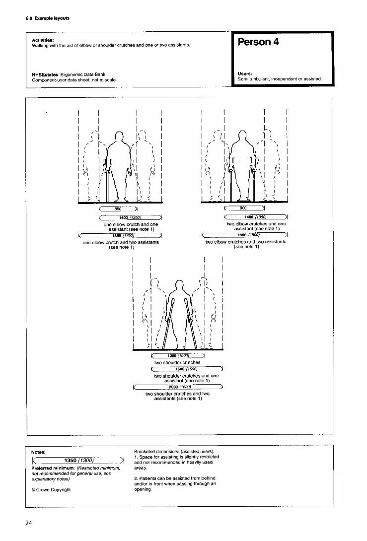
6.1 Ambulant people
The data sheets show space requirements for peoplewalking independently, with assistance and with walkingaids. The space requirements for people walking may be acritical factor in determining corridor width wherepedestrian traffic is particularly heavy, and especially inareas where people are frequently assisted and use walkingaids. Space requirements are given for various types ofwalking aids; generally it will be necessary to allow for useof the most space-consuming types-that is, walking-frames or shoulder crutches.


6.2 Wheelchairs
The ergonomic data sheets in this section relate to standard8L wheelchairs, which is one of the largest types most likelyto be used. (Where larger specialised wheelchairs are used,additional space may be required.) The skill of thewheelchair user is an important factor in determining spacerequirements, therefore the dimensions given take intoaccount the need to allow for the relatively high proportionof inexperienced wheelchair users who are likely to usehealth buildings.


6.3 Building approach
This set of ergonomic data sheets provides guidance for thedesign of various spaces and functional components whichconstitute the approach to the health building; theseelements fulfil a particularly important role in creating afavourable impression for visitors, most of whom will beunfamiliar with the site and many of whom normally findvisiting hospitals - in whatever capacity - a stressfulexperience.
A typical health building should ideally be on a level site,well lit (especially during non-daylight hours) and accessibleto all categories of user. In view of the physical limitations ofmany users, there should be few (if any) obstructions to freemovement to and through the building. On the buildingapproach, therefore, any street furniture should be offsetfrom the main pedestrian route; trees and shrubs should bepositioned so that they do not constitute a hazard, and allbranches should be kept trimmed. Specific guidance onsuch areas as car parks is given on the following pages.
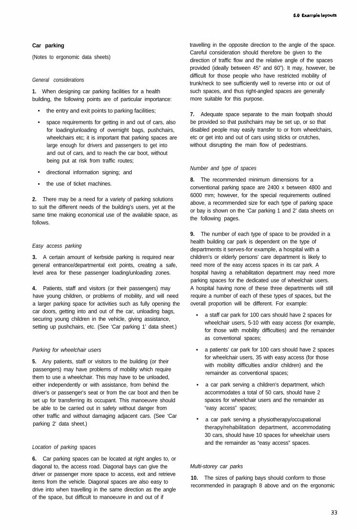
Car parking
(Notes to ergonomic data sheets)
General considerations
1. When designing car parking facilities for a healthbuilding, the following points are of particular importance:
• the entry and exit points to parking facilities;
• space requirements for getting in and out of cars, alsofor loading/unloading of overnight bags, pushchairs,wheelchairs etc; it is important that parking spaces arelarge enough for drivers and passengers to get intoand out of cars, and to reach the car boot, withoutbeing put at risk from traffic routes;
• directional information signing; and
• the use of ticket machines.
2. There may be a need for a variety of parking solutionsto suit the different needs of the building’s users, yet at thesame time making economical use of the available space, asfollows.
Easy access parking
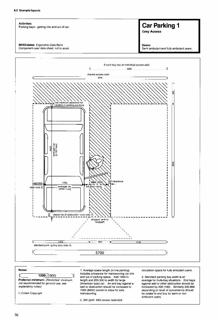
3. A certain amount of kerbside parking is required neargeneral entrance/departmental exit points, creating a safe,level area for these passenger loading/unloading zones.
4. Patients, staff and visitors (or their passengers) mayhave young children, or problems of mobility, and will needa larger parking space for activities such as fully opening thecar doors, getting into and out of the car, unloading bags,securing young children in the vehicle, giving assistance,setting up pushchairs, etc. (See ‘Car parking 1’ data sheet.)
Parking for wheelchair users
5. Any patients, staff or visitors to the building (or theirpassengers) may have problems of mobility which requirethem to use a wheelchair. This may have to be unloaded,either independently or with assistance, from behind thedriver’s or passenger’s seat or from the car boot and then beset up for transferring its occupant. This manoeuvre shouldbe able to be carried out in safety without danger fromother traffic and without damaging adjacent cars. (See ‘Carparking 2’ data sheet.)
Location of parking spaces
6. Car parking spaces can be located at right angles to, ordiagonal to, the access road. Diagonal bays can give thedriver or passenger more space to access, exit and retrieveitems from the vehicle. Diagonal spaces are also easy todrive into when travelling in the same direction as the angleof the space, but difficult to manoeuvre in and out of if
travelling in the opposite direction to the angle of the space.Careful consideration should therefore be given to thedirection of traffic flow and the relative angle of the spacesprovided (ideally between 45° and 60”). It may, however, bedifficult for those people who have restricted mobility oftrunk/neck to see sufficiently well to reverse into or out ofsuch spaces, and thus right-angled spaces are generallymore suitable for this purpose.
7. Adequate space separate to the main footpath shouldbe provided so that pushchairs may be set up, or so thatdisabled people may easily transfer to or from wheelchairs,etc or get into and out of cars using sticks or crutches,without disrupting the main flow of pedestrians.
Number and type of spaces
8. The recommended minimum dimensions for aconventional parking space are 2400 x between 4800 and6000 mm; however, for the special requirements outlinedabove, a recommended size for each type of parking spaceor bay is shown on the ‘Car parking 1 and 2’ data sheets onthe following pages.
9. The number of each type of space to be provided in ahealth building car park is dependent on the type ofdepartments it serves-for example, a hospital with achildren’s or elderly persons’ care department is likely toneed more of the easy access spaces in its car park. Ahospital having a rehabilitation department may need moreparking spaces for the dedicated use of wheelchair users.A hospital having none of these three departments will stillrequire a number of each of these types of spaces, but theoverall proportion will be different. For example:
• a staff car park for 100 cars should have 2 spaces forwheelchair users, 5-10 with easy access (for example,for those with mobility difficulties) and the remainderas conventional spaces;
• a patients’ car park for 100 cars should have 2 spacesfor wheelchair users, 35 with easy access (for thosewith mobility difficulties and/or children) and theremainder as conventional spaces;
• a car park serving a children’s department, whichaccommodates a total of 50 cars, should have 2spaces for wheelchair users and the remainder as“easy access” spaces;
• a car park serving a physiotherapy/occupationaltherapy/rehabilitation department, accommodating30 cars, should have 10 spaces for wheelchair usersand the remainder as “easy access” spaces.
Multi-storey car parks
10. The sizes of parking bays should conform to thoserecommended in paragraph 8 above and on the ergonomic

data sheets; the following additional factors should also betaken into account:
••
•
•
•
•
11.
the car park should be well lit, for safety;doors to lifts or stairways must be on the level, wide,and easy to open;
direction signs to stairs, lifts, exits and emergency exitsmust be easily located, visible and readable. Forfurther guidance, see paragraphs 20-22 below; alsothe relevant data sheets for external steps, lifts, doors,and signposting elsewhere in this volume; also the‘lifts’ data sheets in Volume 4 of this Note);
easy-access spaces and wheelchair users’ spacesshould be on the ground floor, and close to thepedestrian exit/s; if on all levels, they should belocated adjacent to the lifts;
if the different levels serve particular departments ofthe hospital, the bay sizes chosen should reflect this -that is, wheelchair users’ spaces should be closest toexits, the “easy access” spaces next closest, andconventional spaces in the remaining bays;
panic/alarm buttons should be provided at regularly-spaced intervals, and in prominent positions,throughout the car park.
When designing multi-storey car parks for healthbuildings, it is essential to avoid any routes to lifts/stairs viasteep ramps, or via steps or a platform at the door to the liftor stairway area, and to ensure that any such access routesavoid crossing traffic routes wherever possible.
Payment for parking
12. Ticket machines at barriers, and payment machines orkiosks at the entrance/exit of car parks can often causeproblems for short people and those with hand or armimpairments, as well as for those with hearing difficulties ifsound recordings are included in the device used.
13. It must be made clear whether Orange Badge holdersare exempt from payment of parking charges.
14. Parking meters:
• should be low enough for everyone to reach,including wheelchair users; people with handimpairments should be able to insert money with ease-in other words, the meters should be positioned at aheight of 900 mm-1200 mm from the ground, andaccessible from the parking bay or footpath;
• should be brightly coloured to contrast with theirsurroundings, to help partially-sighted people;
15.
•
•
•
Machines:
must have instructions which are easy to read andunderstandable, with controls which are easy tooperate;
should be at a height of 900 mm-1200 mm fromthe ground, with clear space for access in front;
should be provided close to the parking spacesallocated for disabled users (those who are notalready exempt from payment-see paragraph 13above).
Access route
16. The access route from the car park to the building orbuildings which it serves must be level or at a gentlegradient, preferably covered, and unobstructed, with aminimum clear width of between 1800 mm and 2000 mm.
17. Directional signs should be posted at all pedestrianexits to the car park. Colour-coding, or textured surfaces,should be provided for principal routes and also to informusers of changes in direction where appropriate.
18. If the footpath is raised from the car park, a droppedkerb should be provided at regular intervals throughout thecar park (see “dropped kerb” data sheet below).
19. Any wheelchair-accessible or “easy access” parkingspaces should be located close to the main circulation routeand car park entrance.
Signs
20. Directions to car parking areas should be signed fromthe main traffic routes; entrance and exit signs should beclearly visible from all parts of the car park.
21. At the entrance to the car park, the designated spacesfor different categories of user must be clearly signed ormarked. The international “access” symbol (in white on ablue background, 300 mm x 600 mm) should be used todenote spaces for wheelchair users. The signs for“accessible” spaces should be positioned both on theground and at a height (1500 mm from ground) where theycan be seen clearly, even when a car is parked in the space.
22. Signs should not be positioned where they mayobstruct an “accessible route” or cause a hazard to visually-impaired pedestrians.
• must not reduce the clear width of the accessibleroute to below the minimum requirement;
• should not cause an obstacle for pedestrians,especially those who are visually impaired.

Ground surface
23. The surface of the parking bays should be level, hard,and of a non-slip type. Uneven, loose gravel or stonysurfaces will make it difficult for people using sticks orcrutches, and extremely difficult for wheelchairs andpushchairs/prams, to manoeuvre. Steep cross-falls on pathsshould be avoided, as they may throw a wheelchair user, ora person’ walking on crutches, out of control.
Lighting
24. For safety and security, the lighting in outdoor carparks should be a minimum of 20 lux.
25. The lighting in covered car parks should:
• be a minimum of 20 Iux at floor level, 50 lux at rampsand corners, 100 lux at entrances and exits and 200Iux at kiosks and in ticket machine areas;
• be positioned to avoid glare to drivers andpedestrians;
• provide a transition zone, at entrances and exits, fromthe level of lighting inside the car park to the level oflighting outside, to accustom drivers’ eyes to thechange in level.


Dropped kerbs
(Notes to ergonomic data sheets)
General considerations
1. Reference should be made to Approved Document Mof The Building Regulations, also the Department ofTransport Mobility Unit’s advice note DU/1/91 (‘The use ofDropped Kerbs and Tactile Surfaces at Pedestrian CrossingPoints’).
2 . The design of dropped kerbs must take into accountthe different-and conflicting - needs of visually-impairedpeople and wheelchair users. Dropped kerbs make it mucheasier for wheelchair users, and people with pushchairs,trolleys etc., to overcome abrupt changes in level which theywould otherwise find difficult or impossible (for somewheelchair users, even a small jolt can cause acute pain).
3. Visually-impaired people, however, require somephysical indication of the edge of a pavement; in order toavoid walking unaware on to the road, kerbs are used bythem to indicate the presence of a road. If kerbs areremoved to aid people with mobility difficulties, a substituteindicator of the road’s presence must be provided -that is,if the pavement is level with the road, there should be achange in texture (distinguishable through the soles ofshoes, and by the canes used by visually-impaired people)provided as a warning indicator; adequate drainage mustalso be provided.
Location
4. Dropped kerbs must:
•
•
•
be provided at locations where people leave thepavement to cross the road, at which points theremust be an unobstructed view of traffic approachingfrom any direction;
always be directly opposite one another across a road.It is dangerous to have one on only one side of theroad, as a person may be unable to mount theopposite kerb and then be stranded in the flow oftraffic;
be provided at any vertical rise greater than 13 mm.
5. Dropped kerbs should be avoided at places wheredoors occur. Doors should not have to be opened at thesame time as negotiating a kerb ramp, as this is extremelydifficult for wheelchair users and people with pushchairs-awheelchair user, after mounting the kerb ramp, will be tiltedbackwards, and is therefore unlikely to be able to reach thedoor handle, whereas people with pushchairs will not beable to reach the handle without walking around thepushchair, and will then need to pull the pushchair throughthe door.
Gradient
6. The gradient of the dropped kerbs must allow people tonegotiate them easily and quickly move out of the flow of
traffic. Steep dropped kerbs may cause people to losecontrol of wheelchairs and pushchairs.
7. The gentler the slope, the more people will be able touse it with ease and safety. The pavement must be dishedover the area of the dropped kerb, with no abrupt changeof slope and a maximum gradient of 1 : 12.
8. Dropped kerbs with returned sides are only acceptablewhere they do not interfere with the main direction ofpedestrian flow and where people are not required to walkacross them.
Width
9 . Dropped kerbs must be wide enough for doublepushchairs and electric pavement vehicles to negotiatethem. The flush width should normally be a minimum of2000 mm. (In locations of high flow, the flush width shouldbe 3000 mm.) The minimum width can be reduced to 1200mm adjacent to areas of car parking reserved for disabledusers.
Depth
10. At a 2000 mm-wide pavement, dropped kerbs shouldextend over the entire depth. Where the pavement is 3000mm wide or greater, a level area 1000 mm wide can beprovided behind the dropped kerb.
Surface
11. The dropped kerb should have a tactile, modifiedblister surface covering the dropped kerb area inaccordance with DU1/91,‘The Use of Dropped Kerbs andTactile Surfaces at Pedestrian Crossing Points’, to indicate itsexistence. Textured surfaces help ambulant disabled peopleto keep a firm grip, as well as indicating to visually-impairedpeople the change in level.
12. The bottom of a dropped kerb should be rounded, orotherwise distinguishable - for example, by a tactile strip -to help visually-impaired people locate them. A continuousyellow line should be painted along the edge of the roadclosest to the kerb.
13. The following types of dropped kerb should beavoided: those with non-parallel sides; with a camber; ontoroads with a steep camber or concave gutter; projectinginto the gutter; sited near drains; or those located close toloose surfaces such as gravel or earth (as these may get ontothe ramp and affect the surface performance).
14. Where gratings are installed for the purpose ofconducting rain water away, these should be locatedupstream of the kerb ramp, in order to prevent flooding atthe bottom of the ramp. Where gratings occur in front ofkerb ramps, the holes should be small to prevent wheelchaircastors and walking aids becoming stuck; to achieve this, theslots should not be more than 12 mm wide, with metal atleast 13 mm thick, and aligned at 90° to the direction oftravel. All grating surfaces should be set level with theroadway; it is best that gratings are not located at crossings.


Ramps
(Notes to ergonomic data sheets)
General considerations
1. Reference should be made to Approved Document Mof The Building Regulations for specific legislativerequirements.
2. Ramps enable people with wheelchairs and pushchairsto move easily between one level and another, and shouldbe provided where any changes in level occur. However, forambulant disabled people, a ramp is not as convenient, easyor safe to use as steps, and therefore a ramp should alwaysbe accompanied by steps.
Gradient
3. Ramps must be of a gradual gradient, in order thatwheelchair users can negotiate them independently (mostcan manage a slope of 1 : 15 or 1:20). The followinggradients are recommended:
• 1:10 for short ramps less than 3000 mm (steepergradients are more practical for very short distances);
• 1:12 for distances up to 5000 mm (and for distancesup to 5000 mm between landings);
• 1: 5 for distances up to 10000 mm (and for distancesup to 10000 mm between landings).
Width
4. The preferred width for a ramp is 1500 mm (a minimumwidth of 1200 mm, with an unobstructed width of1000 mm). A width of 1800 mm will allow two wheelchairusers to pass. (Reference should be made to the ‘person’and ‘wheelchair’ ergonomic data sheets in this Volume forfurther information on space requirements for users andtheir assistants.)
Length
5. The length of a ramp is dependant on the gradient andthe change in height to be overcome, but should neverexceed 24000 mm, and in any case should not exceed10000 mm without a rest landing.
Approach space and landings
6. Level approach spaces (clear of any door swing orobstruction) should be provided at the top and bottom ofany ramp. Areas measuring 1500 mm x 1500 mm arepreferred (minimum 1200 mm x 1200 mm), and anyintermediate landings should be not less than 1500mm inlength.
7. Landings should be provided at any changes indirection of the ramp which are greater than 10°, and atintervals of 10000 mm where appropriate.
8. Tactile cues should be provided, including foot-detectable changes in surface 450 mm long across thelanding at both ends of the ramp. Such changes couldsimply be from a carpeted surface to a vinyl surface;corduroy or blister tactile surfaces should not be used in thisinstance.
Handrails
9. It is important that ramps have handrails, which givevital support, confidence and security to all users byproviding lateral body support and hand support as well asproviding tactile cues for visually-impaired people. Handrailsmay also provide support for independent wheelchair userswhen resting on the ramp.
10. Handrails are required on both sides of a ramp toassist people with disabilities on their right or left, as well asthose carrying bags in one hand. Handrails should beprovided on any ramp with a rise greater than 150 mm.
11. It is recommended that handrails are provided at twoheights-a standard one 900 mm above the ramp surface,and a lower one 610 mm above the ramp surface forchildren and wheelchair users.
12. Handrails must be continuous around dog-legs orswitchbacks and over landings; where this is not possible,they should extend horizontally a minimum of 300 mmbeyond each end of the ramp before being returned to thewall, floor or post, in order to allow users to regain theirbalance on the level area.
13. These extensions also indicate the presence of a rampfor visually-impaired users, but they should not project outinto the path of other pedestrians.
14. Further detailed guidance is given in the Notes to the‘handrails’ ergonomic data sheets later in this volume.
Edge protection
15. The open side of a ramp or landing should have araised kerb in order to prevent feet and wheels slipping off.The kerb or barrier should be painted in a contrasting colourto the ramp and its surroundings.
Surface/appearance
16. There should be contrasts of colour and tone betweenthe ramp and adjacent areas, such as handrails andbackground colour. If coloured markings are to be providedon the ramp itself, however, they should form a ‘Vconfiguration pointing in the change of direction, ratherthan a line at top and bottom which could create confusionwith stairs.
17. Ramps should have a permanent, regular, non-slipsurface. Indoor ramps should not be covered in deep-or shag-pile carpet, as this is difficult to traverse in awheelchair. External ramps should not be covered withglazed or polished masonry or cobblestones.

18. Outdoor ramps should not allow the accumulation ofwater on their surface; for this reason, a camber of 1:100(max. 1:50) is permissible, which should not affect thesteering of wheeled conveyances or other items. Thereshould be gaps of 10-15 mm left at intervals in the edging,above the level of the ramp, to enable rainwater and grit todrain off.
19. Ramps can be dangerous in wet or icy weather. Wherepossible, outdoor ramps should have a canopy above, toprotect them from rain and snow.
Obstructions
20. Where a ramp leads down to a road or any placewhere there may be traffic, a barrier in the form of a railingto a height of 1100 mm across the full width of the rampshould be installed at the bottom of the ramp, in order toprevent users walking or rolling into the road; such a barriershould be no more than 1500 mm from the base of theramp.
21. Where a ramp intersects with a pedestrian route,there should be a level area of 900 mm length, in order toallow wheelchair users and people with pushchairs to turnround and join the flow of pedestrians.
22. The ramp should be clear of obstructions for the widthof the ramp and to a minimum height of 1980 mm(excluding handrails).
Lighting
23. External ramps and walkways should have a minimumlighting level of 75 Iux at the pavement. This should beincreased to 150 Iux where the building is designedspecifically for visually-impaired people.


Externalsteps
(Notes to ergonomic data sheets)
General considerations
1 . Reference should be made to Approved Document Mof the Building Regulations for specific legislativerequirements.
2. If a level approach to the building’s entrance cannot beachieved, then steps and a ramp must be provided. Stepsare preferred to ramps by many people, and, when correctlydetailed, steps provide independent access for manyambulant disabled people-for example, those with arthritisor those who use crutches. However, steps are a barrier topeople in wheelchairs or with pushchairs/prams etc., so aramp should be provided wherever there are steps (seenotes to data sheet ‘ramps’ above).
Approach and landings
3. People with impaired sight are at risk of tripping orlosing their balance when meeting sudden changes in level;this risk is at its greatest when approaching the head of aflight of steps. The existence of steps, on their own or withina flight, should be made apparent; stairs should be designedso that they are not a continuation of the line of normalpedestrian travel.
4. The clear, unobstructed length of landings should be1500 mm (1200 mm as a minimum). The top and bottomsteps of a flight should not encroach onto the landing area.
5. Steps should not interfere with circulation spaces; theyshould be recessed from the circulation route by at least600 mm at the top and 750 mm at the bottom, to avoidpedestrian collisions and to allow handrails to level out.
Height
6. Although many ambulant disabled people find it easierto climb steps than to use ramps, it is still important that anyflights of steps are not too long and are broken up bylandings. The maximum permitted height for the rise of aflight of external steps between landings is 1200 mm, and itis recommended that there is a minimum of three and amaximum of nine steps.
7. Generally, the flatter the pitch (angle), the safer stepswill be. The recommended pitch for public steps is 27° (witha maximum of 38°).
Risers and goings
8. Risers and goings should be uniform throughout theflight, as any irregularities can cause people to stumble.
Nosings
9. Nosings should be marked in a colour/tone thatcontrasts with the colour of the stairs, extending the fullwidth of the step and reaching a depth of 50-60 mm onboth tread and riser. Any edges should be firmly fixed andbe of a non-slip type. Sharp nosings and abrupt anglesshould be avoided.
Edge protection
10. It is necessary to prevent feet, crutches and sticks fromaccidentally slipping off the edge of open-plan steps. Forsteps not adjacent to walls, a barrier, with a maximumheight of 100 mm above the level of the treads, should beprovided.
Step surface and type
11. The surface of the steps must be (and also appear tobe) non-slip, and to aid visually-impaired people the risersshould be a contrasting colour to the treads. A fall of 1:100 is recommended, to prevent water from accumulating onthe steps and to maintain a non-slip surface in wetconditions.
12. A change in surface texture at the top and bottom ofeach flight of steps is needed, to act as a warning forvisually-impaired people that there is a change in levelahead. This surface should be of a corduroy texture.
Width of steps
13. Distractions should be avoided, especially at the top ofsteps where people may lose their concentration as well astheir footing.
14. In addition, the use of open risers is notrecommended, since they are especially dangerous for theambulant disabled - such as those users with braces andprostheses-who need a solid riser to guide their feet ontothe next tread. Open risers allow feet to catch on theunderside of the tread, and are therefore also hazardous tothose using sticks and canes.
15. Single steps, and any changes in level of less than100 mm, are to be avoided, as are spiral and helical steps.
16. The steps must be wide enough for people tonegotiate comfortably by holding onto either one or bothhandrails or by being assisted. The width of the steps shouldreflect the amount of pedestrian traffic (reference should bemade to the ‘person’ ergonomic data sheets in this volumefor further information on space requirements for users andtheir assistants).
17. A minimum clear step width of 1000 mm for oneperson, or 1500 mm for two-way traffic, is necessary. Amiddle handrail should be provided on any flights of stepswider than 1800 mm.
Previous pageis blank


Handrails
18. Reference should be made to the ‘handrail’ data sheetlater in this volume for further guidance.
19. Handrails are required by some users to help them topull up steps; they are also used for balance and supportwhen descending. Handrail extensions also provide tactilecues to the presence of changes in level for visually-impairedpeople.
20.
•
•
•
Handrails:
must continue for a minimum of 300 mm horizontallyfrom the top step; where the handrail does notinterrupt pedestrian routes, an extension of 450 mmfrom the top step is recommended. Central handrailsmay project into the landing by the same amount asthe going, and for external steps leading to anentrance door the central handrail should continueacross the landing to the door;
must be located within the width of the tread; and
should be provided on both sides of the steps, toassist people with left or right disabilities, those usinga walking stick, or those carrying a bag in one hand.
Balustrades
21. Balustrades should be provided around landings to aheight of 1100 mm, to prevent people falling. They shouldnot allow young children to fall between the gaps (whichshould be no wider than 100 mm), nor provide toeholds forclimbing up.
Lighting
22. Steps and landings should be well illuminated, eithernaturally or by artificial means. The lighting should bedesigned so that it highlights the differences between risersand treads, the top and bottom steps, and any changes indirection.

6.4 Doors and lobbies
Doors
(Notes to ergonomic data sheets)
General
1. Guidance on the use of doors and doorsets in healthbuildings is contained in HTM 58 ‘Internal doorsets’.
2. Doors in health buildings will be used frequently bypeople in pain or with reduced strength, those with reducedhand function or reduced mobility, or those in wheelchairs.People may also be carrying children, overnight bags orhospital equipment, or manoeuvring other equipment suchas trolleys, or pushing pushchairs or wheelchairs-all ofwhich make it difficulat to push or pull doors open.
3. Bomber hinges should never be used, as these cancause doors to swing back and injure an unsuspectingvisually-impaired person or a person with mobilitydifficulties.
Approach
4. Reference should be made to the ‘Lobby’ and ‘Corridor’data sheets elsewhere in this volume.
5. A level area is required in front of doors to allow peopleto stand or park a wheelchair or pushchair whilstmanoeuvring the door. The surface of the floor or groundmust be non-slip.
6. It is advisable that doors open away from areas with ahigh pedestrian traffic flow, towards areas with a lowerpedestrian traffic flow. There must be sufficient space toone side or both sides of a door to allow for people to passor wait for others coming through in the opposite direction.Where there is high usage it will be necessary to provide awaiting space on both sides of the door.
7. Doors at the corners of rooms should be hung with thehinges nearest to the corner so that the door rests alongsidethe wall when open. This allows the maximum access spaceat the side for people with wheelchairs or pushchairs, orpeople with other mobility difficulties, to manoeuvreeffectively and pass through the door. A minimum of300 mm must be provided on the handle side of the door,to allow space for approaching and opening the door.
8. Doors should not open outwards into restrictedpassageways (for example, corridors and smaller circulationareas), except in instances such as rooms with (necessarily)more restricted dimensions (toilets, walk-in cupboards,etc.). The use of outward-opening doors for toilets isimportant, in that assistance can be given in the event thatthe occupant falls against the door.
Thresholds
9. A step and thresholds must be avoided whereverpossible, or, where this is unavoidable, kept to a minimum.It is impossible for wheelchair users, or people withpushchairs and trolleys, to negotiate a door and a thresholdat the same time. (See also ‘Dropped kerbs' data sheetearlier in this volume.)
10. It is possible to use recessed drainage channels orother alternatives to divert water away from doors, and touse draught excluders instead of thresholds. Where athreshold is unavoidable, its maximum height should bebetween 10 mm and 13 mm; rubber thresholds are themost easily traversed by wheelchairs and pushchairs.
Door width
11. A minimum width of 900 mm for a single-leaf doorsetis recommended. In areas of heavy use, a minimum width of1000 mm is preferred, in order to to allow the free passageof wheelchairs and double pushchairs.
12. Table 1 on the data sheet ‘Doors 1' gives therecommended effective limits for door width.
13. For double-leaf doors, both leaves should eitheropen in the same direction or swing both ways. Therecommended width of a double doorset is 1800 mm,comprising two 900 mm-wide doors. Alternatively, theminimum width is 1550 mm, divided asymmetrically withthe smaller of the two doors a minimum of 750 mm. Toavoid confusion, wherever an asymmetrical doorarrangement occurs, this provision should be consistentthroughout the building.
Force to open door
14. The force required to push or pull doors shouldgenerally be kept to a minimum, to allow everyone -including children, elderly and frail people-to open themeasily. Fire doors, however, should be capable of beingopened by exerting the minimum force as stipulated inBS5588.
Door closers
15. Door closers or rising-butt hinges should be fitted toevery door, to prevent doors being left half-open, whichwould render visually-impaired people at risk of injury.Rising-butt hinges and horizontal-bar handles can be usedas alternatives to automatic closers on those doors whichare required to be kept shut.
16. Automatic closers must allow sufficient time forpeople to pass through the door (the door should remainfully open wide for at least 6-7 seconds). As the door closesit is recommended that there is a 3-second minimum delayfor the door to move from 90° to 12°, to prevent injury toany persons standing close by. Automatic closers must have

a check mechanism, to prevent them swinging beyond theclosed position. Doors fitted with closers should provide amaximum resistance of 35 N (external doors) or 25 N(internal doors).
17. Fire doors fitted with automatic closers are heavy andawkward to open, thus forming a major barrier to easycirculation for many people. It is recommended that firedoors on circulation routes be fitted with electromagneticstays, which in the event of a fire will break the circuit andcause the doors to close. On doors which are designed toremain open, the edges should be recessed when open inorder to avoid creating an obstruction; alternatively, theedges could be highlighted to make them more obvious andnoticeable.
18. Strong floor spring closers (often fitted to externalheavy doors) should be avoided, unless used in conjunctionwith automatic opening and closing devices.
Door handles
19. Door handles should be easy to use by people withweak hands and arms, also people using walking frames orcrutches or carrying objects, etc. Door handles should allowa firm grip for the hand, and be fixed at the correct heightand positioned at a consistent height on all doorsthroughout a building. Consistent positioning allows people-particularly those who are visually-impaired-to anticipatethe handle position and thus find the handle more easily.
20. The colour of door handles should be contrasted tothat of the door, so that the handles are easily identifed byvisually-impaired people.
Pull handles
21. Knobs and round pull-handles should be avoided,since people with impaired hand function find these difficult(if not impossible) to use.
22. Vertical pull-handles enable people of differentheights, or those, sitting in wheelchairs, to grasp them at aheight which gives them the best mechanical advantage,enabling doors to be opened more easily. To facilitate this,the pull-handles should have a minimum length of 300 mm.
23. Handles used for pushing or pulling should be fittedon both faces of the door. Doors should be clearly markedwith a sign adjacent to the handle to indicate whether thehandle should be pulled or pushed. Handles should beD-shaped, to reduce the risk of catching clothing or causinginjury.
24. Horizontal-bar handles across the width of the doorcan be fitted in addition to vertical handles for ease ofopening and closing. Horizontal bars provide support topeople with mobility difficulties who may be unsteady; thebars help them to keep their balance as they pass throughthe door. It is desirable that any doors which are not fitted
with automatic closers should be fitted, along the full widthof the closing side of the doors, with horizontal pull-bars,mounted at a maximum height of 1000 mm.
25. It must be noted, however, that horizontal bars reducethe clear opening width of the door, and this must beconsidered when selecting the doorset.
Handles for latching doors
26. Door handles which unlatch must be easy to graspand open with one hand and not require tight grasping,pinch grips, extensive twisting of the wrist, or fine finger-control to operate them. Lever handles are recommended,because they can be operated using elbows if a personsuffers from impaired hand function. Handle design shouldminimise the risk of catching clothing or causing injury-forexample, by curving the end of the lever towards the door.
27. Minimal force should be required to operate the doorhandle.
Sliding doors
28. Sliding doors are economical in space, and automaticsliding doors are easiest to use by everyone. Manually-operated sliding doors should be avoided, since they aredifficult to operate by most people-indeed, oftenimpossible for elderly people and those with mobilitydifficulties or impaired hand function. Where manually-operated sliding doors are unavoidable, the door handlesshould be mounted vertically, easy to grip and not recessed.
29. Sliding doors should:
• be clearly marked as such, to avoid confusion withconventional push/pull side-hung doors;
• be well-maintained, to ensure that the tracks allowsmooth movement;
• incorporate a safety device (that is, a guard), eitheralong the length of the sliding sections or betweenthe doors and walls.
30. Heavy sliding doors may be fitted with a cord andgeared pulley mechanism to ease the opening and closingprocedure. Other possible solutions are a counterweight toclose the door or an inclined track to carry the door;however, both of these solutions would increase thedifficulty of opening the door.
Automatic doors
31. The provision of automatic doors is generallyrecommended, as automatic doors require no effort by theuser; this type of door arrangement is especially desirable inareas of high use (that is, the main entrance to a healthbuilding).

32. Automatic double sliding doors should have a1200 mm clear width, with a 1200 mm clear approachspace in front of and behind them.
33. Automatic doors can be triggered by a photo-electriclight barrier, pressure pads or selector switches. The sensorsoperating automatic doors must acknowledge children,wheelchair users and guide dogs as well as taller people,and the sensor should not allow the door to close if thedoorway is not clear. If floor sensors are used they should besensitive to uneven pressure-for example, that exerted bypeople using crutches. Push buttons to activate automaticdoors should be sited out of the door swing, at a height of1000 mm and should measure approximately 50 mm by
Kick plates
39. Doors should be fitted with kick plates, which shouldbe mounted to a minimum height of 400 mm on the pushside of doors to protect them from damage from pushchairsand wheelchairs.
Contrast
40. Door frames should be a contrasting colour to thewalls or surroundings, and door handles should be acontrasting colour to the door itself, to enable visually-impaired users to locate them easily.
Information50 mm. 41. All name, number and information plates on or
34. Automatic sliding doors are preferable to automaticswing doors, as the latter could cause injury if other peoplenear to the door have insufficient time to move out of theway.
adjacent to doors must be at a height of between 800 mmand 1500 mm above floor level, so that they are easilyreadable (either by sight or touch). (For specific guidance,see the notes to the 'Signposting' data sheets elsewhere inthis volume.)
35. Automatic doors which swing towards the user arepotentially dangerous, and should only be used when theyform part of one-way routes where they can swing awayfrom users. Where doors unavoidably swing into thedirection of travel, there should be guard-rails erected atright angles to the wall housing the door, which are at aheight detectable by the canes used by visually-impairedpeople. Where the floor surface allows, it is desirable thatthe area which each door swings through should be markedon the floor by contrasting coloured lines or hatching. Inaddition to the swing space, for swing doors, there must beat least 1400 mm of clear space in front of the door, whichshould be clearly marked on the floor.
36. The use of revolving doors should be avoided, as theyare very difficult (if not impossible) to negotiate for thosepushing pushchairs or using wheelchairs. Similarly, doorsthat swing towards each other into the intervening spaceare not recommended.
Glazing
37. All door glazing should be easily identifiable as such,and frameless glass doors should be easily recognisable inorder to prevent people colliding with them, and also to aidvisually-impaired users-that is, by the use of smoked glasstogether with coloured signs at eye level, or coloured, full-width horizontal door handles.
38. Doors which swing in both directions, and also one-way doors in corridors etc., should contain a glazed portionto allow people to see others approaching from theopposite direction.


Lobbies
(Notes to ergonomic data sheets)
General considerations
1. Reference should be made to Approved Document Mof the Building Regulations for specific legislativerequirements.
2. Lobbies are generally provided at entrances todepartments, and should also be provided in situationswhere a toilet opens off a corridor.
3. In reception areas the doors should be visible from thereception desk, to enable assistance to be given to anyonehaving difficulty in negotiating the entrance. The doors canbe parallel to each other, or at right angles.
Approach
4. The two sets of doors should preferably swing in thesame direction or in both directions. Doors can swingtowards each other in wider lobbies, or where the doors areoffset. For automatic doors, both inside and outside thebuilding, the zones for the open doors should be guarded toafford protection for the users.
5. For further information, see the ‘Doors’ and ‘Corridors’data sheets elsewhere in this volume.
Length
6. There must be sufficient space for a person with apushchair, trolley or wheelchair, and someone passing inthe opposite direction, to pass through and close one doorbefore opening the next. For automatic doors, the lobbylength should allow for one set of doors to close before theother set opens when a person passes through at normalwalking speed. However, the mechanism should not be setso that the second set will not open until the first has closed,since in an emergency, where speed of passage isimportant, such an arrangement could cause a delay andgive rise to accidents.
Lobby width
7. The purpose for which the space is used may influencethe size of the lobby doors or the decision to provide doublerather than single sets of doors. Most wheelchairs can passthrough a 900 mm doorset, but double pushchairs require a1000 mm doorset. Wider doors are preferable to doubledoors, since it is difficult to hold open two doors at the sametime as pushing a pushchair or propelling a wheelchair.
8. The lobby must be wide enough to allow the passage ofdouble pushchairs, people using crutches and other walkingaids, and also guide dogs, wheelchairs and trolleys orequipment if required.
Space at side of doors
9. For single-leaf doors there should be a space providedat the latch side of each door to allow people access to thedoor handle and to allow them to pass in oppositedirections. The recommended space is:
• 600 mm (450 mm) to the latch side of the door, whenthe door opens towards a person;
• 450 mm (300 mm) to the latch side of the door, whenit swings away from the person;
• 600 mm on both sides of the door, where doorsswing in both directions.
Surface
10. Lobby surfaces should be level, and there should be nothresholds.
11. Mats should be of firm tread, to offer resistance to thewheels of wheelchairs (in order to keep the wheelchairstationary while the user opens the door); these mats shouldbe close-fitting, flush with the floor surface withoutprotruding trim, and, if of the linked type, they must nothave openings greater than 18 mm in diameter, which maycatch the foot of walking sticks etc. Soft coconut mattingshould not be used, as this is difficult to traverse withwheelchairs or pushchairs.
Lighting
12. The lighting of entrance lobbies or their equivalentareas should be varied, in order to make a gradual transitionbetween a bright outdoor environment and a moresubdued interior. The recommended level for lighting inlobbies is 200 lux.


6.5 Circulation and orientation
Signposting
(Notes to ergonomic data sheets)
General considerations
1. Reference should be made to HTM 65, ‘Health signs’.
2. Signs are of three main types:
l informational -showing the availability of a facility/service;
l directional -generally in the form of an arrowpointing towards the facility/service;
l locational -the provision of an identifying sign at theactual site of the facility/service.
3. People using health buildings may be easilydisorientated due to illness and/or upset; they may be inunfamiliar surroundings; they may have difficulties withsight, hearing, mobility or learning, or they may not haveEnglish as their first language; or they may need informationto be presented at a lower level because they are in awheelchair. If due consideration is given, at the designstage, to the information content, layout, presentation andlocation of signs and the provision of auditory information,these elements can all enable people to feel more confidentand less anxious when using a health building.
4. Signs are an integral part of enhancing the accessibilityand the usability of the buildings and their environment,and should be used effectively and sparingly to identifycirculation directions, rooms, spaces, amenities, accessibleentrances, emergency information, and also to indicatewhere help may be available, etc. Any signs used shouldfollow the RNIB/GDBA Joint Mobility Unit guidelines.
Signs for people with special needs
Visually-impaired people
5. Factors such as the location of signs, size and type ofcharacters, colour/tone contrast of text with backgroundand background with wall surface, the use of tactileembossed lettering and general good standards and levelsof lighting, will all enable visually-impaired people to findtheir way independently. Clear, audible information canalso be a help. Although few visually-impaired people readBraille, this could be utilised in some areas where there areknown to be more Braille users.
6. In areas where assistance is provided for visually-impaired people, the relevant internationally recognisedsymbol should be incorporated into the signage for thoseareas.
Hearing-impaired people
7. Hearing-impaired people rely heavily on visual
information. They may find it difficult to register the contentof spoken information, especially against a noisybackground; in this context, the use of such aids asinductive loops may need to be considered.
8. Many hearing-impaired people, particularly the elderly,will also have a sight impairment. Many of the featureswhich enable visually-impaired people to find their way willalso therefore aid hearing-impaired people. Again,wherever specific assistance is provided for hearing-impaired people, the relevant internationally recognisedsymbol should be used on any signage.
People using wheelchairs for mobility
9. Because those sitting in a wheelchair have a lower lineof sight than those standing, wheelchair users may beunable to see a sign positioned high on a wall; signs shouldtherefore be placed at a sufficiently low level, and spacemay also be required in front of the sign so that people canpark the wheelchair to read it.
10. Wherever facilities are provided for people inwheelchairs, the internationally recognised access symbolshould be used. This symbol:
l should show the wheelchair facing to the right exceptwhen the direction signs point to the left.
l must only be used where facilities in buildings are fullyaccessible to disabled people; any buildings whichincorporate only some “accessible” facilities shoulduse the symbol in conjunction with words orpictograms to denote the extent of accessibility.
11. Any signs intended for use by those in wheelchairsshould indicate the most convenient way for them to reachthe facility concerned.
People with learning difficulties
12. People with learning difficulties may find it difficult toperceive, comprehend or interpret the informationpresented on signs; they have difficulty with orientation,and in some cases lack the ability to distinguish colours ordifferentiate left from right. Health buildings shouldtherefore be designed with layouts which are simple anduniform, in order to be easily understood and assimilated bythose who have restricted orientation capabilities.
People with linguistic difficulties
13. The specific needs of people with linguistic difficulties- for example, those whose first language is not English, orthose who are illiterate - need to be considered in designingsigns for health buildings. In some localities, bilingual signsmay be required.
Route finding
14. A variety of methods to assist orientation and generalroute-finding can be used, to cater for people with different

levels and categories of ability; these methods includetextured or coloured floor surfaces, tactile embossed plans,and coloured guiding lines on walls or floors. Theeffectiveness of such methods will largely be dependent onthe way in which they are used to facilitate the location ofsuch amenities as toilets, lifts, telephones.
mounted permanently on the stairway side of the wall, onthe latch side of the doors leading to exit stairways.
22. Signs should not be placed behind glass, as this cancause reflections (as well as problems of readability shouldthe glass become defaced or smashed).
Location of signs 23. Signs should not project from the wall or hang from
15. Many people with disabilities have a restrictedcapability in their head and neck movements, which reducestheir peripheral view. Signs must therefore be placed withinthe angle of normal sight (i.e., 30° from the centreline of theface from which a person can see to either side), taking intoconsideration the most appropriate viewing distance anddirection. Where possible, signs must be positioned on wallsto avoid creating hazards or obstacles. Any signposts mustnot obstruct otherwise accessible routes. (See ‘Signposting3’ data sheet.)
the ceiling, since any such signs would need to be abovehead height, with a minimum clearance which is compatiblewith an easy reading height.
24. Signs should not be located on inwardly-openingdoors off corridors, since they are difficult to view becausethe face of the door is recessed from the wall.
Height and size of signs
25. Wall-mounted signs, including tactile ones, must belocated between 1400 mm and 1600 mm from the floor,where they will be in constant view and not obstructed. Thisheight allows both seated and standing persons to readthem, if the letters are tactile embossed. The minimumheight of the base of signs above the floor should be750 mm. The top of signs should be at a maximum heightof 2600 mm from the floor, and for any unavoidablesuspended or protruding signs there must be headroomclearance of 2300 mm. Wall-mounted signs should havetheir centreline at a height of 1500 ± 25 mm from the floor.
16. Special attention should be paid to concealed barriersin circulation routes - for example, ramps or steps. Priorwarning should be given, to allow disabled persons toassess the barrier and their capability of traversing it. It isalso recommended that any ramps which are concealedfrom view are signposted, giving details of their gradient -and, if steeper than 1:20, also giving their length.
17. Signs should be located so that they are easily noticedand read by all. Some people will need to get close to a signto read it, thus the approach space should be clear andunobstructed.
18. Directory boards should be located at all entrances tothe building and on each level, showing directions toimportant facilities within the building such as the receptionarea, lifts, toilets, fire escapes, etc.
19. Special attention should be paid to signage for fireescapes and emergency assembly points, especially in multi-storey buildings. Fire exit doors are often sited away fromthe main circulation route, so it is important to provideadequate signage to these doors for the benefit of thoseunfamiliar with the building.
20. Signs should be positioned so that they form a logicalsequence from the point of departure to the point ofdestination. They must be consistent in the terms anddescriptions used throughout a route, and should berepeated at any changes of direction, intersections of routesor where changes in level occur.
21. Signs denoting parts of the building, rooms, etcshould ideally not be located on the door to the areaconcerned, but rather at the side of any doors, pairs ofdoors or openings and within 150 mm of the door jamb.Signs should only be placed on doors where these haveautomatic closers and are unlikely to be propped open. Instairway areas, signs denoting floor level should be
26. The recommended height range for viewing from astanding position at a distance of 4-6 m is 1200- 1700 mm,with important signs at the optimum height of 1500 mm. Itmay be necessary to have larger signs at a higher level inareas where there is heavy pedestrian traffic and wherethere is a risk of visual obstructions.
27. The size of signs is important: a sign which is too smallfor its purpose may go unnoticed. Letters, numerals,symbols and pictographs should be large enough to be readeasily from an appropriate distance-for example, symbolson lavatory doors in a corridor are likely to be read from ashort distance, dependent on the width of the corridor, but“access” symbols in car parks denoting reserved placesmust be readable from a distance of several metres.
28. The characters used on signs should be of a plain fonttype -for example, not italic or highly stylised. A letterheight of 15 mm minimum and 51 mm maximum, raised1 mm and well spaced to allow individual letterdiscrimination, is recommended for the benefit of visually-impaired people. For a sign viewed at 3 m, the minimumrecommended text size is 100 mm and the maximum170 mm.
29. Symbol size will depend on the size of the sign, itslocation and purpose, also on how much text must beincluded in the sign. The sign must be legible and

recognisable. The following symbol sizes for differentviewing distances are recommended:
Viewing distance (m)
0-77-1818+
Minimum size (mm)
60 x 60110 x 110200 x 200max. 450 x 450
30. Further guidance regarding recommended charactersizes for different types of sign, including details of variousmandatory requirements, is contained in HTM 65, ‘Healthsigns’.
Information design
31. Signs should present positive (not negative)information.
37. Simplified, tactile embossed plans should be madeavailable to allow blind people and partially-sighted peopleto perceive their route by touch.
Lighting
38. Spaces should be well lit but not too bright so that thesigns, coloured floor and wall surfaces, and the faces ofpeople who give information, etc, can be seen easily. Thecolour of the lighting should not affect the colour of thesigns. Careful consideration should be given to the positionof items such as direction boards in lobbies, etc., which mayoften receive (unwanted) light or reflection from windows.
39. The position of the lighting must take intoconsideration the most frequent angle of view, and also anysurrounding objects. The light falling on signs should notproduce reflections or shadows, which would make themdifficult to read. Additionally, signs should have a glare-freesurface.
32. Signs should avoid the use of abbreviated wordswhere possible. Short words should be used in preferenceto long words where meanings are equivalent. Words areeasier to read if uppercase letters are only used for the firstletter of a sentence and proper nouns, and lowercase for allother letters.
Audible information
40. Audible information (for example, where patients in awaiting area need to be called for appointment) must beclearly audible above ambient background noise.
33. The colour of signs should also be consistent, andmaintained throughout a building; characters, text andsymbols on signs must contrast in colour and tone with theirbackground, and the background should in turn contrast incolour and tone with the surface to which the sign is fixed.Note, however, that use of red and green together, or blueand yellow together, must be avoided as these are difficultto distinguish for people who are colour-blind.
41. Inductive loops and infra-red systems should beconsidered when providing facilities for hearing-impairedpeople. Receivers can be compatible with the T-switches onhearing aids.
34. Notice should also be taken of the mandatory use ofcertain colours and tones to denote such conditions assafety, prohibition, warning - see HTM 65 for specificguidance.
Tactile properties
35. Characters and symbols on doors and identifyingspaces and directions in buildings should be raised so theymay be distinguished by touch by the visually impaired.Engraved text, unless coloured, should be avoided, as theindents may fill with dirt or cleaning fluids etc and preventtheir intended use. In addition, it must be remembered thatengraved text cannot be touch-read by visually-impairedpeople.
36. If Braille is used, the Braille characters should be sitedto the left of standard characters to make them convenientto read. Standard dot sizing and spacing, as used in Braillepublications, can be adopted. The use of borders aroundsections of text is not advisable, unless it is set at a distance- otherwise it may cause confusion.


Internal stairs
(Notes to ergonomic data sheets)
General considerations
1. Reference should be made to the Building Regulations1991, the Approved Document M of the BuildingRegulations 1991, the Building Standards (Scotland)Regulations 1990, Part T of the Technical Standards forcompliance with the Building Standards (Scotland)Regulations 1990.
2. Stairs are a barrier to people in wheelchairs or thosewith pushchairs or prams. A ramp can be provided in somesituations, which will also facilitate egress in an emergency(see data sheet for ‘Ramps’ above); however, ramps aregenerally not considered appropriate for any significantchanges in level within a building.
3. The dimensions illustrated in this data sheet onlyprovide for general ambulant and semi-ambulant access.(Reference should be made to HTM 81 and the ‘Staircase,mattress evacuation’ data sheets in Volume 4 of this Notewith regard to the requirements for mattress evacuation.)
Approach and landings
4. People with impaired sight are at risk of tripping orlosing their balance when meeting sudden changes in level;the risk is greatest when approaching the head of a flight ofsteps. The existence of steps, on their own or within a flight,should be made apparent; stairs should be designed so thatthey are not a continuation of the line of normal pedestriantravel.
5. The clear, unobstructed length of landings in hospitalsshould be 1500 mm (1200 mm minimum). The top andbottom steps of a flight should not encroach onto thelanding area.
Height
6. The maximum permitted height for the rise of a flight ofinternal stairs between landings is 1800 mm.
Risers and goings
7. Risers and goings should be uniform throughout theflight, as any irregularities can cause people to stumble.Risers should not be of the open type. The minimuminternal going is 280 mm.
Nosings
8. Nosings should be marked in a colour/tone thatcontrasts with the colour of the stairs, extending the fullwidth of the step, and reaching a depth of 50-60 mm onboth tread and riser, to allow visually-impaired people todetect the edge of each step. Any edges should be firmly
fixed and be of a non-slip type. Although rounded nosingscan cause slipping, sharp nosings and abrupt angles shouldstill be avoided.
Edge protection
9. It is necessary to prevent feet, crutches and sticks fromaccidentally slipping off the edge of open-plan steps. Forsteps not adjacent to walls, a barrier, with a maximumheight of 100 mm above the level of the treads, should beprovided.
Step surface and type
10. The surface of the steps must be (and appear to be)non-slip, and to aid visually-impaired people the risersshould be a contrasting colour to the treads.
11. Stair finishes must not have patterns which cause stepedges to be indistinguishable to visually-impaired people, orwhich can otherwise cause visual confusion of any kind.
12. A change in surface texture at the top and bottom ofthe steps is needed, to act as a warning for visually-impairedpeople that there is a change in level ahead. This surfaceshould be of a corduroy texture.
13. Distractions should be avoided, especially at the top ofsteps where people may lose their concentration as well astheir footing.
14. In addition, the use of open risers is notrecommended, since open risers are hazardous to all users;they are especially dangerous for the ambulant disabledwith leg braces and prostheses, who need a solid riser toguide their feet onto the next tread. Open risers allow feetto catch on the underside of the tread, and are thereforehazardous to those using sticks and canes.
15. Open areas on the underside of stairs should also beavoided, to eliminate the possibility of anyone - includingthe fully-sighted-walking into the overhang created. Ifenclosure is not possible, then two rails-one at 1000 mm,and one at 200 mm above floor level for cane users - orsome other strategically placed, permanent barrier, shouldbe provided.
16. Single steps and any changes in level less than100 mm are to be avoided, as are helical and spiral steps(the treads of which are often too narrow).
Width of steps
17. The steps must be wide enough for people tonegotiate comfortably by holding onto either one or bothhandrails or by being assisted. The width of the steps shouldreflect the amount of pedestrian traffic (reference should bemade to the “person” ergonomic data sheets in this volumefor further information on space requirements for users andassistants).

18. A minimum clear step width of 1000 mm for oneperson, or 1500 mm for two-way traffic, is necessary. Amiddle handrail should be provided on any flights of stepswider than 1800 mm. It is recommended that channels area minimum of 1000 mm wide, to ensure that people canuse both handrails if they wish.
Handrails
19. Reference should be made to the ‘Handrails’ergonomic data sheet later in this section for furtherguidance.
20. Handrails are required by some users to help them topull up steps; they are also used for balance and supportwhen descending. Handrail extensions also provide tactilecues to the presence of changes in level for visually-impairedpeople.
21. Handrails:
• must continue for a minimum of 300 mm horizontallyfrom the top step; where the handrail does notinterrupt pedestrian routes, an extension of 450 mmfrom the top step is recommended. Central handrailsmay project into the landing by the same amount asthe going;
• must be located within the width of the tread; and
• should be provided on both sides of the steps, inorder to assist people with left or right disabilities,those using a walking stick or those carrying a bag inone hand.
Balustrades
22. Balustrades should be provided around landings to aheight of 1100 mm, to prevent people falling. They shouldnot allow young children to fall between the gaps (whichshould be no wider than 100 mm), nor provide toeholds forclimbing up.
Lighting
23. Stairs and landings should be well illuminated, eithernaturally or by artificial means. The lighting should bedesigned so that it highlights the differences between risersand treads, the top and bottom steps, and any changes indirection.
Corridors
(Notes to ergonomic data sheets)
General considerations
1. The dimensions shown only provide for the generalcirculation of ambulant, semi-ambulant and wheelchairusers. (Reference should be made to the ‘Bed’ and ‘Trolley’data sheets in Volume 4 of this Note for the requirementsfor moving these items of equipment.)
2. Corridors connect spaces, and in emergencies formpart of escape routes. They must be simple and safe tonegotiate, and should convey information about a buildingin order to aid the building’s users to circulate within it.
3. The data sheets ‘Doors’ and ‘Lobbies’ elsewhere in thisvolume provide further information.
Corridor width
4. Corridors should be wide enough to allow people inwheelchairs, those propelling pushchairs or catering trolleysetc., and those using walking aids, to turn, pass others andnegotiate doorways.
5. Corridor widths should be unobstructed, and anyprojections should be avoided -for example, by recessingradiators and essential items of equipment such as fireextinguishers. Outward opening doors are hazardous tovisually-impaired people, and are therefore notrecommended.
6. Corners should be carefully detailed; splayed orrounded angles are helpful, as wall surfaces are likely to betouched by people who require a tactile knowledge of thebuilding or the use of handrails for support.
7. The minimum recommended corridor width is generally1500 mm, but a clear width of 1300 mm is permissible ifbetween handrails, which will enable ambulant disabledpeople to be assisted. (Reference should be made to the‘person’ and ‘Wheelchair’ ergonomic data sheets in thisvolume for further guidance regarding space requirementsfor wheelchair users and their assistants, in order toevaluate the corridor width required.)
Handrails
8. Handrails are required to provide support, balance anddirection; they should be provided on both sides of acorridor, and should return into doorways and openings butotherwise be continuous to a positive location to avoidconfusing those who will be following them. (See notes to‘Handrails’ data sheet later in this volume.)
Decor
9. Excessively monochromatic corridor colour schemes
should be avoided. Tonal contrast is as important as colourcontrast, as some conditions of visual impairment canconfuse different colours of similar tone.
Colour and contrast can be used to:
•
•
10.
highlight specific features, for example lifts, stairs,doors, handrails, light switches and litter bins;
provide visual information by distinguishing floor, walland ceiling planes;
Wall coverings should not be too “busy” or otherwisedistracting, since it can be difficult for people with hearingimpairments to concentrate when lip-reading a speakerwhen such walls are directly behind them.
11. Bright, boldly-patterned flooring should be avoided,as it can create a confusing and unpleasant impression forvisually-impaired people in particular.
Surfaces
12. Wall and floor surfaces should have a matt finish, tominimise reflections of light and sound reverberation, whichcan both cause confusion for people with sensoryimpairments.
13. For ease of mobility of physically disabled people, theuse of heavily resilient floor finishes (such as thick carpet)should be avoided in corridors.
14. Careful use of changes in floor texture/absorbency canhelp people to locate key building elements such as liftlandings, and can advise them of potential hazards.
15. Junctions between different flooring materials shouldbe carefully detailed so that they do not constitute anobstacle to wheelchair users or a tripping hazard -either toambulant disabled people or to those with impaired sight.
16. Floor surfaces should be non-slip (whether wet or dry);this is particularly important in areas used by elderly peopleand by those using sticks and crutches.
Lighting
17. Lighting should create neither shadow nor glare.Windows should not be situated at the ends of corridors.


Handrails
(Notes to ergonomic data sheets)
General considerations
1. Many people rely on handrails for balance and support,particularly when walking up and down steps, stairs andramps, but also when in lifts and moving along corridors. Inascent, handrails are grasped at intervals, whereas duringdescent hands are usually slid continuously down them.Handrails are important for wheelchair users to hold ontowhen resting on ramps. Handrails also provide safetybarriers on open ramps and stairways.
Appearance/texture
2. Handrails:
• should be easily visible in advance, and be of acontrasting colour to the surface to which they arefixed;
• should be smooth, and free of any abrasive elements;
• should be neither too cold nor too hot to the touch,especially those which are situated outdoors;
• can have raised indicators built in, to convey suchinformation as floor level.
Shape and size
3. Handrails should be easy to grasp, and the shape andsize must allow a firm but comfortable grip with the wholehand. Handrails which are too small are uncomfortable andprovide an unsatisfactory grip, whereas handrails which aretoo large are difficult to grip for people with weak orarthritic hands. A round cross-section is recommended; thistype of handrail is easiest to grip, and should ideally have adiameter of between 45 mm and 50 mm; the next mostacceptable handrails are oval, measuring between 18 mmand 37 mm horizontally and between 32 mm and 50 mmvertically. (Whilst other shapes may also be acceptable,handrails with a large, square or vertically-mounted andrectangular cross-section should be avoided.)
Clearance
4. Handrails must allow enough space between them andthe adjacent walls or other obstacles for fingers and handsto pass without scraping knuckles. (A clearance of 60 mm ispreferred; although a minimum clearance of 45 mmcomplies with Approved Document M of the BuildingRegulations, this is uncomfortably tight for arthritic hands,especially if gloves are worn.)
Height
6. The top of the handrail should ideally be 900 mm abovethe surface of the ramp or pitch line of a flight of steps; asecond, lower, rail-the top of which should be at a heightof 610 mm -should also be provided, for the benefit ofwheelchair users and children.
Extent
7. Continuous handrails on stairways and landings helpvisually-impaired people to negotiate changes in direction.Handrails should therefore be continuous around the insideof dog-legs on stairways and ramps and continue aroundintermediate landings. Vertical handrail risers on turns, orany interruption of handrails to accommodate newel postsand supports, should be avoided.
8. Handrail extensions provide tactile cues as to thepresence of changes in level for visually-impaired people;they should extend horizontally for 300 mm past each endof the feature, and where they do not interrupt pedestrianroutes an extension of 450 mm is recommended. Theyshould return to the wall or floor or at least 100 mmdownwards, and should not project into any pedestrianroutes.
9. A central handrail of a stairway may project into thelanding by the same amount as the going.
Distance between rails
10. For guidance regarding the recommended distancebetween handrails on corridors, steps and ramps, referenceshould be made to the relevant data sheets elsewhere in thisvolume.
Withstandable force
11. Handrails should be rigid, securely fixed and able tosupport the weight of a person leaning on them. Theyshould be able to withstand a concentrated momentaryhorizontal force of 91 kg applied to the top edge and 30%of that vertically down, and they should be able towithstand a minimum vertical load or horizontal pull of1.33 kN.
Balustrades
12. Balustrades must be provided around landings to aheight of 1100 mm, to prevent people falling. They shouldnot allow young children to fall between the gaps (whichshould be no wider than 100 mm), nor provide toeholds forclimbing up.
5. Recessed handrail sections are not satisfactory, sincethey cannot be leant on for support. If this solution isunavoidable, any recesses containing handrails shouldextend for 250 mm above the top of the rail.


6.6 Toilets
(Notes to ergonomic data sheets)
General considerations
1. The space/spaces required vary depending upon therange of users and components to be accommodated. Thespace allowed for activities should take into account thevarying degrees of assistance that may be required, and thefact that some users may be relatively inexperienced atmanoeuvring a wheelchair or using any other aid tomobility.
2. Disabled users of the building (whether patients, visitorsor staff) should not have to travel further, or make moreeffort than other users, to use a toilet. Consideration shouldbe given to whether the overall toilet provision is adequatefor the needs of particular ethnic groups if it is likely thatthere will be a significant number of users from any suchgroup.
3. Accessible toilet facilities must be reached along fullyaccessible routes, and clearly indicated (see data sheets for‘Corridors’ and ‘Signposting’ earlier in this volume).
4. Toilet facilities should not be located within lobby areasif at all possible, since their doors and confined spaces canbe difficult for people with problems of mobility and handfunction, and also for those who use wheelchairs, tonegotiate. However, privacy should always be maintained;toilet doors should therefore not open directly off busycirculation spaces, or the layout should be such that theopen door does not give a view of the interior of the toilet.In assisted WCs where this is not possible, a curtain shouldbe provided to ensure that the patient using the toiletcannot be seen from the adjacent corridor or activity space.
5. Toilet facilities for wheelchair users can be providedeither on a “unisex” or “integral” basis. A “unisex”facility is approached separately from other sanitaryaccommodation; it has practical advantages, in that it ismore easily identified, it permits assistance by a companionof either sex, and it can be used by others who require morespace (such as those with a pushchair, child or guide dog). Itis less demanding of space than an “integral” toilet facility,which effectively has to be duplicated in order to achievethe same level of provision for both sexes. (An “integral”facility is contained within each of the separate provisionsfor male and female users, thus precluding assistance froma companion of the opposite sex.)
6. Whether toilet compartments for wheelchair users aredesigned on a “unisex” or “integral” basis, they should besimilar in layout and content, and should satisfy thefollowing needs: to achieve necessary wheelchairmanoeuvre; to allow for frontal, lateral, diagonal andbackward transfer onto (and off) the toilet; to providefacilities for handwashing and hand drying within reach ofthe toilet, prior to transfer back onto the wheelchair; and to
have sufficient space to allow a helper to assist in thetransfer. Where more than one type of toilet is madeavailable, it is suggested that mirrored unisex facilitieswould best meet the needs of individual preferences.
7. All fittings (toilet, basin, etc.) should be securely fixed,since people may need to lean on them or grip them forsupport.
Toilet
8. The shape of the toilet pan and bowl is important.Many wheelchair users and ambulant disabled people needto cleanse themselves while still sitting on the toilet, so it isuseful if the pan offers a wide opening, and the water levelshould not be less than 200 mm from the rim. The toilet panshould be made of tough material, the pan fixing must bestrong, and effective seat stabilisers are important. It isespecially important to avoid any sharp edges and roughsurfaces.
9. Some users will only be able to use one hand, so thetoilet-paper dispenser must be within easy reach and shoulddispense individual sheets -or otherwise incorporate alocking device which allows sheets to be easily torn off withone hand.
10. Provision of a toilet lid will prevent use of thehorizontal rail behind the pan.
11. A black or dark toilet seat should be fitted to a whiteceramic WC unit, thus providing good colour contrast andhelping the intended user to locate the facility.
Basin
12. The basin and soap dispenser should be positioned sothat they can be reached while sitting on the toilet, andshould be contrasted in colour and tone with the surface towhich they are fixed. This will assist the visually-impaired,and will allow hands and other parts of the body to bewashed before transferring back onto the wheelchair (thusavoiding the possibility of staining clothes or thewheelchair).
13. Handrinse facilities vary from 350 mm to 450 mm insize. Basins which project for less than 300 mm tend to bevery unsatisfactory in that they do not adequately containsplashing, whereas basins over 350 mm deep require anexcessive sideways reach from the WC seat to acccess tapsetc. Recessed basins are generally not favoured, becausethey tend to be too shallow and restrict access for-andmovement of hands by-some disabled users.
14. To facilitate good access to the basin, the centre lineof the bowl should not be forward of the front edge of theWC seat. Where the taps are positioned on the far side ofthe basin, the preferred location of the basin is set backbetween 200 mm and 250 mm from the front edge of theWC.

15. The towel dispenser must be within easy reach, to increased to clear the door swing. It must be possible toallow users to dry themselves. open the door outwards in an emergency.
16. Fittings such as toilet flush and taps should be Minimum requirementsequipped with lever handles, since these do not require theability to grip and can even be operated using an elbow.
25. To comply with statutory requirements, a WC musthave as minimum provision the dimensions, equipment and
Binsfittings shown in diagram 10 of Approved Document M ofthe Building Regulations.
17. Some people may wear bags which need to beemptied into the toilet, or they may wear disposablecolostomy/ileostomy bags or incontinence pads. A suitablesealed bin should be provided for the disposal of these; thismust be positioned within easy reach of the toilet andwhere it does not obstruct circulation space.
18. A bin will also be required if paper towels areprovided; paper or cloth towels (which do not requirestrength to pull) are preferred to hand dryers, which havelimited application for people with disabilities.
Rails
19. Rails are used to provide support and stability whentransferring, sitting down and standing up, and whileadjusting clothing. The hinged fold-down rail is used incombination with a fixed wall rail by relatively independentusers to provide support when lowering themselves ontothe seat. Vertical rails are used for pulling back up to astanding position, and they are also important for a malestanding to urinate when sticks and crutches have beendiscarded. (See the ‘Grabrails’ data sheet earlier in thisvolume.)
20. Grabrails must be positioned symmetrically over thetoilet, and should be contrasting in colour and tone with thesurface to which they are fixed. The 700 mm dimensionallows access to the toilet by patients on wheeled sanitarychairs; this dimension must not be exceeded, since it willsignificantly reduce the effectiveness of the handrails as anaid to users.
Help call facility
21. An alarm cord, reachable from the toilet/basin areaand the floor, must be fitted; it should be differentiated,both in colour/tone and diameter, from the light pull cord.
Floor and wall surfaces
22. Good lighting and colour contrasting between floorsand walls, and also between fixtures, walls and fittings suchas toilet seats, enable those with impaired sight to use thefacilities more easily and safely.
23. The floor must be non-slip, even when wet.
Doors
24. The leading edge of the door should be in the middleof the room, not the corner. The door should open out, butif inward opening is unavoidable the room depth must be
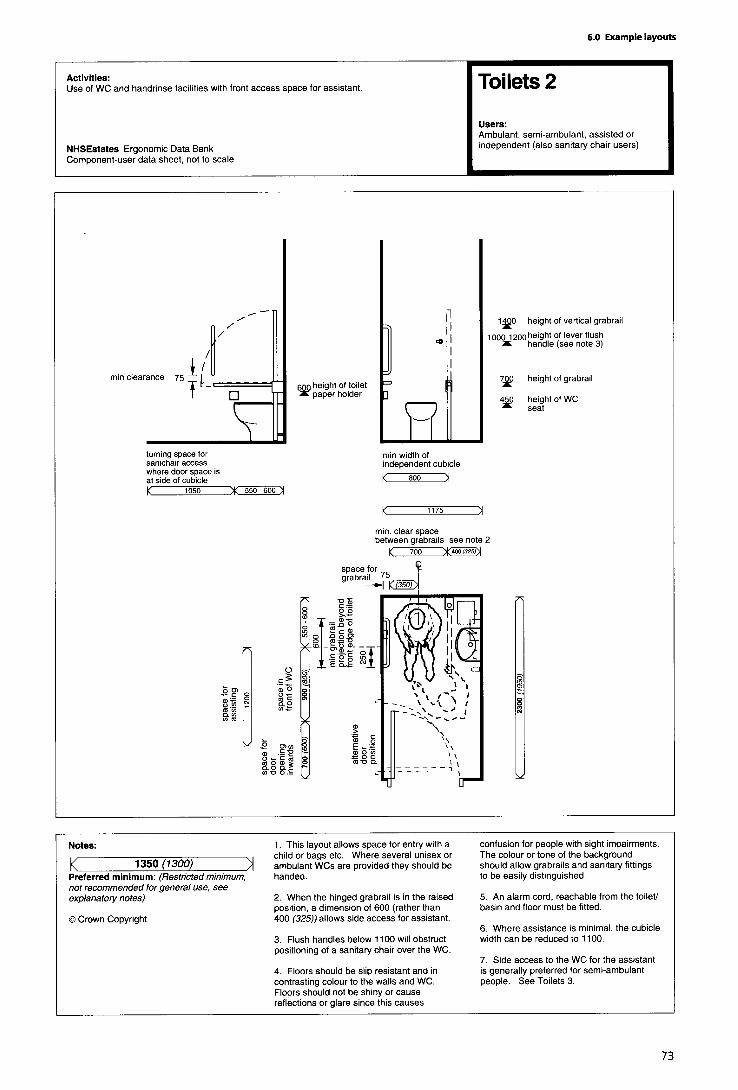


6.7 Waiting/refreshment areas
In areas where patients sit for the purpose of waiting and/orto take refreshment, the type of chairs chosen should allowpeople with different needs to sit in comfort. In particular,older people, in addition to those with mobility problemsand pregnant women, will require chairs with high seats,high backs and armrests to enable them to get into and outof them easily. Nursing mothers and those accompanyingchildren may require chairs with low seats; other users maybe accommodated on more basic types of chairs.
Chair coverings should provide comfort, but at the sametime be easy to wipe clean.
In designing a waiting/refreshment area, it is sensible toavoid a layout which has chairs placed in rows or round theedges of walls, as this can make people feel uncomfortableand nervous; in these areas, it is best to arrange chairs insmaller groups instead.
It is necessary to provide adequate space for those usingwalking aids or wheelchairs, and those with pushchairs, tonegotiate the spaces between chairs, Space will need to beallocated so that those in wheelchairs may sit alongsideothers.
In refreshment areas, wheelchair users will require sufficientspace to comfortably access the refreshment dispensingmachines, service counters and tables.
Furniture used in these areas should contrast in colour andtone to the floor surface, in order that visually-impairedpeople are able to identify the furniture and avoid anypossible trip hazard. If possible, crockery should contrast incolour/tone with the table surface; this can be achieved byusing dark or light tablecloths or placemats.
Waiting/refreshment areas should be adequately lit, notonly in order to enable visually-impaired people to negotiatetheir way, but also to make the area feel bright andcheerful. All information signs and notices should be easilyvisible (further guidance is available in the ‘Signposting’data sheets, and associated notes, earlier in this volume).


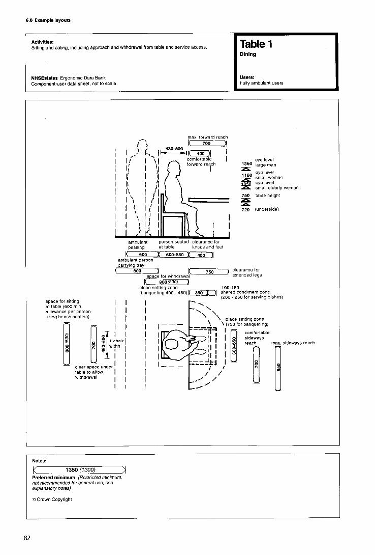


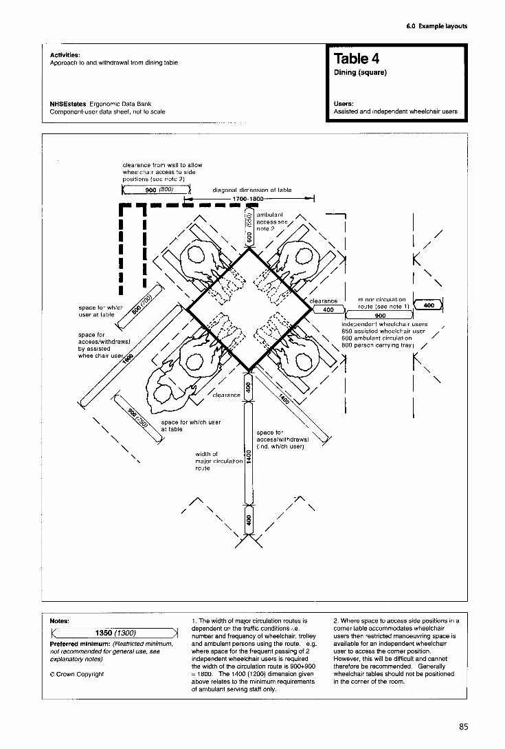
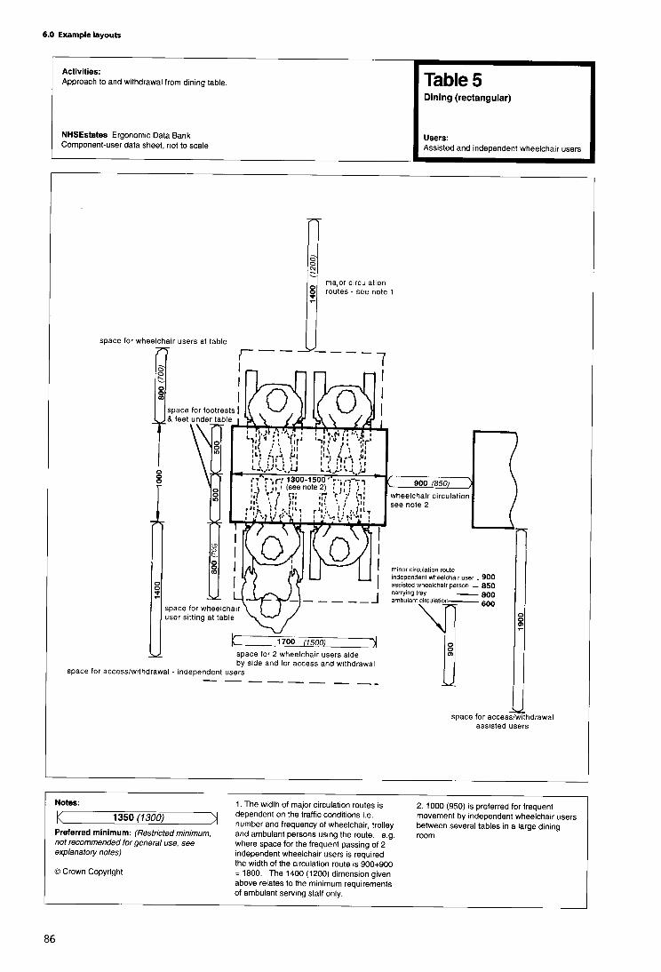

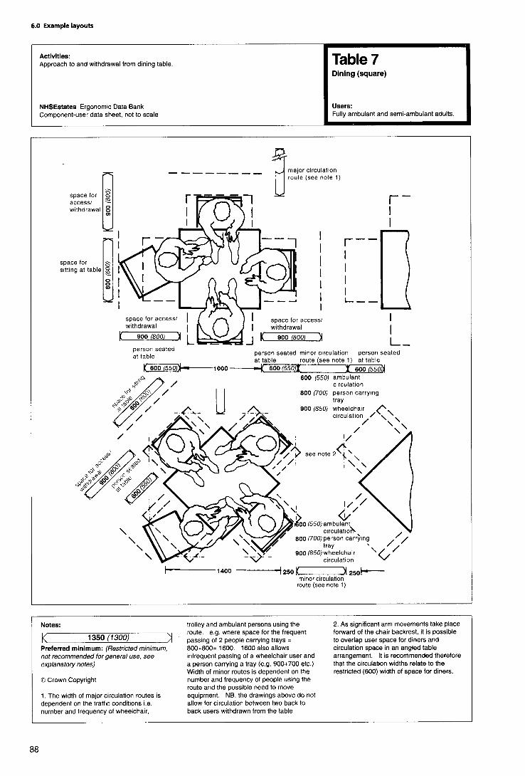


6.8 Components
This section contains a selection of component-user datasheets relating to commonly occurring components.The data sheets give dimensional and other ergonomicinformation about the use of individual components.


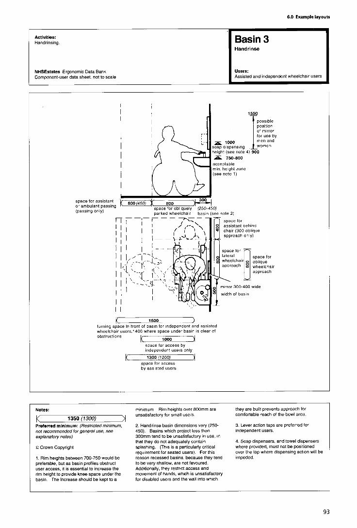
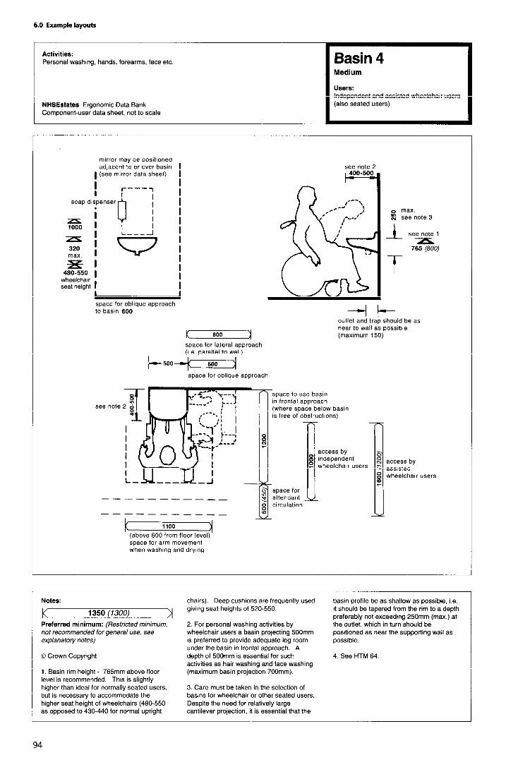

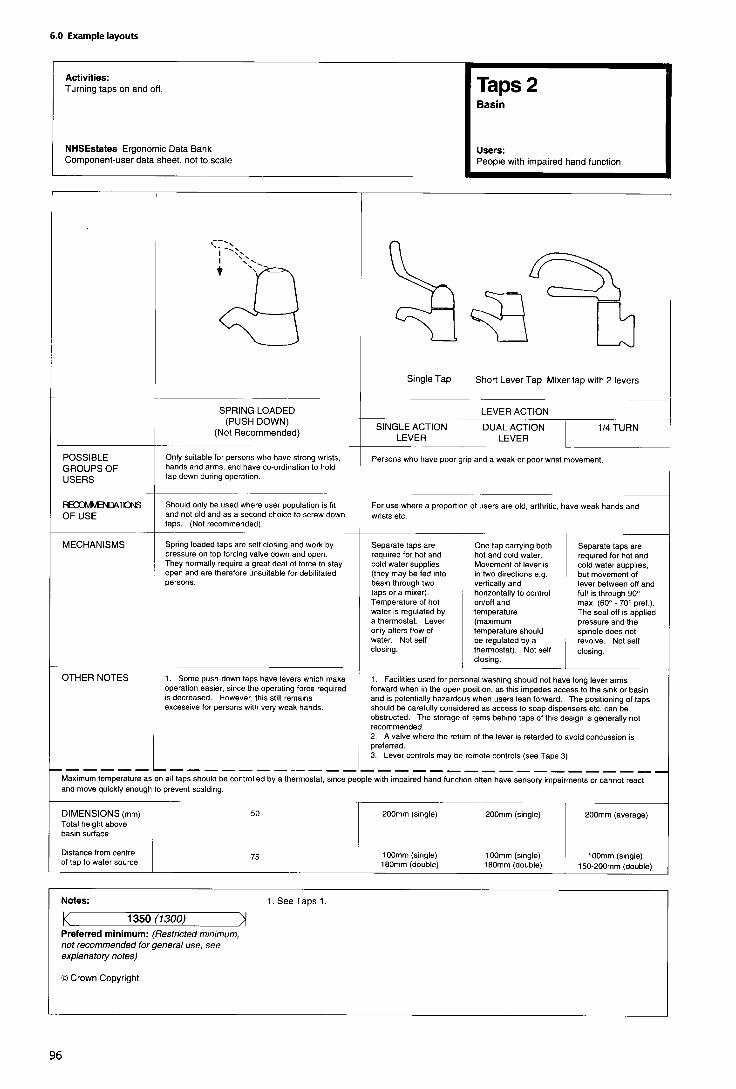


Telephones
(Notes to ergonomic data sheet)
General considerations
1. Telephones are required in public areas of healthbuildings, to enable people to contact relatives, call taxisetc. The people using them may be feeling ill or shocked,and may need to sit down to make the call; they may use awheelchair, a walking stick or crutches, or be hard ofhearing. It is easier for a taller able-bodied person to benddown or sit down to make a call than it is for a wheelchairuser or someone sitting to reach up for the handset or toinsert coins or a phonecard. Where space is limited,therefore, the telephone should be fixed at the lowerheight; where more than one telephone is provided, thesemay be fixed at a range of heights.
2. Telephones should be fitted with inductive couplers;telephones usable by people with hearing impairmentsshould be clearly marked with the appropriate symbol.
3. Where possible, telephones should be located in quietareas and be fitted with acoustic hoods.
4. A shelf should be provided adjacent to the telephoneapparatus, for placing such items as handbags, purse,wallets, notes of telephone numbers, etc whilsttelephoning.
5. A tip-up seat should be provided for those feeling ill orshocked, so that they may sit down while making the call;grabrails should be provided, to enable those withweakness to steady their balance and provide support whilststanding, sitting down and getting up.
6. If more than one type of telephone is provided -forexample, coin operated, phonecard or taxi call -at least oneof each should be accessible both to wheelchair users andto those who have hearing impairments.


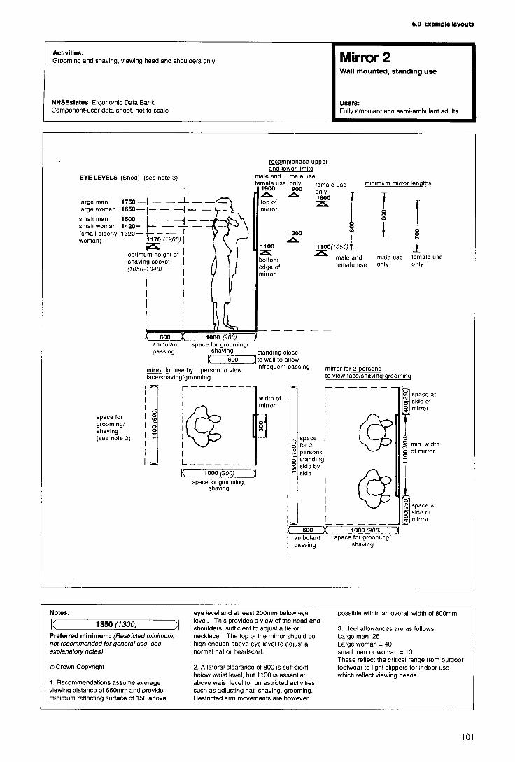
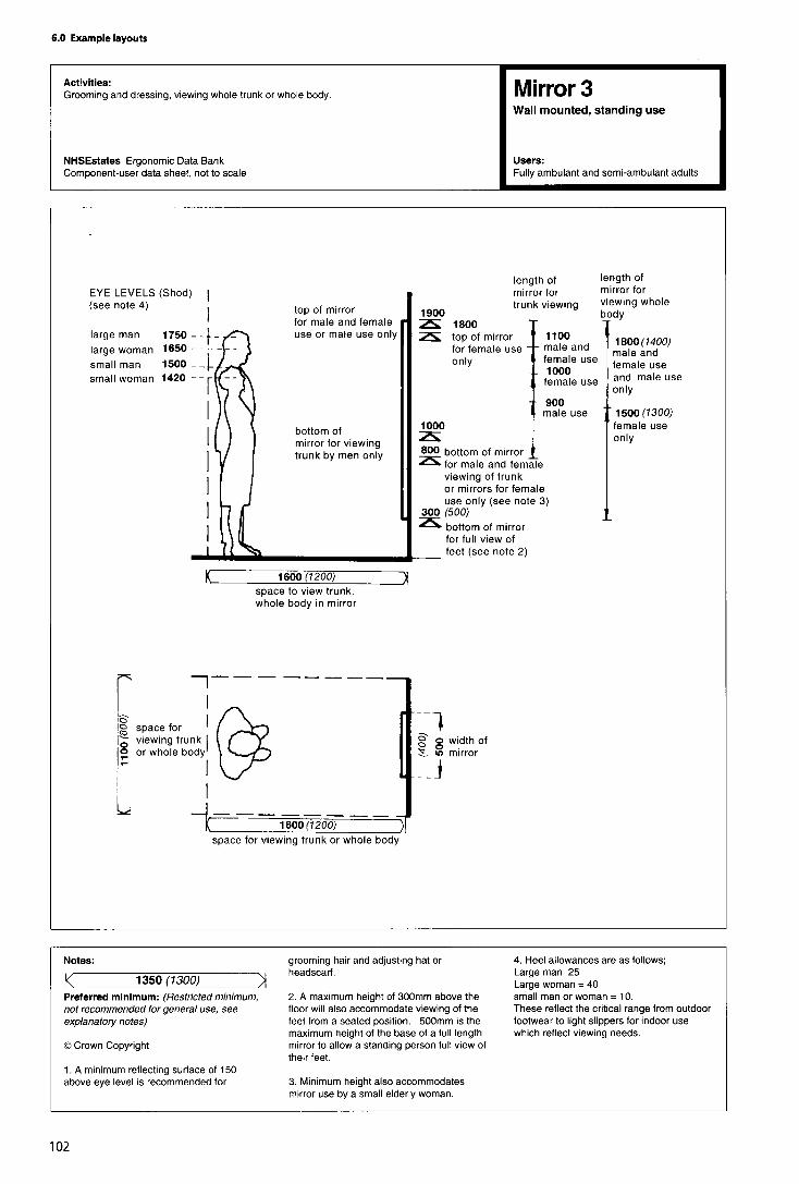
Windows
General considerations
1. Reference should be made to HTM 55 ‘Windows’.
2. Windows have two basic functions: they provide a viewof the external environment, and they may allow a room’soccupants to control ventilation. Daylight is important, butpatients in bed require privacy and should also be protectedfrom draughts.
3. Windows should be positioned to avoid glare anddazzle, which can cause discomfort, especially to visually-impaired people. In this connection, the fitting of adjustableblinds to control daylight and glare is recommended,though tinted glass or some other form of anti-glaretreatment can also be helpful (especially for south-facingwindows). Any large areas of glass should be marked by acoloured strip at least 150 mm wide, positioned at eye level(1200-1400 mm from the floor), as well as by a colouredframe, especially in circulation areas.
Approach space
4. A clear space is required in front of a window (includingsufficient room for forward approach by a person in awheelchair), in order to gain easy access for opening andclosing.
Height
5. To enable those seated in a chair/wheelchair or lying inbed to look out, windows should start at a height of600 mm above floor level; for offices etc, a height of900 mm from the floor is acceptable. The recommendedminimum height for the upper limit of windows is 2000 mmabove floor level. Transoms should be at a minimum heightof 1800 mm, in order not to impede sightlines.
Hardware
6. Where windows are designed to open, the handles andcatches must be easy for adults to use, but at the same timenot so easy that children can open them and fall out. It willtherefore be necessary to fit guard rails to any windows onthe first floor and above in health buildings. Additionally,any outward-opening windows on the ground floor of abuilding can present a hazard to visually-impaired people, ascan inward-opening windows at head height. Similarly, forsafety reasons, any glazing below a height of 850 mmshould not be openable. Glass areas should not extend tofloor level, therefore, as there is a danger of them beingkicked and possibly broken.
7. As a general rule, window handles etc should bepositioned for maximum accessibility. Handles and locksshould be easy to grasp with one hand, and should notrequire a pinch grip, tight grasp or extensive twisting of thewrist to operate. It is recommended that handles are of aminimum length of 110 mm, with a circular cross section toa minimum diameter of 15 mm. The clearance between the
handle and window or window frame must be a minimumof 40 mm; where possible, 60 mm is recommended.
8. Any devices for closing curtains and blinds (such as leverhandles or push/pull bars) should also be located within therecommended height range for handles. (Lever handlesshould be between 350 mm and 500 mm from the cornerof the window,) To enable high windows to be openedfrom below, extension handles-for example, for thoseabove sinks in kitchens and bathrooms - should be fitted.
9. Windows with two handles which need to be operatedsimultaneously-for example, those of the sash type -should be avoided.
Force required to open
10. Side-hanging and horizontally-pivoted windows arethe easiest to operate. Windows requiring pushing, pullingor lifting should require a maximum of 22.2 N force to openor close; the maximum torque to operate any windowfurniture should be 5.4 N.
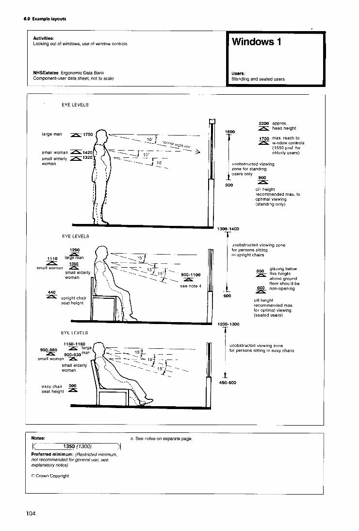


Appendix 1
Healthcare premises: check-list of access
and facilities for disabled people
Parking
1. Are there parking spaces adjacent to the building(s) tominimise the distances to be travelled?
2. Is parking space wide enough to allow car door to openfully to allow unobstructed transfer into a wheelchair, eitherunassisted or assisted?
3. Is the location of the disabled parking spaces such thatthe approach route to the building/facility is not obstructedby other parked cars and away from moving traffic?
4 . Are kerbs and other changes of level ramped?
5. Is the parking space and access route under cover?
6. Are there adequate signs to identify the reservedparking spaces and the best routes into the premises?
Approach to building
7. Is the approach route smooth, slip resistant (whetherwet or dry), free from incidental obstructions or hazards?
8 . Are handrails provided on all slopes and resting placesprovided at intervals where a ramp or approach is long?
9. Are all public entrances to the building/facilityaccessible?
10. Are access doors wide enough to facilitate wheelchairmovement?
11. Are thresholds eliminated or kept to a minimum?
1 2 . Do door characteristics and dimensions of relatedspaces allow it to be opened (and closed) easily byindependent wheelchair users, moving in either direction?
13. What doors can be eliminated?
Internal circulation
14. Are lobby sizes adequate and safe both forindependent and assisted wheelchair use?
15. Are corridor and approach routes satisfactory? Dothey allow passing and turning and take adequate accountof corridor traffic conditions?
16. Have all obstructions and projections from walls (orceiling) or similar hazards at floor level -such as changes oflevel-been avoided? If unavoidable are they clearlydiscernible?
17. Are internal door widths adequate to allow turningthrough 90º from the corridor or lobby? Should either orboth be increased?
18. Have safety handrails been provided on corridors,ramps, steps or at other points where they are required bypersons with impaired mobility? Have they been producedwhere they can be used as location aids by visually impairedpeople?
19. Are any large areas of glass close to circulation areasmarked or framed so as to be clearly discernible to partiallysighted people?
20. Are seats available at intervals to permit an ambulantdisabled and elderly person to take a short rest when facedwith long corridors to negotiate?
Vertical circulation
21. Are staircases safe and optimally comfortable forelderly and disabled people? Are handrail and landingcharacteristics satisfactory?
22. Are lifts available, conveniently placed, accessible andclearly signed?
23. Are lift controls accessible to the independentwheelchair user? Are the visual and audible signals, alarmsand floor designations satisfactory? Are digits embossedand satisfactory for blind or partially sighted persons? Isthere a tip-up seat, or a support rail available?
Toilets
24. Are there correctly designed unisex toilets, that is,where a husband and wife may enter the cubicle together,available in the public areas of the premises?
25. Are there suitable cubicles for wheelchair users inother male and female toilets in the building?
26. Do cubicles for wheelchair users provide adequatemanoeuvring space within, or is turning space providedoutside? Is the level of privacy afforded satisfactory?
27. Are there cubicles available with appropriate grabrailsfor the use of ambulant disabled people?

28. Are the WC and wash-basin arrangements accessibleto independent wheelchair users? Are the grabrails, mirrors,towels, door closing bars and other aids placedsatisfactorily?
Out-patient and treatment areas
29. Can ambulances discharge patients under coverwithin close proximity of the entrance? Are waiting areasprotected from draughts as patients move in and outthrough the entrance doors? Can patients usingwheelchairs (their own or hospital chairs whilst waiting fortreatment), sit with other patients without obstructing thecorridors or circulation area?
30. Can patients in wheelchairs use the reception deskconveniently and privately?
31. Are all consulting and treatment areas fully accessible?
32. Are there changing cubicles suitable for wheelchairusers, with room for assistance to be given if required?
33. Are refreshment areas accessible to disabled people?
34. Are clear, well lit, signs posted to ensure easycirculation within the building?
35. Are telephones and other public mechanismsaccessible to wheelchair users? Are knobs, dials, switches,handles and other controls operable and within convenientreach?
Ward facilities
36. Do sanitary facilities offer maximum independenceand privacy to disabled patients, both those who will beusing wheelchairs and those who have walking difficulties?
37. Is the day room accessible, with a variety of seatingheights to help ambulant disabled people? Are all noticesclear to see and understand?
38. Are window controls, radio and television and callbells easily reached by disabled patients?
39. Can disabled visitors conduct private conversationswith their friends in bed or in the ward?
Other features
40. Could disabled employees work in the building -withparticular reference to offices, laboratories, canteen, rest-rooms and toilet facilities?
41. Are emergency evacuation routes and emergencyexits satisfactory?
42. Are fire alarms readily accessible to the semi-ambulantand wheelchair disabled? Are emergency call facilitiesinstalled to summon assistance to remote locations?
43. Are audio/visual alarm signals provided?

Appendix 2
References The Building Regulations 1991: approved document K:stairs, ramps and guards. Department of theEnvironment, HMSO 1992.Acts
Consumer Protection Act 1987. HMSO 1987.The Building Standards (Scotland) Regulations 1990:Technical standards part S: stairs, ramps andprotective barriers. Scottish Office Building Directorate,HMSO 1990.
Chronically Sick and Disabled Persons Act 1970. HMSO1970.
Chronically Sick and Disabled Persons (Amendment)Act 1976. HMSO 1976. Health Circulars
Towards smoke-free NHS premises (HSG(92)41).Department of Health, 1992.Chronically Sick and Disabled Persons (Scotland) Act
1972. HMSO 1972.Health services management-security (HSG(92)22).Department of Health, 1992.Chronically Sick and Disabled Persons (Northern
Ireland) Act. HMSO 1978.Fire precautions in NHS premises: Firecode (HC(B7)24).Department of Health, 1987.Disabled Persons Act 1981. HMSO 1981,
Disabled Persons (Services, Consultation andRepresentation) Act 1986. HMSO 1986.
Upgrading and adaptation of existing buildings -revision of DS 183/74 (WK0(81)4). DHSS, 1981.
Disabled Persons (Northern Ireland) Act. HMSO, 1989. Damage in hospitals: need to buffer movableequipment (DS(Supply) 42/75). DHSS, 1975.
Health and Safety at Work etc Act 1974. HMSO 1974Capital Investment Manual
Overview. NHS Executive, HMSO 1994.Building Regulations and related publications
SI 2768: 1991 The Building Regulations. HMSO.Project organisation. NHS Executive, HMSO 1994.
SI 1180: 1992 The Building Regulations (Amendment)Regulations. HMSO.
Private finance guide. NHS Executive, HMSO 1994.
Business case guide. NHS Executive, HMSO 1994.SI 2179: 1990 (S 187) The Building Standards (Scotland)Regulations. HMSO 1990. Management of construction projects. NHS Estates,
HMSO 1994.The Building Regulations (Northern Ireland) 1990 -Part R: Facilities for disabled people. Department of theEnvironment for Northern Ireland, HMSO 1994.
Commissioning of a health care facility. NHSExecutive, HMSO 1994.
The Building Regulations (Northern Ireland) 1990 -Technical booklet R: Access and facilities for disabledpeople. Department of the Environment for NorthernIreland, HMSO 1994.
IM&T Guidance. NHS Executive, HMSO 1994.
Post project evaluation. NHS Executive, HMSO 1994
NHS Estates publications
The Building Standards (Scotland) Regulations 1990:Technical standards part T: facilities for disabledpeople. Scottish Office Building Directorate, HMSO 1990.
Works Guidance Index. NHS Estates, published annually.
National Health Service Model EngineeringSpecifications. NHS Estates, 1993, 1995.(2 vols mechanical; 2 vols electrical)The Building Regulations 1991: approved document
M: access and facilities for disabled people. Departmentof the Environment, HMSO 1992.

“Safe” hot water and surface temperatures (HealthGuidance Note). NHS Estates, HMSO 1992.
Health Building Notes (HBNs)
HBN 45 - External works for health buildings. NHSEstates, HMSO 1992.
HBN 48 - Telephone services. NHS Estates, HMSO 1990.
Health Technical Memoranda (HTMs)
HTM 17 - Health building engineering installations:commissioning and associated activities. DHSS, 1978.(out of print)
HTM 55 - Building components: Windows. NHS Estates,HMSO 1989.
HTM 56 - Building components: Partitions. NHS Estates,HMSO 1989.
HTM 57 - Building components: Internal glazing. NHSEstates, HMSO 1995.
HTM 58 - Building components: Internal doorsets. NHSEstates, HMSO 1989.
HTM 59 - Building components: Ironmongery. NHSEstates, HMSO 1989.
HTM 60 - Building components: Ceilings. NHS Estates,HMSO 1989.
HTM 61 - Building components: Flooring. NHS Estates,HMSO 1995.
HTM 62 - Building components: Demountable storagesystems. NHS Estates, HMSO 1989.
HTM 65 - Building components: Health signs. NHSEstates, HMSO 1995.
HTM 2007 - Electrical services: supply and distribution.NHS Estates, HMSO 1993.
HTM 2011 - Emergency electrical services. NHS Estates,HMSO 1993.
HTM 2014 - Abatement of electrical interference. NHSEstates. HMSO 1993.
HTM 2015 - Bedhead services. NHS Estates, HMSO 1995.
HTM 2023 - Accommodation for plant and services.NHS Estates, HMSO 1995.
HTM 2025 - Ventilation of healthcare premises. NHSEstates, HMSO 1995.
HTM 2027 - Hot and cold water supply, storage andmains services. NHS Estates, HMSO 1995..
HTM 2055 - Telecommunications (Telephoneexchanges). NHS Estates, HMSO 1994.
HTM 2040 - The control of legionellae in healthcarepremises-a code of practice. NHS Estates, HMSO 1993.
Firecode
Firecode: Policy and principles. NHS Estates, HMSO1994.
Firecode: Directory of fire documents. Department ofHealth, HMSO 1987.
Firecode in Scotland: Policy and principles. ScottishHome and Health Department, HMSO 1994.
Fire safety: new health buildings in Scotland. ScottishHome and Health Department, HMSO 1987.
The guide to means of escape and related safetymeasures in existing houses in multiple occupation inScotland. Scottish Home and Health Department, HMSO1988.
HTM 81 - Fire precautions in new hospitals. DHSS,HMSO 1987.
HTM 81 Supplement 1 -Fire precautions in newhospitals. NHS Estates, HMSO 1993.
HTM 82 - Firecode: alarm and detection systems. NHSEstates, HMSO 1989.
HTM 83 - Fire safety in healthcare premises: generalfire precautions. NHS Estates, HMSO 1994.
HTM 85 - Fire precautions in existing hospitals. NHSEstates, HMSO 1994.
HTM 86 - Fire risk assessment in hospitals. NHS Estates,HMSO 1994.
HTM 87 - Firecode: textiles and furniture. NHS Estates,HMSO 1993.
HTM 88 - Fire safety in health care premises. DHSS,HMSO 1986.
Fire Practice Note 1 - Laundries. Department of Health,HMSO 1987.
Fire Practice Note 2 - Storage of flammable liquids.Department of Health, HMSO 1987.
Fire Practice Note 3 - Escape bed lifts. Department ofHealth, HMSO 1987.

Fire Practice Note 4 - Hospital main kitchens. NHSEstates, HMSO 1994.
Fire Practice Note 5 - Commercial enterprises onhospital premises. NHS Estates, HMSO 1992.
Fire Practice Note 6 -Arson prevention and control inNH5 healthcare premises. NHS Estates, HMSO 1994.
Department of Health publications
Noise control (Hospital Design Note 4). Ministry ofHealth, HMSO 1966 (out of print, currently under revision).
Hospital Design Note 4 (noise control): amendmentsto appendices II, IV, VII (HN(76)126). DHSS 1976.
A report on noise and vibration (Engineeringdatasheet DH1). DHSS 1976.
Plumbing and public health: vertical drainage(Engineering datasheet EA5.1). DHSS 1975.
Plumbing and public health: horizontal drainage(Engineering datasheet EA5.11). DHSS 1978.
Scottish Office Circulars
Scottish Office: health building procurement inScotland: procedures prior to approval in principle(SHHD/DGM(87)13). Scottish Home and HealthDepartment, 1987.
Scottish Office: health building procurement inScotland: principles of cost control (SHHD/DS(85)58).Scottish Home and Health Department 1985.
Health building procurement in Scotland:procurement procedures for health buildings (SHHD/DGM(91)38). Scottish Home and Health Department 1985
Health building procurement in Scotland: proceduressubsequent to approval in principle. Scottish Home andHealth Department, 1992.
Health and Safety Executive publications
Display screen equipment work: Health and Safety(Display Screen Equipment) Regulations 1992:guidance on regulations (L26). Health and SafetyExecutive 1992.
British Standards
854533: Luminaires.
BS5394: 1988 Specification for limits and methods ofmeasurement of radio interference characteristics offluorescent lamps and luminaires. (AMD 6581, 8/90)
855572: 1994 Code of practice for sanitary pipework.
855588: Fire precautions in the design, constructionand use of buildings.
BS1 Part 8:1988 Code of practice for means of escapefor disabled people.
BS5810:1979 Code of practice for access for thedisabled to buildings.
BS7671:1992 Requirements for electricalinstallations. IEE Wiring Regulations. Sixteenthedition.
Miscellaneous publications
Lighting guide: hospitals and health care buildings(LG2). Chartered institute of Building Services Engineers(CIBSE), 1989.
The use of dropped kerbs and tactile surfaces atpedestrian crossing points (Advice Note 00/1/91).Mobility Unit, Department of Transport 1992.
855266: Emergency lighting.

Appendix 3
Further reading
Foley, Conor and Pratt, Sue. Access denied: human rightsand disabled people. National Council for Civil Liberties,1994.
George, Mike. Grabbing some attention. CommunityCafe, 1994, Jan 20, no 1000, pp 14-15.
Ratoff, Len, Heyes, Janet and Haddleton, Maxine. Does youdon’t have access? Health Service Journal, 1993, Apr 29,vol 103, no 5350, pp 32-34.
Jellicoe, Lynne. Access all areas. Health Service Journal,1993, Jul 15, vol 103 ,no 5361, p31.
Parker, Gillian and Beales, David. Provision to reflect realneeds. Meeting the needs of disabled people ingeneral practice. Professional Nurse, 1993, Sep, vol 8, no12, pp 820-822, 824, 825.
Braddock, Andrew and Selling, Neil. Risking access?,Access by Design, 1993, Sep/Dec, no 62, pp 12-14.
Penton, John. Access to housing. Architects Journal, 1993,Jan 20, vol 197, no 3, p 43.
Thorpe, Stephen. Coggeshall, Essex. Access by Design,1993, Jan/April, no 60, pp 6-9.
Harrowell, Chris and Peace, Su. Fire escape strategies fordisabled people. Access by Design, 1993, Jan/Apr, no 60,pp 17-21.
Lappin, Nicky. Coming clean on bathrooms. Access byDesign, 1993, Sep/Dec, no 62, pp 10-11.
Thorpe, Stephen and Alderson, Ann. Access to existingbuildings. Access by Design, 1992, May/Aug, no 58, p 18.
Millington, David. Automatic access. Building, 1992, Oct30, vol 257, no 7768, supplement, pp 27, 28.
Tate, John and O’Farrell, Neil. Access developments indoctors’ surgeries. Access by Design, 1992, Sep/Dec, no59, pp 16, 17.
Doughty, Richard. Surgery design goes according toopen-plan. Medeconomics, 1992, Apr, vol 13, no 4, pp58-60, 62.
Council on Tall Buildings and Urban Habitat. Buildingdesign for handicapped and aged persons. McGraw-Hill, 1992. Unpriced.
Cooke, G M E. Assisted means of escape of disabledpeople from fires in tall buildings (BRE informationpaper; IP 16/91). Building Research Establishment, 1991.
Cornelissen, Gerard JJ. European perspectives. Contact,1991, Spring, no 67, pp 17, 19, 20.
Walsh, C J. A step backwards for barrier-free design?Access by Design, 1990, Jan/Apr, no 51, pp 6-9.
Planning for a brighter Wandsworth: access tobuildings and spaces for people with disabilities.Wandsworth Borough Planner’s Service, 1989.
Facilities for the disabled: a PSA building design guide.Property Services Agency. Directorate of ArchitecturalServices, Building Research Establishment, 1989.
Vujakovic, Peter. Mapping another world. Access byDesign, 1992, Jan/Apr, no 57, pp 14-16.

Appendix 4
Activity Data
1. “Activity data” is an information system developed tohelp project and design teams by defining the users’ needsmore precisely. This information constitutes thecomputerised Activity DataBase, which is updated twiceyearly. It comprises three types of information sheet: activityspace data sheets (known as A-Sheets), their supportingactivity unit data sheets (known as B-Sheets) and A-Sheetcomponent listings (known as D-Sheets).
2. A-Sheets record in more detail than is described in thisNote each task or activity that is performed in a particularactivity space (which may be a room, space, corridor or bay),together with environmental conditions and the technicaldata necessary to enable the activities to be performed.Each A-Sheet also contains a list of the titles and codenumbers of the relevant B-Sheets.
3 . B-Sheets provide narrative text and graphics to scalerelating to one activity. They show equipment fitted orsupplies as part of the building, and also the necessaryengineering terminals.
4. D-Sheets provide information about the total quantitiesof components (excluding those in Group 4 -see paragraph1.12) extracted from all B-Sheets selected for inclusion in anindividual A-Sheet.
5 . Activity data is only available in the form of magneticmedia, but this may be used to generate paper copieswhere required.
6 . Further information about the use and preparation ofactivity data can be obtained from NHS Estates, Departmentof Health, 1 Trevelyan Square, Boar Lane, Leeds LSl 6AE.
Activity data applicable to this Note
7 . The A-Sheets recommended for the activity spacesdescribed in this Note are either new sheets, amended onesor selected from existing sheets. A list of A-Sheet codenumbers and titles is given at the end of this chapter.
8 . Further activity data sheets may be selected, or drawnup by project teams to their own requirements, for anyservices not described in the Note or included in the list.
Lists of activity data A-Sheets
10. The activity data A-Sheets listed below may not carry atitle identical to the activity spaces detailed in this Note. Useof the appropriate A-Sheet code number will, however,result in the correct activity space being accessed.
11. The activity data A-Sheets are listed below in the sameorder as the spaces to which they relate are listed in theSchedule of Accommodation.
Note The foregoing applies to the MS.DOS applicationonly. During the currency of this Note an MS.Windowsapplication is being introduced with the followingconsequences:
A-Sheets are replaced by room data sheets;
B-Sheets are replaced by assemblies;
the term ‘D-Sheets’ is omitted from componentlistings.
9. In order to ensure consistent and economic provision,variations from the A-Sheets recommended for the spacescovered in this Note should be considered only where it hasbeen decided that the function of a space will differsubstantially from that described.

Activity space A-sheet code
WC/Rinse basin: fully ambulant usersWC/Rinse basin: ambulant, semi and assisted ambulant, frontal accessWC/Rinse basin: ambulant, semi and assisted ambulant, lateral accessWC/Rinse basin: independent wheelchair users, ‘Specimen’ WCWC/Rinse basin: independent and assisted wheelchair usersWC/Rinse basin: assisted wheelchair users, dual accessWC/Bidet/Wash basin: independent semi, and assisted ambulant usersBathroomMKNVashBathroom/WC/Wash: treatment, assisted patient, use of hoistShower: ambulant staff usersShower/WC/Wash: assisted patient wheelchair usersShower/WC/Wash: assisted patient wheelchair usersShower/WC/BidetANash
V1007V1101V1102V0906V0904V1214V1209V1709V1714V0801V1608V1612V1620

Appendix 5
Index of Data Ergonomic Sheets in othervolumes of HBN 40
Volume 2 - Treatment areas
Consulting/examination/treatmentConsulting/examination room-General Type 1Consulting/examination room-General Type 2Consulting/interview roomExamination room 1Treatment room 1
Bed/cot careBed, variousBed, divanSingle bedroom 1Single bedroom 2Single bedroom 3Single bedroom 4Twin bedroom 1Bed space4 bed space6 bed space
Patient hoistsPatient Hoist 1, mobile chair (wide or narrow base) turning9 0 ”Patient Hoist 2, mobile chair turning 90” + 180”Patient Hoist 3, mobile chair (wide or narrow base) to andfrom bathroomPatient Hoist 4, with chair attachment, drying and dressingpatientPatient Hoist 5, mobile chair hoist, manoeuvring into andout of bath
To i le tsToilet 2, ambulant, semi- and assisted ambulant-frontalaccessToilet 3, ambulant, semi- and assisted ambulant - lateralaccessToilet 4, independent wheelchair users, with basinToilet 5, independent and assisted wheelchair users, withbasinToilet 6, dual assisted wheelchair users, with basinToilet 7, WC with bidet and basin
BathroomsBathroom 1, ambulant, assisted ambulant and independentwheelchair patients; WC and personal washing facilityBathroom 2, assisted patients; use of hoist, WC andpersonal washing facility
ShowersShower 1, partially capable users with assistance andwheelchair users; with WC and wash basin -linear layoutShower 2, partially capable users with assistance andwheelchair users; with WC and wash basin-- non-linearlayoutShower 3. shower/WC/bidet
ComponentsDesk 1, Doctor’s, with drawers on one sideChair 3, upright; sitting, assisted and independent changingPerson 8, dressing/undressingLow partition, bed-space privacy screenSwitches and sockets, wall-mountedDoor Screen 1, single door, 1000 + 900 doorsetsDoor Screen 2, 1500 doorsetsBidet, ambulant or semi-ambulant patientsBath 1, wheelchair accessBasin 1, handrinseBasin 2, medium; personal washingBasin 3, handrinse (wheelchair users)Basin 4, medium (wheelchair users)Basin 5, medium; clinical washing (Staff users)Taps 1, basinTaps 2, basinTaps 3, basinWardrobe 1, clothes storage (wheelchair users)Shelving 3, open 200 deep (wheelchair users)Worktop Bench 3 (independent or assisted wheelchairusers)Cupboard 3, wall-mounted (wheelchair users)Drawers 1, Independent and wheelchair usersSink 1 (wheelchair users)Sink 2, Laundry (wheelchair users), lateral approachSink 3, Laundry (wheelchair users), frontal approachSink 4, stainless steel, single with draining-board (generaluse)Ironing board 1 (partially capable, standing or seated users)Ironing board 2 (assisted and independent wheelchair users)Oven 1, smallCooking hob 1, smallRefrigerator 1Washing-machine 1, front-loadingPlanting bed 1 (partially capable users)Planting bed 2 (wheelchair users)Planting bed 3 (wheelchair users)
Volume 3 - Staff areas
Reception area -generalStaff base-wardPantryInterview room / relatives’ accommodationSeminar room

Utility spaces and disposalClean utility- in-patientDirty utility- generalDisposal room
Cleaning spacesCleaning space-generalCleaning space-team/heavy duty
OfficesOffice 1 -generalOffice 2 -senior staffOffice 3 -all disciplinesOffice 4 -medical, Doctor’s officeOffice 5 -medical, head of divisionOffice 6 -medical, 2 senior staffOffice 7 -interview/overnight stay
ToiletsToilet 1, fully ambulant, with basinToilet 2, ambulant, semi- and assisted ambulant-frontalaccessToilet 3, ambulant, semi- and assisted ambulant - lateralaccessToilet 4, independent wheelchair users, with basinToilet 5, independent and assisted wheelchair users, withbasin
ShowersShower 4, ambulant staff users
ComponentsX-ray illuminatorDesk 2, single pedestal (1200 x 700)Chair 1, uprightChair 4, semi-easy, low-backFiling cabinet 1-, 2-, 3- or 4-drawerFiling cabinet 2, 3 or 5 rails laterally suspendedShelving 1, racking, 200-300 deepShelving 2, racking, 450-600 deepShelving 3, open, 200 deep (wheelchair users)Worktop Bench 1Worktop Bench 2Worktop Bench 3, Independent and assisted wheelchairusersCupboard 1, Small, wall-mountedCupboard 2, Small, wall-mountedCupboard 3, Wall-mounted, Wheelchair usersCupboard 4, Low-levelDrawers 1, Independent wheelchair usersScreen/Board 1Screen/Board 2Person 8, Dressing/undressingSeat and clothes hooks; changingLocker 1, small luggageLocker 2, StaffSwitches & Sockets, wall-mountedSuction Cleaner, Cylinder-typeScrubber/PolisherBucket Trolley, Double, with wringerBasin 5, Medium; clinical washing (staff users)
Sack Holder, Large, mobileSink 4, Stainless steel, single with draining-board
Volume 4 - Circulation areas
Ambulant peoplePerson 1, walking -circulating and passingPerson 2, walking, with assistancePerson 3, with walking sticks or tripods, and assistancePerson 4, with crutch or crutches, and assistancePerson 5, with walking frame
WheelchairsWheelchair 1, straight movementWheelchair 2, around cornerWheelchair 3, turningWheelchair 6, parking end to endWheelchair 7, parking side by sideCorridor-ambulant and wheelchair users: circulating andparking
Patient trolleysPatient trolley 1, straight movementPatient trolley 2, around cornerPatient trolley 3, through 1500 doorsetPatient trolley 4, through 1900 doorset
BedsBed 1, adjustable or fixed-height bed sizesBed 2, straight movement, with or without attendantsBed 3, through 1500 doorsetBed 4, through 1900 doorsetBed 5, turning 90° cornerBed 6, turning through 180° corner
LobbiesLobbies 1, Single-leaf doorsLobbies 2, Double-leaf doorsLobbies 3, Automatic sliding doors
Lifts and stairsLift and Controls - passenger, 1600 x 1400Lift-multi-purpose stretcher/trolley, 1400 x 2400Lift - bed, 1800 x 2700Internal stairsStaircase, mattress evacuation 1: straight flight-corridorsStaircase, mattress evacuation 2: landings and stairs
Trolleys/mobile equipment (large)Trolley/mobile equipment 1 -typesTrolley/mobile equipment 2 -typesTrolley/mobile equipment 3, straight movementTrolley/mobile equipment 4, around cornerTrolley/mobile equipment 5, through doors (1000 or 1200)Trolley/mobile equipment 6, though doors (1400 or 1800)Trolley/mobile equipment 7, turningTrolley/mobile equipment 8, parking at 90° to wallTrolley/mobile equipment 9, parking parallel to wallPlatform truck 1, straight movementPlatform truck 2, around corner and through doorway

Platform truck 3, turningPallet truck 1, straight movementPallet truck 2, around corner and through doorwayPallet truck 3, turningPallet truck 4, parkingSack truck 1, tilting, and straight movementSack truck 2, around cornerSack truck 3, through doorwaySack truck 4, turning
Tugs and trainsTug 1, basic dimensions; straight movementTug 2, turningTug 3, charging bayTug and train 1, straight movementTug and train 2, around corner, chamfer ATug and train 3, around corner, chamfer BTug and train 4, turning into an openingTug and train 5, turningTug and train 6, rampsTug and train 7, lay-by
Service ductsService duct 1, Horizontal crawlway - access hatchService duct 2, Horizontal crawlway - through routeService duct 3, Vertical shaft with ladderService duct 4, Step ladderService duct 5, Horizontal (floor/ceiling) hatchService duct 6, CatwalkService duct 7, Horizontal walkway with or without servicesService duct 8, Horizontal crawlway with services

Other publications in this series
(Given below are details of all Health/Hospital BuildingNotes which are either published by HMSO or inpreparation. A Design Briefing System Notebook is availablewith Notes marked (*) - information is given within theNotebook on how it may be used. Information is correct atthe time of publication of this volume.)
1234
5 -67
78
91011121212
-
-121313
1415161718
-
--
1920212223
242526272829
30313233
Buildings for the Health Service, 1988. HMSOThe whole hospital, 1992. HMSO-
Adult acute ward, 1990. HMSO
Radiology department, 1992. HMSOSupp 1 Ethylene oxide sterilization section, 1994.HMSO-
Rehabilitation: accommodation for physiotherapy,occupational therapy and speech therapy, 1991.HMSO
Catering department, 1986. HMSO*-
Out-patients department, 1986. HMSO*Supp 1 Genito-urinary medicine clinic. 1991. HMSO*Supp 2 Oral surgery, orthodontics, restorativedentistry, 1992. HMSOSupp 3 Ear, nose, throat (in preparation)Sterile services department, 1993. HMSOSupp 1 Ethylene oxide sterilization section, 1994.HMSO
Accomodaiton for pathology services, 1991. HMSO
Office accommodation in health buildings, 1991.HMSO-
Mortuary and post-mortem room, 1991. HMSOMaternity department, 1989. HMSO*Accident and emergency department, 1995. HMSOComprehensive children’s department, 1994.HMSO*-
Laundry, 1994. HMSOOperative department, 1991. HMSOIntensive therapy unit, 1992. HMSO-
Accommodation for pharmaceutical services, 1988.HMSO*
-
Rehabilitation centres for psychiatric patients, 1966.HMSO
34
35
3637
383940
41
42
4344
4546474849505151
52
Estate maintenance and works operations, 1992.HMSOAccommodation for people with acute mental illness,1988. HMSO*Local healthcare facilities, 1995. HMSOHospital accommodation for elderly people, 1981.HMSO-
Ophthalmic clinic, 1982. HMSOCommon activity spacesVol2 -Treatment areas, 1995. HMSOVol3 - Staff areas, 1995. HMSOVol4 - Circulation areas, 1995. HMSOAccommodation for staff changing and storage ofuniforms, 1984. HMSO*Accommodation for education and training, 1989.HMSO*-
Accommodation for ambulance services. 1994.HMSOExternal works for health buildings, 1992. HMSOGeneral medical practice premises, 1991. HMSOHealth records department, 1991. HMSOTelephone services, 1989. HMSO*-
Main entrance, 1991. HMSOSupp 1 Miscellaneous spaces in a District GeneralHospital, 1991. HMSOAccommodation for day careVol 1 - Day surgery unit, 1993. HMSOVol2 - Endoscopy unit, 1994. HMSOVol3 -Medical investigation and treatment unit,1995. HMSO
Health Building Notes published by HMSO can be purchasedfrom HMSO bookshops in London (post orders to PO Box276, SW8 5DT). Edinburgh, Belfast, Manchester,Birmingham and Bristol or through good booksellers.
Enquiries should be addressed to: The Marketing Unit,NHS Estates, Department of Health, 1 Trevelyan Square,Boar Lane, Leeds LS1 6AE.
The price of this publication has been set to make somecontribution to the costs incurred by NHS Estates in itspreparation.
--

About NHS Estates
NHS Estates is an Executive Agency of the Department ofHealth and is involved with all aspects of health estatemanagement, development and maintenance. The Agencyhas a dynamic fund of knowledge which it has acquiredduring 30 years of working in the field. Using thisknowledge NHS Estates has developed products which areunique in range and depth. These are described below.NHS Estates also makes its experience available to the fieldthrough its consultancy services.
Enquiries about NHS Estates should be addressed to:NHS Estates, Marketing Unit, Department of Health,1 Trevelyan Square, Boar Lane, Leeds LS1 6AE.Telephone 0113 254 7000.
Some other NHS Estates products
Activity DataBase - a computerised system for definingthe activities which have to be accommodated in spaceswithin health buildings. NHS Estates
Design Guides - complementary to Health Building Notes,Design Guides provide advice for planners and designersabout subjects not appropriate to the Health Building Notesseries. HMSO
Estatecode - user manual for managing a health estate.Includes a recommended methodology for propertyappraisal and provides a basis for integration of the estateinto corporate business planning. HMSO
Concode - outlines proven methods of selecting contactsand commissioning consultants. Reflects official policy oncontract procedures. HMSO
Works Information Management System - acomputerised information system for estate managementtasks, enabling tangible assets to be put into the context ofservicing requirements. NHS Estates
Health Guidance Notes - an occasional series ofpublications which respond to changes in Department ofHealth policy or reflect changing NHS operationalmanagement. Each deals with a specific topic and iscomplementary to a related HTM. HMSO
Health Technical Memoranda - guidance on the design,installation and running of specialised building servicesystems, and on specialised building components. HMSO
Health Facilities Notes - debate current and topical issuesof concern across all areas of healthcare provision. HMSO
Firecode - for policy, technical guidance and specialistaspects of fire precautions. HMSO
Capital Investment Manual Database - softwaresupport for managing the capital programme. Compatiblewith the Capital Investment Manual. NHS Estates
Model Engineering Specifications - comprehensiveadvice used in briefing consultants, contractors andsuppliers of healthcare engineering services to meetDepartmental policy and best practice guidance. NHSEstates
Quarterly Briefing - gives a regular overview on theconstruction industry and an outlook on how this mayaffect building projects in the health sector, in particular theimpact on business prices. Also provides information onnew and revised cost allowances for health buildings.Published four times a year; available on subscription directfrom NHS Estates. NHS Estates
Works Guidance Index - an annual, fully cross-referencedindex listing all NHS Extates publications and otherdocuments related to the construction and equipping ofhealth buildings. NHS Estates
Items notes “HMSO” can be purchased from HMSOBookshops in London (post orders to PO Box 276, SW85DT), Edinburgh, Belfast, Manchester, Birminghamand Bristol or through good booksellers.
NHS Estates consultancy service
Designed to meet a range of needs from advice on theoversight of estates management functions to a much fullercollaboration for particularly innovative or exemplaryprojects.
Enquiries should be addressed to: NHS Estates ConsultancyService (address as above).
Printed in the United Kingdom for HMSODd 300375 C15 3/95 O/65536 N316401 09/32271