status of solaris - lunds universitet€¦ · 2. next beamline phelix (soft x-ray beamline) was...
TRANSCRIPT
Arkadiusz [email protected]
On behalf of SOLARIS Team
Status of SOLARIS
Solaris National Synchrotron Light SourceJagiellonian UniversityCzerwone Maki 9830-392 Krakówwww.synchrotron.uj.edu.pl
The XXIV European Synchrotron Light Source Workshop, A. Kisiel, 28-30.11.2016, Lund, Sweden
Outline
Solaris overview
Previous year status
Curent status and problems during
commissioning
Near and far future
Summary
XXIV ESLS, A. Kisiel, 28-30.11.2016, Lund, Sweden
Solaris Overview
XXIV ESLS, A. Kisiel, 28-30.11.2016, Lund, Sweden
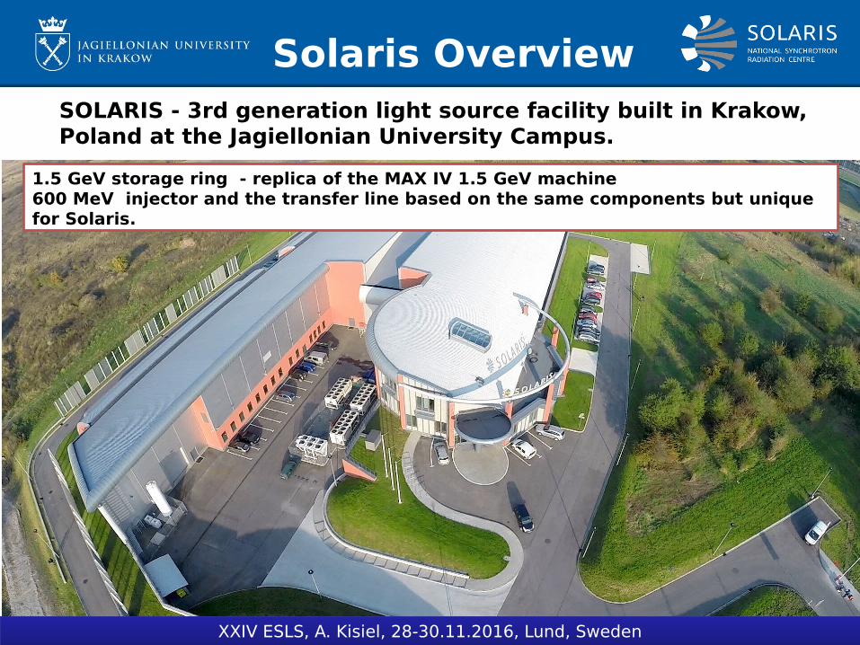
SOLARIS - 3rd generation light source facility built in Krakow, Poland at the Jagiellonian University Campus.
1.5 GeV storage ring - replica of the MAX IV 1.5 GeV machine 600 MeV injector and the transfer line based on the same components but unique for Solaris.
Solaris Overview
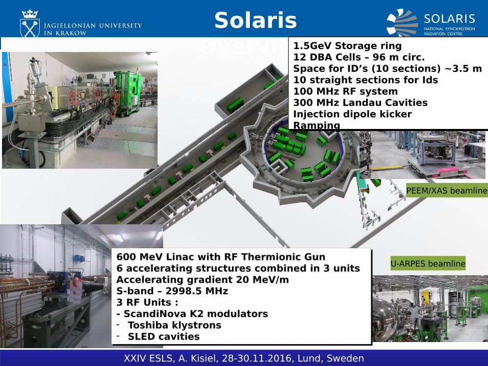
PEEM/XAS beamline
U-ARPES beamline
XXIV ESLS, A. Kisiel, 28-30.11.2016, Lund, Sweden
600 MeV Linac with RF Thermionic Gun6 accelerating structures combined in 3 unitsAccelerating gradient 20 MeV/mS-band – 2998.5 MHz3 RF Units :- ScandiNova K2 modulators- Toshiba klystrons- SLED cavities
600 MeV Linac with RF Thermionic Gun6 accelerating structures combined in 3 unitsAccelerating gradient 20 MeV/mS-band – 2998.5 MHz3 RF Units :- ScandiNova K2 modulators- Toshiba klystrons- SLED cavities
1.5GeV Storage ring 12 DBA Cells – 96 m circ.Space for ID’s (10 sections) ~3.5 m10 straight sections for Ids100 MHz RF system300 MHz Landau CavitiesInjection dipole kickerRamping
1.5GeV Storage ring 12 DBA Cells – 96 m circ.Space for ID’s (10 sections) ~3.5 m10 straight sections for Ids100 MHz RF system300 MHz Landau CavitiesInjection dipole kickerRamping
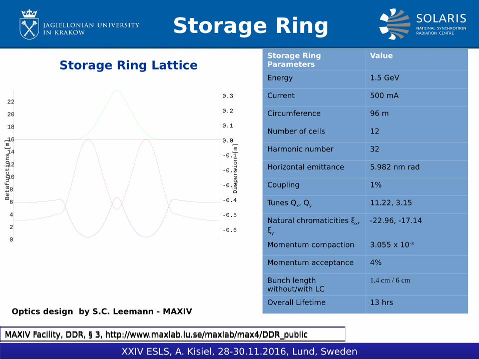
Storage Ring Lattice
Storage Ring
Optics design by S.C. Leemann - MAXIV
MAXIV Facility, DDR, § 3, http://www.maxlab.lu.se/maxlab/max4/DDR_publicMAXIV Facility, DDR, § 3, http://www.maxlab.lu.se/maxlab/max4/DDR_public
Storage Ring Parameters
Value
Energy 1.5 GeV
Current 500 mA
Circumference 96 m
Number of cells 12
Harmonic number 32
Horizontal emittance 5.982 nm rad
Coupling 1%
Tunes Qx, Qy 11.22, 3.15
Natural chromaticities ξx, ξy
-22.96, -17.14
Momentum compaction 3.055 x 10⁻³
Momentum acceptance 4%
Bunch length without/with LC
1.4 cm / 6 cm
Overall Lifetime 13 hrs
0 1 2 3 4 5 6 7 80
2
4
6
8
10
12
14
16
18
20
22
Betafunctions [m]
-0.6
-0.5
-0.4
-0.3
-0.2
-0.1
0.0
0.1
0.2
0.3
Dispersion [m]
XXIV ESLS, A. Kisiel, 28-30.11.2016, Lund, Sweden
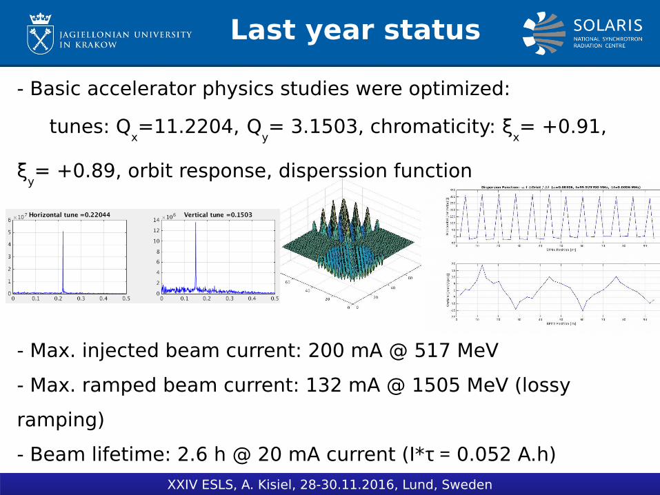
Last year status
XXIV ESLS, A. Kisiel, 28-30.11.2016, Lund, Sweden
- Basic accelerator physics studies were optimized:
tunes: Qx=11.2204,
Q
y= 3.1503, chromaticity: ξ
x= +0.91,
ξy= +0.89, orbit response, disperssion function
- Max. injected beam current: 200 mA @ 517 MeV
- Max. ramped beam current: 132 mA @ 1505 MeV (lossy
ramping)
- Beam lifetime: 2.6 h @ 20 mA current (I*τ = 0.052 A.h)
Last year aims
- Improvement of stored beam current at nominal energy
- Installation of Landau cavities
- Reducing RMS of closed orbit
- Starting of beamlines commissioning
- Beam lifetime improvement
XXIV ESLS, A. Kisiel, 28-30.11.2016, Lund, Sweden
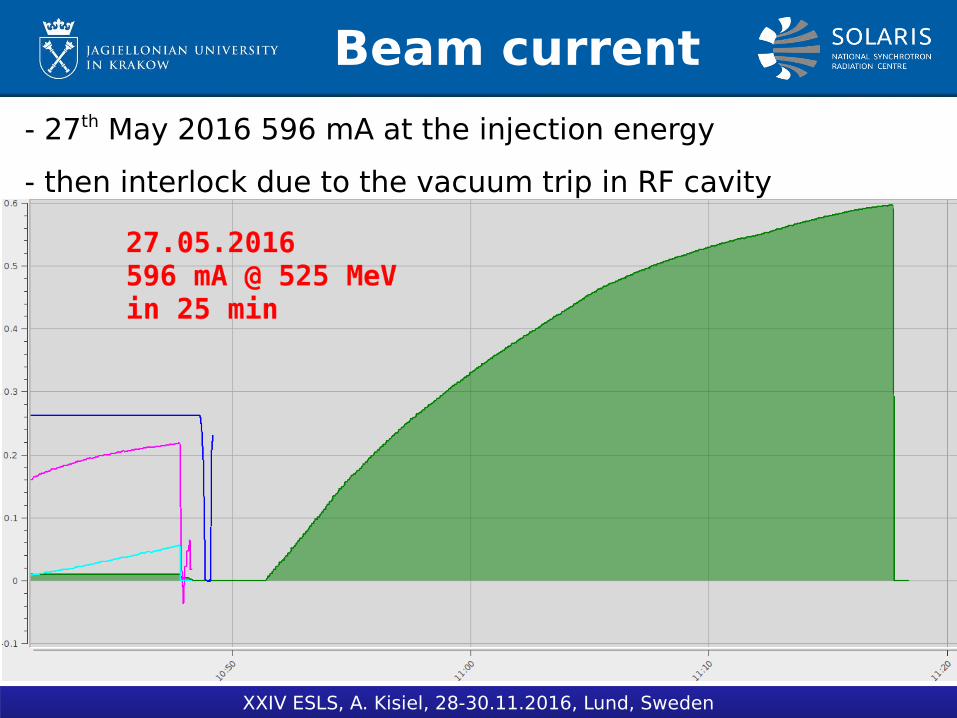
Beam current
- 27th May 2016 596 mA at the injection energy
- then interlock due to the vacuum trip in RF cavity
XXIV ESLS, A. Kisiel, 28-30.11.2016, Lund, Sweden
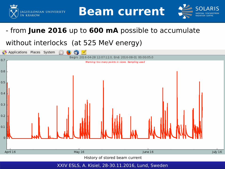
Beam current
- from June 2016 up to 600 mA possible to accumulate
without interlocks (at 525 MeV energy)
XXIV ESLS, A. Kisiel, 28-30.11.2016, Lund, Sweden
History of stored beam current

Beam current
- 9th June 2016:
408 mA ramped to final 1.5 GeV energy, I*τ = 0.62 A.h
- beam were stored for about 20 min then vacuum interlock in
main RF cavity occured
- then vacuum leak on first cavity were observed
XXIV ESLS, A. Kisiel, 28-30.11.2016, Lund, Sweden
0
100
200
300
400
500
I [mA] @ 525 MeV
I [mA] @ 1.5 GeV
Accumulated Beam Dose [A.h]
I [m
A]
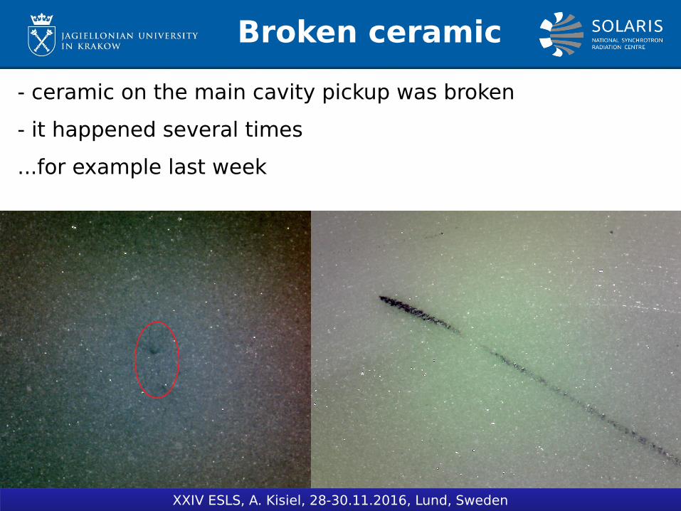
Broken ceramic
- ceramic on the main cavity pickup was broken
- it happened several times
...for example last week
XXIV ESLS, A. Kisiel, 28-30.11.2016, Lund, Sweden
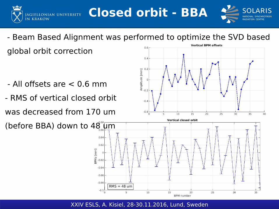
Closed orbit - BBA
- Beam Based Alignment was performed to optimize the SVD based
global orbit correction
XXIV ESLS, A. Kisiel, 28-30.11.2016, Lund, Sweden
- All offsets are < 0.6 mm
- RMS of vertical closed orbit
was decreased from 170 um
(before BBA) down to 48 um

Closed orbit - BBA
- Beam Based Alignment was performed to optimize the SVD
based global orbit correction
XXIV ESLS, A. Kisiel, 28-30.11.2016, Lund, Sweden
- All offsets are < 0.6 mm
- RMS of horizontal closed
orbit was NOT decreased
due to huge
''misalignment'' in the
centre of DBA2
What was the cause
of this problem?
DBA2 investigation
XXIV ESLS, A. Kisiel, 28-30.11.2016, Lund, Sweden
- This achromat is a prototype one and differs from
others (different manufacturing process, performance ).
- It does not seems to affect the optics, but it has some
consequences in orbit correction.
- It was corrected in software by applying fixed offset to
the BPM.
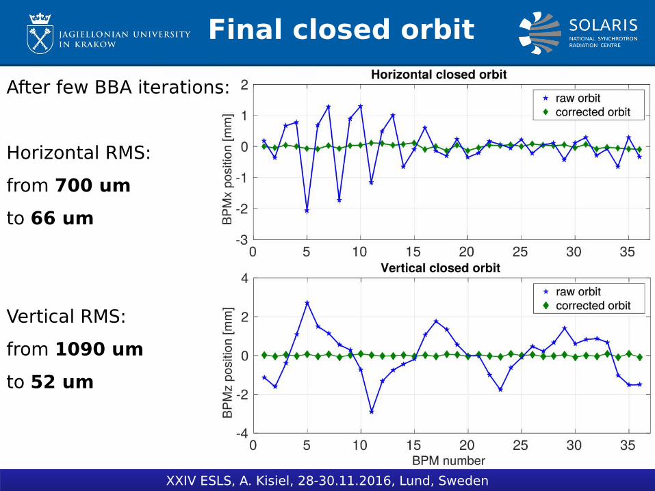
Final closed orbit
XXIV ESLS, A. Kisiel, 28-30.11.2016, Lund, Sweden
After few BBA iterations:
Horizontal RMS:
from 700 um
to 66 um
Vertical RMS:
from 1090 um
to 52 um
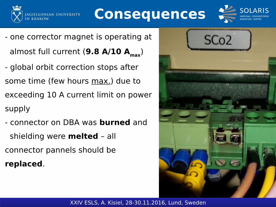
Consequences
XXIV ESLS, A. Kisiel, 28-30.11.2016, Lund, Sweden
- one corrector magnet is operating at
almost full current (9.8 A/10 Amax)
- global orbit correction stops after
some time (few hours max.) due to
exceeding 10 A current limit on power
supply
- connector on DBA was burned and
shielding were melted – all
connector pannels should be
replaced.
Other malfunction
XXIV ESLS, A. Kisiel, 28-30.11.2016, Lund, Sweden
- Shunting resistor plate had to be changed because
original design were not suitable for the power
dissipation.
- Shunting of DBA2 is needed to be reconsideren in
order to compensate the difference of this achromat
relative to others

Orbit drift
Automatic orbit correction switches off during beam decay what
causes long-term orbit drifts as presented on the picture:
XXIV ESLS, A. Kisiel, 28-30.11.2016, Lund, Sweden
Beam decay
for 36 hours:
- Horizontal
drift: ~65 um
-Vertical drift:
~27 um
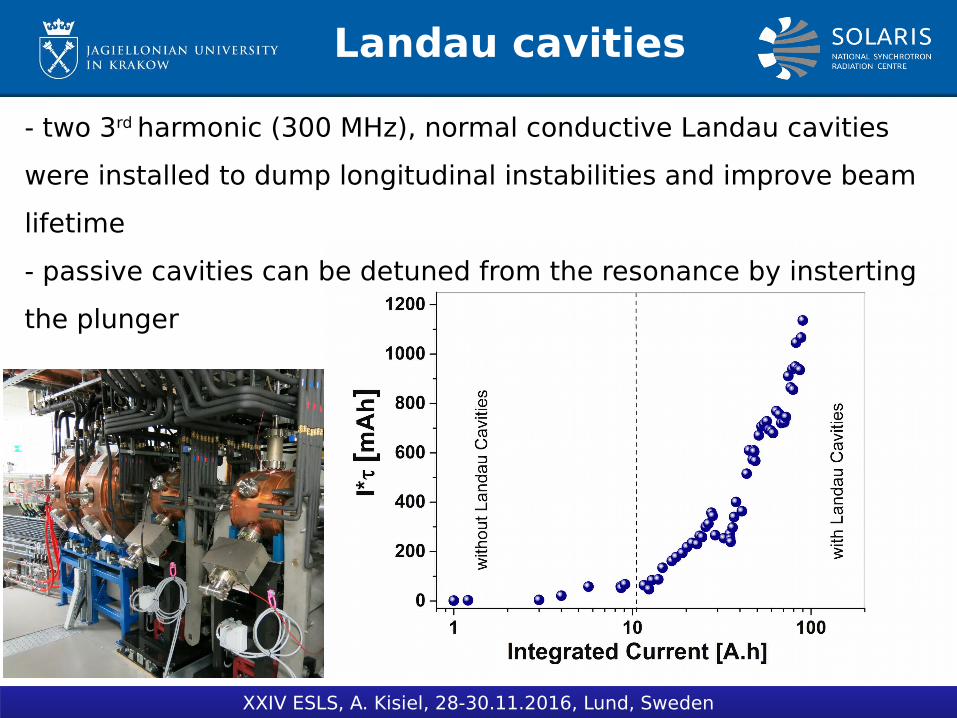
Landau cavities
XXIV ESLS, A. Kisiel, 28-30.11.2016, Lund, Sweden
- two 3rd harmonic (300 MHz), normal conductive Landau cavities
were installed to dump longitudinal instabilities and improve beam
lifetime
- passive cavities can be detuned from the resonance by insterting
the plunger
Tuning Landau cavities
XXIV ESLS, A. Kisiel, 28-30.11.2016, Lund, Sweden
- Two types of tuning mechanisms are used in Landau cavities:
endplates (slow detuning) and plunger (fast detuning).
- Plungers can be moved in the range from 0 mm (extracted) to 80
mm (inserted).
- This allows to change the frequency by 600 kHz above the
resonance.
- Now, with extracted plunger, Landaus are tuned 30-60 kHz
above the 3rd harmonics of main cavity.
- Proper Landau tuning is very difficult due to no possibility to
measure bunch length or shape (diagnostic beamline needed)
Tuning Landau cavities
XXIV ESLS, A. Kisiel, 28-30.11.2016, Lund, Sweden
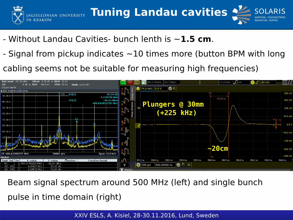
- Without Landau Cavities- bunch lenth is ~1.5 cm.
- Signal from pickup indicates ~10 times more (button BPM with long
cabling seems not be suitable for measuring high frequencies)
Beam signal spectrum around 500 MHz (left) and single bunch
pulse in time domain (right)
Tuning Landau cavities
XXIV ESLS, A. Kisiel, 28-30.11.2016, Lund, Sweden
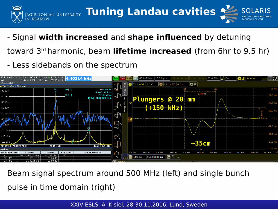
- Signal width increased and shape influenced by detuning
toward 3rd harmonic, beam lifetime increased (from 6hr to 9.5 hr)
- Less sidebands on the spectrum
Beam signal spectrum around 500 MHz (left) and single bunch
pulse in time domain (right)

Tuning Landau cavities
XXIV ESLS, A. Kisiel, 28-30.11.2016, Lund, Sweden
- Signal width increased and bunch splitted(?), beam lifetime
decreased (from optimal 9.5 hr to 7 hr)
- A lot of sidebands on the spectrum
Beam signal spectrum around 500 MHz (left) and single bunch
pulse in time domain (right)
Tuning Landau cavities
XXIV ESLS, A. Kisiel, 28-30.11.2016, Lund, Sweden
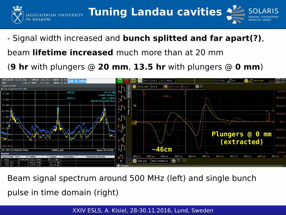
- Signal width increased and bunch splitted and far apart(?),
beam lifetime increased much more than at 20 mm
(9 hr with plungers @ 20 mm, 13.5 hr with plungers @ 0 mm)
Beam signal spectrum around 500 MHz (left) and single bunch
pulse in time domain (right)
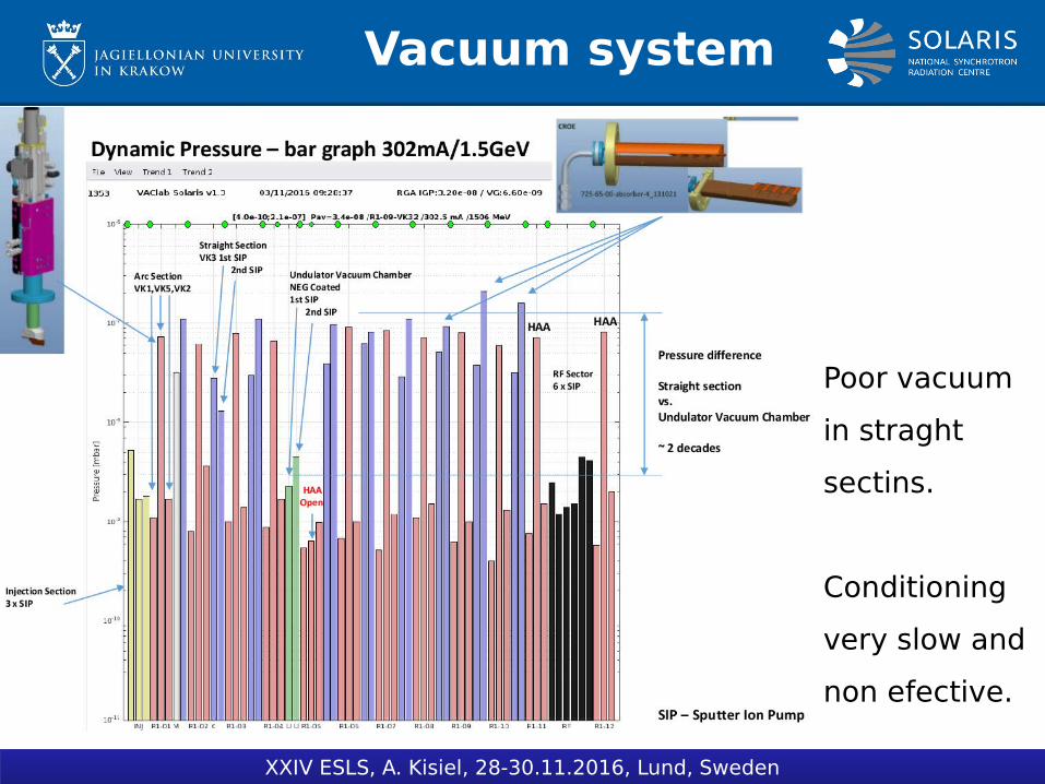
Vacuum system
XXIV ESLS, A. Kisiel, 28-30.11.2016, Lund, Sweden
Poor vacuum
in straght
sectins.
Conditioning
very slow and
non efective.
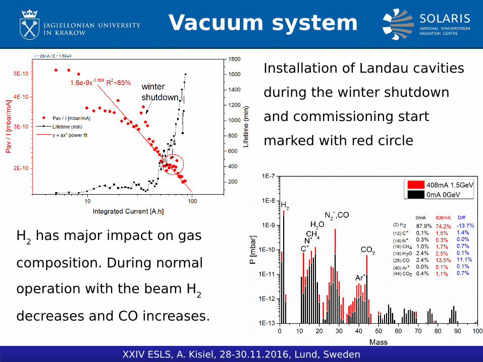
Vacuum system
XXIV ESLS, A. Kisiel, 28-30.11.2016, Lund, Sweden
H2 has major impact on gas
composition. During normal
operation with the beam H2
decreases and CO increases.
Installation of Landau cavities
during the winter shutdown
and commissioning start
marked with red circle
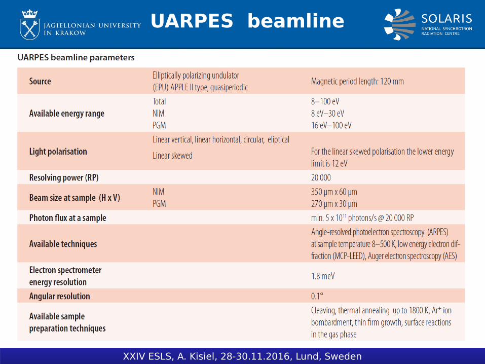
UARPES beamline
XXIV ESLS, A. Kisiel, 28-30.11.2016, Lund, Sweden

UARPES commissioning
22.04.2016 first light after first mirror!
XXIV ESLS, A. Kisiel, 28-30.11.2016, Lund, Sweden
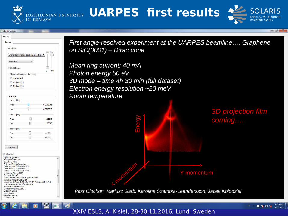
UARPES first results
XXIV ESLS, A. Kisiel, 28-30.11.2016, Lund, Sweden
First angle-resolved experiment at the UARPES beamline…. Graphene on SiC(0001) – Dirac cone
Mean ring current: 40 mAPhoton energy 50 eV3D mode – time 4h 30 min (full dataset)Electron energy resolution ~20 meV Room temperature
Piotr Ciochon, Mariusz Garb, Karolina Szamota-Leandersson, Jacek Kolodziej
Y momentum
X momentum
Ene
rgy
3D projection film coming….
Future plans1. Second beamline (PEEM/XAS) is being preapared to open for the synchrotron
radiation.
2. Next beamline PHELIX (soft X-ray beamline) was founded in May 2016 and
the construction has started – operation in 2020
3. Old MAX-Lab beamline I1011 transferred to Solaris – waiting for financial
support for installation
4. Application for money for next two beamlines (Infra red beamline and hard X-
ray beamline)
5. Start of user operation in 2017
6. Accelerator studies:
- LOCO
- Touschek lifetime
- Beam instabilities
- Dynamic aperture
7.Increasing the performance of the storage ring: much more accumulated
current, better vacuum conditions, more stable beam.
8. Installation of HOM filters
9. Machine improvements: completing the chopper, changing pickup in main
cavities to non-ceramic, diagnostic beamline, emittance measurement setup
etc.
XXIV ESLS, A. Kisiel, 28-30.11.2016, Lund, Sweden
Future plans7.Increasing the performance of the storage ring: much more accumulated
current, better vacuum conditions, more stable beam.
8. Installation of HOM filters
9. Machine improvements: completing the chopper, changing pickup in main
cavities to non-ceramic, diagnostic beamline, emittance measurement setup
etc.
XXIV ESLS, A. Kisiel, 28-30.11.2016, Lund, Sweden
Summary- After one year of commissioning a good performance of the Solaris light source has been achieved. - Injection to the storage ring occurs at 525 MeV and the beam is ramped to the operating energy of 1.5 GeV. - The injection efficiency has been improved reaching now 20% and is still under optimisation. - The maximum injected current achieved at 525 MeV has been 596 mA at the filling pattern of 2/3. - The maximum current ramped to the final energy of 1.5 GeV is above 400 mA due to poor performance of the ceramic gap in main cavity pickup.- The optics was corrected close to the design one. However some adjustments are still needed. - Next step is to calculate the linear optics from the orbit (LOCO) and optimise the beta functions with the UARPES EPU in operation. - Taking into account the closed orbit – some of the magnets need realignment, which should improve the orbit and relax the corrector strengths. - Commissioning of UARPES beamline in progress
XXIV ESLS, A. Kisiel, 28-30.11.2016, Lund, Sweden
Thank you for your attention!
XXIV ESLS, A. Kisiel, 28-30.11.2016, Lund, Sweden