status of the trasco project - kekconference.kek.jp/srf2001/pdf/ta009.pdf · 2.2 rfq design and...
TRANSCRIPT
STATUS OF THE TRASCO PROJECT*
Danilo Barni for the TRASCO-AC GroupINFN Milano, LASA, Via Fratelli Cervi 201, I-20090 Segrate (MI), Italy
AbstractWe present the status of TRASCO that is a joint
INFN/ENEA program aiming at the design and thetechnological investigation of the main components of anaccelerator driven system (ADS) for nuclear wastetransmutation. After a short overview of the maincomponents of the linac we focus on the description ofthe superconducting high energy sections. An analysis ofthe design criteria and a discussion of the chosen solutionare presented. The actual status of the R&D program andprototyping of the main components are also presented.
1 THE TRASCO INTENSE PROTONSOURCE: TRIPS
The design of the TRASCO intense proton source(TRIPS) has been completed in 1999 and the source hasbeen assembled at LNS in May 2000.
Its task consists in the production of a 35 mA dc protonbeam with a normalized emittance below 0.2 π mm mradat an operating voltage of 80 kV. The source is based onthe principle of off-resonance microwave discharge [1].
The microwave matching system is a four stepmaximally flat transformer, a system to move the coilson-line has been implemented, but mainly the efforts havebeen concentrated on the extraction system with the aimto increase the source availability and reliability, in orderto meet the requirement of a driver for an ADS system.
The choice of an off-resonance microwave dischargeion source has been motivated by the requirements ofhigh yield, high proton fraction and long-term stability.
The results obtained in August (55 mA with a protonfraction of 90%) confirmed that the TRIPS design couldbe reliably achieved. Low beam emittances has beenreached at SILHI by means of controlled gas injection [2].
Therefore the future developments to be done at LNSwill concern stability, reliability and reproducibility.
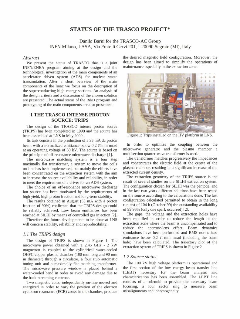
1.1 The TRIPS designThe design of TRIPS is shown in Figure 1. The
microwave power obtained with a 2.45 GHz - 2 kWmagnetron is coupled to the cylindrical water-cooledOHFC copper plasma chamber (100 mm long and 90 mmin diameter) through a circulator, a four stub automatictuning unit and a maximally flat matching transformer.The microwave pressure window is placed behind awater-cooled bend in order to avoid any damage due tothe back-streaming electrons.
Two magnetic coils, independently on-line moved andenergized in order to vary the position of the electroncyclotron resonance (ECR) zones in the chamber, produce
the desired magnetic field configuration. Moreover, thedesign has been aimed to simplify the operations ofmaintenance especially in the extraction zone.
Figure 1: Trips installed on the HV platform in LNS.
In order to optimize the coupling between themicrowave generator and the plasma chamber amultisection quarter-wave transformer is used.
The transformer matches progressively the impedancesand concentrates the electric field at the center of theplasma chamber, resulting in a significant increase of theextracted current density.
The extraction geometry of the TRIPS source is theresult of several studies on the SILHI extraction system.The configuration chosen for SILHI was the pentode, andin the last two years different solutions have been testedon the source according to the calculations done. The lastconfiguration calculated permitted to obtain in the longrun test of 104 h (October 99) the outstanding availabilityof 99.96% (only one spark occurred) [2].
The gaps, the voltage and the extraction holes havebeen modified in order to reduce the length of theextraction zone where the beam is uncompensated and toreduce the aperture-lens effect. Beam dynamicssimulations have been performed and RMS normalizedemittance below 0.2 π mm mrad (including the beamhalo) have been calculated. The trajectory plot of theextraction system of TRIPS is shown in Figure 2.
1.2 Source statusThe 100 kV high voltage platform is operational and
the first section of the low energy beam transfer line(LEBT) necessary for the beam analysis andcharacterization has been assembled. The LEBT lineconsists of a solenoid to provide the necessary beamfocusing, a four sector ring to measure beammisalignments and inhomogeneity.
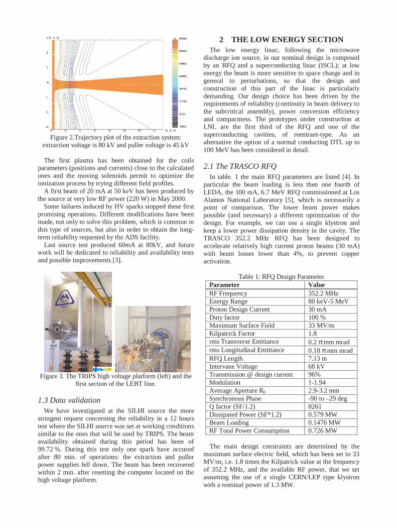
Figure 2.Trajectory plot of the extraction system:extraction voltage is 80 kV and puller voltage is 45 kV
The first plasma has been obtained for the coilsparameters (positions and currents) close to the calculatedones and the moving solenoids permit to optimize theionization process by trying different field profiles.
A first beam of 20 mA at 50 keV has been produced bythe source at very low RF power (220 W) in May 2000.
Some failures induced by HV sparks stopped these firstpromising operations. Different modifications have beenmade, not only to solve this problem, which is common inthis type of sources, but also in order to obtain the long-term reliability requested by the ADS facility.
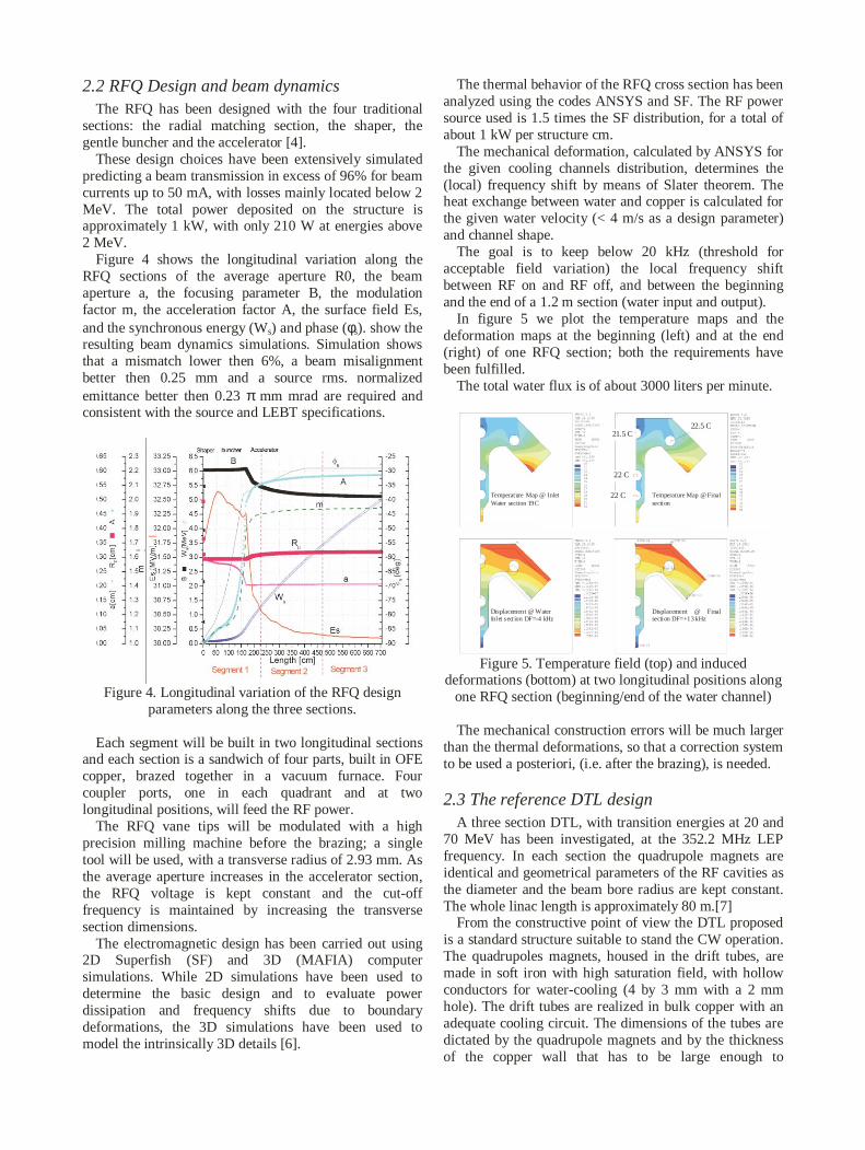
Last source test produced 60mA at 80kV, and futurework will be dedicated to reliability and availability testsand possible improvements [3].
Figure 3. The TRIPS high voltage platform (left) and thefirst section of the LEBT line.
1.3 Data validationWe have investigated at the SILHI source the more
stringent request concerning the reliability in a 12 hourstest where the SILHI source was set at working conditionssimilar to the ones that will be used by TRIPS. The beamavailability obtained during this period has been of99.72 %. During this test only one spark have occuredafter 80 min. of operations: the extraction and pullerpower supplies fell down. The beam has been recoveredwithin 2 min. after resetting the computer located on thehigh voltage platform.
2 THE LOW ENERGY SECTIONThe low energy linac, following the microwave
discharge ion source, in our nominal design is composedby an RFQ and a superconducting linac (ISCL); at lowenergy the beam is more sensitive to space charge and ingeneral to perturbations, so that the design andconstruction of this part of the linac is particularlydemanding. Our design choice has been driven by therequirements of reliability (continuity in beam delivery tothe subcritical assembly), power conversion efficiencyand compactness. The prototypes under construction atLNL are the first third of the RFQ and one of thesuperconducting cavities, of reentrant-type. As analternative the option of a normal conducting DTL up to100 MeV has been considered in detail.
2.1 The TRASCO RFQIn table. 1 the main RFQ parameters are listed [4]. In
particular the beam loading is less then one fourth ofLEDA, the 100 mA, 6.7 MeV RFQ commissioned at LosAlamos National Laboratory [5], which is necessarily apoint of comparison. The lower beam power makespossible (and necessary) a different optimization of thedesign. For example, we can use a single klystron andkeep a lower power dissipation density in the cavity. TheTRASCO 352.2 MHz RFQ has been designed toaccelerate relatively high current proton beams (30 mA)with beam losses lower than 4%, to prevent copperactivation.
Table 1: RFQ Design ParameterParameter ValueRF Frequency 352.2 MHzEnergy Range 80 keV-5 MeVProton Design Current 30 mADuty factor 100 %Maximum Surface Field 33 MV/mKilpatrick Factor 1.8rms Transverse Emittance 0.2 πmm mradrms Longitudinal Emittance 0.18 πmm mradRFQ Length 7.13 mIntervane Voltage 68 kVTransmission @ design current 96%Modulation 1-1.94Average Aperture R0 2.9-3.2 mmSynchronous Phase -90 to –29 degQ factor (SF/1.2) 8261Dissipated Power (SF*1.2) 0.579 MWBeam Loading 0.1476 MWRF Total Power Consumption 0.726 MW
The main design constraints are determined by themaximum surface electric field, which has been set to 33MV/m, i.e. 1.8 times the Kilpatrick value at the frequencyof 352.2 MHz, and the available RF power, that we setassuming the use of a single CERN/LEP type klystronwith a nominal power of 1.3 MW.
2.2 RFQ Design and beam dynamicsThe RFQ has been designed with the four traditional
sections: the radial matching section, the shaper, thegentle buncher and the accelerator [4].
These design choices have been extensively simulatedpredicting a beam transmission in excess of 96% for beamcurrents up to 50 mA, with losses mainly located below 2MeV. The total power deposited on the structure isapproximately 1 kW, with only 210 W at energies above2 MeV.
Figure 4 shows the longitudinal variation along theRFQ sections of the average aperture R0, the beamaperture a, the focusing parameter B, the modulationfactor m, the acceleration factor A, the surface field Es,and the synchronous energy (Ws) and phase (φs). show theresulting beam dynamics simulations. Simulation showsthat a mismatch lower then 6%, a beam misalignmentbetter then 0.25 mm and a source rms. normalizedemittance better then 0.23 π mm mrad are required andconsistent with the source and LEBT specifications.
Figure 4. Longitudinal variation of the RFQ designparameters along the three sections.
Each segment will be built in two longitudinal sectionsand each section is a sandwich of four parts, built in OFEcopper, brazed together in a vacuum furnace. Fourcoupler ports, one in each quadrant and at twolongitudinal positions, will feed the RF power.
The RFQ vane tips will be modulated with a highprecision milling machine before the brazing; a singletool will be used, with a transverse radius of 2.93 mm. Asthe average aperture increases in the accelerator section,the RFQ voltage is kept constant and the cut-offfrequency is maintained by increasing the transversesection dimensions.
The electromagnetic design has been carried out using2D Superfish (SF) and 3D (MAFIA) computersimulations. While 2D simulations have been used todetermine the basic design and to evaluate powerdissipation and frequency shifts due to boundarydeformations, the 3D simulations have been used tomodel the intrinsically 3D details [6].
The thermal behavior of the RFQ cross section has beenanalyzed using the codes ANSYS and SF. The RF powersource used is 1.5 times the SF distribution, for a total ofabout 1 kW per structure cm.
The mechanical deformation, calculated by ANSYS forthe given cooling channels distribution, determines the(local) frequency shift by means of Slater theorem. Theheat exchange between water and copper is calculated forthe given water velocity (< 4 m/s as a design parameter)and channel shape.
The goal is to keep below 20 kHz (threshold foracceptable field variation) the local frequency shiftbetween RF on and RF off, and between the beginningand the end of a 1.2 m section (water input and output).
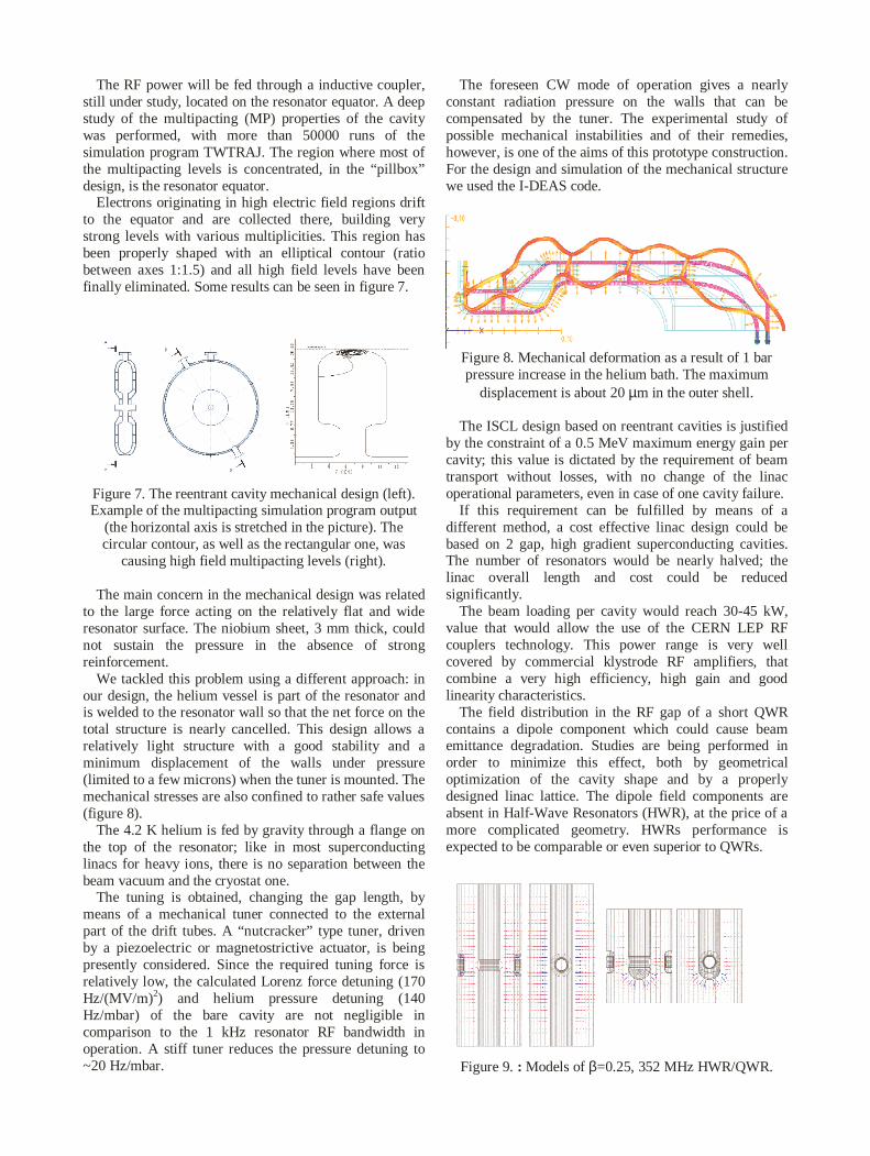
In figure 5 we plot the temperature maps and thedeformation maps at the beginning (left) and at the end(right) of one RFQ section; both the requirements havebeen fulfilled.
The total water flux is of about 3000 liters per minute.
Temperature Map @ InletWater section 19C
Temperature Map @ Finalsection
Displacement @ WaterInlet sect ion DF=-4 kHz
Displacement @ Finalsection DF=+13 kHz
21.5 C
22 C
22 C
22.5 C
Figure 5. Temperature field (top) and induceddeformations (bottom) at two longitudinal positions along
one RFQ section (beginning/end of the water channel)
The mechanical construction errors will be much largerthan the thermal deformations, so that a correction systemto be used a posteriori, (i.e. after the brazing), is needed.
2.3 The reference DTL designA three section DTL, with transition energies at 20 and
70 MeV has been investigated, at the 352.2 MHz LEPfrequency. In each section the quadrupole magnets areidentical and geometrical parameters of the RF cavities asthe diameter and the beam bore radius are kept constant.The whole linac length is approximately 80 m.[7]
From the constructive point of view the DTL proposedis a standard structure suitable to stand the CW operation.The quadrupoles magnets, housed in the drift tubes, aremade in soft iron with high saturation field, with hollowconductors for water-cooling (4 by 3 mm with a 2 mmhole). The drift tubes are realized in bulk copper with anadequate cooling circuit. The dimensions of the tubes aredictated by the quadrupole magnets and by the thicknessof the copper wall that has to be large enough to

efficiently transmit the heat generated by the RFdissipation to the cooling circuit. The drift tubedimensions and shape are critical for obtaining a highshunt impedance.
The beam dynamics was simulated with PARMILAcode and the DTL aperture is always between 8 and 12times the beam rms radius, a safe value at these energies.
Due to the low shunt impedance value of the RFstructures a 100 MeV, 30 mA linac dissipatesapproximately 9 MW in the structure, a considerableamount of power that, at these moderate currents, has anon-negligible impact on the whole linac efficiency.
2.4 The superconducting ISCLA superconducting option for the 5-100 MeV linac is
also under study. We considered an Independently phasedSuperconducting Cavity Linac (ISCL) similar to thoseused for low energy heavy ions in many nuclear physicslaboratories like ours, but at much higher beam intensity,and in a wider beta range. We checked various kind ofcavities and we selected the so-called “reentrant cavities”,that are modified pillbox, cylindrically symmetric andtherefore theoretically dipole free [8].
One of the advantages of this kind of linac is itsflexibility, that allows using it CW at lower current oreven with different kind of particles, like deuterons. Intable 2 we list the main specifications and machinecharacteristics. In particular we specified the two mainconstraints of the independently phased resonators: thesurface field and the beam loading per cavity. The secondconstraint is specific of high current machines: in our casewe want to feed each cavity with a single solid stateamplifier and the limitation to 15 kW is consistent withthe present technology.
Table 2.ISCL Design Parameters.Parameter ValueEnergy range 5-100MeVTotal length 48 mSynchronous phase -40Average acceleration 1.82 degNumber of cavities 230Cavity bore radius 1.5 cmQuadrupole gradient 31 T/mQuad aperture/length 2/5 cm
Trans. 0.42 mm mradOutputRMS Emittance Long. 0.2 mm mradCurrent limit (losses<10-4) >50 mARF dissipation(Rs=100 nΩ, RBCS=58 nΩ)
1204 W(@4.2K)
Beam loading 2.85 MWRF sys. pwr. cons. (ηRF=50%) 5.7 WStatic cryogenic losses (10 W/m) 480 WCryo. Consumption (ηcryo=1/500) 0.84 MWQuadrupoles and ancillaries 0.5 MWMains power 7.04 MWPower conversion efficiency 40 %
An additional constraint is given by the reliabilityrequirements typical of an ADS, where the operation witha sub-critical reactor is spoiled even by a beam shut downof a second. To meet these requirements we have chosenan architecture with reliable solid state amplifiers. Even inthe presence of a large number of such RF systems withfinite reliability, we required that the beam could betransmitted in case of failure of a cavity. This isconnected to the requirement that the acceleration percavity plus the energy spread is smaller than theseparatrix energy width. If the beam survives the failureof a single amplifier, and the amplifier can be replaced online, the resulting availability of the linac is highlyimproved.
We have chosen a FODO focusing structure withperiod 8 βλ. As the period becomes longer, a largernumber of cavities can be installed between thequadrupoles (figure 6).
Figure 6. ISCL layout: reentrant cavities and quadrupolesin the cyrostat.
The cavity geometry has been analyzed with theSUPERFISH code, and the main parameters are reportedin Table 3 [9]. Since the performances of the reentrantcavities have been limited in the past by the strongmultipacting behavior of the pillbox shape with a flattopequator, the cavity shape has been modified with anelliptical equator shape, in order to lower the field levelsin the equatorial region.
Table 3 Resonator parameters calculated by means of thecode SUPERFISH.
Parameter Value UnitsTotal length 135 mmInternal length 80 mmBore radius 15 mmFrequency 352.2 MHzU/Ea
2 0.034 J/(MV/m)2Ep/Ea 3.05Hp/Ea 30.6 G/(MV/m)Γ=Rs×Q 83.9 ΩRsh (Cu) 18 MΩ/mβ ≥ 0.1
Since the main limitation in low-β superconductingcavities is usually determined by the maximumachievable surface electric field, related to the onset offield emission, and since our linac design requiredrelatively low energy gain per cavity, we looked mainlyfor low surface electric and magnetic field, and shortphysical dimensions.
The RF power will be fed through a inductive coupler,still under study, located on the resonator equator. A deepstudy of the multipacting (MP) properties of the cavitywas performed, with more than 50000 runs of thesimulation program TWTRAJ. The region where most ofthe multipacting levels is concentrated, in the “pillbox”design, is the resonator equator.
Electrons originating in high electric field regions driftto the equator and are collected there, building verystrong levels with various multiplicities. This region hasbeen properly shaped with an elliptical contour (ratiobetween axes 1:1.5) and all high field levels have beenfinally eliminated. Some results can be seen in figure 7.
Figure 7. The reentrant cavity mechanical design (left).Example of the multipacting simulation program output
(the horizontal axis is stretched in the picture). Thecircular contour, as well as the rectangular one, was
causing high field multipacting levels (right).
The main concern in the mechanical design was relatedto the large force acting on the relatively flat and wideresonator surface. The niobium sheet, 3 mm thick, couldnot sustain the pressure in the absence of strongreinforcement.
We tackled this problem using a different approach: inour design, the helium vessel is part of the resonator andis welded to the resonator wall so that the net force on thetotal structure is nearly cancelled. This design allows arelatively light structure with a good stability and aminimum displacement of the walls under pressure(limited to a few microns) when the tuner is mounted. Themechanical stresses are also confined to rather safe values(figure 8).
The 4.2 K helium is fed by gravity through a flange onthe top of the resonator; like in most superconductinglinacs for heavy ions, there is no separation between thebeam vacuum and the cryostat one.
The tuning is obtained, changing the gap length, bymeans of a mechanical tuner connected to the externalpart of the drift tubes. A “nutcracker” type tuner, drivenby a piezoelectric or magnetostrictive actuator, is beingpresently considered. Since the required tuning force isrelatively low, the calculated Lorenz force detuning (170Hz/(MV/m)2) and helium pressure detuning (140Hz/mbar) of the bare cavity are not negligible incomparison to the 1 kHz resonator RF bandwidth inoperation. A stiff tuner reduces the pressure detuning to~20 Hz/mbar.
The foreseen CW mode of operation gives a nearlyconstant radiation pressure on the walls that can becompensated by the tuner. The experimental study ofpossible mechanical instabilities and of their remedies,however, is one of the aims of this prototype construction.For the design and simulation of the mechanical structurewe used the I-DEAS code.
Figure 8. Mechanical deformation as a result of 1 barpressure increase in the helium bath. The maximum
displacement is about 20 µm in the outer shell.
The ISCL design based on reentrant cavities is justifiedby the constraint of a 0.5 MeV maximum energy gain percavity; this value is dictated by the requirement of beamtransport without losses, with no change of the linacoperational parameters, even in case of one cavity failure.
If this requirement can be fulfilled by means of adifferent method, a cost effective linac design could bebased on 2 gap, high gradient superconducting cavities.The number of resonators would be nearly halved; thelinac overall length and cost could be reducedsignificantly.
The beam loading per cavity would reach 30-45 kW,value that would allow the use of the CERN LEP RFcouplers technology. This power range is very wellcovered by commercial klystrode RF amplifiers, thatcombine a very high efficiency, high gain and goodlinearity characteristics.
The field distribution in the RF gap of a short QWRcontains a dipole component which could cause beamemittance degradation. Studies are being performed inorder to minimize this effect, both by geometricaloptimization of the cavity shape and by a properlydesigned linac lattice. The dipole field components areabsent in Half-Wave Resonators (HWR), at the price of amore complicated geometry. HWRs performance isexpected to be comparable or even superior to QWRs.
Figure 9. : Models of β=0.25, 352 MHz HWR/QWR.

A specific research activity has been devoted to theinvestigation of the beam halo formation process Theusual approach to the problem is based on multiparticleprograms and particle core model (PCM). In the first caseone solves the self-consistent problem of the evolution ofthe whole particle distribution, but the number of particlesis limited by computer capabilities. In the second case onesimulates of the dynamics of test particles in the presenceof a given particle distribution; in this way the diffusionof few particles, which does not affect the beam core, canbe studied.
We have considered both directions by developing a 3Dparticle in cell program to solve the Poisson-Vlasovequation and a 3D PCM where the phase space analysis isperformed using the frequency map technique [10].
In the next year the FMA and the 3D PIC program willbe integrated in a linac design code, able to study both theemittance exchanges and the low probability particlediffusion. Recently, a very fast damping of beamenvelope oscillation amplitudes has been observed insimulations of very high intensity beams transportation(initial Gaussian distribution for σ/σ0=0.29) [11].
Several simulations, with the modified multiparticlecode PARMT, have been carried out, to point out inwhich conditions this fast damping occurs and what kindof mechanism could be responsible for it. The explanationfound involves the so called Landau damping, i.e. theattenuation of coherent oscillations when the singleparticle frequencies have a spread.
3 THE SUPERCONDUCTING HIGHENERGY LINAC
The starting energy of the high-energy superconductinglinac has been set in the 90-100 MeV energy range. Atenergies below this range the decrease in length of theelliptical cavities, and the corresponding decrease inoverall performances, favors the choice of either astandard normal conducting accelerating structure or theuse of different resonant structure geometries.
3.1 The choice of frequencyThe original choice of the 352.2 MHz frequency [12]
was motivated by a scenario in which a demonstratorADS facility was decided to be built as soon as possible(as initially proposed by Carlo Rubbia for the EnergyAmplifier/ADS demonstator). At this frequency, in fact,all the required technologies have been proven by theCERN LEP experience, and most of the necessaryancillaries exist with specifications close to the ADSrequirements [13]
During the last two years it became clear that theenvisaged time scale needed for an ADS demonstrationplant will be longer than initially expected, and the bulkniobium superconducting RF technology set by theTESLA/TTF International Collaboration [14] allows thedesign of better performing cavities with respect to theCERN sputtered technology, that dates back more than adecade.
Doubling the RF frequency to 704.4 MHz, and usingthe know-how gained by the TTF Collaboration for thedevelopment of the missing ancillary components at thesefrequencies, the superconducting linac length can benearly halved, using the possibility of operating reliably atalmost double accelerating gradients with bulk Nbcavities. The additional complication of operating at 2 Kis overcome by this drastic reduction in linac length.
One of the advantages of the 704.4 MHz frequency isthat the cavities are 8 times smaller in volume withrespect to the CERN cavities, and several infrastructuresfor cavity fabrication, treatment and measure exist(notably CEA/Saclay) or are being set up (as in INFNMilano/LASA) in Europe. These smaller cavities alsoshow a better mechanical stability (again related to thesmaller physical dimensions).
We may conclude that the 704.4 MHz choice leavesmore space for making use of the technologicalimprovements obtained in the past years by theTESLA/TFF International Collaboration, as it has beensuccessfully proven by both the single cell β=0.65cavities developed by CEA/Saclay and the single-cellβ=0.5 cavity that we have built for TRASCO.
3.2 Technological activities for the cavityproduction
Two parallel experimental activities have beenfollowed in order to assess the feasibility of bothfrequency options. The first activity, in collaboration withCERN, aimed at reaching the same LEP cavityperformances with a β=0.85 sputtered cavity, the otheraimed at proving the reliability of the bulk Nb technologyfor the low β=0.5 cavities.
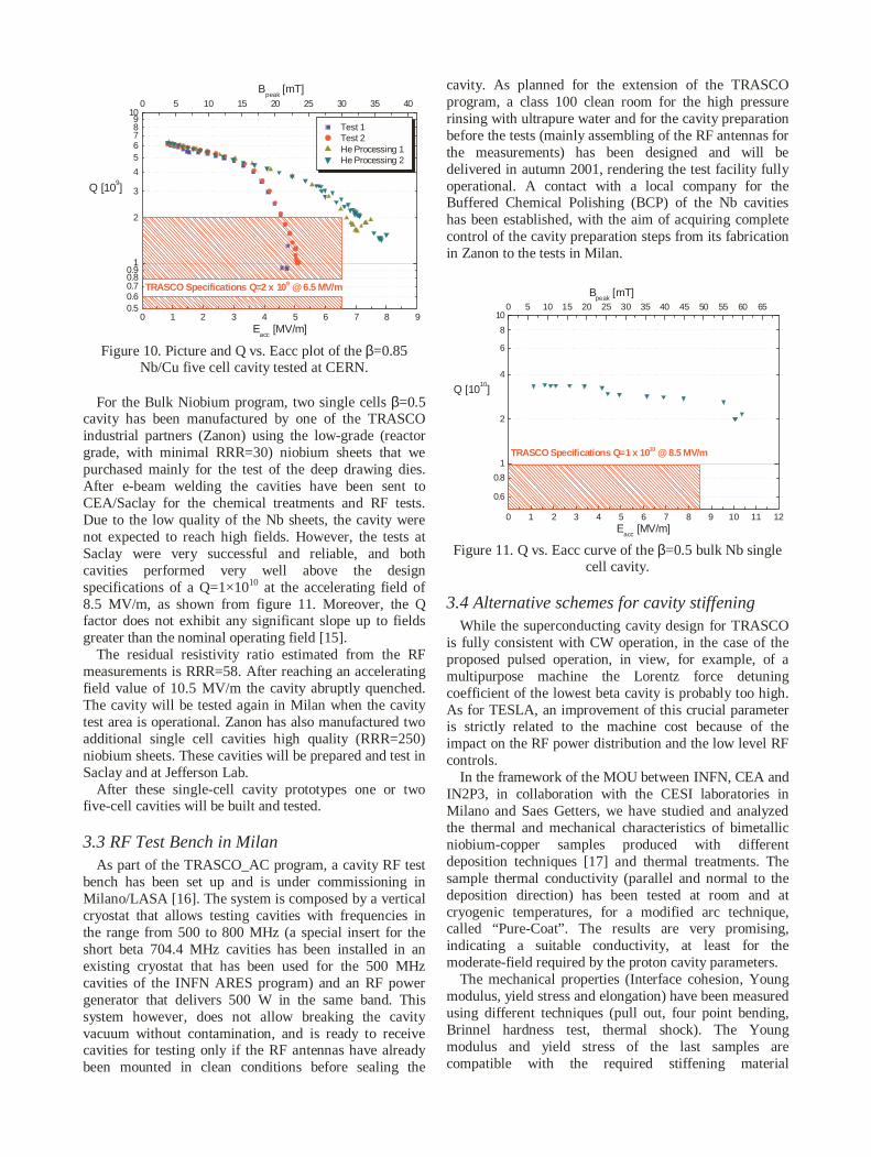
For the Cu-Nb sputtered program, one single cell andone five cell β=0.85 cavity have been built and tested byCERN with the TRASCO design at 352.2 MHz, withresults exceeding the design specifications. The results fortwo series of tests of the five-cell cavity, before and afterHe processing, are shown in figure 10. The upperhorizontal axis shows the peak magnetic field on thesurface (directly proportional to the Eacc). The ratio ofthe peak surface fields with respect to the acceleratingfield depends entirely on the cavity geometry and ishigher for lower β cavities than for electron (β=1)cavities, like the LEP II cavities. Taking into account thisfact the Q vs. Bpeak curve of the TRASCO β=0.85 cavitymeasurement falls entirely in the production spread of thelast LEP II cavities batch. The dashed area in the figureindicated the operating region of the cavities, with adesign value of Q=2×10⁹ at the accelerating field of6.5 MV/m.
An ongoing extension of the agreement with CERNallowed us to equip the cavity with a He tank, thestandard LEP tuner, coupler and HOM, install it in aspecially modified spare cryomodule, and test it in theLEP cryomodule test bench.
0 1 2 3 4 5 6 7 8 90.50.60.70.80.9
1
2
3
4
56789
10
TRASCO Specifications Q=2 x 10⁹ @6.5 MV/m
Bpeak
[mT]
Test 1Test 2He Processing 1He Processing 2
Q [109]
Eacc
[MV/m]
0 5 10 15 20 25 30 35 40
Figure 10. Picture and Q vs. Eacc plot of the β=0.85Nb/Cu five cell cavity tested at CERN.
For the Bulk Niobium program, two single cells β=0.5cavity has been manufactured by one of the TRASCOindustrial partners (Zanon) using the low-grade (reactorgrade, with minimal RRR=30) niobium sheets that wepurchased mainly for the test of the deep drawing dies.After e-beam welding the cavities have been sent toCEA/Saclay for the chemical treatments and RF tests.Due to the low quality of the Nb sheets, the cavity werenot expected to reach high fields. However, the tests atSaclay were very successful and reliable, and bothcavities performed very well above the designspecifications of a Q=1×10¹⁰ at the accelerating field of8.5 MV/m, as shown from figure 11. Moreover, the Qfactor does not exhibit any significant slope up to fieldsgreater than the nominal operating field [15].
The residual resistivity ratio estimated from the RFmeasurements is RRR=58. After reaching an acceleratingfield value of 10.5 MV/m the cavity abruptly quenched.The cavity will be tested again in Milan when the cavitytest area is operational. Zanon has also manufactured twoadditional single cell cavities high quality (RRR=250)niobium sheets. These cavities will be prepared and test inSaclay and at Jefferson Lab.
After these single-cell cavity prototypes one or twofive-cell cavities will be built and tested.
3.3 RF Test Bench in MilanAs part of the TRASCO_AC program, a cavity RF test
bench has been set up and is under commissioning inMilano/LASA [16]. The system is composed by a verticalcryostat that allows testing cavities with frequencies inthe range from 500 to 800 MHz (a special insert for theshort beta 704.4 MHz cavities has been installed in anexisting cryostat that has been used for the 500 MHzcavities of the INFN ARES program) and an RF powergenerator that delivers 500 W in the same band. Thissystem however, does not allow breaking the cavityvacuum without contamination, and is ready to receivecavities for testing only if the RF antennas have alreadybeen mounted in clean conditions before sealing the
cavity. As planned for the extension of the TRASCOprogram, a class 100 clean room for the high pressurerinsing with ultrapure water and for the cavity preparationbefore the tests (mainly assembling of the RF antennas forthe measurements) has been designed and will bedelivered in autumn 2001, rendering the test facility fullyoperational. A contact with a local company for theBuffered Chemical Polishing (BCP) of the Nb cavitieshas been established, with the aim of acquiring completecontrol of the cavity preparation steps from its fabricationin Zanon to the tests in Milan.
0 1 2 3 4 5 6 7 8 9 10 11 12
0.6
0.8
1
2
4
6
8
10
TRASCO Specifications Q=1 x 10¹⁰ @ 8.5 MV/m
Bpeak
[mT]
Q [1010
]
Eacc
[MV/m]
0 5 10 15 20 25 30 35 40 45 50 55 60 65
Figure 11. Q vs. Eacc curve of the β=0.5 bulk Nb singlecell cavity.
3.4 Alternative schemes for cavity stiffeningWhile the superconducting cavity design for TRASCO
is fully consistent with CW operation, in the case of theproposed pulsed operation, in view, for example, of amultipurpose machine the Lorentz force detuningcoefficient of the lowest beta cavity is probably too high.As for TESLA, an improvement of this crucial parameteris strictly related to the machine cost because of theimpact on the RF power distribution and the low level RFcontrols.
In the framework of the MOU between INFN, CEA andIN2P3, in collaboration with the CESI laboratories inMilano and Saes Getters, we have studied and analyzedthe thermal and mechanical characteristics of bimetallicniobium-copper samples produced with differentdeposition techniques [17] and thermal treatments. Thesample thermal conductivity (parallel and normal to thedeposition direction) has been tested at room and atcryogenic temperatures, for a modified arc technique,called “Pure-Coat”. The results are very promising,indicating a suitable conductivity, at least for themoderate-field required by the proton cavity parameters.
The mechanical properties (Interface cohesion, Youngmodulus, yield stress and elongation) have been measuredusing different techniques (pull out, four point bending,Brinnel hardness test, thermal shock). The Youngmodulus and yield stress of the last samples arecompatible with the required stiffening material
specifications. The initial problem of an extremebrittleness of the deposited copper, showing an elongationbefore rupture of less than 0.2%, is being solved througha well-calibrated heat treatment under vacuum. A value of2% has already been measured on the treated samples.
The technological analyses are crosschecked withphysical tests (SEM, Auger and XPS), to obtain acorrelation between the material structure, its compositionand the physical behavior. The results of the analysis arefed back for the optimization of the deposition proceduresand of the surface treatments.
3.5 Conceptual design of the TRASCOCryomodules
The design of the cryomodule [18] needs to be basedmainly on the ADS requirements in terms of reliabilityand system engineering.
The cryomodule reliability is dominated by the vacuum(insulation, coupler and beam) system and by the heliumcooling distribution. Fast access to the module and easyrepairing, during maintenance time, complete therequirements. To achieve these requirements thecryomodules we are designing are completelyindependent from each other. The cryogenic transfer lineruns along the modules string and the connection boxeslink the modules to the He supply. Vacuum ports and RFdistribution have also their own connections. Eachcryomodule can be physically separated from the linewith no perturbation on the working condition of theothers.
To ensure good RF cavity performances the cavitiesneed to be completely assembled in good cleaningcondition (at least class 100 clean room) and all theconnections to external ports have to be closed in theclean room.
The power coupler is another critical component thatneeds to be completely assembled and closed in the cleanroom. These constraints result in the necessity ofconsiderable clearance space to fix the cold mass (that isthe cavity string with the couplers and the thermalshields) in the vacuum vessel. The operation has also toprevent the alignments.
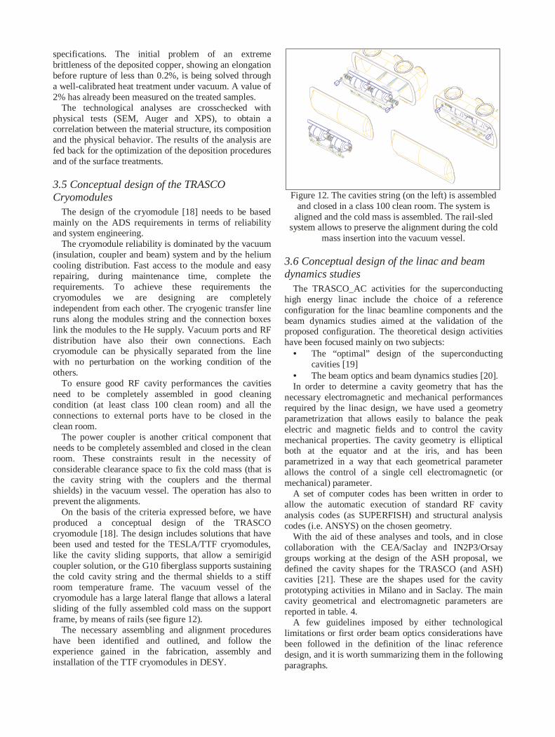
On the basis of the criteria expressed before, we haveproduced a conceptual design of the TRASCOcryomodule [18]. The design includes solutions that havebeen used and tested for the TESLA/TTF cryomodules,like the cavity sliding supports, that allow a semirigidcoupler solution, or the G10 fiberglass supports sustainingthe cold cavity string and the thermal shields to a stiffroom temperature frame. The vacuum vessel of thecryomodule has a large lateral flange that allows a lateralsliding of the fully assembled cold mass on the supportframe, by means of rails (see figure 12).
The necessary assembling and alignment procedureshave been identified and outlined, and follow theexperience gained in the fabrication, assembly andinstallation of the TTF cryomodules in DESY.
I-DEAS Student Edition : Design
Figure 12. The cavities string (on the left) is assembledand closed in a class 100 clean room. The system is
aligned and the cold mass is assembled. The rail-sledsystem allows to preserve the alignment during the cold
mass insertion into the vacuum vessel.
3.6 Conceptual design of the linac and beamdynamics studies
The TRASCO_AC activities for the superconductinghigh energy linac include the choice of a referenceconfiguration for the linac beamline components and thebeam dynamics studies aimed at the validation of theproposed configuration. The theoretical design activitieshave been focused mainly on two subjects:
• The “optimal” design of the superconductingcavities [19]
• The beam optics and beam dynamics studies [20].In order to determine a cavity geometry that has the
necessary electromagnetic and mechanical performancesrequired by the linac design, we have used a geometryparametrization that allows easily to balance the peakelectric and magnetic fields and to control the cavitymechanical properties. The cavity geometry is ellipticalboth at the equator and at the iris, and has beenparametrized in a way that each geometrical parameterallows the control of a single cell electromagnetic (ormechanical) parameter.
A set of computer codes has been written in order toallow the automatic execution of standard RF cavityanalysis codes (as SUPERFISH) and structural analysiscodes (i.e. ANSYS) on the chosen geometry.
With the aid of these analyses and tools, and in closecollaboration with the CEA/Saclay and IN2P3/Orsaygroups working at the design of the ASH proposal, wedefined the cavity shapes for the TRASCO (and ASH)cavities [21]. These are the shapes used for the cavityprototyping activities in Milano and in Saclay. The maincavity geometrical and electromagnetic parameters arereported in table. 4.
A few guidelines imposed by either technologicallimitations or first order beam optics considerations havebeen followed in the definition of the linac referencedesign, and it is worth summarizing them in the followingparagraphs.

Table. 4: Main cavity parameters.Geometrical ParametersSynchronous beta 0.50 0.68 0.86Number of cells 5 5 6Cell. Length [mm] 100 140 180Geometrical beta 0.470 0.658 0.846Full Length [mm] 900 1100 1480Iris diameter [mm] 80 90 100Coupler Tube ∅ [mm] 130Internal wall angle,[°] 5.5 8.5 8.5Equator ellipse ratio, R 1.6 1 1Iris ellipse ratio, r 1.3 1.3 1.4Full cavity electromagnetic ParametersMax. Epeak/Eacc 3.59 2.61 2.36Max. Bpeak/Eacc 5.87 4.88 4.08Cell coupling [%] 1.34 1.10 1.28R/Q [Ohm] 159 315 598
The energy range from about 90-100 MeV up to 1-2GeV can be efficiently covered with three sections, i.e.with three different cavity types. A larger number ofsections would imply a wider cavity R&D activity for asmaller number of production cavities, while a smallerone would lead to inefficient use of the cavity transit timefactor.
The transition energies between the sections have been(loosely) set to 200 MeV and 500 MeV, independently onthe optimization of the input energy (say from 85 to 100MeV) and from the output energy (from 1 to 2 GeV).
The number of cavities per section has been derivedusing a conservative value of 50 mT for the peak surfacemagnetic field. The number of cells has been chosen to be5 in the two lowest beta sections and 6 in the highest betasection.
The transverse focusing lattice is formed by an array ofquadrupole doublets, with the cavity cryostats in the longdrift between quads. The cryostats contain 2 cavities inthe two lowest beta sections and 4 cavities in the highestbeta. With these choices the doublet periodicity in thethree sections is 4.2, 4.6 and 8.5 m, respectively, and thequadrupole doublets are located in a 1.6 m warm sectionbetween the cryomodules. Table. 5 lists the mainparameters of the linac sections for the 1 GeV and the 2GeV linac cases.
The beam line design and matching has beeninvestigated and analyzed with a number of differentbeam optics codes, either standard design codes availablein the accelerator community or tools that have beendeveloped for the proton linac studies in Milano or Saclay[15]. These codes allowed to set the desired transversephase advances law, and the matching conditions at thelinac entrance, and between the linac sections, that areneeded to minimize the emittance growth that can lead toundesired beam losses.
We have specially written a beam dynamics code46)for the simulations of the SC TRASCO linac (SCDyn),which advances particles in phase steps through the beamline elements of the linac.
Table 5 : Main SC linac section parameters.# 3# 1 # 2
1-2 GeVSection βs 0.50 0.68 0.86
Section Length [m] 84 124.2 110.5-297.5Input Energy [MeV] 85 200 500Focussing Period [m] 4.2 4.6 8.5# Focussing Periods 20 27 13-35Max Gain/Cav [MeV] 3.3 6.0 11.4Max Eacc [MV/m] 8.5 10.2 12.3# Cells/Cavity 5 5 6# Cav/Section 40 54 52-140# Cav/Cryomodule 2 2 4# Module/Klystron 1 1 1Max RFCoupler [kW] 66 120 228
The space charge calculations in SCDyn are performedwith a cloud in cell charge deposition scheme and a 3DV-cycle multigrid Poisson solver in the beam rest frame.We have extensively used SCDyn for the validation of theTRASCO linac design, and made comparisons with otherbeam dynamics codes, notably Parmila (Los Alamos) andPartran (Saclay). In figure. 13 we show the behavior ofthe rms beam sizes along the beam line, for a 1 GeV linaccase, corresponding to the same matched case of theprevious figure. The beam sizes shown in the figure arethe rms envelopes evaluated from the SCDynmultiparticle simulations.
0 50 100 150 200 250 300-5
-4
-3
-2
-1
0
1
2
3
4
5
Tra
nsve
rse
rms
beam
size
s[m
m]
Position along the linac [m]
σx
[mm]σ
y[mm]
σz
[deg]
-5
-4
-3
-2
-1
0
1
2
3
4
5
Long
itudi
nalr
ms
beam
size
[deg
]
Figure. 13: rms matched beamsizes in the 1 GeV linac,from the SCDyn simulations.
Finally, figure 14 shows the phase spaces of the outputbeam from the SCDyn simulations, at 1 GeV, for a 50,000particles simulation. The two ellipses drawn on the phasespaces indicate the rms emittance and 4 times the rms.The characteristics rectangular shape of a space chargedominated beam can be clearly seen in the horizontalphase space (top left). Mismatched case up to a mismatchfactor of 30% have shown the onset of filamentationeffects that increase the beam emittances, but no evidenceof unbounded orbits (that result in beam halos) could beseen from the simulations.
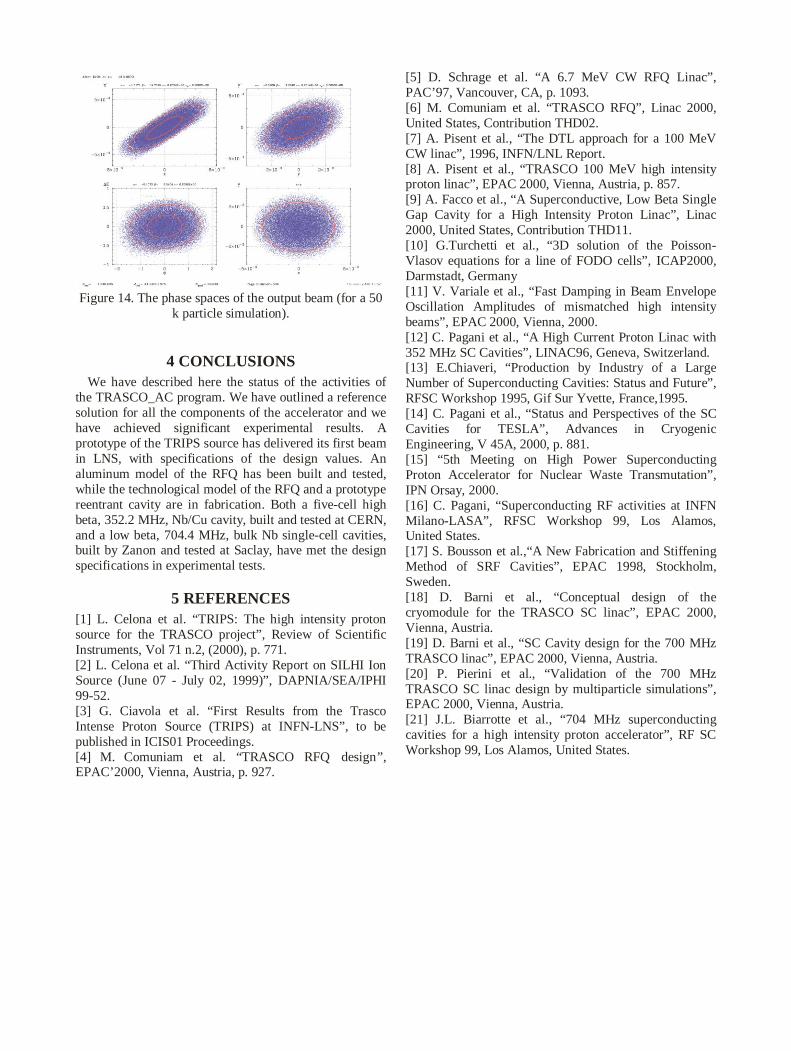
Figure 14. The phase spaces of the output beam (for a 50k particle simulation).
4 CONCLUSIONSWe have described here the status of the activities of
the TRASCO_AC program. We have outlined a referencesolution for all the components of the accelerator and wehave achieved significant experimental results. Aprototype of the TRIPS source has delivered its first beamin LNS, with specifications of the design values. Analuminum model of the RFQ has been built and tested,while the technological model of the RFQ and a prototypereentrant cavity are in fabrication. Both a five-cell highbeta, 352.2 MHz, Nb/Cu cavity, built and tested at CERN,and a low beta, 704.4 MHz, bulk Nb single-cell cavities,built by Zanon and tested at Saclay, have met the designspecifications in experimental tests.
5 REFERENCES[1] L. Celona et al. “TRIPS: The high intensity protonsource for the TRASCO project”, Review of ScientificInstruments, Vol 71 n.2, (2000), p. 771.[2] L. Celona et al. “Third Activity Report on SILHI IonSource (June 07 - July 02, 1999)”, DAPNIA/SEA/IPHI99-52.[3] G. Ciavola et al. “First Results from the TrascoIntense Proton Source (TRIPS) at INFN-LNS”, to bepublished in ICIS01 Proceedings.[4] M. Comuniam et al. “TRASCO RFQ design”,EPAC’2000, Vienna, Austria, p. 927.
[5] D. Schrage et al. “A 6.7 MeV CW RFQ Linac”,PAC’97, Vancouver, CA, p. 1093.[6] M. Comuniam et al. “TRASCO RFQ”, Linac 2000,United States, Contribution THD02.[7] A. Pisent et al., “The DTL approach for a 100 MeVCW linac”, 1996, INFN/LNL Report.[8] A. Pisent et al., “TRASCO 100 MeV high intensityproton linac”, EPAC 2000, Vienna, Austria, p. 857.[9] A. Facco et al., “A Superconductive, Low Beta SingleGap Cavity for a High Intensity Proton Linac”, Linac2000, United States, Contribution THD11.[10] G.Turchetti et al., “3D solution of the Poisson-Vlasov equations for a line of FODO cells”, ICAP2000,Darmstadt, Germany[11] V. Variale et al., “Fast Damping in Beam EnvelopeOscillation Amplitudes of mismatched high intensitybeams”, EPAC 2000, Vienna, 2000.[12] C. Pagani et al., “A High Current Proton Linac with352 MHz SC Cavities”, LINAC96, Geneva, Switzerland.[13] E.Chiaveri, “Production by Industry of a LargeNumber of Superconducting Cavities: Status and Future”,RFSC Workshop 1995, Gif Sur Yvette, France,1995.[14] C. Pagani et al., “Status and Perspectives of the SCCavities for TESLA”, Advances in CryogenicEngineering, V 45A, 2000, p. 881.[15] “5th Meeting on High Power SuperconductingProton Accelerator for Nuclear Waste Transmutation”,IPN Orsay, 2000.[16] C. Pagani, “Superconducting RF activities at INFNMilano-LASA”, RFSC Workshop 99, Los Alamos,United States.[17] S. Bousson et al.,“A New Fabrication and StiffeningMethod of SRF Cavities”, EPAC 1998, Stockholm,Sweden.[18] D. Barni et al., “Conceptual design of thecryomodule for the TRASCO SC linac”, EPAC 2000,Vienna, Austria.[19] D. Barni et al., “SC Cavity design for the 700 MHzTRASCO linac”, EPAC 2000, Vienna, Austria.[20] P. Pierini et al., “Validation of the 700 MHzTRASCO SC linac design by multiparticle simulations”,EPAC 2000, Vienna, Austria.[21] J.L. Biarrotte et al., “704 MHz superconductingcavities for a high intensity proton accelerator”, RF SCWorkshop 99, Los Alamos, United States.