steam control and condensate removaldocumentlibrary.xylemappliedwater.com/wp-content/... · steam...
TRANSCRIPT

TECHNICAL MANUALTES-485B
Steam Heat ExchangersSTEAM CONTROL AND CONDENSATE REMOVAL
2
PAGE NO
INTRODUCTION ............................................................................................................................3
CHAPTER 1 Heat Exchanger Operation and Properties of Saturated Steam ...........................4
CHAPTER 2 Selection of Heat Exchanger Control Systems .....................................................6
CHAPTER 3 Steam Traps for Heat Exchangers ..................................................................... 10
CHAPTER 4 Steam Temperature and Pressure Regulators .................................................. 13
Properties of Saturated Steam Tables ......................................................... 15 - 16
Conversion Factors ........................................................................................... 17
Sizing Steam Lines ........................................................................................... 17
Sizing Return Lines ........................................................................................... 21
Heat Loss Calculation ........................................................................................ 21
Designing Flash Tanks ...................................................................................... 23
Steam Selection and Sizing Tools ..................................................................... 26
TABLE OF CONTENTS
3
Bell & Gossett “SU” steam-to-fluid heat exchangers are used primarily to heat a fluid in the tube bundle with steam. Proper installation of control valves, vacuum breakers and steam traps are essential for trouble-free operation of the system.
Efficient operation of a heat exchanger requires extracting the maximum heat from the steam. This is accomplished by operating at the lowest possible steam pressure, and sub-cooling the condensate after it is drained through the steam trap to eliminate flash steam.
This book will discuss steam control valves, optimum design pressures, steam traps and condensate coolers for heat exchanger applications. This book is not intended to cover actual sizing of tube surface area required in the heat exchanger.
INTRODUCTION
4
HEAT EXCHANGER OPERATION AND PROPERTIES OF SATURATED STEAM
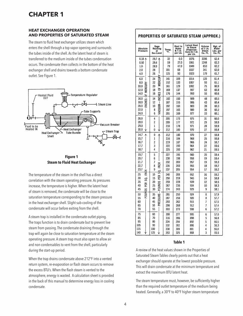
The steam to fluid heat exchanger utilizes steam which enters the shell through a top vapor opening and surrounds the tubes inside of the shell. As the latent heat of steam is transferred to the medium inside of the tubes condensation occurs. The condensate then collects in the bottom of the heat exchanger shell and drains towards a bottom condensate outlet. See Figure 1.
Figure 1 Steam to Fluid Heat Exchanger
The temperature of the steam in the shell has a direct correlation with the steam operating pressure. As pressures increase, the temperature is higher. When the latent heat of steam is removed, the condensate will be close to the saturation temperature corresponding to the steam pressure in the heat exchanger shell. Slight sub-cooling of the condensate will occur before exiting from the shell.
A steam trap is installed in the condensate outlet piping. The traps function is to drain condensate but to prevent live steam from passing. The condensate draining through the trap will again be close to saturation temperature at the steam operating pressure. A steam trap must also open to allow air and non-condensables to vent from the shell, particularly during the start-up period.
When the trap drains condensate above 212°F into a vented return system, re-evaporation or flash steam occurs to remove the excess BTU’s. When the flash steam is vented to the atmosphere, energy is wasted. A calculation sheet is provided in the back of this manual to determine energy loss in cooling condensate.
A review of the heat values shown in the Properties of Saturated Steam Tables clearly points out that a heat exchanger should operate at the lowest possible pressure. This will drain condensate at the minimum temperature and extract the maximum BTU latent heat.
The steam temperature must, however, be sufficiently higher than the required outlet temperature of the medium being heated. Generally, a 30°F to 40°F higher steam temperature
CHAPTER 1
Table 1

5
is an ideal design point. Heat exchangers can be selected for less than 10°F temperature differences, but the size and cost increases. Higher operating pressure and temperature will reduce the size of the heat exchanger, but operating cost will increase due to a higher flash loss as the condensate cools to 212°F after the steam trap. A good rule of thumb is that for every 10°F rise in condensate temperature ahead of the trap, operating costs will increase 1%. If domestic hot water is being heated to 120°F or 140°F using 15 PSI steam, the condensate will drain at 250°F. Using 2 PSI steam, the condensate temperature will be 219°F. The 2 PSI design will lower operating costs 3.1%. This only applies to vented return systems where the flash steam is wasted. The re-evaporation chart (Table 3) shows the lbs. per hundred pounds re-evaporation that occurs when condensate at saturation temperature is drained to a lower pressure. By entering the chart at the initial pressure of 15 PSIG and reading vertically to the 15 PSI pressure drop, the re-evaporation shows 4 lbs. per hundred or 4% loss.
Table 3 shows the quantity of re-evaporation that occurs when condensate at saturation temperature corresponding to PSI Gage at Sea Level is exposed to a lower temperature.
Table 2
Table 3
6
SELECTION OF HEAT EXCHANGER CONTROL SYSTEMS
The selection of equipment for efficient operation will vary depending on design pressure of the heat exchanger, the amount of time the heat exchanger is in actual operation; the initial and final temperature of the fluid being heated.
As pointed out in Chapter 1, the heat exchanger steam operating pressure should be at the minimum pressure that provides adequate heat transfer to minimize the condensate temperature ahead of the steam trap.
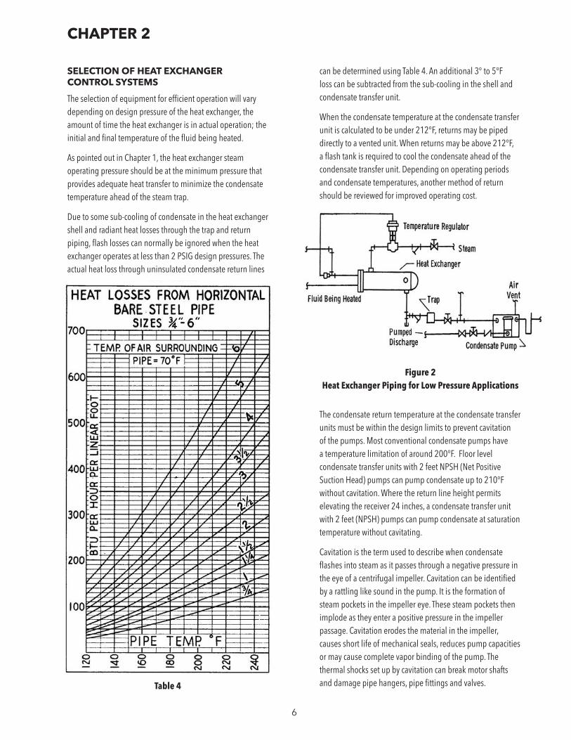
Due to some sub-cooling of condensate in the heat exchanger shell and radiant heat losses through the trap and return piping, flash losses can normally be ignored when the heat exchanger operates at less than 2 PSIG design pressures. The actual heat loss through uninsulated condensate return lines
can be determined using Table 4. An additional 3° to 5°F loss can be subtracted from the sub-cooling in the shell and condensate transfer unit.
When the condensate temperature at the condensate transfer unit is calculated to be under 212°F, returns may be piped directly to a vented unit. When returns may be above 212°F, a flash tank is required to cool the condensate ahead of the condensate transfer unit. Depending on operating periods and condensate temperatures, another method of return should be reviewed for improved operating cost.
Figure 2 Heat Exchanger Piping for Low Pressure Applications
The condensate return temperature at the condensate transfer units must be within the design limits to prevent cavitation of the pumps. Most conventional condensate pumps have a temperature limitation of around 200°F. Floor level condensate transfer units with 2 feet NPSH (Net Positive Suction Head) pumps can pump condensate up to 210°F without cavitation. Where the return line height permits elevating the receiver 24 inches, a condensate transfer unit with 2 feet (NPSH) pumps can pump condensate at saturation temperature without cavitating.
Cavitation is the term used to describe when condensate flashes into steam as it passes through a negative pressure in the eye of a centrifugal impeller. Cavitation can be identified by a rattling like sound in the pump. It is the formation of steam pockets in the impeller eye. These steam pockets then implode as they enter a positive pressure in the impeller passage. Cavitation erodes the material in the impeller, causes short life of mechanical seals, reduces pump capacities or may cause complete vapor binding of the pump. The thermal shocks set up by cavitation can break motor shafts and damage pipe hangers, pipe fittings and valves.
CHAPTER 2
Table 4
7
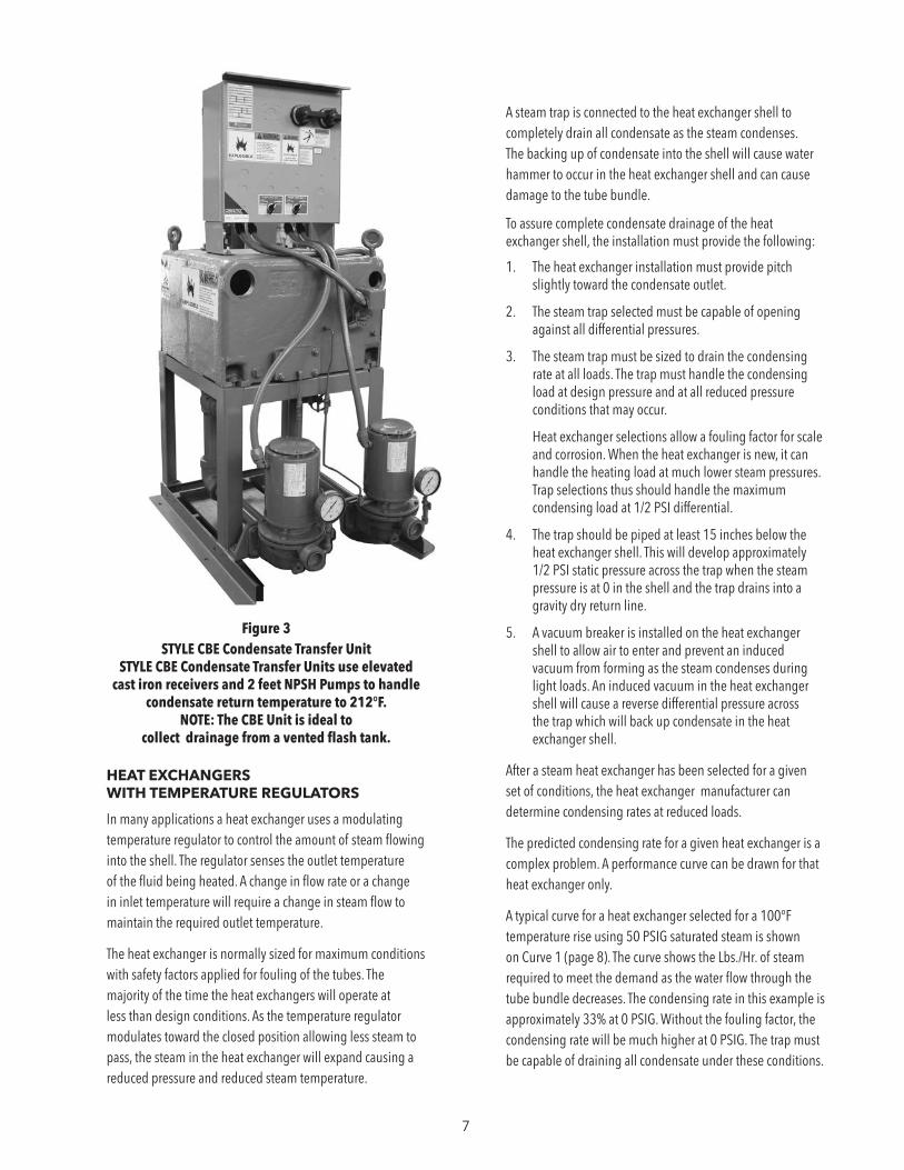
Figure 3 STYLE CBE Condensate Transfer Unit
STYLE CBE Condensate Transfer Units use elevated cast iron receivers and 2 feet NPSH Pumps to handle
condensate return temperature to 212°F. NOTE: The CBE Unit is ideal to
collect drainage from a vented flash tank.
HEAT EXCHANGERS WITH TEMPERATURE REGULATORS
In many applications a heat exchanger uses a modulating temperature regulator to control the amount of steam flowing into the shell. The regulator senses the outlet temperature of the fluid being heated. A change in flow rate or a change in inlet temperature will require a change in steam flow to maintain the required outlet temperature.
The heat exchanger is normally sized for maximum conditions with safety factors applied for fouling of the tubes. The majority of the time the heat exchangers will operate at less than design conditions. As the temperature regulator modulates toward the closed position allowing less steam to pass, the steam in the heat exchanger will expand causing a reduced pressure and reduced steam temperature.
A steam trap is connected to the heat exchanger shell to completely drain all condensate as the steam condenses. The backing up of condensate into the shell will cause water hammer to occur in the heat exchanger shell and can cause damage to the tube bundle.
To assure complete condensate drainage of the heat exchanger shell, the installation must provide the following:
1. The heat exchanger installation must provide pitch slightly toward the condensate outlet.
2. The steam trap selected must be capable of opening against all differential pressures.
3. The steam trap must be sized to drain the condensing rate at all loads. The trap must handle the condensing load at design pressure and at all reduced pressure conditions that may occur.
Heat exchanger selections allow a fouling factor for scale and corrosion. When the heat exchanger is new, it can handle the heating load at much lower steam pressures. Trap selections thus should handle the maximum condensing load at 1/2 PSI differential.
4. The trap should be piped at least 15 inches below the heat exchanger shell. This will develop approximately 1/2 PSI static pressure across the trap when the steam pressure is at 0 in the shell and the trap drains into a gravity dry return line.
5. A vacuum breaker is installed on the heat exchanger shell to allow air to enter and prevent an induced vacuum from forming as the steam condenses during light loads. An induced vacuum in the heat exchanger shell will cause a reverse differential pressure across the trap which will back up condensate in the heat exchanger shell.
After a steam heat exchanger has been selected for a given set of conditions, the heat exchanger manufacturer can determine condensing rates at reduced loads.
The predicted condensing rate for a given heat exchanger is a complex problem. A performance curve can be drawn for that heat exchanger only.
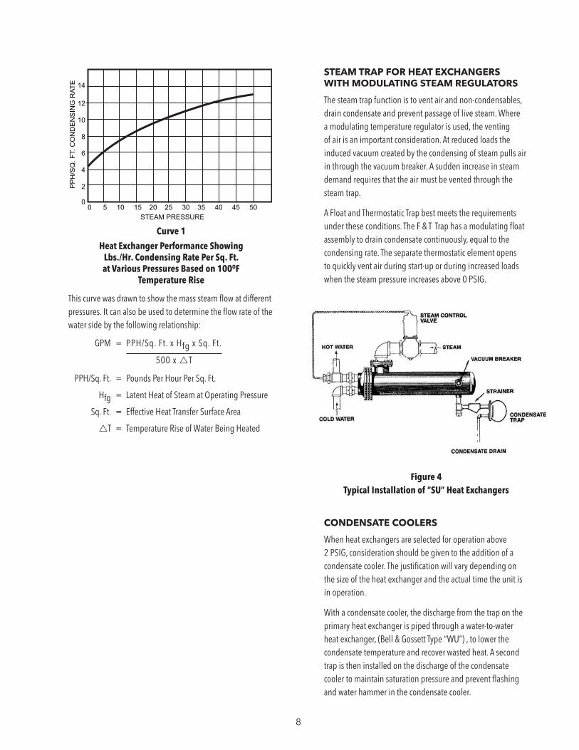
A typical curve for a heat exchanger selected for a 100°F temperature rise using 50 PSIG saturated steam is shown on Curve 1 (page 8). The curve shows the Lbs./Hr. of steam required to meet the demand as the water flow through the tube bundle decreases. The condensing rate in this example is approximately 33% at 0 PSIG. Without the fouling factor, the condensing rate will be much higher at 0 PSIG. The trap must be capable of draining all condensate under these conditions.
8
This curve was drawn to show the mass steam flow at different pressures. It can also be used to determine the flow rate of the water side by the following relationship:
GPM = PPH/Sq. Ft. x Hfg x Sq. Ft.
500 x T
PPH/Sq. Ft. = Pounds Per Hour Per Sq. Ft.
Hfg = Latent Heat of Steam at Operating Pressure
Sq. Ft. = Effective Heat Transfer Surface Area
T = Temperature Rise of Water Being Heated
STEAM TRAP FOR HEAT EXCHANGERS WITH MODULATING STEAM REGULATORS
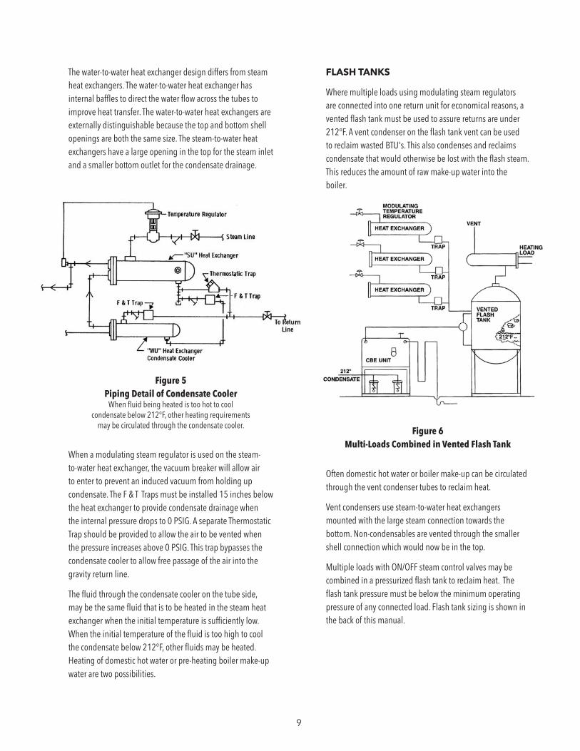
The steam trap function is to vent air and non-condensables, drain condensate and prevent passage of live steam. Where a modulating temperature regulator is used, the venting of air is an important consideration. At reduced loads the induced vacuum created by the condensing of steam pulls air in through the vacuum breaker. A sudden increase in steam demand requires that the air must be vented through the steam trap.
A Float and Thermostatic Trap best meets the requirements under these conditions. The F & T Trap has a modulating float assembly to drain condensate continuously, equal to the condensing rate. The separate thermostatic element opens to quickly vent air during start-up or during increased loads when the steam pressure increases above 0 PSIG.
Figure 4 Typical Installation of “SU” Heat Exchangers
CONDENSATE COOLERS
When heat exchangers are selected for operation above 2 PSIG, consideration should be given to the addition of a condensate cooler. The justification will vary depending on the size of the heat exchanger and the actual time the unit is in operation.
With a condensate cooler, the discharge from the trap on the primary heat exchanger is piped through a water-to-water heat exchanger, (Bell & Gossett Type “WU”) , to lower the condensate temperature and recover wasted heat. A second trap is then installed on the discharge of the condensate cooler to maintain saturation pressure and prevent flashing and water hammer in the condensate cooler.
Curve 1
Heat Exchanger Performance Showing Lbs./Hr. Condensing Rate Per Sq. Ft. at Various Pressures Based on 100OF
Temperature Rise
0 5 10 15 20 25 30 35 40 45 50 STEAM PRESSURE
14
12
10
8
6
4
2
0
PP
H/S
Q. F
T. C
ON
DE
NS
ING
RAT
E
9
The water-to-water heat exchanger design differs from steam heat exchangers. The water-to-water heat exchanger has internal baffles to direct the water flow across the tubes to improve heat transfer. The water-to-water heat exchangers are externally distinguishable because the top and bottom shell openings are both the same size. The steam-to-water heat exchangers have a large opening in the top for the steam inlet and a smaller bottom outlet for the condensate drainage.
Figure 5 Piping Detail of Condensate Cooler
When fluid being heated is too hot to cool condensate below 212°F, other heating requirements
may be circulated through the condensate cooler.
When a modulating steam regulator is used on the steam-to-water heat exchanger, the vacuum breaker will allow air to enter to prevent an induced vacuum from holding up condensate. The F & T Traps must be installed 15 inches below the heat exchanger to provide condensate drainage when the internal pressure drops to 0 PSIG. A separate Thermostatic Trap should be provided to allow the air to be vented when the pressure increases above 0 PSIG. This trap bypasses the condensate cooler to allow free passage of the air into the gravity return line.
The fluid through the condensate cooler on the tube side, may be the same fluid that is to be heated in the steam heat exchanger when the initial temperature is sufficiently low. When the initial temperature of the fluid is too high to cool the condensate below 212°F, other fluids may be heated. Heating of domestic hot water or pre-heating boiler make-up water are two possibilities.
FLASH TANKS
Where multiple loads using modulating steam regulators are connected into one return unit for economical reasons, a vented flash tank must be used to assure returns are under 212°F. A vent condenser on the flash tank vent can be used to reclaim wasted BTU's. This also condenses and reclaims condensate that would otherwise be lost with the flash steam. This reduces the amount of raw make-up water into the boiler.
Figure 6 Multi-Loads Combined in Vented Flash Tank
Often domestic hot water or boiler make-up can be circulated through the vent condenser tubes to reclaim heat.
Vent condensers use steam-to-water heat exchangers mounted with the large steam connection towards the bottom. Non-condensables are vented through the smaller shell connection which would now be in the top.
Multiple loads with ON/OFF steam control valves may be combined in a pressurized flash tank to reclaim heat. The flash tank pressure must be below the minimum operating pressure of any connected load. Flash tank sizing is shown in the back of this manual.
10
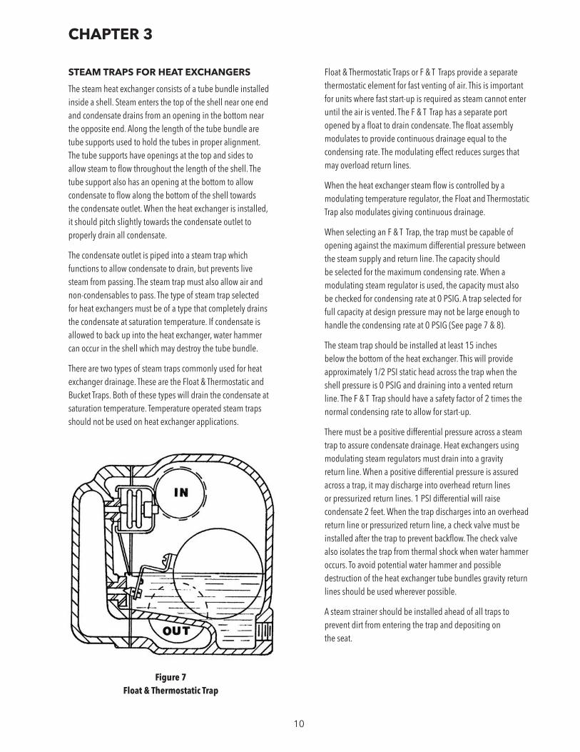
STEAM TRAPS FOR HEAT EXCHANGERS
The steam heat exchanger consists of a tube bundle installed inside a shell. Steam enters the top of the shell near one end and condensate drains from an opening in the bottom near the opposite end. Along the length of the tube bundle are tube supports used to hold the tubes in proper alignment. The tube supports have openings at the top and sides to allow steam to flow throughout the length of the shell. The tube support also has an opening at the bottom to allow condensate to flow along the bottom of the shell towards the condensate outlet. When the heat exchanger is installed, it should pitch slightly towards the condensate outlet to properly drain all condensate.
The condensate outlet is piped into a steam trap which functions to allow condensate to drain, but prevents live steam from passing. The steam trap must also allow air and non-condensables to pass. The type of steam trap selected for heat exchangers must be of a type that completely drains the condensate at saturation temperature. If condensate is allowed to back up into the heat exchanger, water hammer can occur in the shell which may destroy the tube bundle.
There are two types of steam traps commonly used for heat exchanger drainage. These are the Float & Thermostatic and Bucket Traps. Both of these types will drain the condensate at saturation temperature. Temperature operated steam traps should not be used on heat exchanger applications.
Figure 7 Float & Thermostatic Trap
Float & Thermostatic Traps or F & T Traps provide a separate thermostatic element for fast venting of air. This is important for units where fast start-up is required as steam cannot enter until the air is vented. The F & T Trap has a separate port opened by a float to drain condensate. The float assembly modulates to provide continuous drainage equal to the condensing rate. The modulating effect reduces surges that may overload return lines.
When the heat exchanger steam flow is controlled by a modulating temperature regulator, the Float and Thermostatic Trap also modulates giving continuous drainage.
When selecting an F & T Trap, the trap must be capable of opening against the maximum differential pressure between the steam supply and return line. The capacity should be selected for the maximum condensing rate. When a modulating steam regulator is used, the capacity must also be checked for condensing rate at 0 PSIG. A trap selected for full capacity at design pressure may not be large enough to handle the condensing rate at 0 PSIG (See page 7 & 8).
The steam trap should be installed at least 15 inches below the bottom of the heat exchanger. This will provide approximately 1/2 PSI static head across the trap when the shell pressure is 0 PSIG and draining into a vented return line. The F & T Trap should have a safety factor of 2 times the normal condensing rate to allow for start-up.
There must be a positive differential pressure across a steam trap to assure condensate drainage. Heat exchangers using modulating steam regulators must drain into a gravity return line. When a positive differential pressure is assured across a trap, it may discharge into overhead return lines or pressurized return lines. 1 PSI differential will raise condensate 2 feet. When the trap discharges into an overhead return line or pressurized return line, a check valve must be installed after the trap to prevent backflow. The check valve also isolates the trap from thermal shock when water hammer occurs. To avoid potential water hammer and possible destruction of the heat exchanger tube bundles gravity return lines should be used wherever possible.
A steam strainer should be installed ahead of all traps to prevent dirt from entering the trap and depositing on the seat.
CHAPTER 3
11
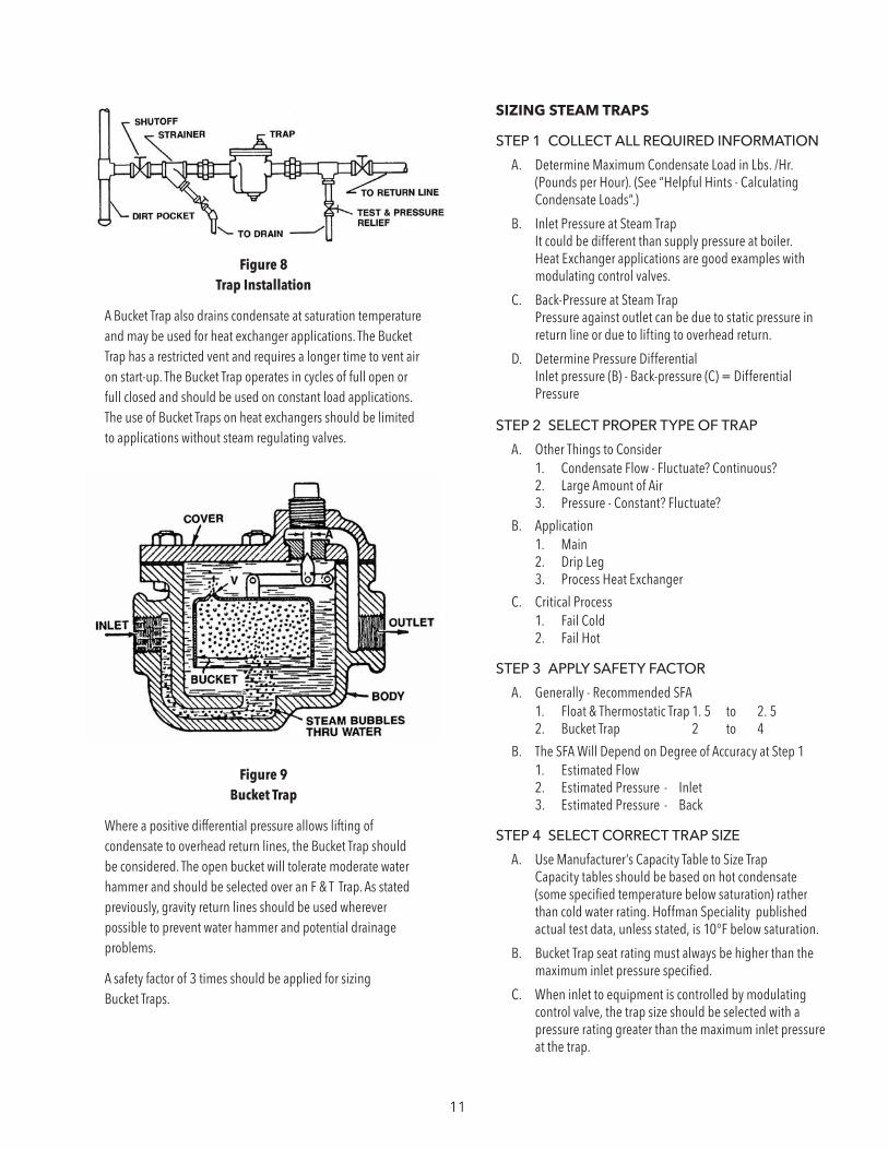
Figure 8 Trap Installation
A Bucket Trap also drains condensate at saturation temperature and may be used for heat exchanger applications. The Bucket Trap has a restricted vent and requires a longer time to vent air on start-up. The Bucket Trap operates in cycles of full open or full closed and should be used on constant load applications. The use of Bucket Traps on heat exchangers should be limited to applications without steam regulating valves.
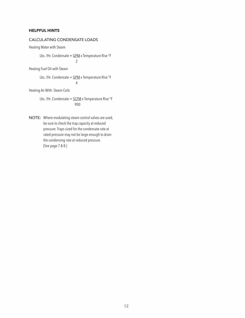
Figure 9 Bucket Trap
Where a positive differential pressure allows lifting of condensate to overhead return lines, the Bucket Trap should be considered. The open bucket will tolerate moderate water hammer and should be selected over an F & T Trap. As stated previously, gravity return lines should be used wherever possible to prevent water hammer and potential drainage problems.
A safety factor of 3 times should be applied for sizing Bucket Traps.
SIZING STEAM TRAPS
STEP 1 COLLECT ALL REQUIRED INFORMATION
A. Determine Maximum Condensate Load in Lbs. /Hr. (Pounds per Hour). (See “Helpful Hints - Calculating Condensate Loads”.)
B. Inlet Pressure at Steam Trap It could be different than supply pressure at boiler. Heat Exchanger applications are good examples with modulating control valves.
C. Back-Pressure at Steam Trap Pressure against outlet can be due to static pressure in return line or due to lifting to overhead return.
D. Determine Pressure Differential Inlet pressure (B) - Back-pressure (C) = Differential Pressure
STEP 2 SELECT PROPER TYPE OF TRAP
A. Other Things to Consider1. Condensate Flow - Fluctuate? Continuous?2. Large Amount of Air3. Pressure - Constant? Fluctuate?
B. Application1. Main2. Drip Leg3. Process Heat Exchanger
C. Critical Process1. Fail Cold2. Fail Hot
STEP 3 APPLY SAFETY FACTOR
A. Generally - Recommended SFA1. Float & Thermostatic Trap 1. 5 to 2. 52. Bucket Trap 2 to 4
B. The SFA Will Depend on Degree of Accuracy at Step 11. Estimated Flow 2. Estimated Pressure - Inlet3. Estimated Pressure - Back
STEP 4 SELECT CORRECT TRAP SIZE
A. Use Manufacturer’s Capacity Table to Size Trap Capacity tables should be based on hot condensate (some specified temperature below saturation) rather than cold water rating. Hoffman Speciality published actual test data, unless stated, is 10°F below saturation.
B. Bucket Trap seat rating must always be higher than the maximum inlet pressure specified.
C. When inlet to equipment is controlled by modulating control valve, the trap size should be selected with a pressure rating greater than the maximum inlet pressure at the trap.
12
HELPFUL HINTS
CALCULATING CONDENSATE LOADS
Heating Water with Steam
Lbs. /Hr. Condensate = GPM x Temperature Rise °F 2
Heating Fuel Oil with Steam
Lbs. /Hr. Condensate = GPM x Temperature Rise °F 4
Heating Air With· Steam Coils
Lbs. /Hr. Condensate = SCFM x Temperature Rise °F 900
NOTE: Where modulating steam control valves are used, be sure to check the trap capacity at reduced pressure. Traps sized for the condensate rate at rated pressure may not be large enough to drain the condensing rate at reduced pressure. (See page 7 & 8.)
13
STEAM TEMPERATURE & PRESSURE REGULATORS
A heat exchanger should be selected to operate at the minimum pressure that will provide adequate steam temperature. A reasonable guide would be to select a steam saturation temperature approximately 30°F above the required temperature of the fluid being heated. Operating at the minimum pressure reduces the temperature of the condensate draining through the trap. This reduces the amount of flash steam or re-evaporation that occurs and reduces operating costs. The steam pressure should never be higher than the water pressure in the tube bundle. This will assure that the water in the tube bundle will not boil possibly causing water hammer in the tubes.
The steam pressure can be regulated using a steam Pressure Reducing Valve or a Combination Pressure Reducing & Temperature Regulating Valve.
The selection of Temperature Regulators include self contained styles or pneumatic pilot operated styles. The self contained styles use a sensing bulb immersed in the fluid being heated. The sensing bulb contains a volatile fluid which when ‘heated to the design temperature range, boils causing a vapor pressure to occur inside the bulb. This pressure is transmitted through a capillary tube to a bellows or diaphragm inside the main valve. The bellows or diaphragm then acts to open or close the main valve. In some Regulators, the sensing bulb and bellows may be filled with a fluid. As the fluid is heated, it expands causing the bellows in the main valve to move. Direct Operating Regulators generally require a 3°F to 10°F temperature change to respond.
Pneumatic Operated Regulators use a separate air operated pilot to control air loading to the main valve. This may be directly loaded to a bellows or diaphragm on the main valve or through an air pilot assembly. Pneumatic Operated Temperature Pilots generally respond to a 1/4°F to 1/2°F temperature change and respond approximately 10 times faster than a Self Contained Temperature Regulator.
The use of Self Contained Temperature Regulators should be confined to applications with storage tanks or where temperatures are not critical. Instantaneous heaters or applications requiring close temperature and fast response control should use Pneumatic Type Regulators.
CHAPTER 4
Where both temperature and pressure control is required, a Combination Pilot Operated Steam Regulator may be used.
The Steam Regulating Valve is sized based on the required Lbs. /Hr. steam flow rate and the allowable pressure drop across the valve. The operating pressure of the heat exchanger must be lower than the actual steam supply pressure due to the pressure drop across the valve seat.
Steam Temperature Regulators are available as single seated or double seated types. The double seated valves have less pressure drop for a given size. However, they do not provide dead end or tight shut-off. A double seated valve is not normally used on heat exchanger applications as steam leakage across the valve may cause overheating during periods of no flow.
SIZING STEAM TEMPERATURE/PRESSURE REGULATORS
STEP 1 COLLECT ALL REQUIRED INFORMATION
A. Determine the Available Steam Pressure to the Regulator The available supply pressure may be different than the boiler pressure due to line losses or Pressure Reducing Valves.
B. Operating Pressure of the Heat Exchanger The operating pressure should be kept to the minimum pressure that will provide reasonable heat transfer as explained in Chapter 1. The operating pressure must be lower than the available steam supply due to pressure loss across the Regulator valve seat.
C. Determine Maximum Steam Condensing Loads in Lbs. /Hr. Applications for heating water use the formula:
Lbs. /Hr. Condensed = GPM Heated x Temp. Rise °F 2
Applications for heating oil, use the formula:
Lbs. /Hr. Condensed = GPM Heated x Temp. Rise °F 4
STEP 2 DETERMINE TYPE OF REGULATOR REQUIRED
A. Temperature Control There are two basic types of temperature controllers, one is the self contained type, and the second is a pneumatic pilot operated type. Where temperature fluctuations and response times are not critical, Self Contained Regulators may be used. The Pneumatic Pilot Operated Regulators have a faster response time and operate at a closer differential temperature range. They should be considered for critical applications including instantaneous heaters.
Self Contained Temperature Regulators - Hoffman Series 11OO.
Pneumatic Pilot Operated Temperature Regulators - Hoffman Type SA.
14
B. Pressure Regulators Steam Pressure reductions up to one-half of the initial pressure can be achieved by proper selection of the Temperature Regulator. Where greater pressure reductions are required, a separate Pressure Reducing Valve or Combination Regulator having a pressure and temperature pilot must be used.
When more than one heat exchanger is being used, a separate Pressure Reducing Valve is generally the most economical. When only one heat exchanger is being applied in the area, a Combination Pressure Reducing and Temperature Regulator should be considered. The Combination Regulators are available with direct operated temperature pilots or pneumatic pilots - the same as shown under temperature control.
Combination Pressure Temperature Regulators - Hoffman Series 2000.
C. Temperature and Pressure Regulator Valves are available as single seated or double seated. The double seated valves do not provide dead end service and are not normally used on heat exchanger applications.
STEP 3 SELECTION OF SPECIFIC REGULATORS
A. Use of Capacity Tables in Manufacturer’s Catalog to Select Valve Size.
Hoffman Speciality Catalogs actual test data showing maximum steam capacity based on differential pressure drop across the valve seat.
B. Select Temperature Control Assembly. Temperature controllers operate within a specific temperature range. The controller should be selected to operate as close to midpoint as possible. This will allow for field changes in temperature setting.
NOTE: Steam delivered to the Regulator should be dry steam. A Steam Trap is recommended ahead of all Temperature and Pressure Regulators. Steam strainers should also be provided ahead of all Regulators to prevent dirt from entering the valve.
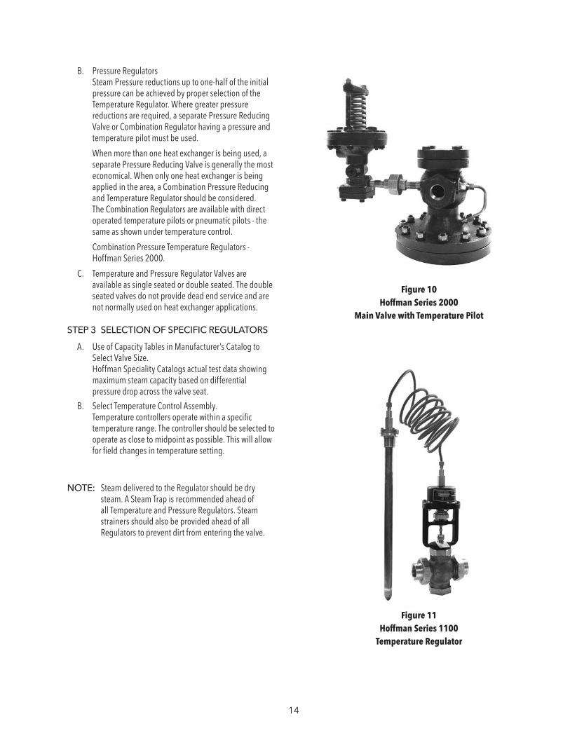
Figure 10 Hoffman Series 2000
Main Valve with Temperature Pilot
Figure 11 Hoffman Series 1100
Temperature Regulator
15
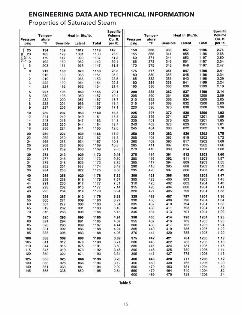
ENGINEERING DATA AND TECHNICAL INFORMATIONProperties of Saturated Steam
Table 5
16
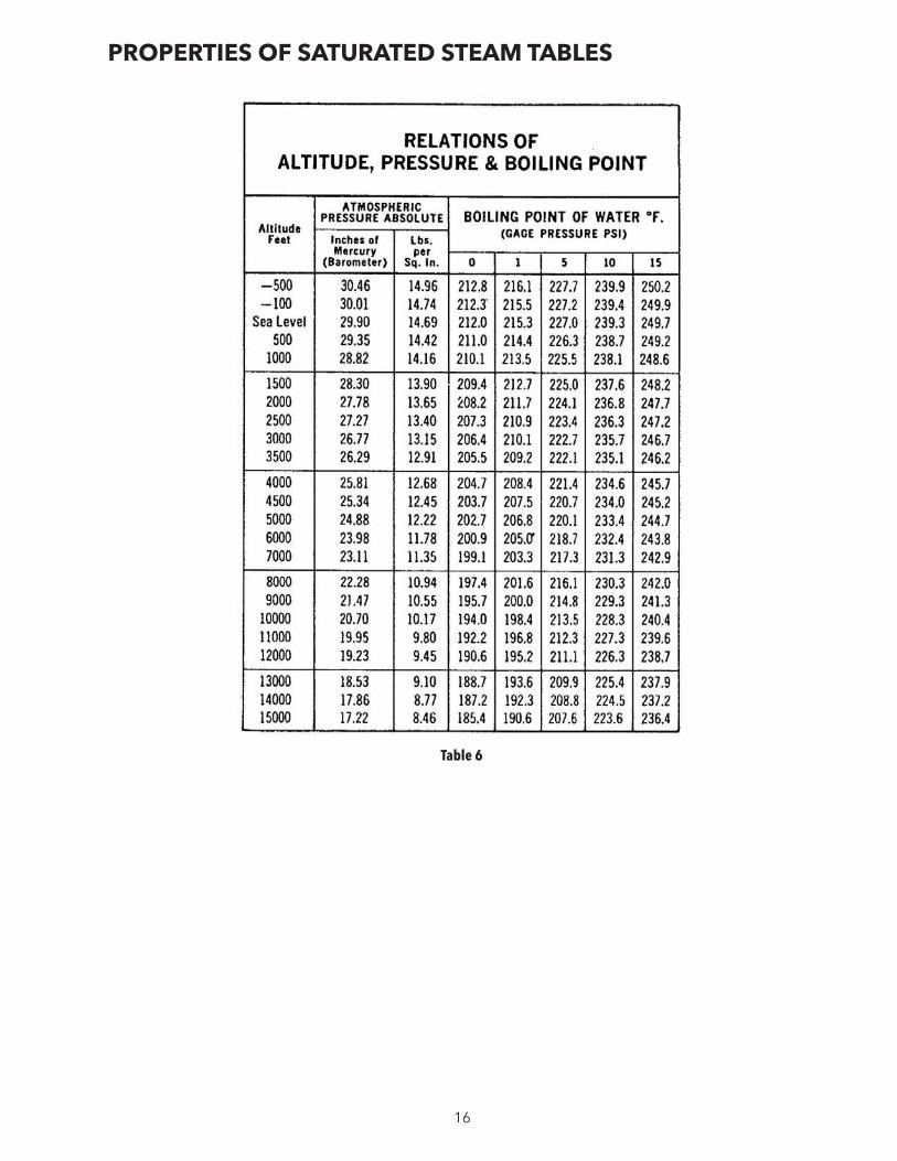
PROPERTIES OF SATURATED STEAM TABLES
Table 6
17
CONVERSION FACTORS
One Boiler Horsepower = 140 Sq. Ft. EDR or 33,475 BTU/Hr. or 34.5 Lbs./Hr. Steam at 212°F
1,000 Sq. Ft. EDR Yields .5 GPM Condensate
To Convert Sq, Ft. EDR to Lbs. of Condensate - Divide Sq. Ft. by 4
.25 Lbs./Hr. Condensate = 1 Sq. Ft. EDR
One Sq. Ft. EDR (Steam) = 240 BTU/Hr. with 215°F Steam Filling Radiator and 70°F Air Surrounding Radiator.
To Convert BTU/Hr. to Lbs./Hr. Divide BTU/Hr. By 960
One PSI = 2.307 Feet Water Column (Cold) One PSI = 2.41 Feet Water Column (Hot) One PSI = 2.036 Inches Mercury One Inch Mercury = 13.6 Inches Water Column
Sizing Boiler Feed or Condensate Return Pumps:
If Boiler is under 50 PSI, Size Pump to Discharge at 5 PSI Above Working Pressure.
If Boiler is Over 50 PSI, Size Pump to Discharge at 10 PSI Above Working Pressure.
Size Condensate Receivers for 1 Min. Net Storage Capacity Based on Return Rate.
Size Boiler Feed Receivers for System Capacity (Normally Estimated at 10 Min.)
Size Condensate Pumps at 2 to 3 Times Condensate Return Rate.
Size Boiler Feed Pumps at 2 Times Boiler Evaporation Rate or .14 GPM/Boiler HP (Continuous Running Boiler Pumps May Be Sized at 1-½ Times Boiler Evaporation Rate or .104 GPM/Boiler HP.
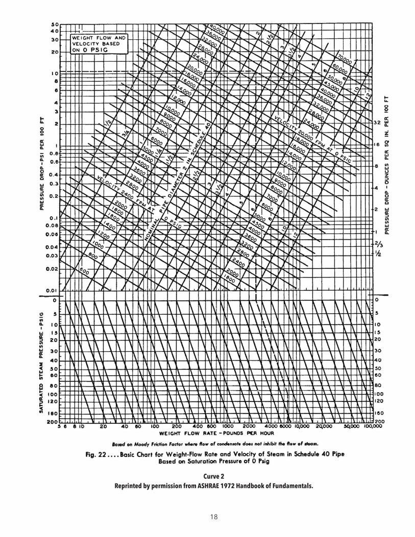
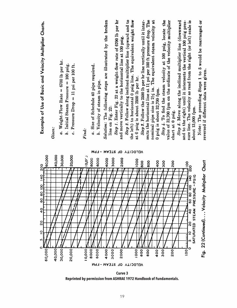
SIZING STEAM LINESVELOCITY OF STEAM
General Heating Applications 4,000 to 6, 000 FPM Process Pipe 6,000 to 12,000 FPM
SAMPLE PROBLEM USING STEAM VELOCITY CHARTS ON FOLLOWING PAGES:
General Heating Application 2,000 Lbs. /Hr. Required at 30 PSI Supply Pressure
SIZE PIPE AND DETERMINE VELOCITY AND PRESSURE DROP
STEP 1 Correct 30 PSI flow rate to 0 PSI on basic chart. This is done by entering at bottom at 2,000 Lbs./Hr. Follow this point vertically to the 30 Lb. line, then follow slope to the 0 PSI line.
STEP 2 Draw vertical line from 0 point into upper curve. Stop at some point above 6, 000 FPM as velocity shown is 0 PSI steam and will require correction.
STEP 3 Try 3" pipe showing 10, 000 FPM velocity and pressure drop of approximately .9 PSI per 100 foot.
STEP 4 Use velocity multiplier chart. Enter left column at 10,000 FPM, follow sloping line to 30 PSI, read corrected velocity of 6, 000 FPM in right column.
NOTE: 1. You can use velocity chart to correct 6, 000 FPM required velocity to 10, 000 FPM before using basic chart.
2. Heat exchanger steam entrance nozzles are normally sized at reduced velocities to avoid impingement damage to the tube bundle. Check with manufacturer.
18
Curve 2 Reprinted by permission from ASHRAE 1972 Handbook of Fundamentals.
19
Curve 3 Reprinted by permission from ASHRAE 1972 Handbook of Fundamentals.
20
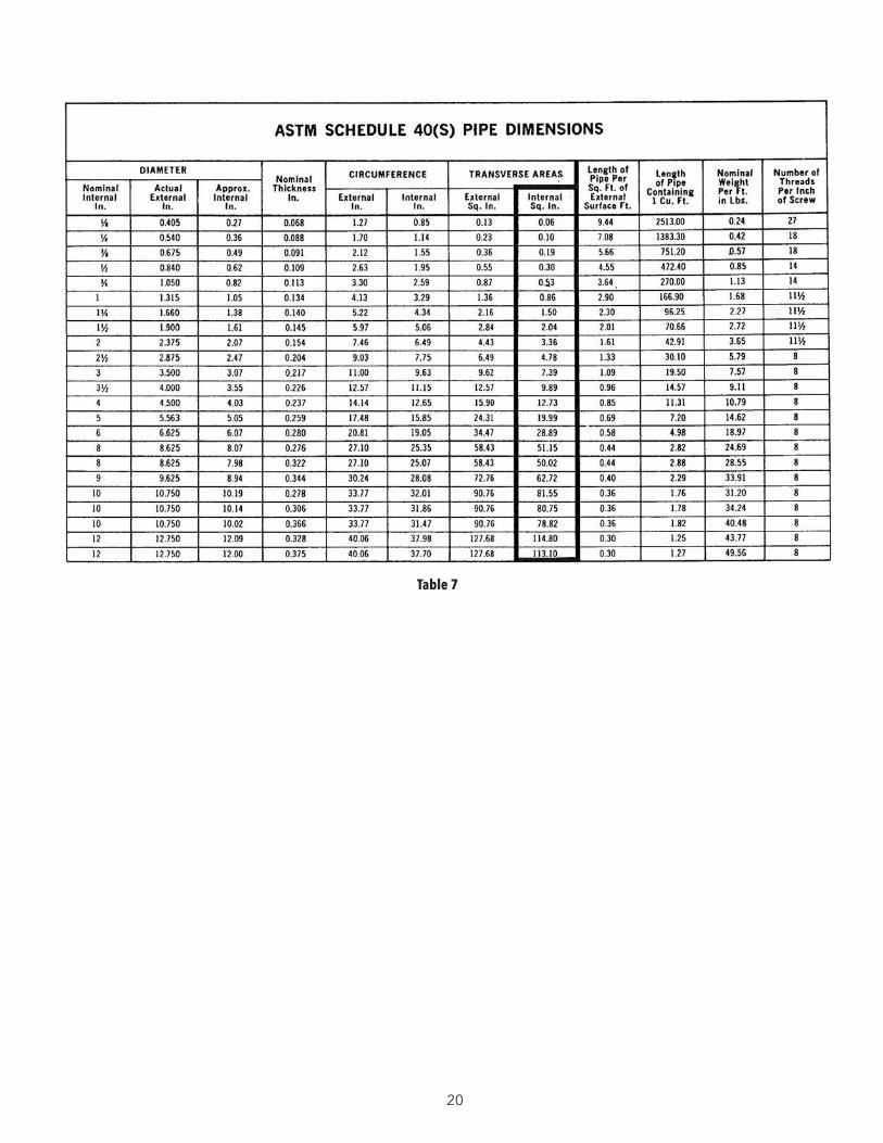
Table 7
21
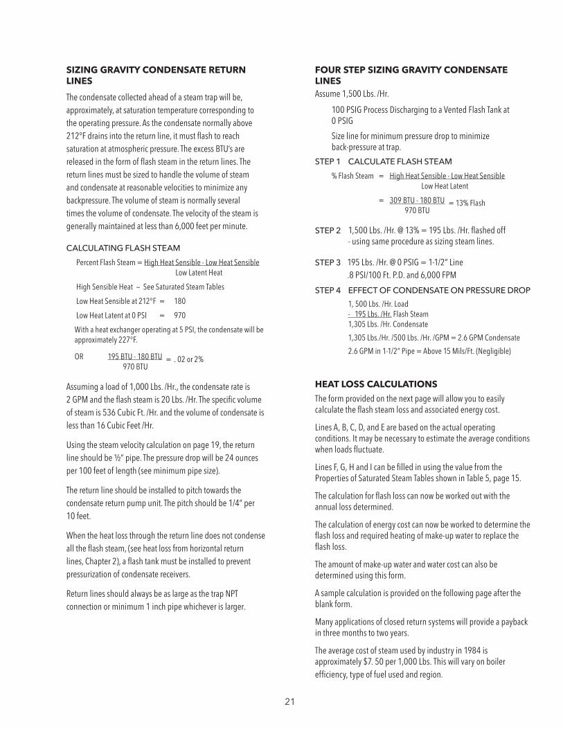
SIZING GRAVITY CONDENSATE RETURN LINES
The condensate collected ahead of a steam trap will be, approximately, at saturation temperature corresponding to the operating pressure. As the condensate normally above 212°F drains into the return line, it must flash to reach saturation at atmospheric pressure. The excess BTU’s are released in the form of flash steam in the return lines. The return lines must be sized to handle the volume of steam and condensate at reasonable velocities to minimize any backpressure. The volume of steam is normally several times the volume of condensate. The velocity of the steam is generally maintained at less than 6,000 feet per minute.
CALCULATING FLASH STEAM
Percent Flash Steam = High Heat Sensible - Low Heat Sensible Low Latent Heat
High Sensible Heat — See Saturated Steam Tables
Low Heat Sensible at 212°F = 180
Low Heat Latent at 0 PSI = 970
With a heat exchanger operating at 5 PSI, the condensate will be approximately 227°F.
OR 195 BTU - 180 BTU = . 02 or 2% 970 BTU
Assuming a load of 1,000 Lbs. /Hr., the condensate rate is 2 GPM and the flash steam is 20 Lbs. /Hr. The specific volume of steam is 536 Cubic Ft. /Hr. and the volume of condensate is less than 16 Cubic Feet /Hr.
Using the steam velocity calculation on page 19, the return line should be ½” pipe. The pressure drop will be 24 ounces per 100 feet of length (see minimum pipe size).
The return line should be installed to pitch towards the condensate return pump unit. The pitch should be 1/4” per 10 feet.
When the heat loss through the return line does not condense all the flash steam, (see heat loss from horizontal return lines, Chapter 2), a flash tank must be installed to prevent pressurization of condensate receivers.
Return lines should always be as large as the trap NPT connection or minimum 1 inch pipe whichever is larger.
FOUR STEP SIZING GRAVITY CONDENSATE LINESAssume 1,500 Lbs. /Hr.
100 PSIG Process Discharging to a Vented Flash Tank at 0 PSIG
Size line for minimum pressure drop to minimize back-pressure at trap.
STEP 1 CALCULATE FLASH STEAM
% Flash Steam = High Heat Sensible - Low Heat Sensible Low Heat Latent
= 309 BTU - 180 BTU = 13% Flash 970 BTU
STEP 2 1,500 Lbs. /Hr. @ 13% = 195 Lbs. /Hr. flashed off - using same procedure as sizing steam lines.
STEP 3 195 Lbs. /Hr. @ 0 PSIG = 1-1/2” Line .8 PSI/100 Ft. P.D. and 6,000 FPM
STEP 4 EFFECT OF CONDENSATE ON PRESSURE DROP
1, 500 Lbs. /Hr. Load - 195 Lbs. /Hr. Flash Steam 1,305 Lbs. /Hr. Condensate
1,305 Lbs./Hr. /500 Lbs. /Hr. /GPM = 2.6 GPM Condensate
2.6 GPM in 1-1/2” Pipe = Above 15 Mils/Ft. (Negligible)
HEAT LOSS CALCULATIONS
The form provided on the next page will allow you to easily calculate the flash steam loss and associated energy cost.
Lines A, B, C, D, and E are based on the actual operating conditions. It may be necessary to estimate the average conditions when loads fluctuate.
Lines F, G, H and I can be filled in using the value from the Properties of Saturated Steam Tables shown in Table 5, page 15.
The calculation for flash loss can now be worked out with the annual loss determined.
The calculation of energy cost can now be worked to determine the flash loss and required heating of make-up water to replace the flash loss.
The amount of make-up water and water cost can also be determined using this form.
A sample calculation is provided on the following page after the blank form.
Many applications of closed return systems will provide a payback in three months to two years.
The average cost of steam used by industry in 1984 is approximately $7. 50 per 1,000 Lbs. This will vary on boiler efficiency, type of fuel used and region.
22
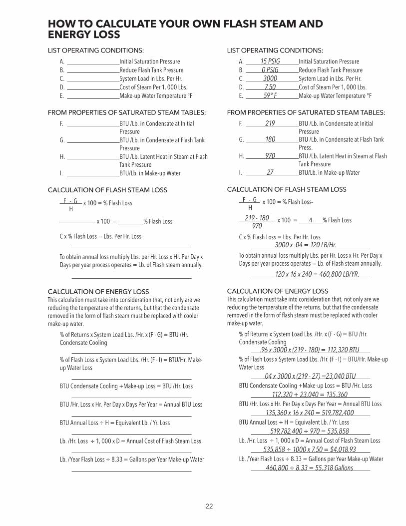
LIST OPERATING CONDITIONS:
A. Initial Saturation PressureB. Reduce Flash Tank PressureC. System Load in Lbs. Per Hr.D. Cost of Steam Per 1, 000 Lbs.E. Make-up Water Temperature °F
FROM PROPERTIES OF SATURATED STEAM TABLES:
F. BTU /Lb. in Condensate at Initial Pressure
G. BTU /Lb. in Condensate at Flash Tank Pressure
H. BTU /Lb. Latent Heat in Steam at Flash Tank Pressure
I. BTU/Lb. in Make-up Water
CALCULATION OF FLASH STEAM LOSS
F - G x 100 = % Flash Loss H
x 100 = % Flash Loss
C x % Flash Loss = Lbs. Per Hr. Loss
To obtain annual loss multiply Lbs. per Hr. Loss x Hr. Per Day x Days per year process operates = Lb. of Flash steam annually.
CALCULATION OF ENERGY LOSSThis calculation must take into consideration that, not only are we reducing the temperature of the returns, but that the condensate removed in the form of flash steam must be replaced with cooler make-up water.
% of Returns x System Load Lbs. /Hr. x (F - G) = BTU /Hr. Condensate Cooling % of Flash Loss x System Load Lbs. /Hr. (F - I) = BTU/Hr. Make-up Water Loss BTU Condensate Cooling +Make-up Loss = BTU /Hr. Loss BTU /Hr. Loss x Hr. Per Day x Days Per Year = Annual BTU Loss BTU Annual Loss ÷ H = Equivalent Lb. / Yr. Loss Lb. /Hr. Loss ÷ 1, 000 x D = Annual Cost of Flash Steam Loss Lb. /Year Flash Loss ÷ 8.33 = Gallons per Year Make-up Water
LIST OPERATING CONDITIONS:
A. 15 PSIG Initial Saturation PressureB. 0 PSIG Reduce Flash Tank PressureC. 3000 System Load in Lbs. Per Hr.D. 7.50 Cost of Steam Per 1, 000 Lbs.E. 59° F Make-up Water Temperature °F
FROM PROPERTIES OF SATURATED STEAM TABLES:
F. 219 BTU /Lb. in Condensate at Initial Pressure
G. 180 BTU /Lb. in Condensate at Flash Tank Press.
H. 970 BTU /Lb. Latent Heat in Steam at Flash Tank Pressure
I. 27 BTU/Lb. in Make-up Water
CALCULATION OF FLASH STEAM LOSS
F - G x 100 = % Flash Loss H
219 - 180 x 100 = 4 % Flash Loss 970C x % Flash Loss = Lbs. Per Hr. Loss 3000 x .04 = 120 LB/Hr.
To obtain annual loss multiply Lbs. per Hr. Loss x Hr. Per Day x Days per year process operates = Lb. of Flash steam annually.
120 x 16 x 240 = 460,800 LB/YR.
CALCULATION OF ENERGY LOSSThis calculation must take into consideration that, not only are we reducing the temperature of the returns, but that the condensate removed in the form of flash steam must be replaced with cooler make-up water.
% of Returns x System Load Lbs. /Hr. x (F - G) = BTU /Hr. Condensate Cooling .96 x 3000 x (219 - 180) = 112,320 BTU % of Flash Loss x System Load Lbs. /Hr. (F - I) = BTU/Hr. Make-up Water Loss .04 x 3000 x (219 - 27) =23,040 BTU BTU Condensate Cooling +Make-up Loss = BTU /Hr. Loss 112,320 + 23,040 = 135,360 BTU /Hr. Loss x Hr. Per Day x Days Per Year = Annual BTU Loss 135,360 x 16 x 240 = 519,782,400 BTU Annual Loss ÷ H = Equivalent Lb. / Yr. Loss 519,782,400 ÷ 970 = 535,858 Lb. /Hr. Loss ÷ 1, 000 x D = Annual Cost of Flash Steam Loss 535,858 ÷ 1000 x 7.50 = $4,018.93 Lb. /Year Flash Loss ÷ 8.33 = Gallons per Year Make-up Water 460,800 ÷ 8.33 = 55,318 Gallons
HOW TO CALCULATE YOUR OWN FLASH STEAM AND ENERGY LOSS

23
1. CALCULATE THE AMOUNT OF CONDENSATE ENTERING THE FLASH TANKThe amount of condensate entering the tank will be the summation of the steam consuming capacity of all equipment to be connected to the flash tank. DO NOT take the trap capacities of all equipment since they are usually sized at three times the steam consuming capacity.
2. CALCULATE THE CONDENSATE THAT FLASHES TO STEAM WITHIN THE TANK
FORMULA: % Flash = High Heat Sensible - Low Heat Sensible Low Heat Latent
For example, when 100 Lbs. /Min. are flowing into a properly vented flash tank @ 300°, the following conditions prevail:
Heat in the Liquid @ 300°= 270 BTU/Lb. (53 PSIG) Heat in the Liquid @ 212°= 180 BTU/Lb. ( 0 PSIG)
Latent Heat @ 0 PSIG Steam = 970 BTU /Lb.
Substituting these values in the formula:
% Flash Steam = 270 - 180 = . 092 or 9. 2% 970
Weight of condensate flashed off as steam: 100 Lbs. /Min. @ 9. 2% = 9. 2 Lbs. /Min.
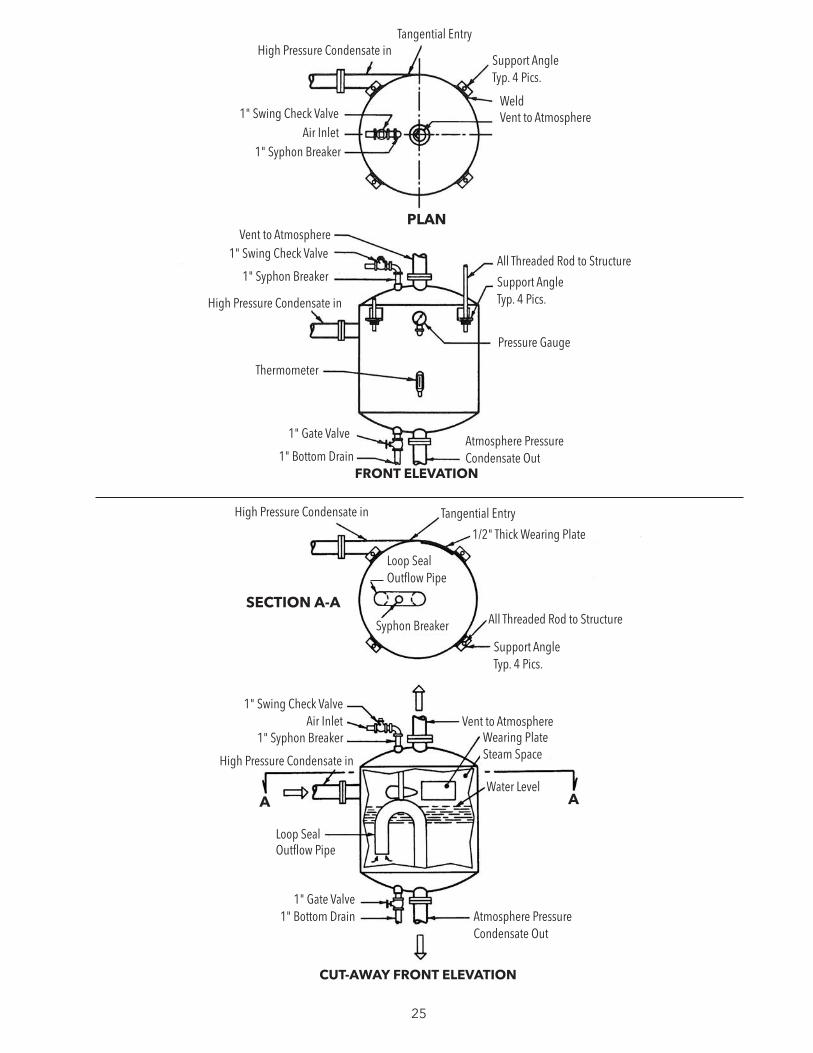
3. SIZING THE STEAM SPACEIf the vent is adequately sized, the steam chamber need only be large enough to take care of the instantaneous flash. Thus, from the example above, there is -
9.2 Lbs. /Min. x 26.80 (Specific Volume of Steam@ 0 PSIG) FT3 /Lb. = 60 Sec. /Min.
4.1 Cu. Ft. /Sec. Flashing
To avoid pressure build-up, take 2 x 4.1 or 8 Ft.3 for steam space. Assuming a tank diameter of 30 inches, solve for height, "A", of Steam Space “S”.
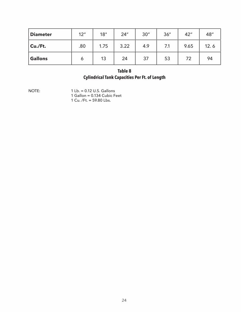
From attached Table 8, a 30" tank has an available capacity of 4.9 Cu./Ft. per ft.
SO: 8 Divided By 4.9 = 1. 63 Ft. or about 20”
4. SIZING THE WATER SPACETo provide stability of flow from the flash tank at least ten minutes of water should be provided. Thus, in the example above –
90.78 Lbs. /of Water per Min x 10 = 907. 80 Lbs. of Water 907.8 Lbs. Divided By 59.80 Lbs./Ft.3 = 15.18 Cu. Ft. 15.18 Cu. Ft. Divided By 4.9 = 3. 09 Ft. – Say 36 Inches
5. TANK SIZEThe tank size is the diameter times the summation of the steam and water space, or in the example —
30” Diameter By (20 + 36) Shell Length = 30” Diameter By 56” High Total Size
6. SIZING THE VENTSize the vent from the tables for low pressure steam. Do not size vent less than two (2) inches.
7. SIZING THE HIGH PRESSURE CONDENSATE PIPINGSize the high pressure condensate line from the condensate tables.
8. SIZING THE ATMOSPHERIC PRESSURE CONDENSATE PIPINGSize the atmospheric condensate line to suit the pump or gravity flow conditions.
9. USE OF HEAT WASTED TO ATMOSPHEREWhere the steam will be vented to atmosphere, consider in the design the use of the flash steam in the building, or run the condensate through heat exchangers in the building to avoid wasting of heat to the atmosphere.
DESIGNING THE FLASH TANK
24
Diameter 12” 18" 24” 30” 36” 42” 48”
Cu./Ft. .80 1.75 3.22 4.9 7.1 9.65 12. 6
Gallons 6 13 24 37 53 72 94
Table 8 Cylindrical Tank Capacities Per Ft. of Length
NOTE: 1 Lb. = 0.12 U.S. Gallons 1 Gallon = 0.134 Cubic Feet 1 Cu. /Ft. = 59.80 Lbs.
25
CUT-AWAY FRONT ELEVATION
FRONT ELEVATION
High Pressure Condensate in
PLAN
Tangential Entry
Support Angle Typ. 4 Pics.
Weld Vent to Atmosphere1" Swing Check Valve
1" Syphon Breaker
All Threaded Rod to Structure
Vent to Atmosphere1" Swing Check Valve
1" Syphon Breaker
High Pressure Condensate in
Support Angle Typ. 4 Pics.
Pressure Gauge
Atmosphere Pressure Condensate Out1" Bottom Drain
1" Gate Valve
Thermometer
Tangential EntryHigh Pressure Condensate in
Loop Seal Outflow Pipe
Syphon Breaker
SECTION A-A
Support Angle Typ. 4 Pics.
All Threaded Rod to Structure
1/2" Thick Wearing Plate
1" Swing Check Valve
1" Syphon BreakerVent to Atmosphere
Wearing PlateSteam Space
Water LevelA A
Loop Seal Outflow Pipe
High Pressure Condensate in
Air Inlet
Atmosphere Pressure Condensate Out
1" Bottom Drain1" Gate Valve
Air Inlet
26
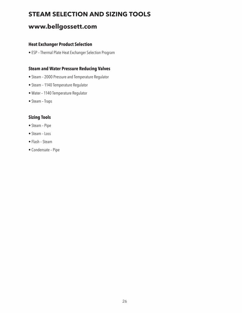
STEAM SELECTION AND SIZING TOOLS
www.bellgossett.com
Heat Exchanger Product Selection
• ESP – Thermal Plate Heat Exchanger Selection Program
Steam and Water Pressure Reducing Valves
• Steam – 2000 Pressure and Temperature Regulator
• Steam – 1140 Temperature Regulator
• Water – 1140 Temperature Regulator
• Steam – Traps
Sizing Tools
• Steam – Pipe
• Steam – Loss
• Flash – Steam
• Condensate – Pipe
Xylem Inc. 8200 N. Austin Avenue Morton Grove, Illinois 60053 Phone: (847) 966-3700 Fax: (847) 965-8379 www.bellgossett.com
Bell & Gossett is a trademark of Xylem Inc. or one of its subsidiaries. © 2016 Xylem Inc. TES-485B October 2016
1) The tissue in plants that brings water upward from the roots; 2) a leading global water technology company.
We’re a global team unified in a common purpose: creating innovative solutions to meet our world’s water needs. Developing new technologies that will improve the way water is used, conserved, and re-used in the future is central to our work. We move, treat, analyze, and return water to the environment, and we help people use water efficiently, in their homes, buildings, factories and farms. In more than 150 countries, we have strong, long-standing relationships with customers who know us for our powerful combination of leading product brands and applications expertise, backed by a legacy of innovation..
For more information on how Xylem can help you, go to www.xyleminc.com
Xylem