steam crackers at mpc - kezdŐlap
TRANSCRIPT
Steam Crackersat MPC

The world of plastics
2

3
What is steamcracking?

4
SC feeds and yields
5
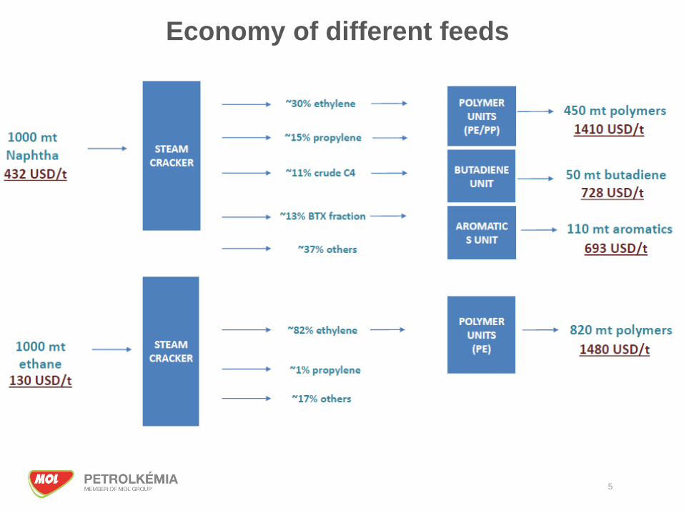
Economy of different feeds
6
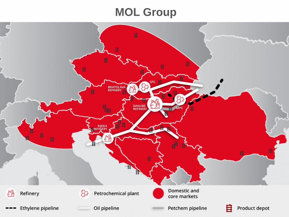
MOL Group

Presenting to [name] 7
? m3 ; ? kg / m3
Presenting to [name] 8
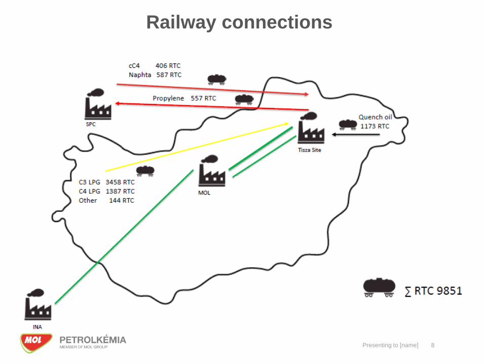
Railway connections

Petchem units of MOL
9
10
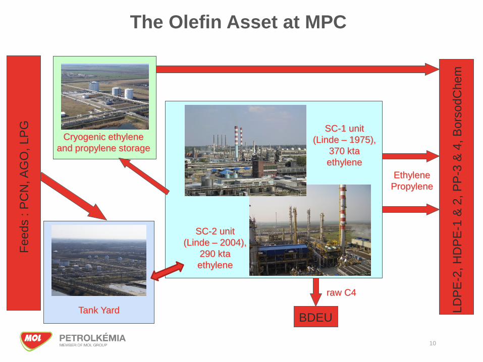
SC-1 unit
(Linde – 1975),
370 kta
ethylene
SC-2 unit
(Linde – 2004),
290 kta
ethylene
Cryogenic ethylene
and propylene storage
LD
PE
-2, H
DP
E-1
& 2
, P
P-3
& 4
, B
ors
odC
hem
Ethylene
Propylene
Feeds : P
CN
, A
GO
, LP
G
raw C4
BDEUTank Yard
The Olefin Asset at MPC
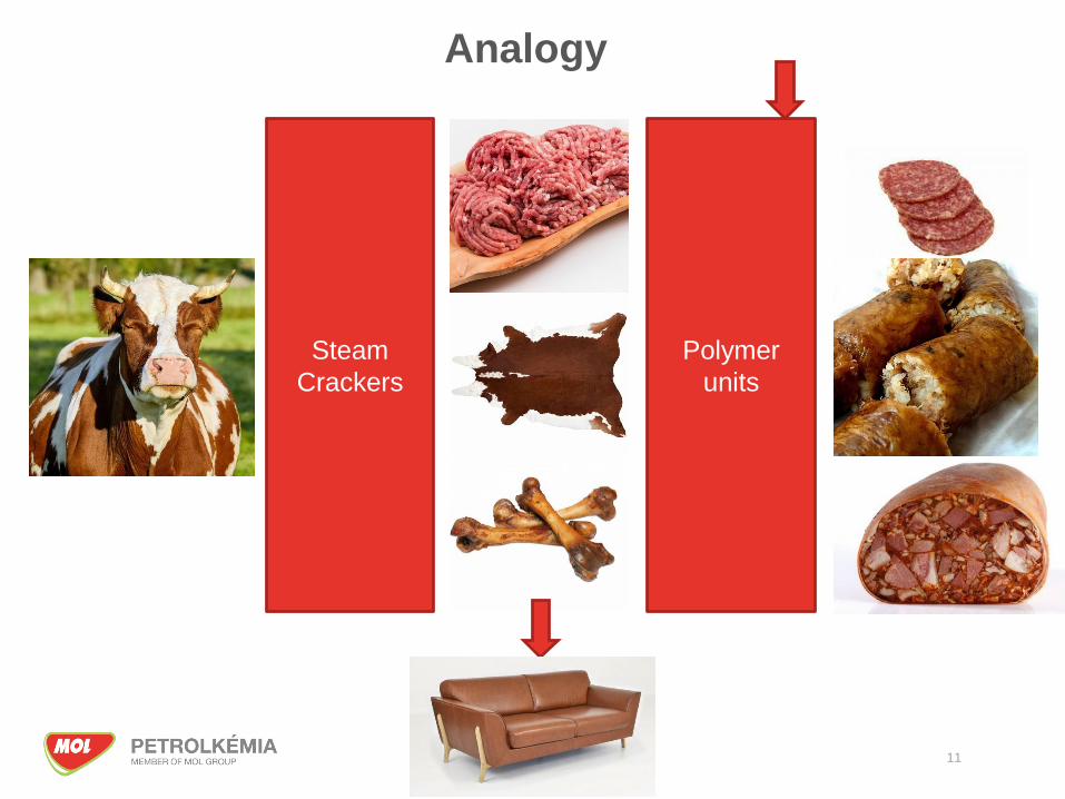
Steam
Crackers
Polymer
units
Analogy
11

Material and energy streams of a Steam cracker
Ethane (repyrolysis)
Propane (repyrolysis)
C4/C5 (repyrolysis)
Petchem Naphtha
Atmospheric Gasoil
LPG (Propane, Butane)
Steam
Cracker
Methane (fuel gas)
Steam
Electricity
Natural gas
Hydrogen
BT fraction
C8 fraction
C9+ fraction
Quenchoil
Polyol
DR
DR
DR
CTK
Ethylene
Propylene
Polyethylene units
Polypropylene units
12
13
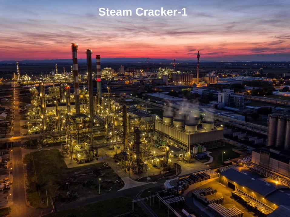
Steam Cracker-1
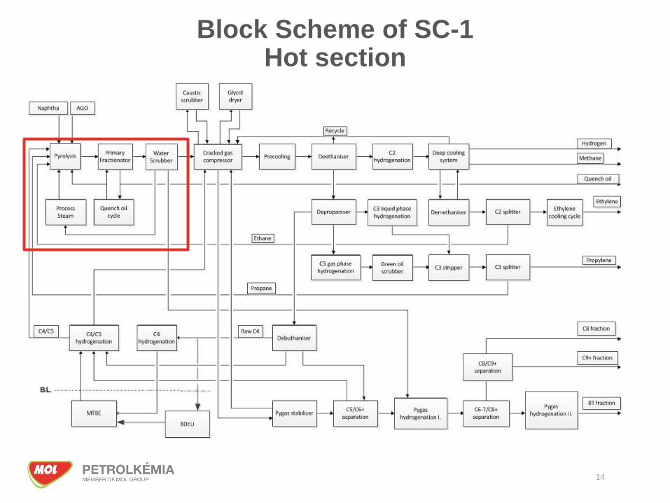
Block Scheme of SC-1Hot section
14

SteamCracker-2 furnaces
15
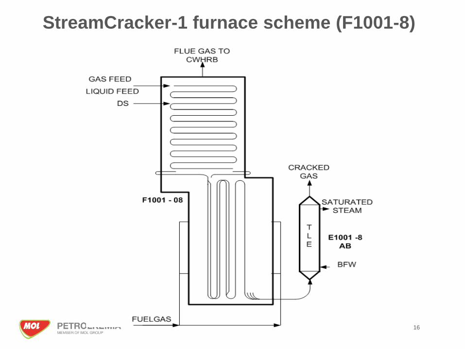
StreamCracker-1 furnace scheme (F1001-8)
16
17
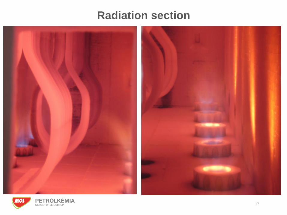
Radiation section

18
Pyrolitic parameters
COT Temperature: 800 – 860 °C
Outlet pressure: 0,3-0,6 barg
Propylene/ethylene ratio= 0,45 – 0,6
Steam/hydrocarbon ratio= 0,4 – 0,8
Residence time: 0,1 – 0,5 sec
Furnace runlength (between decokings): 30-80 days
For SC-2 max load 4oo3 furnaces are needed
For SC-1 max load 9oo11 furnaces are needed

19
The problem of coking
During operation a coke layer formed in the radiant tubes
At a given Tube Metal Temperature (TMT) the radiant tubesand has to be decoked
Coke formation is catalysed by the Ni present in tube metal
Sulfur is used to deactivate the Ni and retard coke formation
Sulfur is dosed in form of DMDS that is decompose in theradiant zone and connect to the Ni, forms NiS

Oil and water quenching
20

21
SteamCracker-2
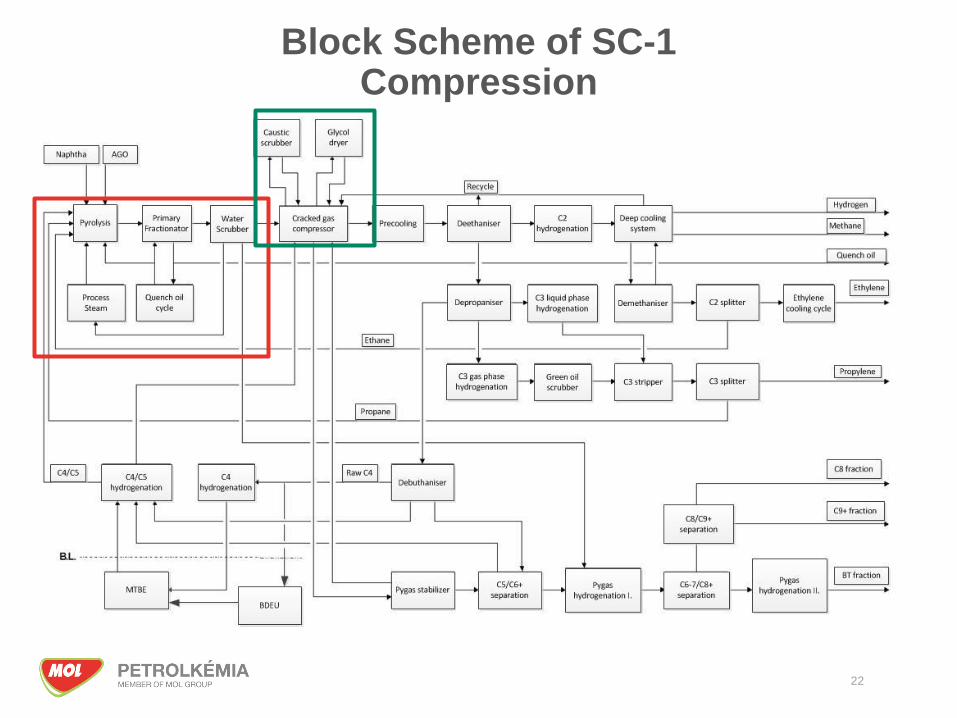
Block Scheme of SC-1Compression
22

Cracked gas compression
The compression of cracked gas takes place in a five stage centrifugal turbo compressor
Steam turbine driven
The water and the higher hydrocarbons are condensed in the interstage coolers and collected separately in the knockout drums
Caustic scrubber, Glycol (SC1)/molecular sieve (SC2)
Suction pressure: 0,5 bar(g)
Discharge pressure: • SC-1: 32 bar(g)
• SC-2: 36 bar(g)
23

24
Cracked gas compressor – Steamcracker-2
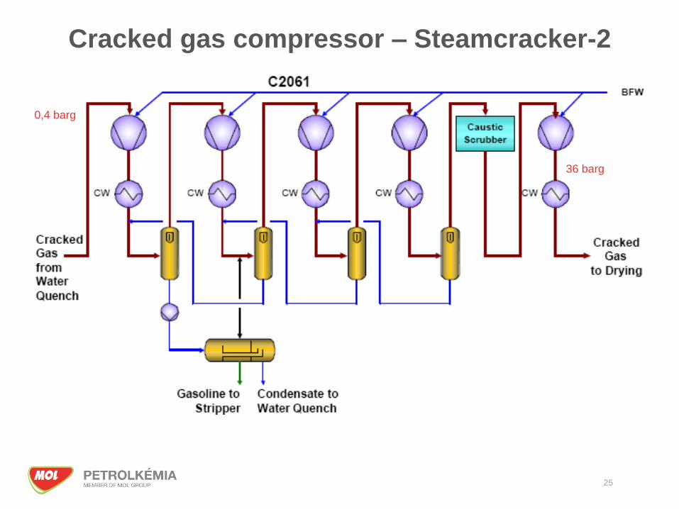
25
Cracked gas compressor – Steamcracker-2
0,4 barg
36 barg

Block Scheme of SC-1Cold section
26
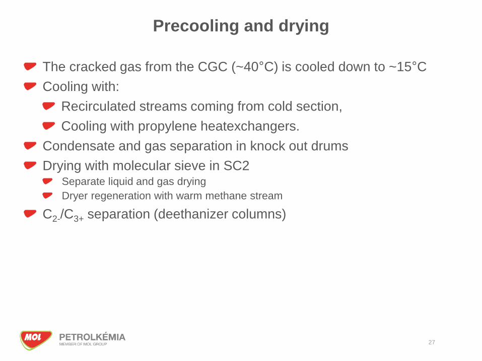
Precooling and drying
The cracked gas from the CGC (~40°C) is cooled down to ~15°C
Cooling with:
Recirculated streams coming from cold section,
Cooling with propylene heatexchangers.
Condensate and gas separation in knock out drums
Drying with molecular sieve in SC2Separate liquid and gas drying
Dryer regeneration with warm methane stream
C2-/C3+ separation (deethanizer columns)
27
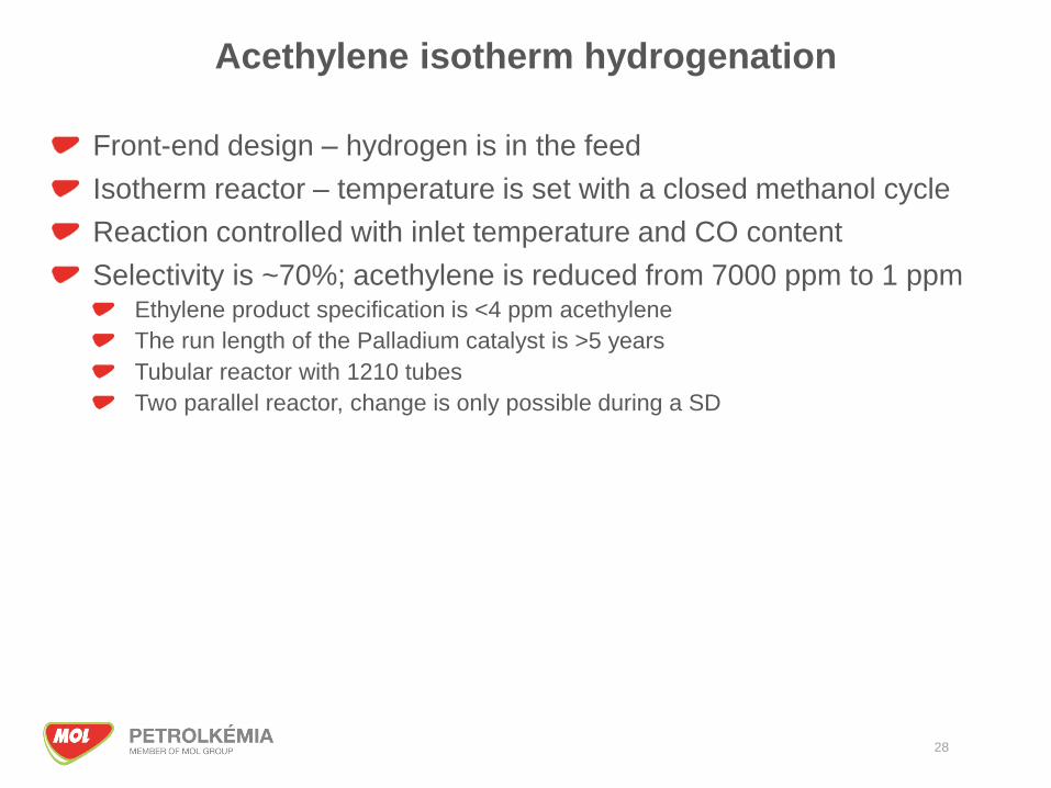
Acethylene isotherm hydrogenation
28
Front-end design – hydrogen is in the feed
Isotherm reactor – temperature is set with a closed methanol cycle
Reaction controlled with inlet temperature and CO content
Selectivity is ~70%; acethylene is reduced from 7000 ppm to 1 ppmEthylene product specification is <4 ppm acethylene
The run length of the Palladium catalyst is >5 years
Tubular reactor with 1210 tubes
Two parallel reactor, change is only possible during a SD
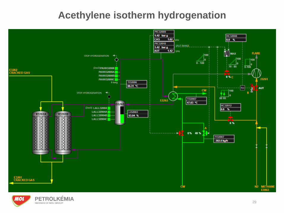
Acethylene isotherm hydrogenation
29
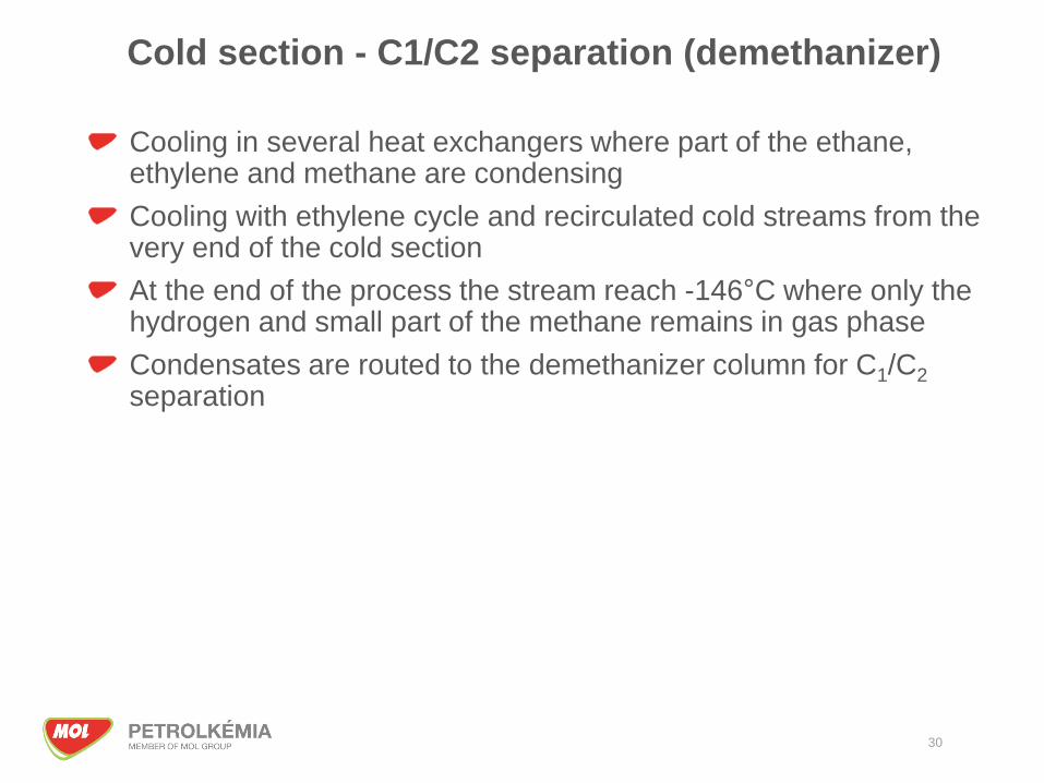
Cold section - C1/C2 separation (demethanizer)
Cooling in several heat exchangers where part of the ethane, ethylene and methane are condensing
Cooling with ethylene cycle and recirculated cold streams from the very end of the cold section
At the end of the process the stream reach -146°C where only the hydrogen and small part of the methane remains in gas phase
Condensates are routed to the demethanizer column for C1/C2
separation
30
31

C1/C2 separation
32

Ethylene cooling cycle
Four stage centrifugal compressor
Powered by steam turbine
Open cycle:
The compressor produces the reflux of the column
Supply the ethylene heat exchangers with liquid ethylene,
Supply the polyethylene plants.
33

Ethylene compressor
34

35
Ethylene cycle

Block Scheme of SC-1Propylene line
36
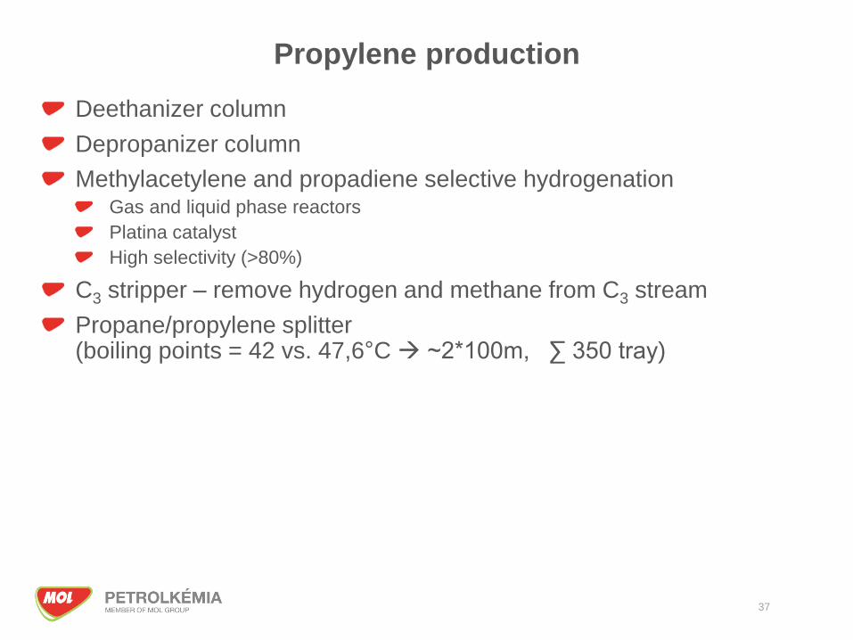
Propylene production
Deethanizer column
Depropanizer column
Methylacetylene and propadiene selective hydrogenationGas and liquid phase reactors
Platina catalyst
High selectivity (>80%)
C3 stripper – remove hydrogen and methane from C3 stream
Propane/propylene splitter(boiling points = 42 vs. 47,6°C → ~2*100m, ∑ 350 tray)
37
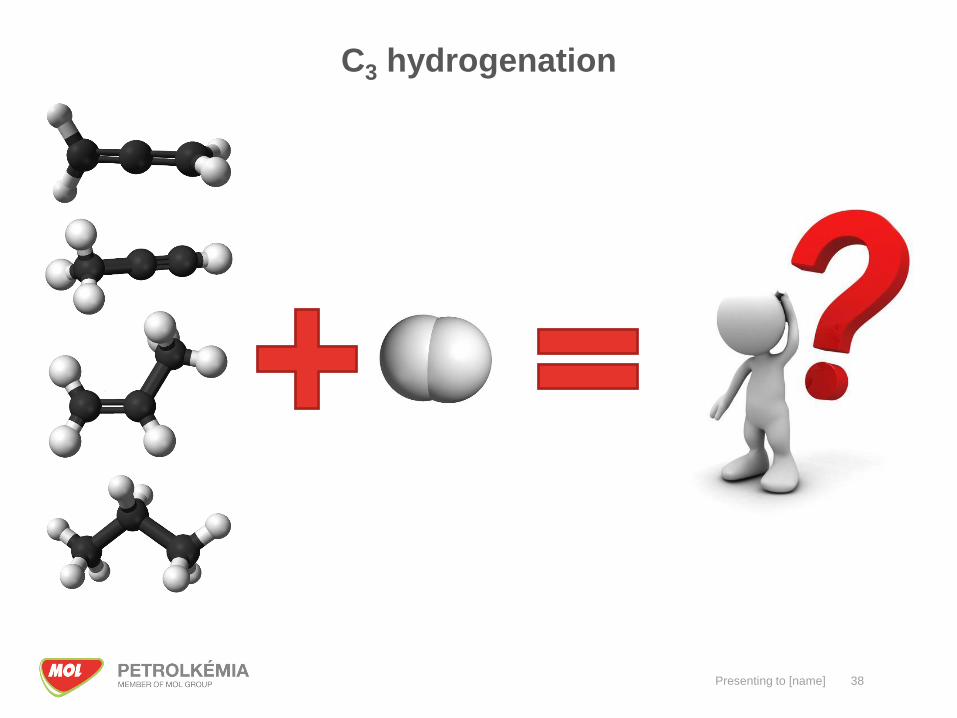
C3 hydrogenation
Presenting to [name] 38

Block Scheme of SC-1C4 and pygas section
39

40
C3/C4+ separation (depropanizer)
C4/C5+ separation (debuthanizer) RawC4 to BDEU
C5/C6+ separation (depenthanizer)
C4 selective hydrogenation MTBE feed
C4/C5 total hydrogenation Repyrolysis
Pygas 1st stage hydrogenation
C6-C7/C8+ separation
Pygas 2nd stage hydrogenation BT product
C8/C9+ separation C8, C9+ product
C4/C5 and pygas hydrogenation

Pygas hydrogenation
Remove of unsaturated molecules of the Pygas stream and separation for marketable products:
BT fraction aromatic unit feed
C8 fraction Gasoline mixing component
C9+ fraction Bunker mixing component or cutter stock
41
42
Steam and condensate
Boiler
Boiler feed water preparation
Fuel gas
Catalyst regeneration
Waste eater treatment
Flare
Cooling water
Utility systems
Presenting to [name] 43
Thank you for your attention!