steam gen
TRANSCRIPT

8/7/2019 Steam Gen
http://slidepdf.com/reader/full/steam-gen 1/13
Steam Generator Degradation and Its Impact onContinued Operation of Pressurized Water Reactors
in the United States
byKenneth Chuck Wade
Introduction
Nu cle ar p o wer is t h e s eco n d la rg es t s ou r ce fo r
electricity generation in the United States, accounting
for more than one-fifth of total util ity-generated
electricity in 1994. Currently, 109 nuclear units are
licensed in the United States, representing a total
capacity of 99 gigawatts electric.1 Of the 109 units, 72
are pressurized light-water reactors (PWR) and 37 are
boiling-w ater reactors (BWR).2 Since nuclear power
began to be widely used for commercial purposes in
the 1960’s, unit operators have experienced a variety of
problems with major components. Although many of
the problems have diminished considerably, those
associated with PWR steam generators persist. As of
December 31, 1994, 35 steam generators had been
replaced in 12 of the 72 operating PWR’s, and 3 units
had been shut down prematurely, due primarily (or
partially) to degradation of their steam generators:Portland General Electric’s Trojan unit, located in
Prescott, Oregon, in 1992; Southern California Edison’s
San Onofre 1, located in San Clemente, CA, in 1992;
and Sacramento Mun icipal Utility District’s Rancho
Seco unit in 1989.
In the coming years, operators of PWR’s in the United
States with degraded steam generators will have to
decide whether to make annu al repairs (with eventual
derating likely), replace the generators, or shut the
plants dow n pr ematurely. To understand the issues and
decisions utility managers face, th is article examines
problems encountered at steam generators over the pastfew decades and identifies some of the remedies that
utili ty operators and the nuclear community have
employed, including operational changes, maintenance,
repairs, and steam generator replacement. The technical,
regu latory, and finan cial factors associated with steam
generator maintenance and replacement are also iden-
tified. In addition, a list of 23 units are identified as
potential candidates for steam generator replacement or
shutdown.
Pressurized Light-Water Reactor
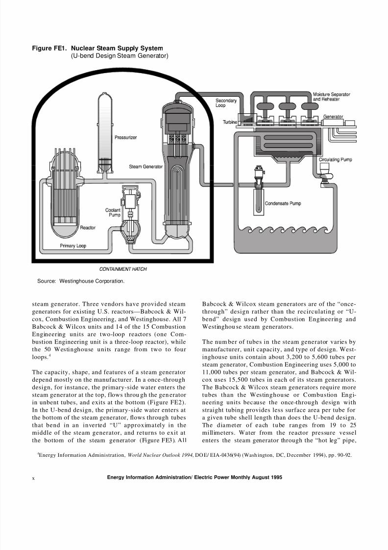
In a PWR, heated water is carried out of the reactor
core by the primary loop to the steam generator, wh ere
the heat is transferred to the secondary loop (Figure
FE1). The pressure in the reactor and the primary loop
is about 2,250 p ounds per square inch, w hich permits
t h e wa t er t o b e h e at ed t o a t em p e ra tu r e o f 6 00° F
without boiling.3 Tubes containing p rimary-loop water,
wh ich is radioactive, heat u p the second ary-loop w ater
and convert it into steam. This process cools the
primary-loop water somewhat, to about 550° F. The
primary-loop w ater is then pum ped th rough the reactoragain, reheating the water and starting the cycle over.
In the secondary loop, meanwhile, steam leaves the
steam generator at a temperature of about 500° F and
at a pressure well below that of the primary loop. It
exits at the top of the steam generator through moisture
separators, steam d ryers, and other systems, and is then
piped to a turbine generator, w here i t expands and
spins a turbine to generate electricity. The steam
leaving the turbine, which is now lower in pressure
than when it leaves the steam generator, is converted
back into water in the condenser and returned to the
steam generator to begin the secondary cycle again.U.S. PWR’s have two, three, or four steam generators
and are called two-loop, three-loop, or four-loop un its,
respectively. Generally, the plan ts with larger capacities
have m ore loops in order to accommod ate a larger total
heat transfer surface area while limiting the size of each
1Energy Information Ad ministration, Form EIA-860, “Ann ual Generator Report.”2Two types of reactors operate in the United States: PWR’s and BWR’s. Only PWR’s have steam generators.3“The Nuclear Power Plant,” a brochure published by B&W Nuclear Technologies, Lynchburg, Virginia, p. 2.
Energy Information Administration/ Electric Power Monthly August 1995 ix
8/7/2019 Steam Gen
http://slidepdf.com/reader/full/steam-gen 2/13
Figure FE1. Nuclear Steam Supply System(U-bend Design Steam Generator)
Source: Westinghouse Corporation.
steam generator. Three vendors have provided steam
generators for existing U.S. reactors—Babcock & Wil-
cox, Combustion Engineering, and Westinghouse. All 7
Babcock & Wilcox units and 14 of the 15 Combustion
Engineering units are two-loop reactors (one Com-
bustion Engineering unit is a three-loop reactor), while
the 50 Westinghouse units range from two to four
loops.4
The capacity, shape, and features of a steam generator
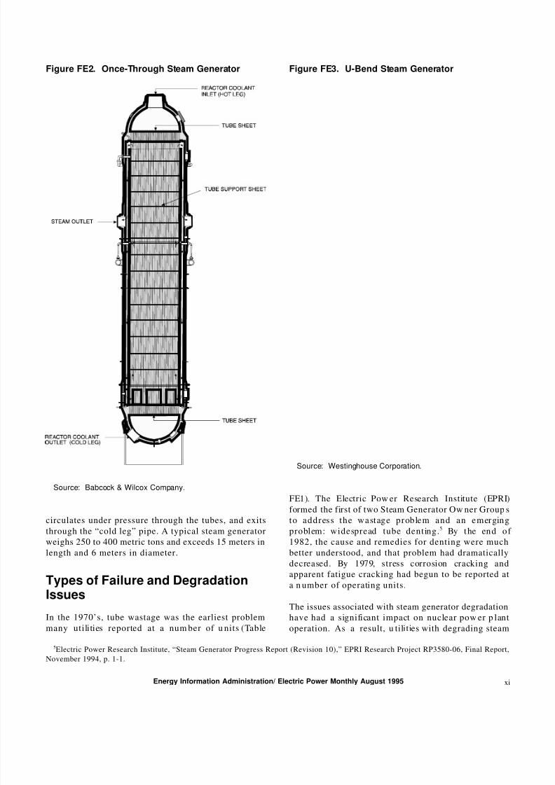
depend mostly on the manufacturer. In a once-through
design, for instance, the primary-side water enters thesteam generator at the top, flows throu gh the gen erator
in unbent tubes, and exits at the bottom (Figure FE2).
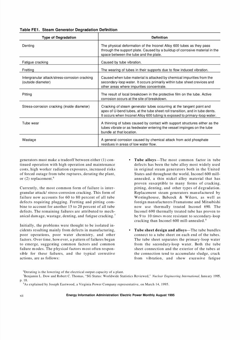
In the U-bend design, the primary-side water enters at
the bottom of the steam generator, flows through tubes
that bend in an inverted “U” approximately in the
middle of the steam generator, and returns to exit at
the bottom of the steam generator (Figure FE3). All
Babcock & Wilcox steam generators are of the “once-
through” design rather than the recirculating or “U-
bend” design used by Combustion Engineering and
Westinghou se steam generators.
The num ber of tubes in the steam generator varies by
manufacturer, unit capacity, and type of design. West-
inghouse units contain about 3,200 to 5,600 tubes per
steam generator, Combustion Engineering uses 5,000 to
11,000 tubes per steam generator, and Babcock & Wil-
cox uses 15,500 tubes in each of its steam generators.
The Babcock & Wilcox steam generators require moretubes than the Westinghouse or Combustion Engi-
neering units because the once-through design with
straight tubing provides less surface area per tube for
a given tube shell length than does the U-bend design.
Th e d ia m et er o f e a ch t u be r an g es fr om 19 t o 25
millimeters. Water from the reactor pressure vessel
enters the steam generator through the “hot leg” pipe,
4Energy Information Administration, World Nuclear Outlook 1994, DO E/ EIA-0436(94) (Wash ington, DC, D ecember 1994), pp . 90-92.
Energy Information Administration/ Electric Power Monthly August 1995x
8/7/2019 Steam Gen
http://slidepdf.com/reader/full/steam-gen 3/13
Figure FE2. Once-Through Steam Generator
Source: Babcock & Wilcox Company.
circulates under pressure through the tubes, and exits
through the “cold leg” pipe. A typical steam generator
weighs 250 to 400 metric tons and exceeds 15 meters in
length and 6 meters in diameter.
Types of Failure and DegradationIssues
In the 1970’s, tube wastage was the earliest problem
many utilities reported at a num ber of u nits (Table
Figure FE3. U-Bend Steam Generator
Source: Westinghouse Corporation.
FE1). The Electric Pow er Research Institute (EPRI)
formed the first of two Steam Generator Ow ner Group s
t o a d d r es s t h e wa st ag e p r ob le m a n d a n e m er gin g
problem: widespread tube denting.5 By t he en d o f
1982, the cause and remedies for denting were much
better understood, and that problem had dramaticallydecreased. By 1979, stress corrosion cracking and
apparent fatigue cracking had begun to be reported at
a n umber of operating units.
The issues associated with steam generator degradation
have had a significant impact on nuclear pow er p lant
operation. As a result, u tilities with degrading steam
5Electric Power Research Institute, “Steam Generator Progress Report (Revision 10),” EPRI Research Project RP3580-06, Final Report,
November 1994, p. 1-1.
Energy Information Administration/ Electric Power Monthly August 1995 xi
8/7/2019 Steam Gen
http://slidepdf.com/reader/full/steam-gen 4/13
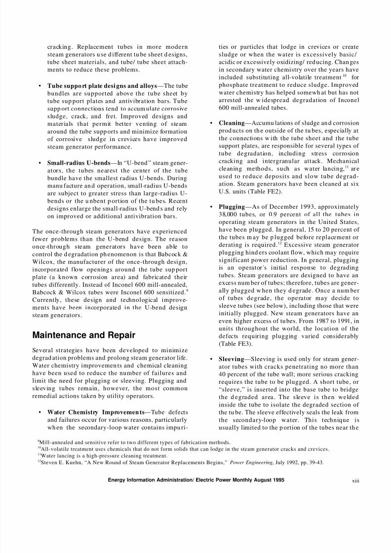
Table FE1. Steam Generator Degradation Definition
Type of Degradation Definition
Denting The physical deformation of the Inconel Alloy 600 tubes as they pass
through the support plate. Caused by a buildup of corrosive material in the
space between the tube and the plate.
Fatigue cracking Caused by tube vibration.
Fretting The wearing of tubes in their supports due to flow induced vibration.
Intergranular attack/stress-corrosion cracking
(outside diameter)
Caused when tube material is attacked by chemical impurities from the
secondary-loop water. It occurs primarily within tube sheet crevices and
other areas where impurities concentrate.
Pitting The result of local breakdown in the protective film on the tube. Active
corrosion occurs at the site of breakdown.
Stress-corrosion cracking (inside diameter) Cracking of steam generator tubes occurring at the tangent point and
apex of U-bend tubes, at the tube sheet roll transition, and in tube dents.
It occurs when Inconel Alloy 600 tubing is exposed to primary-loop water.
Tube wear A thinning of tubes caused by contact with support structures either as the
tubes vibrate or as feedwater entering the vessel impinges on the tube
bundle at that location.
Wastage A general corrosion caused by chemical attack from acid phosphate
residues in areas of low water flow.
generators must make a tradeoff between either (1) con-
tinued operation with high operation and maintenance
costs, high worker radiation exposures, increased risks
of forced outage from tube rup tures, derating the plant,
or (2) replacement.6
Currently, the most common form of failure is inter-
granular attack/ stress-corrosion cracking. This form of
failure now accounts for 60 to 80 percent of all tube
defects requiring plugging. Fretting and pitting com-
bine to account for another 15 to 20 percent of all tube
defects. The remaining failures are attributed to mech-
anical dam age, wastage, denting, and fatigue cracking.7
Initially, the problems were thought to be isolated in-
cidents resulting mainly from defects in manufacturing,
poor operations, poor water chemistry, and other
factors. Over time, how ever, a p attern of failures beganto emerge, suggesting common factors and common
failure m odes. The p hysical factors m ost often respon-
sible for these failures, and the typical corrective
actions, are as follows:
• Tube alloys—The most common factor in tube
defects has been the tube alloy most widely used
in original steam generators both in the United
States and throughout the world, Inconel 600 mill-
annealed, a thin nickel alloy material that hasproven susceptible to many forms of cracking,
pitting, denting, and other types of d egradation.
Replacement steam generators man ufactured by
Westinghouse, Babcock & Wilcox, as well as
foreign man ufacturers Framatome and Mitsubishi
now use thermally treated Inconel 690. The
Inconel 690 thermally treated tube has proven to
be 9 to 10 times m ore resistant to secondary-loop
cracking than Inconel 600 mill-annealed.8
• Tube sheet design and alloys—The tube bundles
connect to a tube sheet on each end of the tubes.
The tube sheet separates the primary-loop waterfrom the secondary-loop water. Both the tube
sheet connection and the exterior of the tubes at
the connection tend to accumulate sludge, crack
fr om v ib ra tio n , a n d s ho w e xce ss iv e fa tig u e
6Derating is the lowering of the electrical output capacity of a plant.7Benjamin L. Dow and Robert C. Thomas, “SG Status: Worldwide Statistics Reviewed,” Nuclear Engineering International, Janu ary 1995,
p. 18.8As explained by Joseph Eastwood, a Virginia Power Company representative, on March 14, 1995.
Energy Information Administration/ Electric Power Monthly August 1995xii
8/7/2019 Steam Gen
http://slidepdf.com/reader/full/steam-gen 5/13
cracking. Replacement tubes in more modern
steam generators u se d ifferent tu be sheet d esigns,
tube sheet materials, and tube/ tube sheet attach-
ments to reduce these problems.
• Tube suppo rt plate desi gns and alloys —The tube
bundles are supported above the tube sheet by
tube sup port plates and antivibration bars. Tube
supp ort connections tend to accum ulate corrosive
sludge, crack, and fret. Improved designs and
materials that permit better venting of steam
around the tube supp orts and minimize formation
of corrosive sludge in crevices have improved
steam generator performance.
• Small-radius U-bends—In “U-bend ” steam gener-
ators, the tubes nearest the center of the tube
bundle have the smallest radius U-bends. During
manu facture an d operation, small-radius U-bends
are subject to greater stress than large-radius U-bends or the u nbent p ortion of the tu bes. Recent
designs enlarge the small-radius U-bend s and rely
on improved or additional antivibration bars.
The once-through steam generators have experienced
fewer problems than the U-bend design. The reason
once-through steam generators have been able to
control the d egradation ph enomenon is that Babcock &
Wilcox, the manufacturer of the once-through design,
incorporated flow openings around the tube sup port
plate (a known corrosion area) and fabricated their
tubes differently. Instead of Inconel 600 mill-annealed,
Babcock & Wilcox tubes were Inconel 600 sensitized.9
Currently, these design and technological improve-
ments have been incorporated in the U-bend design
steam generators.
Maintenance and Repair
Several strategies have been developed to minimize
degrad ation problems and prolong steam generator life.
Water chemistry improvemen ts and chemical cleaning
have been used to reduce the number of failures and
limit the need for plugging or sleeving. Plugging and
sleeving tubes remain, however, the most commonremedial actions taken by utility operators.
• Water Chemistry Improvemen ts—Tube defects
and failures occur for various reasons, particularly
wh en the secondary-loop water contains impu ri-
ties or particles that lodge in crevices or create
sludge or when the water is excessively basic/
acidic or excessively oxidizing/ red ucing. Chan ges
in secondary water chemistry over the years have
included substituting all-volatile treatment10 for
phosphate treatment to reduce sludge. Improved
water chemistry has helped somewh at but has not
arrested the w idespread degradation of Inconel
600 mill-annealed tubes.
• Cleaning—Accumu lations of sludge an d corrosion
prod ucts on th e outside of the tu bes, especially at
the connections w ith the tube sheet and the tube
support plates, are responsible for several types of
tube degradation, including stress corrosion
cracking and intergranular attack. Mechanical
cleaning methods, such as water lancing,11 ar e
used to reduce deposits and slow tube degrad-
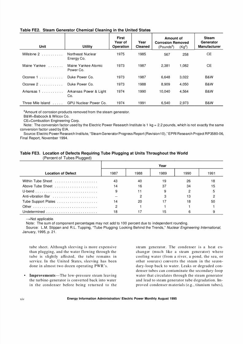
ation. Steam generators have been cleaned at six
U.S. units (Table FE2).
• Plugging—As of December 1993, approximately
38,000 tubes, or 0.9 percent of all the tubes in
operating steam generators in the United States,
have been plugged. In general, 15 to 20 percent of
the tubes m ay be p lugged before replacement or
derating is required.12 Excessive steam generator
plugging hind ers coolant flow, which may require
significant power reduction. In general, plugging
is an operator’s initial response to degrading
tubes. Steam generators are designed to have an
excess num ber of tubes; therefore, tubes are gener-
ally plugged w hen they d egrade. Once a num berof tubes degrade, the operator may decide to
sleeve tubes (see below), including those that were
initially plugged. New steam generators have an
even higher excess of tu bes. From 1987 to 1991, in
units throughout the world, the location of the
defects requiring plugging varied considerably
(Table FE3).
• Sleeving—Sleeving is used only for steam gener-
ator tubes with cracks penetrating no more than
40 percent of the tube wall; more serious cracking
requires the tube to be plugged. A short tube, or
“sleeve,” is inserted into the base tube to bridgethe d egraded area. The sleeve is then welded
inside the tube to isolate the degraded section of
the tu be. The sleeve effectively seals the leak from
the secondary-loop water. This technique is
usually limited to the p ortion of the tubes near th e
9Mill-annealed and sensitive refer to two different types of fabrication methods.10All-volatile treatment uses chemicals that do not form solids that can lodge in the steam generator cracks and crevices.11Water lancing is a high-pressure cleaning treatment.12Steven E. Kuehn, “A New Round of Steam Generator Replacements Begins,” Power Engineering, July 1992, pp. 39-43.
Energy Information Administration/ Electric Power Monthly August 1995 xiii
8/7/2019 Steam Gen
http://slidepdf.com/reader/full/steam-gen 6/13
Table FE2. Steam Generator Chemical Cleaning in the United States
Unit Utility
First
Year of
Operation
Year
Cleaned
Amount of
Corrosion Removed
(Poundsa) (Kga)
Steam
Generator
Manufacturer
Millstone 2 . . . . . . . . . . Northeast Nuclear
Energy Co.
1975 1985 567 258 CE
Maine Yankee . . . . . . . Maine Yankee AtomicPower Co.
1973 1987 2,381 1,082 CE
Oconee 1 . . . . . . . . . . . Duke Power Co. 1973 1987 6,648 3,022 B&W
Oconee 2 . . . . . . . . . . . Duke Power Co. 1973 1988 8,909 4,050 B&W
Arkansas 1 . . . . . . . . . . Arkansas Power & LightCo.
1974 1990 10,040 4,564 B&W
Three Mile Island . . . . . GPU Nuclear Power Co. 1974 1991 6,540 2,973 B&W
aAmount of corrosion products removed from the steam generator.B&W=Babcock & Wilcox Co.
CE=Combustion Engineering Corp.Note: The conversion factor used by the Electric Power Research Institute is 1 kg = 2.2 pounds, which is not exactly the same
conversion factor used by EIA.Source: Electric Power Research Institute, “Steam Generator Progress Report (Revision10),” EPRI Research Project RP3580-06,
Final Report, November 1994.
Table FE3. Location of Defects Requiring Tube Plugging at Units Throughout the World(Percent of Tubes Plugged)
Location of Defect
Year
1987 1988 1989 1990 1991
Within Tube Sheet . . . . . . . . . . . . . . . . . . . . 43 40 19 26 18Above Tube Sheet . . . . . . . . . . . . . . . . . . . . 14 16 37 34 15
U-bend . . . . . . . . . . . . . . . . . . . . . . . . . . . . . 9 11 9 2 5
Anti-vibration Bar . . . . . . . . . . . . . . . . . . . . . -- 2 3 13 2
Tube Support Plates . . . . . . . . . . . . . . . . . . . 14 20 17 18 50
Other . . . . . . . . . . . . . . . . . . . . . . . . . . . . . . 2 1 1 1 1
Undetermined . . . . . . . . . . . . . . . . . . . . . . . . 18 17 15 6 9
--=Not applicable.Note: The sum of component percentages may not add to 100 percent due to independent rounding.Source: L.M. Stippan and R.L. Tupping, “Tube Plugging: Looking Behind the Trends,” Nuclear Engineering International ,
January, 1995, p. 21.
tube sheet. Although sleeving is more expensive
than plugging, and the water flowing through the
tube is slightly affected, the tube remains in
service. In the United States, sleeving has been
done in almost two dozen operating PWR’s.
• Improvements —The low-pressure steam leaving
the turbine-generator is converted back into water
in the condenser before being returned to the
steam generator. The condenser is a heat ex-
changer (much like a steam generator) where
cooling water (from a river, a pond, the sea, or
other sources) converts the steam in the secon-
dary-loop back to water. Leaks or degraded con-
denser tubes can contaminate the secondary-loop
water that circulates through the steam generator
and lead to steam generator tube d egradation. Im-
proved condenser m aterials (e.g., titanium tubes),
Energy Information Administration/ Electric Power Monthly August 1995xiv

8/7/2019 Steam Gen
http://slidepdf.com/reader/full/steam-gen 7/13
better leak detection devices, and better water
chemistry minimize condenser-related problems
and associated steam generator problems.
Even with condenser improvements,13 water chemistry
improvements, inspection and cleaning programs,
operational changes, and other actions, p roblems atsteam generators are continuing. Recently, there have
been reports of circumferential cracks14 near the tube
sheet that went u nd etected in stand ard inspections, but
were found using m ore sophisticated tube inspection
equipment. Although circumferential cracks are not a
new phenomenon, new tube inspection devices have
shown that the cracks may be more numerous than
initially thought. EPRI reports that 28 plants have
reported find ing circum ferential cracks near the top of
the tube sheet since 1987.
In 1994, circumferential cracks were d iscovered in m ore
than half the tubes at the top of the tube sheet in thesteam generators at the Maine Yankee nuclear plant.
The utility, Maine Yankee Atomic Power Company, is
considering sleeving all 17,109 tubes in the three-loop
reactor. The repair is estimated to cost $64 million, not
including the cost of replacement power. Due to the
industry’s latest findings, the Nuclear Regulatory Com-
mission is asking each PWR operator to prove that, like
Maine Yankee, it is adequately inspecting its steam
generators for these cracks. Working to address these
problems are the individu al utilities and vendors and
several industry group s, such as the Steam Generator
Re p la ce m en t Gro u p , t h e EPRI St ea m Gen er at or
Strategic Management Project (successor to the EPRI
Steam Generator Ow ners Group), the Westinghouse
Own er s Gro u p , a n d t h e Com b u st io n En g in e er in g
Owners Group.
Steam Generator Replacement
When a utility decides to replace its steam generators,
it must go through extensive planning efforts that
include examining the extent of damage to the steam
generators, estimating the length of time required to
replace the steam generators, deciding whether a partial
or complete steam generator replacement is needed,and determining the cost associated with replacement.
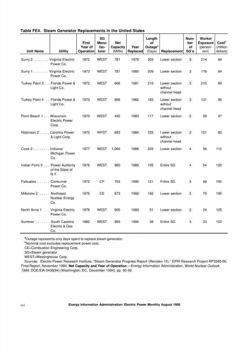
A total of 12 U.S. un its have rep laced steam generators
(Table FE4), all of w hich are of the U-bend design.
Two techniques h ave been utilized to replace steam
generators:the p ipe-cut and chann el-head-cut m ethods.
In the pipe-cut method, the entire steam generator is
removed from the reactor coolant system by cutting the
hot and cold leg primary piping ad jacent to the channel
head of the steam generator. Replacement steam gen-
e ra to rs o r r ep la ce m en t p o rt io n s a re in s ta lle d b y
reconnecting the p rimary p iping to complete the repair
operation. If the reactor containment hatch is large
enough, the entire steam generator assembly can be
removed intact (after disconnecting the feedwater and
steam nozzle) and replaced. This not only shortens
replacement time and lowers worker exposure, but also
reduces costs as compared to cutting a hole in the
containment hatch.
In the channel-head-cut technique, the steam generator
is separated by cutting the channel head just below the
tube sheet. This leaves the lower primary p iping in
place and simplifies fitting the steam generator back into place. The upper portion of the steam generator
can be replaced in its entirety or the upper part of the
steam generator can be cut and refurbished in the con-
tainment building.
Both steam generator ou tage time and worker rad iation
exposure (person-rem per steam generator) during
steam generator replacement have dropped consider-
ably (Table FE4). The m ost recent r eplacement, at South
Carolina Electric & Gas Comp any’s Summ er u nit, took
38 days from the time the reactor coolant system piping
was severed until the secondary-side piping was pres-
surized to 1,500 pounds for testing. The world recordfor a steam generator replacement, set in France in 1994
a t Gra ve lin es Un it 1, is 37 d a y s.15 During steam
generator replacements, as well as other operational
activities (e.g., refueling and maintenance), th e NRC
requires each utility to keep exposure “as low as
reasonably achievable.” Total worker exposure for the
Summer replacement was 33 person-rem. The lowest
worker exposure rate in the United States w as 24
person-rem at North Anna 1, the replacement prior to
the Summer unit replacement.
The only significant deviation from the down ward
trend in outage duration and worker exposure was ther ep la ce m en t a t t h e M ills to n e 2 u n it , lo ca te d in
Waterford, CT. The Millstone 2 situation was unusual
in that one of the cold leg pipes shifted as it was being
13The condenser is the unit where raw cooling water condenses the steam leaving the turbine. Improper condenser materials can
introduce contaminants, minerals, chemicals or other materials into the steam generator.14Circum ferential propa gating cracks are cracks occuring arou nd the perim eter of the tube in contrast to axial cracks, which prop agate
lengthwise on the tube.15“SCE&G Sets U.S. Steam Generator Replacement Record at Summer,” N ucleonics W eek , December 1, 1994, pp. 1-2.
Energy Information Administration/ Electric Power Monthly August 1995 xv
8/7/2019 Steam Gen
http://slidepdf.com/reader/full/steam-gen 8/13
Table FE4. Steam Generator Replacements in the United States
Unit Name Utility
First
Year of
Operation
SG
Manu-
fac-
turer
Net
Capacity(MWe)
Year
Replaced
Length
of
Outagea
(Days) Replacement
Num-
ber
of
SG’s
Worker
Exposure(person-
rem)
Costb
(milliondollars)
Surry 2 . . . . . . . . Virginia Electric
Power Co.
1972 WEST 781 1979 303 Lower section 3 214 94
Surry 1 . . . . . . . . Virginia Electric
Power Co.
1973 WEST 781 1980 209 Lower section 3 176 94
Turkey Point 3 . . Florida Power &
Light Co.
1972 WEST 666 1981 210 Lower section
without
channel head
3 215 90
Turkey Point 4 . . Florida Power &
Light Co.
1973 WEST 666 1982 183 Lower section
without
channel head
3 131 90
Point Beach 1 . . . Wisconsin
Electric Power
Corp.
1970 WEST 492 1983 117 Lower section 2 59 47
Robinson 2 . . . . . Carolina Power
& Light Corp.
1970 WEST 683 1984 225 Lower section
without
channel head
3 121 85
Cook 2 . . . . . . . . Indiana/
Michigan Power
Co.
1977 WEST 1,060 1988 202 Lower section 4 56 112
Indian Point 3 . . . Power Authority
of the State of
N.Y.
1976 WEST 980 1989 105 Entire SG 4 54 120
Palisades . . . . . . Consumer
Power Co.
1972 CE 755 1990 121 Entire SG 3 49 100
Millstone 2 . . . . . Northeast
Nuclear Energy
Co.
1975 CE 873 1992 192 Lower section 3 70 190
North Anna 1 . . . Virginia Electric
Power Co.
1978 WEST 900 1993 51 Lower section 3 24 125
Summer . . . . . . . South Carolina
Electric & Gas
Co.
1982 WEST 885 1994 38 Entire SG 3 33 153
aOutage represents only days spent to replace steam generator.bNominal cost excludes replacement power cost.
CE=Combustion Engineering Corp.
SG=Steam generator
WEST=Westinghouse Corp.
Sources: Electric Power Research Institute, “Steam Generator Progress Report (Revision 10),” EPRI Research Project RP3580-06,
Final Report, November 1994; Net Capacity and Year of Operation —Energy Information Administration, World Nuclear Outlook
1994 , DOE/EIA-0436(94) (Washington, DC, December 1994), pp. 90-92.
Energy Information Administration/ Electric Power Monthly August 1995xvi
8/7/2019 Steam Gen
http://slidepdf.com/reader/full/steam-gen 9/13
cut. The shift, which occurred despite pipe restraints,
relieved stresses the pipe developed du ring original
installation and operations. Because of the shift, the
Northeast Nuclear Energy Company conducted an
extensive examination and analysis of pipe stress and
alignment. Analyzing and realigning the pipes add ed
41 d a y s t o t h e p r oce ss . Ad d it io n al we ld in g a n d
radiographic inspections took another 12 days.
Costs and Benefits of SteamGenerator Replacement
Replacement Costs
Replacement of a steam generator is an economic
decision. A steam generator w ith excessive tu be d egra-
dation creates extra costs for reasons such as:
• Tube inspections and leakage monitoring• M ain t en a n ce a n d r ep a ir (e .g ., p lu g g in g a n d
sleeving)
• Water chemistry control
• Condenser inspection, maintenance, and moni-
toring
• Occupational radiation exposure
• Power derating due to plugging
• Potential for forced outages due to tube leaks or
ruptures.
An analysis of one case showed that, compared to
continuing with the existing equipment, installing a
new steam generator would reduce annual steam gen-
erator rep air costs by $3.4 million.16 As maintenance
costs increase an d derating becomes m ore likely, the
economics of steam generator replacement becomes
more attractive.
The cost to replace the steam generator varies signifi-
cantly depending on factors such as:
• The num ber of generators replaced at one time
• Whether the replacement is partial or total
• Whether the equipment hatch is large enough to
accommodate the entire unit
• The amount of free space in the containment area
to position the unit and the type of containment
facility where the steam generator is located
• Th e n u m b er o f p ip e s th a t m u s t b e cu t a n d t h e
number of cuts
• The requirements for radiation shielding
• The requirements for pipe support
• Any potential pipe shifting problems (such as at
Millstone 2).
The cost of a steam generator is $12 million to $20
million.17 The cost to replace a steam generator is
substantially more. Complete replacement at a three-
loop PWR in the United States over the past 2 years
cost between $125 million and $153 million (Table FE4),
or about $139 per kilowatt (kW) to $170 per kW for a
typical 900 MWe unit. South Carolina Electric & Gas
Co. (SCE&G) spent an estimated $153 million to replace
three steam generators at the 885 MWe Summer unit.18
Ten U.S. units are planning to replace steam generators,
according to formal ann ouncements or reports con-
cerning placement of steam generator orders (Table
FE5). Florida Power & Light expects to spend about
$170 million, excluding replacement pow er costs, to
replace two steam generators at St. Lucie 1 in 1997. 19
Duke Power expects to spend $437 million, excluding
replacement power costs, to replace steam generators at
three four-loop u nits (McGuire 1 and 2 and Catawba 1)
between 1995 and 1997.20 The expected cost to replace
the steam generators at the three-loop North Anna 2
unit is $140 million.21
Whether replacement power costs are added to the
steam generator replacement cost depends on whether
t h e r ep la ce m en t o ccu r s d u r in g a n o u ta ge a lr ea d y
required for a refueling or maintenance outage. Ordi-
narily, the steam generator replacement coincides with
a n o rm a l r efu e lin g o r m a in t en a n ce o u ta ge . If t h e
replacement is carried out during a scheduled outage,
the steam generator replacement activity is charged
only for the time it adds to the ou tage. Steam generator
replacement t imes in the United States have been
dropping sharply over the past 2 years and are now
less than 2 months (Table FE4).
16Rochester Gas and Electric Corp., “1992 Integrated Resource Plan,” June, 1992, App endix D, p. 5. The analysis concerns th e Robert
Ginna plant in Rochester, New York, which is scheduled for a steam generator replacement in 1996.17H. Hennicke, “The Steam Generator Replacement Comes of Age,” N uclear Engineering International, July 1991, pp. 23-26.18“SCE&G Set U.S. Steam Generator Replacement Record at Summer,” Nucleonics Week , December 1, 1994, p.2, and “SCE&G Returns
Summer to Service After Replacing Steam Generators,” N ucleonics W eek , December 22, 1994, p. 3.19“DE&S Steam Generator Replacement Team Gets Foothold in Growing Market,” N ucleonics W eek , October 27, 1994, p. 7.20“Duke Power Readies for Successive Steam Generator Change-Outs,” Nucleonics Week , October 27, 1994, p. 6.21“Duke Power Readies for Successive Steam Generator Change-Outs,” Nucleonics Week , October 27, 1994, p. 6.
Energy Information Administration/ Electric Power Monthly August 1995 xvii

8/7/2019 Steam Gen
http://slidepdf.com/reader/full/steam-gen 10/13
Table FE5. Planned Steam Generator Replacements in the United States
Plant Utility
SG
Alloy
SG
Manufac
-turer Loops
Net
Capacitya
(MWe)
First
Year of
Opera-
tion
Total
Tubes
Total
Plug-
ged
Per-
cent
Plug-
ged
Total
Sleevedb
Projected
Year of
Replace-
ment
Projected
Cost
(milliondollars)
North Anna 2 Virginia Electric
Power Co.
I-600
MA
WEST 3 887 1980 10,164 1,332 13.1 0 1995 140
Ginna . . . . . Rochester Gas& Electric Corp.
I-600MA
WEST 2 470 1969 6,520 483 7.4 1,953 1996 115
Catawba 1 . Duke PowerCo.
I-600MA
WEST 4 1,129 1985 18,696 1,480 7.9 183 1996 437c
McGuire 1 . Duke PowerCo.
I-600MA
WEST 4 1,129 1987 18,696 1,819 9.7 841 1996/1997 NA
McGuire 2 . Duke PowerCo.
I-600MA
WEST 4 1,129 1983 18,696 1,387 7.4 615 1996/1997 NA
Point Beach2 . . . . . . . .
WisconsinElectric PowerCo.
I-600MA
WEST 2 482 1973 6,520 622 9.5 3,895 1996/1997 120
St. Lucie 1 . Florida Power& Light Co.
I-600MA
CE 2 839 1976 17,038 1,818 10.7 0 1997 170
Zion 1 . . . . CommonwealthEdison Co.
I-600MA
WEST 4 1,040 1973 13,552 948 7.0 806 2001 NA
Braidwood 1 CommonwealthEdison Co.
I-600MA
WEST 4 1,090 1987 18,696 333 1.8 0 1998 470d
Byron 1 . . . CommonwealthEdison Co.
I-600MA
WEST 4 1,120 1985 18,696 847 4.5 0 1999 NA
aEnergy Information Administration (EIA), Form EIA-860, “Annual Electric Generator Report.”bA tube can be sleeved more than once, and plugged tubes may have been sleeved.c$437 million is the cost to replace the steam generators at Catawba 1, McGuire 1, and McGuire 2.d$470 million is the cost to replace the steam generators at Braidwood 1 and Byron 1.
CE=Combustion Engineering Corp.NA=Not available.I-600 MA=Inconel 600 mill-annealedSG=Steam Generator
WEST=Westinghouse Corp.Sources: Electric Power Research Institute, “Steam Generator Progress Report (Revision 10),” EPRI Research Project RP3580-06, Final Report,
November 1994; Net Capacity and Year of Operation —Energy Information Administration, World Nuclear Outlook 1994 , DOE/EIA-0436(94)
(Washington, DC, December 1994), pp. 90-92.
The cost of replacement p ower d epends on many fac-
t or s, in clu d i ng t h e a m o u n t o f p o we r t h at m u s t b e
replaced, the region of the United States sup plying the
replacement power, the time of year, and the length of
the replacement outage. In most of the United States,the cost of economy energy is roughly $20 to $30 per
megawatthour (MWh).2 2 2 3 The cost could, however,
be less if the utility has a significant amount of low-cost
baseload su rplus energy. Short-term firm p ower w ould
be available for no more than about $40 per MWh. 24
The output from an 900 MWe nuclear power plant at
100 percent capacity factor is 657,000 MWh per month.
At $40 per MWh, replacing the output from the p lant
would be about $26 m illion per month. Taking intoaccount the availability of economy energy at $20 per
MWh, and short-term firm power at $40 per MWh, the
a m ou n t o f n u c le ar o u tp u t t o b e r ep la ce d , a n d t h e
duration of the replacement, replacement power costs
22Economy energy is energy produced and supplied from a more economical source in a system, substituted for that being produced
or capable of being produced by a less economical source in another system.23“Utility Reports Show Sharp Decline for February in Florida Economy Market,” Power M arkets W eek, April 10, 1995, p. 5.24Federal Energ y Regulator y Com mission (FERC) Form 1 (1993), “Ann ual Repor t of Major Electric Utilities, Licensees, and O thers,” w as
used to calculate short-term firm purchase power.
Energy Information Administration/ Electric Power Monthly August 1995xviii
8/7/2019 Steam Gen
http://slidepdf.com/reader/full/steam-gen 11/13
are likely to range from $13 million to no more than
$30 million. If the replacement coincides with a
regularly schedu led ou tage, steam generator replace-
ment power costs and, therefore, total steam generator
costs, could be ap preciably lower.
Replacement BenefitsIn general, there are four benefits to replacing a nuclear
steam generator. The first benefit is avoiding, or at least
substantially red ucing, the p roblems associated with
tube degradation outlined earlier. The savings from
eliminating repeated tube p lugging, extra m aintenance
and inspection work, and so forth can be millions of
dollars per year. The savings from avoiding a forced
outage due to a tube rupture are difficult to quantify
but could certainly amount to tens of m illions of
dollars, depending on when in the operating cycle the
r u p tu r e o ccu r re d ; fo r e xa m p le , if a t u be r u p tu r es
immediately before a refueling outage the utility wouldbe able to conduct maintenance and repairs on the
steam generator during the refueling outage. Tube
ruptures also prompt intense scrutiny by the NRC and
probably ad ditional attention from State regulators and
the public. Thus, avoiding tube ruptures is of con-
siderable value beyond the direct costs of the forced
outage.
The second benefit is that the increased heat transfer
surface may allow an uprating in the electric output of
the unit.25 26 At the Summer station, SCE&G plans an
uprate of approximately 50 MWe (about 5 percent)following the 1996 refueling outage.27 The increased
num ber of tubes and the increased heat transfer surface
also expand the margin for future plugging, if neces-
sary.
The value of an uprating depends on the remaining
expected life of the generating unit. For example, the
value of a 50 MWe up rate of a good-performance plant,
that has 20 years of remaining life, is probably worth
tens of millions of dollars.
The third benefit is reduced occupational exposure afterreplacement.28 Prolonged operation with degraded
steam generators will ultimately increase radiation
exposure and extend refueling outages due to the in-
creasing need for extensive tube inspection and repair.
The fourth benefit is d eferred decommissioning. Pre-
mature shutdown creates two major decommissioning
problems. First, the decommissioning trust will not
h a ve h a d t h e t im e t o a ccu m u la te t h e fu ll a m ou n t
needed to pay for decommissioning. If a plant is shut
dow n 10 years prematurely, the decommissioning trust
is likely to lack at least three-quarters of its decom-
missioning total.29 Second, decommissioning requires
extensive planning m any years in advance of actual
decommissioning activity. Planning includes onsite
activities, waste disposal preparations, licensing, settle-
ment of State regulatory issues, replacement power
planning, and the like. Deferring these activities and
conducting the planning on a non-emergency basis has
significant value to a utility.
Finally, owners considering steam generator replace-ment will find the job easier to justify if they are also
considering license renewal, as a long license term
provides a lower per kWh cost for the replacement.
Outlook
Units with original steam generators incorporating the
Inconel 600 mill-annealed alloy tubing are almost
certain to face degradation problems. In 1993, the NRC
fo u n d “ n o e nd in s ig h t” t o s te am g en er at or t u be
cracking problems at plants operating with original
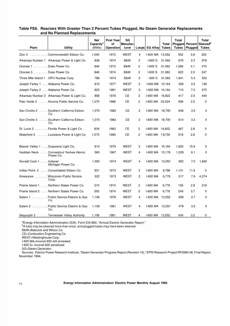
steam generators.30 There are 23 U.S. units that could
be candidates for steam generator replacement in the
futur e (Table FE6). These 23 units ar e those u nits w hose
percentage of plugged tubes range from 2 to 16 percent,
suggesting the unit has some degree of degradation in
its steam generators. Utilities are continuing to make
necessary adjustments to their systems to prolong steam
generator life. For example, the Arizona Public Service
Compan y, the operator of the Palo Verde nu clear plant
in Wintersburg, Arizona, has m ade several adjustments
to its plant and believes that its steam generator m ay in
fact last the full 40-year license period. The com pan y at-
tributes its positive results both to red ucing the reactor
hot leg temp erature by 10° F, which increases moisturein the upp er, outer region of the steam generator, and
to cleaning the steam generators.31
25In the United States, nuclear units are limited to a certain thermal rating, not an electrical rating.26“Utility Reports Show Sharp Decline for February in Florida Economy Market,” Power M arkets W eek, April 10, 1995, p. 5.27“SCE&G Returns Summer to Service After Replacing Steam Generators,” N ucleonics W eek , December 22, 1994, p. 3.28L. D’Ascenzo, P. Livolsi, and T. Lazo, “Comparing Exposures During Replacements,” Nuclear Engineering International, Februa ry 1995,
p. 102.29NRC Dockets 50-321 and 50-366; NRC Nuclear Decommissioning Financing Plan; Plant Hatch Units 1 and 2 (July 30, 1992).30“Steam Generator Cracking Woes Multiplying, NRC Report Says,” Nucleonics Week , July 15, 1993, pp. 6-7.31“Steam Generators May Last Entire License Period,” Nuclear News, February 1995, p. 26.
Energy Information Administration/ Electric Power Monthly August 1995 xix
8/7/2019 Steam Gen
http://slidepdf.com/reader/full/steam-gen 12/13
Table FE6. Reactors With Greater Than 2 Percent Tubes Plugged, No Steam Generator Replacements
and No Planned Replacements
Plant Utility
Net
Capacitya
(MWe)
First Year
of
Operation
SG
Manufac-
turer Loops SG Alloy
Total
Tubes
Total
Plugged
Tubes
Percent
Plugged
Total
Sleevedb
Tubes
Zion 2 . . . . . . . . . . Commonwealth Edison Co. 1,040 1973 WEST 4 I-600 MA 13,552 552 3.9 252
Arkansas Nuclear 1 Arkansas Power & Light Co. 836 1974 B&W 2 I-600 S 31,062 676 2.2 978
Oconee 1 . . . . . . . . Duke Power Co. 846 1973 B&W 2 I-600 S 31,062 1,266 4.1 475
Oconee 3 . . . . . . . . Duke Power Co. 846 1974 B&W 2 I-600 S 31,062 622 2.0 247
Three Mile Island 1 . GPU Nuclear Corp. 786 1974 B&W 2 I-600 S 31,062 1,641 5.3 502
Joseph Farley 1 . . . Alabama Power Co. 815 1977 WEST 3 I-600 MA 10,164 358 3.5 136
Joseph Farley 2 . . . Alabama Power Co. 825 1981 WEST 3 I-600 MA 10,164 710 7.0 275
Arkansas Nuclear 2 Arkansas Power & Light Co. 858 1978 CE 2 I-600 MA 16,822 417 2.5 444
Palo Verde 2 . . . . . Arizona Public Service Co. 1,270 1986 CE 2 I-600 MA 22,024 558 2.5 0
San Onofre 2 . . . . . Southern California Edison
Co.
1,070 1982 CE 2 I-600 MA 18,700 646 3.5 0
San Onofre 3 . . . . . Southern California EdisonCo.
1,070 1983 CE 2 I-600 MA 18,700 614 3.3 0
St. Lucie 2 . . . . . . . Florida Power & Light Co. 839 1983 CE 2 I-600 MA 16,822 467 2.8 0
Waterford 3 . . . . . . Louisiana Power & Light Co. 1,075 1985 CE 2 I-600 MA 1 8,700 518 2.8 0
Beaver Valley 1 . . . Duquesne Light Co. 810 1976 WEST 3 I-600 MA 10,164 1,620 15.9 0
Haddam Neck . . . . Connecticut Yankee AtomicPower Co.
560 1967 WEST 4 I-600 MA 15,176 1,228 8.1 0
Donald Cook 1 . . . . Indiana/ Michigan Power Co.
1,000 1974 WEST 4 I-600 MA 13,552 952 7.0 1,840
Indian Point. 2 . . . . Consolidated Edison Co. 931 1973 WEST 3 I-600 MA 9,786 1,131 11.6 0Kewaunee . . . . . . . Wisconsin Public Service
Corp.522 1973 WEST 2 I-600 MA 6,776 517 7.6 4,274
Prairie Island 1 . . . . Northern States Power Co. 510 1974 WEST 2 I-600 MA 6,776 193 2.8 319
Prairie Island 2 . . . . Northern States Power Co. 505 1974 WEST 2 I-600 MA 6,776 249 3.7 0
Salem 1 . . . . . . . . . Public Service Electric & GasCo.
1,106 1976 WEST 4 I-600 MA 13,552 508 3.7 0
Salem 2 . . . . . . . . . Public Service Electric & GasCo.
1,106 1981 WEST 4 I-600 MA 13,552 478 3.5 0
Sequoyah 2 . . . . . . Tennessee Valley Authority 1,106 1981 WEST 4 I-600 MA 13,552 434 3.2 0
aEnergy Information Administration (EIA), Form EIA-860, “Annual Electric Generator Report.”bA tube may be sleeved more than once, and plugged tubes may have been sleeved.
B&W=Babcock and Wilcox Co.CE=Combustion Engineering Co.
WEST=Westinghouse Corp.I-600 MA=Inconel 600 mill-annealed.I-600 S= Inconel 600 sensitized.
SG=Steam Generator.Sources: Electric Power Research Institute, “Steam Generator Progress Report (Revision 10),” EPRI Research Project RP3580-06, Final Report,
November 1994.
Energy Information Administration/ Electric Power Monthly August 1995xx
8/7/2019 Steam Gen
http://slidepdf.com/reader/full/steam-gen 13/13
Summary
In the final analysis, util ity managers must decide
whether to maintain existing steam generators or re-
place them. This is a difficult decision, one that must be
based on technical and cost analyses and license terms.
Steam generator problems contributed to the prem atureshutdown of the Trojan nuclear unit and, to a lesser
extent, to the shutdowns of the Rancho Seco and San
Onofre units. Additional premature shutdowns are not
out of the qu estion. Maintenance method s now make it
possible to extend life or postpone replacement for
longer periods than before.
Overall, the prospect for continued operation of PWR’s
in the United States is good, but the prospect for long-
term operation of original steam generators with
Inconel 600 mill-annealed tubing is poor. Steam gener-
ator problems rank second, behind refueling outages, as
the most significant contributor to lost electricity
generation. The only exceptions are likely to be those
reactors that recently began operation, where the
lessons learned in such areas as water chemistry, tubing
material, tube support plate material, and tube support
plate design and attachment w ere incorporated from
the very beginning of unit operation.
Energy Information Administration/ Electric Power Monthly August 1995 xxi