steam generator replacement at san onofre...
TRANSCRIPT
1 Copyright © 2010 by ASME
Proceedings of the ASME 2010 Pressure Vessels & Piping Division / K-PVP Conference PVP2010
July 18-22, 2010, Bellevue, Washington, USA
PVP2010-25897
STEAM GENERATOR REPLACEMENT AT SAN ONOFRE NUCLEAR GENERATING STATION UNIT 2
James K. Chan and David J. Calhoun Southern California Edison
San Onofre Nuclear Generating Station San Clemente, CA 92672
ABSTRACT
This paper describes the design and installation of the replacement steam generators at San Onofre Nuclear Generating Station (SONGS) Unit 2. The design improvements of the replacement steam generators are compared to the old steam generators. The difficulties encountered during the installation of the replacement steam generators are also described. Lesson learned are summarized to benefit the execution of the SONGS Unit 3 replacement steam generators installation.
INTRODUCTION
Due to the degradation of SG tubes made of Alloy 600 material, many steam generators in the pressurized water reactor (PWR) have been undergone replacement. Steam generator replacement projects had started more than 20 years ago in the United States. Most of the PWR nuclear power plants in the United States have completed their Steam Generator Replacement projects. Steam generators at the San Onofre Nuclear Generation Station (SONGS) are the second largest in size in the United States after Palo Verde Nuclear Generating Station steam generators. Southern California Edison is the primary owner of SONGS and is also a part owner of Palo Verde Nuclear Generating Station. The original steam generators (OSGs) were manufactured by Combustion Engineering and the replacement steam generators (RSGs) are manufactured by Mitsubishi Heavy Industry (MHI). MHI was chosen based on cost and quality of products and services, and their
experience of manufacturing Fort Calhoun Nuclear Power Plant steam generators. Fort Calhoun has a smaller version of stearn generators in SONGS. Replacing steam generators at SONGS will save customers hundreds of millions in the next two decade compared to the cost of replacement power. Steam generator replacement is also the first step of plant life extension. The operating license of SONGS will cxpirc in 2022. SONGS units have been operating for more than 25 years since Unit 2 and Unit 3 came on line in 1983 and 1984 respectively. Southern California Edison plans to extend the operating license for twenty more years.
DESIGN IMPROVEMENTS OF STEAM GENERATORS
NSSS System and Steam Generator Design Functions
The San Onofre Nuclear Generating Station Unit 2 Nuclear Steam Supply System (NSSS) consists of a reactor vessel, two steam generators, four reactor coolant pumps, and a pressurizer. They are connected by the reactor coolant loop piping and act as the primary (2500 psia) and secondary (1100 psia) pressure boundary. The two replacement steam generators transfer heat generated in the reactor core to the secondary system by producing high quality steam with a moisture content of less than 0.1 % to the main turbine. Approximately 1100 MWt of electricity is generated from each unit for the residents of Orange and San Diego counties in California.
Downloaded From: http://proceedings.asmedigitalcollection.asme.org/ on 06/30/2015 Terms of Use: http://asme.org/terms
2 Copyright © 2010 by ASME
Design and Operating Parameters
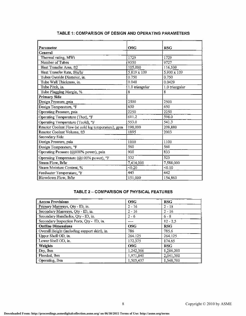
The RSG design pressure and temperature are the sarne as the OSG design pressure and temperature but the operating pressures are slightly different. Table 1 provides a comparison of the major design and operating parameters for the RSG and the OSG. All numerical values in the table are per steam generator, where applicable. The thermal ratings of the RSGs and OSGs are the same. The RSGs have larger number of tubes but the tube wall thickness is slightly thinner. Therefore, the heat transfer area is about 10% higher which compensates for the lower heat transfer coefficient of Alloy 690 tubing compared to Alloy 600. The RSG primary side volume is slightly greater than that of the OSG due to a larger internal volume of the tube bundle.
The RSGs are qualified to operate in the Thot range from 598 to 611F. The reactor coolant flow rate and the steam flow rate are slightly higher for the RSGs. The steam generator blow down rate is designed to be at least 2% of the feed water flow rate.
Design Features
Many design improvements were made to address operating experiences of the OSGs and to enhance the RSGs overall reliability and maintainability. These included the use of forgings for the steam generator shell, instead of plates, improved materials for tubing, tube supports and feedwater distribution system, improved design of the tube-to-tubesheetjoints, tube supporting structures, feedwater ring and the channel head, as well as inclusion of an integral steam flow limiter. The RSGs have improved access provisions for maintenance and inspections, and improved access to the internal components.
The steam generators consist of several major components: the upper and lower shell with transition cone and elliptical upper head, tube bundle, tube supports, tubesheet and channel head, feedwater distribution system, moisture separation equipment and access provisions. The elevations of the RSG level taps are such that the level setpoints for the RSGs are the same as for the OSGs. The elevations and orientations of the other RSG instrument taps are similar to those for the OSGs, and are such that the existing sensing lines can be easily reconnected. The
locations of the large hot leg, cold leg, mainstearn and feedwater nozzles in RSG are identical to those of the OSG, in order to eliminate the need for modification of the major piping. The RSGs are supported in the same manner as the OSGs, utilizing the existing sliding base, key brackets and snubber assemblies. The overall dimensions and weights of the RSG and OSG are almost the same as shown in Table 2.
Tubiug
The main reason to replace the existing steam generators is the OSG tubes are made of Alloy 600 material which is susceptible to intergranular attack (IGA) and stress corrosion cracking. The RSG tube material is thermally treated Alloy 690 (Alloy 690 TT). Alloy 690 TT has been under development since the early 1970s, and based on extensive industry-wide tests, bas been determined to be the material of choice for use in the replacement steam generators industry-wide. Both laboratory testing and operational experience have proven that Alloy 690 TT is much more resistant to IGA and stress corrosion cracking in both primary and secondary water environments than Alloy 600.
The number of heat transfer tubes in RSG is 9727 and is 9350 in OSG. The RSG tube bundle is approximately 17 inches taller than the OSG tube bundle. The outside diameter of the RSG and OSG tubing are both 0.75". However, the RSG tubing wall thickness is 0.0429 inch which is smaller than the OSG tubing wall thickness of 0.048 inch. This is because the RSG tubing uses a higher strength material of Alloy 690 TT as compared to OSG material of Alloy 600. With larger number of tubing and taller tube bundles, the RSG nominal heat transfer surface area is 116,100 sq. ft. which larger than the OSG surface area ofapproximateiy 105,000 sq. ft.
Tube Supports
The RSG tubes are supported by tube support plates in the straight-leg region and by an antivibration bar (A VB) structure in the U-bend region. In the RSG, the tubes are supported in place by seven tube support plates with broached and trefoil tube holes. The tube support plates are designed to reduce the tube-to-tube support plate crevice area while providing for a maximum steam/water flow in the open areas adjacent to
Downloaded From: http://proceedings.asmedigitalcollection.asme.org/ on 06/30/2015 Terms of Use: http://asme.org/terms
3 Copyright © 2010 by ASME
the tube. Flat-land tube-to-tube support plate contact geometry provides additional margin for dryout. The tube support plates are made of Type 405 ferritic stainless steel. Materials are selected to minimize the potential for tube wear and denting due to tube suppOli plate corrosion. In the OSG, the tubes are supported by egg-crate grid type tube supports, constructed from straight bars that are sized to fill the interstitial space between the tubes. The egg-crate bars are made of carbon steel. In the RSG, six sets of V-shaped AVBs, providing up to 12 support points per tube, are installed in the U-bend region to provide support in the region where the tubes are most susceptible to degradation due to wear from flow-induced vibration. During RSG fabrication, the thickness of the A VBs and the tube-to-A VB gap were tightly controlled. The 12 tube support points provide redundancy, so that all the tubes remain fluid-elastically stable even if some of the support points are inactive. The A VBs are nearly perpendicular to the centerline of the tubes at all 12 support locations to provide support while minimizing the tube-to-A VB contact length (to minimize the potential for local corrosion and wear). These features of the U-bend support system provide significant margin against flow stagnation, corrosion, and tube vibration. In the OSG, tube U-bend configuration includes two 90-degree bends on either side of a horizontal run, and the support system includes relatively wide diagonal batwings and vertical strips for supporting the horizontal run of the bends, all made of carbon steel.
Tubesheet and Channel Head
In the OSG, the channel head design includes a tubesheet with center supported by a stay cylinder, which permits the tubesheet thickness to be minimized. In the RSG, he tubesheet is thicker and is supported only by a structural divider plate. This design approach allows for more heat transfer tubes and eliminates the "cold zone" in the center region of the tube bundle, which is considered a likely conrributor to tube wear in the bundle U-bend central region. The RSG tubesheet is a single piece forging with integral weld preparations. The RSG reactor coolant volume is approximately 5% more than the OSG volume, but still within the allowable limit dictated by the containment building flooding analysis.
In the RSG, the channel head has a fiat bottom and the outlet plenum is self-draining. The inlet and outlet nozzles contain integral grooves for installation of the nozzle dams with quick locking pins and inflatable seals for primary side inspection and maintenance operations. The design also includes provisions for preventing reactor coolant spillage during manway cover removal. The RSG reactor coolant inlet nozzle design incorporates a flow limiting orifice in order to offset the effect of increased number of tubes (in terms of the primary side flow resistance) on the reactor coolant flow rate, and maintain this rate within the allowable limits. The OSG design does not include the provisions mentioned above.
Upper and Lower Shell
In the RSG, forgings are used for fabrication of all pressure boundary parts: channel head, lower and upper shell, transition cone, and major nozzles. This method is used to minimize the number of pressure boundary welds. The OSG shell is fabricated from plates and includes both circumferential and longitudinal welds. The RSG upper shell diameter is the same as the OSG diameter; the RSG lower shell diameter is approximately 2 inches larger !ban the OSG diameter. The RSG main steam outlet nozzle has a flow-limiting device, consisting of seven venturi nozzles with a throat ill of 8.56 inches. This devise is used to reduce the rate of mass/energy release into the containment during a postulated Main Steam Line Break (MSLB) inside containment. It also reduces the loads on the steam generator internals during such an event. The OSG design does not include an integral steam fiow limiting device.
The RSG blowdown provisions are in a form of a peripheral open channel on the secondary side of the tubesheet, with the 4-inch blowdown nozzle attached to the tubesheet. The channel provides for complete drainage of the secondary side, so the blowdown nozzle serves also as a secondary side drain nozzle. The OSG design includes 2-inch carbon steel internal blowdown piping with a 2-inch blowdown nozzle attached above the tubesheet.
Downloaded From: http://proceedings.asmedigitalcollection.asme.org/ on 06/30/2015 Terms of Use: http://asme.org/terms

4 Copyright © 2010 by ASME
Feedwater Distributiou System
Feedwater is iutroduced into the RSG through a feedwater nozzle located on the upper shell. The nozzle contains a welded Alloy 690 thermal sleeve, which minimizes the impact of large temperature transients on the nozzle and shell during cold auxiliary feedwater injection. The feedwater ring design includes an internal "goose neck" extending above the elevation of the feedwater spray nozzles. This feature eliminates thermal stratification in the feedwater nozzle and the connecting feedwater piping, and prevents the feedwater ring from draining on loss of main feedwater flow, thus minimizing the potential for water hammer. The OSG design employs a thermal sleeve and a distribution box, and does not include features preventing thermal stratification or water hammer on loss of feedwater flow.
The RSG feedwater ring is designed to uniformly distribute the feedwater flow around the upper shell. Special perforated nozzles are spaced around the top of the feedwater ring to distribute the feedwater into the upper shell recirculation water pool without impinging on any internals. The purpose of the perforated nozzle design is to capture loose parts that may enter the RSG with feedwater and provide for feedwater flow pressure reduction. The nozzle location prevents the feedwater ring from draining, thus eliminating the potential for water hammer on steam generator water level decrease. The OSG feedwater ring utilizes "J-nozzles" to reduce the potential for water hammer on steam generator water level decrease.
The RSG feedwater ring is fabricated from CrMo alloy steel with Alloy 690 IT fittings, which provide increased resistance to erosion/corrosion. The OSG feedwater ring is fabricated from carbon steel, which has a much lower resistance to erosion/corrosion.
Moisture Separation Equipment
The moisture separation equipment includes the moisture separators and steam dryers. The RSG design includes 38, 20-inch, high performance centrifugal moisture separators welded to the lower deck plate. The moisture separators use swirl vane, riser separating, and outlet orifice design features, and are made of Cr-Mo lowalloy steel resistant to erosion/corrosion. The OSG design includes 212 moisture separators of
a smaller diameter made of carbon steel, which are bolted to the lower deck plate.
The RSG design includes eight banks of singletier dryers with perforated panels on the inlet side and layers of tightly packed dryer vanes inside each bank. The RSG single-tier dryer bank spacing and the total length of the banks provides much more separating capacity than is available in the OSG dryer arrangement. RSG steam dryer performance is further enhanced through the use of peerless double-pocket highcapacity dryer vanes. Drain pipes carry the captured water from the dryers downward into the recirculation pool. The OSG design includes a set of 162 steam dryers that have much smaller moisture separation capacity.
Access Provisions
The RSG and OSG access provisions are compared in Table 2. The RSG has two 18-inch primary manways on the channel head, and two 16-inch secondary manways on the upper shell. The OSG has two smaller 16-inch primary manways on the channel head and two 16-inch secondary manways on the upper shell. The RSG has four 8-inch handholes located on the extension ring just above the tubesheet and two 8-inch handholes located on the transition cone just above the uppermost tube support plate. The OSG only has two 6-inch handholes on the secondary side above the tubesheet. In addition, the RSG has twelve 2.S-inch inspection ports. Two inspection ports, l80-degrees apart, are located above each of the six lower tube support plates. Each handhole and inspection port provides access to the tube bundle via a sleeve and a closable penetration in the wrapper. The OSG does not have shell penetration provisions for upper bundle or individual tube support inspection access.
The RSG elliptical upper head design offers more upper shell space for access as compared to the OSG hemispherical head design. Access to the RSG bottom and top of the steam dryers and the steam nozzle is provided via hinged hatches. The OSG design does not provide such access. The RSG downcomer annulus at the feedwater nozzle orientation is much wider at the top than in the OSG, thereby facilitating access to the nozzle and feedwater ring. The access above the feedwater ring is provided via an annular space between the lower moisture separator deck plate and upper shell. The feedwater ring is equipped
Downloaded From: http://proceedings.asmedigitalcollection.asme.org/ on 06/30/2015 Terms of Use: http://asme.org/terms
5 Copyright © 2010 by ASME
with two closable access ports, 180 degrees apart, for remote inspection and foreign material retrieval. The OSG annulus above the feedwater ring is of a smaller size, thereby restricting accessibility for maintenance or inspection. The feedwater ring itself does not have any access provisions. The access to the tube bundle V-bend
OTHER RELATED CHANGES
There are many changes required to support the steam generator replacement. The major change packages prepared are (i) Contairnnent Opening, (ii) Reactor Coolant System (RCS) Tie-in, (iii) Rigging and Handling of Stearn Generators (iv) Mainsteam, Feedwater, and Blowdown Lines, (v) New Thermal Insulation
Containment Opening
The existing equipment hatch at SONGS is too small and is not in a location that would permit the movement of the steam generators. Therefore, a temporary containment opening construction was required. After the installation of the steam generators, the contairunent opening was closed and restored to the original design condition. The contairnnent building is a safety related post-tensioned reinforced concrete stmcture with 52" thick walls containing conventional horizontal and vertical reinforcing steel near the inside and outside face, horizontal and vertical tendons encased in tendon sheaths embedded in the center portion of the wall, radial reinforcing ties, and a \4" thick steel liner plate on the inside face of the wall. The creation and closure of the construction opening involved the removal and reinstallation of each of the above components as well as electrical commodities installed on the liner plate ..
RCS Tie-in
In order to remove the OSG and install the RSG, the RCS piping were cut at the hot leg and at both cold legs, in conjunction with installation of any required temporary supports. After cutting of the RCS piping, the severed end of the remaining RCS hot leg and cold legs were decontaminated. Temporary covers were provided and installed over the open ends of the remaining RCS pipe to protect the openings from damage, to prevent the intrusion of foreign materials into the ReS, and to reduce local dose rates. Once proper fit-up
region in the RSG is provided via hinged hatches while the OSG is provided via a manway with bolted cover. The RSG also has a unique design of moisture separators that permit direct access of video equipment to the tube bundle V-bend for remote inspections.
between the RSG nozzles and the RCS hot leg and cold legs was achieved, proper fit-up of permanent RSG supports, and any required steam generator temporary restraints were installed to maintain fit-up. Then the weld between the steam generator nozzles and the RCS piping (hot leg and cold legs) was performed. Automated welding process was used and qualified by NDE process. Temporary RCS supports were removed after the RCS was secured in place.
Rigging and Handling of Steam Generators
The rigging and handling of the OSGs and RSGs outside the containment building were accomplished by the use of Outside Lifting System (OLS). The support towers of the runway and OLS are constmcted of reusable, multifunction, Vertical Pole System (VPS) cOIIlpoIll;ml~. The VPS structural connections consist primarily of high-strength bolts and pins to facilitate assembly and disassembly. The runway and OLS girders consist of side-by-side built-up plate girders which span the support towers. As with the majority of the components, these girders have also been designed for reuse and have been used previously in heavy rigging operations.
The rigging of the RSGs was in reverse order of the OSGs. RSGs are provided with welded in place lifting trunnions located on the upper shell. The RSGs were moved from the on-site storage area to the Containment Building with the trunnions in the horizontal position, lifted by the OLS using belly slings, and moved into the Containment.
The rigging and handling of the OSGs and RSGs inside the containment building were accomplished by the use of Polar Crane, Temporary Handling Device (THD) and Temporary Support Stmcture (TSS). THD is a hydraulically operated gantry type trolley that is designed to travel on the existing polar crane bridge girder rails. It is designed to lift the full weight of a steam generator and attached rigging
Downloaded From: http://proceedings.asmedigitalcollection.asme.org/ on 06/30/2015 Terms of Use: http://asme.org/terms
6 Copyright © 2010 by ASME
appurtenances. The THD has a larger lift capacity and higher lift range than the existing polar crane hoist trolley, and was used to lift the OSGs out of their compartments and down-end them onto transfer carts on the inside runway system. The RSGs likewise were upended from the transfer carts and rigged to their final position within the cubicles using the THD. The THD and its associated rigging components (such as link plates, key-hole plates, and swivel/spreader beams) were attached to the OSG lifting plug and the RSG trunnions. The TSS is a frame used to temporarily support the SGs during rigging The SGs were temporarily set and secured in the TSS during the SG rigging process to allow rotation of the polar crane without the load from the SGs.
Mainsteam (MS), Feedwater (FW), and Blowdown (BD) Lines
In order to remove OSGs and install RSGs, the MS, FW, and ED lines were cut in conjunction with the installation of any required temporary supports. The MS pipe cut is located near the OSG nozzle. The other MS pipe cut is located further downstream from the SG nozzle along the horizontal pipe run to minimize the potential for foreign material entry into the piping. The cut pipe spool was temporarily removed and stored for reuse. Portions of the FW piping and the associated supports and pipe whip restraints were removed to facilitate the removal of the OSGs and the installation of the RSGs. The cuts are located at the SG FW nozzle and at 20 inches check valve downstream outside the SG cubicle. Temporary covers were installed over the open ends of the removed spool pieces of piping to avoid foreign material intrusion. The BD line was removed and modified due to the new RSG BD nozzle location 3 feet lower than the existing BD nozzle and the nozzle size is also slightly different. Design improvements such as material upgrade and modifications to facilitate service inspections are made for the MS, FW, and BD lines.
New Thermal Insulation
The insulation of the OSGs and portion of the piping connected to the OSGs was removed. New thermal insulation was installed on the RSGs and portions of connected piping of the reactor coolant system, mainsteam, feedwater, and blowdown piping. The original thermal insulation system consists of encapsulated
mineral wool and reflective metal insulation (RMI). The replacement thennal insulation is entirely RMI. The replacement RMI panels are supported by steel rings that are friction clamped to the SG shell. Each support ring consists of segments of steel angle joined with fasteners. Clamping force is provided by torquing of the fastener bolting. A support ring is typically installed between each level of panels. The individual panels are buckled to each other. No screws are utilized in the installation of the panels. The panel design and layout facilitate the access to handholes, manways, and other areas for maintenance and inspection.
DIFFICULTIES DURING INSTALLATION
There were many difficulties encountered during the installation of the RSGs. A few significant cases are mentioried below.
Tendon
In order to create an opening on the containment wall, 82 tendons had to be removed. The tendon anchor wedge type design does not permit partial detensioning. It can ouly be removed by burning off the strands fIxed at the anchor. Since there is grease along the strands or tendon, they can catch ftre easily. Fire watch and fire control were carried out to avoid the tendon or strands catching fire during the tendon removal process. Proper procedure had to be followed. Nevertheless, there were s_everal minor fire events during the detensioning process.
Piping Tie-in
Cold pulling was used to fit up and weld the removed portion of the main steam piping to the RSG. The pulling of the main steam pipe spool caused some modifications of a number of supports. The ReS piping has a short section of piping between the steam generator nozzle and RCS elbow. The piping is of wall thickness about half an inch less than the steam generator nozzle and the RCS elbow. Welding back the existing elbow with the piping extension piece to the steam generator created a great challenge to enable pre-service and future in-service inspections of these welds. The change in smface level caused extreme ultrasonic examination restrictions. Extended work to weld the RCS in place caused more radiation exposure for the steam generator replacement operation.
Downloaded From: http://proceedings.asmedigitalcollection.asme.org/ on 06/30/2015 Terms of Use: http://asme.org/terms
7 Copyright © 2010 by ASME
Blowdown Whip Restraints
Since the blowdowo nozzle of the RSG is 3 feet lower than hefore, the blowdown line had to be rerouted and the supports redesigned. The blowdown whip restraiots were found to bave field ioterference during iostallation. Field walkdowns dnriog outage and redesign work were needed to accomplish the iostallation of the blowdown whip restraints.
Rigging and Handling
Dnriog the transportation of the second RSG, just outside the contairunent opening, one nOll
load beariog component of the transporter broke. The event happened at around I AM io the morning. Responsible personnel were called io from home and worked with the vendor to get the problem fixed since the operation was in critical path. The component was redesigned and reinstalled to move the RSG inside the containment successfully within a short period of time.
LESSONS LEARNED
In order to avoid fire during the removal of tendons, grease will be rninimiL;tKl and additional compensatory measures will be implemented. Spare sections of replacement piping will be pnrchased to avoid cold pulliog. The existiog pipiog between the SG nozzle and RCS elbow will be replaced with piping of matching thickness. Careful consideration of the field problems will be made for the design of new or modified supports. It is recommended video are taken during walkdowo to have a better view of the surrouodiog areas for the identified problems or systems. The components of the transporter for the RSGs will be modified to withstand larger loads. These are a few of the main lessons leaned. More than a huodred lessons learned were compiled.
CONCLUSION
To extend the service life of a PWR, steam generator replacement is inevitable and the expenditnres will be recouped by contioued generation efficiently. SGs are and will be replaced io many more PWRs with SG tubes made of Alloy 600 io the world. This paper provides some iosight for the latest RSG design by one of the SG manufaclurers and associated
chaages due to SG replacement at SONGS. Due to complexity of the iostallation, certaio problems were encountered during the installation ofRSGs for the first replacement Unit io SONGS. SONGS management and engioeeriog had compiled lessons learned io the Unit 2 project which will be implemented io for Unit 3 SG replacement during the fall of20l0.
REFERENCES
[1] Southern California Edison Conformed Specification for Design and Fabrication of the Replacement Steam Generators for Unit 2 and Unit 3.
[2] Southern California Edison Replacement Steam Generators Installation, San Onofre Generation Station Unit 2 and Unit 3.
[3] San Onofre Nuclear Generating Station NSSS Units 2 and 3 Licensing Topical Report.
ACKNWOLEGEMENT
The authors would like to acknowledge the support aad technical input they received from Mr. Craig Harberts and Mr. Bob Olech of Southern California Edison, and Mr. Hiroshi Hiraao of Mitsubishi Heavy Industries, Ltd.
Downloaded From: http://proceedings.asmedigitalcollection.asme.org/ on 06/30/2015 Terms of Use: http://asme.org/terms
8 Copyright © 2010 by ASME
TABLE 1: COMPARISON OF DESIGN AND OPERATING PARAMETERS
Parameter OSG RSG General Thermal rating, MWt 1729 1729 Number of Tubes 9350 9727 Heat Transfer Area, ft2 105,000 116,100 Heat Transfer Rate, Btu/hr 5.819 x 10⁹ 5.900x 10⁹ Tubes Outside Diameter, in. 0.750 0.750 Tube Wall Thickness, in. 0.048 0.0429 Tube Pitch, in. 1. 0 triangular 1.0 triangular Tube Plugging Margin, % 8 8
Primary Side Design Pressure, psia 2500 2500 Design Temperature, of 650 650 Operating Pressure, psia 2250 2250 Operating Temperature (That), OF 611.2 598.0 Operating Temperature (Tcold), of 553.0 541.3 Reactor Coolant Flow (at cold leg temperature), gpm 198,000 209,880 Reactor Coolant Volume, ft3 1895 2003 Secondary Side Design Pressure, psia 1100 1100 Design Temperature, of 560 560 Operating Pressure (@100%power),psia 900 833
Operating Temperature (@IOO%power), of 532 523 Steam Flow, Ib/hr 7,414,000 7,588,000 Steam Moisture Content, % <0.20 <0.10 Feedwater Temperature, of 445 442 Blowdown Flow, Ib/hr 151,000 154,860
TABLE 2 - COMPARISON OF PHYSICAL FEATURES
Access Provisions OSG RSG Primary Manways, Qty - ill, in. 2 - 16 2 - 18 Secondary Manways, Qty - ill, in. 2 - 16 2 - 16 Secondary Handholes, Qty -ill, in. 2-6 6-8 Secondary Inspection Ports, Qty - ill, in. ---- 12 - 2.5 Outline Dimensions OSG RSG Overall Height (including support skirt), in. 786 785.6 Upper Shell OD, in. 264.125 264.125 Lower Shell OD, in. 172.375 174.65 Weights OSG RSG Dry, Ibm 1,242,366 1,286,200 Flooded, Ibm 1,971,840 2,041,300 Operating, Ibm 1,505,437 1,548,700
Downloaded From: http://proceedings.asmedigitalcollection.asme.org/ on 06/30/2015 Terms of Use: http://asme.org/terms

9 Copyright © 2010 by ASME
Integra! Flow Hemispherical Restrictor Head
Elliptical Head
Elevated
Square Feedwater Ring
U-bend Batwing Supports .l:i
O{ AVBs .~
OJ
::r:: Broached TSPs ~
~ Eggcrntc
;.-I 0 AIloy690TI
Supports
I OJ
tubes S '" Alloy 600 MA I <Zl
tubes
Stay Cylinder No Stay Cylinder
Original SG Replacement SG
FIGURE 1 - COMPARISON OF ORIGINAL SG AND REPLACEMENT SG DESIGN
Downloaded From: http://proceedings.asmedigitalcollection.asme.org/ on 06/30/2015 Terms of Use: http://asme.org/terms