steam reforming on transition-metal carbides from …
TRANSCRIPT

Steam reforming on transition-metal carbides from
density-functional theory
Aleksandra Vojvodic1, 2, ∗
1Department of Applied Physics, Chalmers University
of Technology, SE-412 96 Goteborg, Sweden
2SUNCAT Center for Interface Science and Catalysis,
SLAC National Accelerator Laboratory,
2575 Sand Hill Road, Menlo Park, CA 94025, USA
Abstract
A screening study of the steam reforming reaction on clean and oxygen covered early transition-
metal carbides surfaces is performed by means of density-functional theory calculations. It is
found that carbides provide a wide spectrum of reactivities, from too reactive via suitable to too
inert. Several molybdenum-based systems are identified as possible steam reforming catalysts. The
findings suggest that carbides provide a playground for reactivity tuning, comparable to the one
for pure metals.
Keywords: DFT, steam-reforming,carbides,surfaces,reactivity trends
1
SLAC-PUB-15019
Work supported by DOC Contract DE-AC02-76SF00515 and the Swedish Research Council.

I. INTRODUCTION
Steam reforming is an important industrial process, where natural gas (CH4) is converted
into synthesis gas (CO and H2) according to the overall reaction
CH4 + H2O CO + 3H2. (1)
The synthesis gas is subsequently transformed into more valuable chemicals, such as am-
monia, methanol, and diesel. Since steam reforming acts as a source of hydrogen, it is also
potentially important for any emerging hydrogen economy. For a detailed review of the
steam reforming process and its applications see for example Ref. 1.
Commercially the steam reforming reaction is conducted over a Ni-based catalyst due to
the relatively low cost and good activity of nickel. This reaction has been studied in detail
on the close-packed Ni(111) surface and on the stepped Ni(211) surface by means of density-
functional theory.2 The major technological challenge for Ni catalysts is the formation of
carbonaceous deposits, termed coke, that lead to catalyst deactivation. In Refs. 2,3 it
was established that the step edges on Ni surfaces act as growth centers for graphite. Other
transition metals (TM), such as Ru, Rh, Pd, Ir, and Pt also show high activity and selectivity
towards steam reforming4 and have a high resistance against carbon formation. However,
these materials are scarce in nature and expensive. Therefore new materials that are resistant
to carbon formation are needed.
Transition-metal carbides (TMC’s) have gained quite some attention since Levy and
Boudart reported that they have ”platinum-like behavior” for certain reactions.5 The start-
ing material for the production of carbides is cheap and abundant and therefore it has been
suggested that they can replace the noble metals in catalysis. The main problem with the
carbides has been to produce materials with sufficiently high surface area for them to be
interesting for catalytic applications. This problem has been overcome and several studies
report on carbides with surface areas as high as 200 m2/g.6–9
In Refs. 10 and 11, it was shown that carbides of molybdenum and tungsten are stable
and active catalysts for not only the steam reforming but also the dry reforming and the
partial oxidation of methane at elevated pressures. Moreover, no macroscopic carbon was
deposition on the catalysts during the catalytic reactions. The relative activity of a number
of steam reforming catalysts was established as: Ru > Rh > Ir ≈ Mo2C > WC> Pd > Pt.
2

d)a) b) c) e)
FIG. 1: Top view of the relaxed (a) Mo-terminated δ-MoC(111), (b) C-terminated δ-MoC(111),
(c) δ-MoC(100), (d) Mo-terminated α-Mo2C(100), (e) C-terminated α-Mo2C(100) surface. The
blue and black balls represent the Mo and C atoms, respectively. The black dashed lines indicate
the unit cell.
Several density-functional theory studies concerning adsorption on TMC’s have been
conducted, for example, atomic adsorption,12–20 O2 adsorption,21 CO adsorption,22–24 NHx
(x = 1− 3) adsorption,19,20 methanol adsorption,25 CHx (x = 0− 3) and C2H4 adsorption.26
In addition, the water-gas-shift reaction has been studied in Refs. 27–29.
To our knowledge, a theoretical understanding of the steam reforming reaction on TMC’s
is missing in the literature. The aim of this paper is to investigate how the TMC’s are suited
for the steam reforming reaction by performing a set of density-functional theory (DFT)
calculations on different surfaces of α-Mo2C, TiC, VC, and δ-MoC in order to catch the
trends between TMC’s composed of different TM atoms and of different structures. The
influence of the surfaces being covered with oxygen is also investigated.
The outline of this paper is as follows. To begin with the systems to be investigated
are defined in Sec. II. This is followed by Sec. III, which describes the calculation details.
Our results are presented in Sec. IV and discussed in Section V. The paper ends with a
conclusion in Section VI.
II. INVESTIGATED TMC SYSTEMS
The Mo–C system can occur in several crystalline forms, see for example the phase
diagrams in Refs. 30 and 31. There are two types of Mo2C phases, one orthorhombic
(α) and one hexagonal (β), which is a high temperature phase. In this study, we focus
on the α phase. For this phase the Mo atoms are only slightly distorted from an hcp
arrangement and the carbon atoms occupy one half of the octahedral interstitial sites. In
3
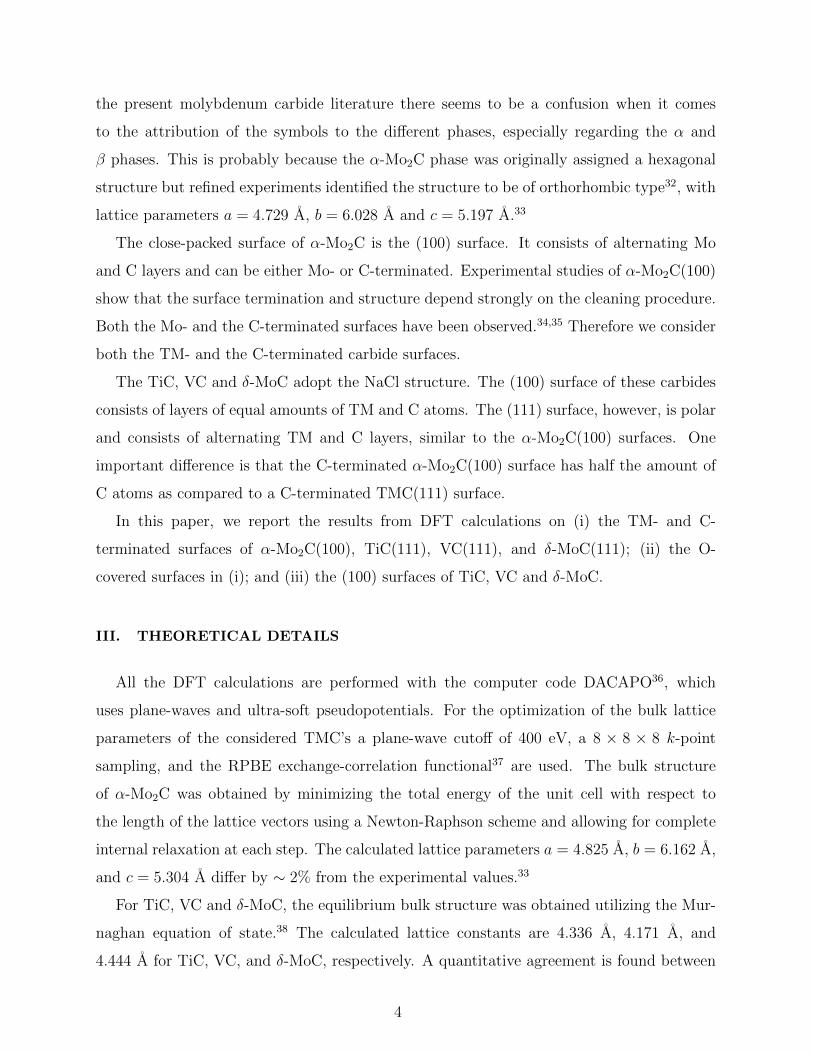
the present molybdenum carbide literature there seems to be a confusion when it comes
to the attribution of the symbols to the different phases, especially regarding the α and
β phases. This is probably because the α-Mo2C phase was originally assigned a hexagonal
structure but refined experiments identified the structure to be of orthorhombic type32, with
lattice parameters a = 4.729 A, b = 6.028 A and c = 5.197 A.33
The close-packed surface of α-Mo2C is the (100) surface. It consists of alternating Mo
and C layers and can be either Mo- or C-terminated. Experimental studies of α-Mo2C(100)
show that the surface termination and structure depend strongly on the cleaning procedure.
Both the Mo- and the C-terminated surfaces have been observed.34,35 Therefore we consider
both the TM- and the C-terminated carbide surfaces.
The TiC, VC and δ-MoC adopt the NaCl structure. The (100) surface of these carbides
consists of layers of equal amounts of TM and C atoms. The (111) surface, however, is polar
and consists of alternating TM and C layers, similar to the α-Mo2C(100) surfaces. One
important difference is that the C-terminated α-Mo2C(100) surface has half the amount of
C atoms as compared to a C-terminated TMC(111) surface.
In this paper, we report the results from DFT calculations on (i) the TM- and C-
terminated surfaces of α-Mo2C(100), TiC(111), VC(111), and δ-MoC(111); (ii) the O-
covered surfaces in (i); and (iii) the (100) surfaces of TiC, VC and δ-MoC.
III. THEORETICAL DETAILS
All the DFT calculations are performed with the computer code DACAPO36, which
uses plane-waves and ultra-soft pseudopotentials. For the optimization of the bulk lattice
parameters of the considered TMC’s a plane-wave cutoff of 400 eV, a 8 × 8 × 8 k-point
sampling, and the RPBE exchange-correlation functional37 are used. The bulk structure
of α-Mo2C was obtained by minimizing the total energy of the unit cell with respect to
the length of the lattice vectors using a Newton-Raphson scheme and allowing for complete
internal relaxation at each step. The calculated lattice parameters a = 4.825 A, b = 6.162 A,
and c = 5.304 A differ by ∼ 2% from the experimental values.33
For TiC, VC and δ-MoC, the equilibrium bulk structure was obtained utilizing the Mur-
naghan equation of state.38 The calculated lattice constants are 4.336 A, 4.171 A, and
4.444 A for TiC, VC, and δ-MoC, respectively. A quantitative agreement is found between
4

the theoretical and experimental lattice constants.39,40
The surfaces are modeled using the supercell approach, with the DFT lattice parameters
given above. A 400 eV energy cutoff for the plane-wave expansion of the one-electron
orbitals, a 4 × 4 × 1 k-point grid, and the RPBE functional are used. Each TMC(111)
and TMC(100) surface is represented by a slab with the geometry defined in Fig. 1 and a
thickness of four atomic layers. Repeated slabs are separated by at least a 10.8 A thick
vacuum region. The Mo- and C-terminated α-Mo2C(100) slabs have a surface geometry
as defined in Fig. 1 and consist of four layers Mo and four layers C separated by 10.6 A
vacuum. During structural relaxations, the two bottom atomic layers are constrained to the
corresponding bulk geometry.
Figure 1 shows the relaxed structures of the Mo- and C-terminated δ-MoC(111) surfaces,
the δ-MoC(100) surface, and the Mo- and C-terminated α-Mo2C(100) surfaces. These re-
laxed surfaces and the corresponding VC and TiC surfaces are used as starting points for
the modeling of the steam reforming reaction.
The investigated steam reforming reaction is assumed to have the following nine elemen-
tary steps:
CH4 + 2∗ CH∗3 + H∗ (2)
CH∗3+
∗ CH∗2 + H∗ (3)
CH∗2+
∗ CH∗ + H∗ (4)
CH∗+∗ C∗ + H∗ (5)
H2O + 2∗ OH∗ + H∗ (6)
OH∗+∗ O∗ + H∗ (7)
C∗ + O∗ CO∗ (8)
CO∗ CO+∗ (9)
2H∗ H2 + 2∗, (10)
where ∗ (2∗) denotes one (two) empty surface site and X∗ denotes the adsorbate X bonded
to this site. This paper is based on an adsorption energy analysis. Such a thermodynamic
analysis has previously been proven to be able to predict reactivity trends for metals4.
There are two main reasons for this. First, the adsorption energy difference from one metal
to the next are large. Second, there is a correlation between adsorption energies and energy
5

barriers, the so called Brønsted-Evans-Polanyi relations, previously found on metals49 and
a group of carbides20. Hence, the reactivity of a material can to a first order be obtained
directly from a thermodynamic analysis.
In this study we consider adsorption of all the intermediates (CH3, CH2, CH, C, OH, O,
CO, and H) in Eqs. (2)–(10). In all adsorption calculations, the adsorbate coverage is one-
quarter of a monolayer (ML) relative to the number of TM atoms in the surface (subsurface
layer if the surface is C terminated). Adsorption is allowed on one of the two slab surfaces
at the time. Adsorbates together with the surfaces are allowed to relax in all directions until
the forces are less than 0.05 eV/A. The energies in the calculated potential energy diagrams
are expressed relative to the clean surface (O-covered surfaces if the surface is oxygenated),
a CH4 molecule, and a H2O molecule in the gas phase.
The steam reforming reaction on the oxygenated TMC surfaces is modeled by adsorbing
the reaction intermediates on a 1ML O-covered TMC surface. According to DFT calculations
in Ref. 28, the O covering of the Mo- and C-terminated Mo2C(100) surfaces is energetically
favorable up to 1ML. Our calculations give the same structure for the 1ML O-covered Mo-
and C-terminated Mo2C(100) surfaces as in Ref. 28.
IV. RESULTS
This Section focuses on the results obtained from the screening calculations study. We
provide the calculated potential energy diagrams for the steam reforming reaction on all
the considered TMC surfaces. These are compared with existing results on Ni(111) and
Ni(211)2.
A. TMC(111) and α-Mo2C(100) surfaces
The calculated potential energy diagram for the steam reforming reaction on the TM- and
C-terminated TMC’s is shown in Fig. 2. First of all we notice that the span of the potential
energies of the investigated surfaces is huge. Compared to the Ni surfaces2, all these TMC
surfaces are much more reactive because they bind the intermediates too strongly. Therefore
none of these surfaces is suitable for the steam reforming reaction.
In the following we present the trends in reactivity that are found when changing the
6

FIG. 2: Calculated potential energy diagram for the steam reforming reaction on the TM-
terminated (circles) and C-terminated (squares) TMC(111) and α-Mo2C(100) surfaces. For com-
parison the Ni(111) and Ni(211) data, adapted from Ref. 2, are given.
7

TM atom in the TMC compound. For each of the considered TMC’s, the C-terminated
surface is found to be more reactive than the TM-terminated one. This is to be expected for
the monocarbides since the TMC(111) surfaces are found to be TM terminated under UHV
conditions.41,42 All the TM-terminated TMC(111) surfaces have similar potential energy
shape as a function of the reaction intermediates. The same is found for the C-terminated
group of TMC surfaces. For the TM-terminated TMC surfaces, the reactivity can be or-
dered as TiC(111) > VC(111) > α-Mo2C(100) > δ-MoC(111), while for the C-terminated
TMC surfaces we find that the reactivity order is TiC(111) > VC(111) > δ-MoC(111) >
α-Mo2C(100). Hence different trends are observed for the different terminations.
The considered α-Mo2C(100) surfaces are less reactive than the C-terminated δ-MoC(111)
surface but more reactive than the Mo-terminated δ-MoC(111). For a given carbide, the
smallest difference in reactivity between the TM- and the C-terminated surfaces is found for
α-Mo2C(100). This can be due to the fact that the C-terminated α-Mo2C(100) surface has
50% less C than the C-terminated TMC(111) surfaces.
The largest energy change in the potential energy surface is found upon adsorption of
O-carrying intermediates, that is, a strong O–surface bond is formed. This implies that the
TMC(111) surfaces are easily oxidized. Experimental studies show that the O2 adsorption
on TiC(111)43 and α-Mo2C(100)35 are dissociative. Therefore we investigate how the steam
reforming reaction is influenced when the TMC(111) and the α-Mo2C(100) surfaces are
oxygenated.
B. O-covered TMC(111) and O-covered α-Mo2C(100) surfaces
Figure 3 shows the calculated potential energy diagram for the steam reforming reaction
on the 1ML O-covered TM- and C-terminated TMC surfaces. We find that three of the
molybdenum carbide systems the O-covered Mo-terminated δ-MoC(111), the O-covered C-
terminated α-Mo2C(100) and the O-covered Mo-terminated α-Mo2C(100) surfaces resemble
the potential energy of Ni of which the Ni(211) surface is the most active one2. The other O-
covered surfaces are not suitable as catalysts for the steam reforming either because several of
the reaction steps are significantly uphill energetically, or because the surface gets poisoned
by some of the intermediates.
We find that, each of the O-covered TMC surfaces is less reactive than its corresponding
8

FIG. 3: Calculated potential energy diagram for the 1ML O-covered TM-terminated (circles) and
C-terminated (squares) TMC(111) and α-Mo2C(100) surfaces. Also given are the Ni(111) and
Ni(211) data, adapted from Ref. 2.
9
non-oxidized surface. For a given O-covered TMC surface the TM-terminated surface has
higher reactivity than the C-terminated one, in contrast to the finding on the non-oxidized
surfaces. For the O-covered TM-terminated TMC surfaces, the reactivity can be ordered
as follows α-Mo2C(100) > δ-MoC(111) > VC(111) > TiC(111), while for the O-covered C-
terminated TMC surfaces we find that α-Mo2C(100) > TiC(111) > VC(111) > δ-MoC(111).
The order in reactivity between the different surfaces is thus different for the TM- and for
the C-terminated O-covered surfaces.
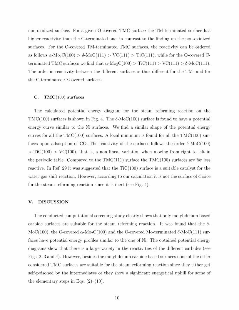
C. TMC(100) surfaces
The calculated potential energy diagram for the steam reforming reaction on the
TMC(100) surfaces is shown in Fig. 4. The δ-MoC(100) surface is found to have a potential
energy curve similar to the Ni surfaces. We find a similar shape of the potential energy
curves for all the TMC(100) surfaces. A local minimum is found for all the TMC(100) sur-
faces upon adsorption of CO. The reactivity of the surfaces follows the order δ-MoC(100)
> TiC(100) > VC(100), that is, a non linear variation when moving from right to left in
the periodic table. Compared to the TMC(111) surface the TMC(100) surfaces are far less
reactive. In Ref. 29 it was suggested that the TiC(100) surface is a suitable catalyst for the
water-gas-shift reaction. However, according to our calculation it is not the surface of choice
for the steam reforming reaction since it is inert (see Fig. 4).
V. DISCUSSION
The conducted computational screening study clearly shows that only molybdenum based
carbide surfaces are suitable for the steam reforming reaction. It was found that the δ-
MoC(100), the O-covered α-Mo2C(100) and the O-covered Mo-terminated δ-MoC(111) sur-
faces have potential energy profiles similar to the one of Ni. The obtained potential energy
diagrams show that there is a large variety in the reactivities of the different carbides (see
Figs. 2, 3 and 4). However, besides the molybdenum carbide based surfaces none of the other
considered TMC surfaces are suitable for the steam reforming reaction since they either get
self-poisoned by the intermediates or they show a significant energetical uphill for some of
the elementary steps in Eqs. (2)–(10).
10

FIG. 4: Calculated potential energy diagram for TMC(100). The Ni(111) and Ni(211) data given
here are adapted from Ref. 2.
An understanding of the reactivity can be achieved by studying the electronic structure of
the surface. In Refs. 15–20 a thorough analysis of the electronic structure established that the
TM-terminated TMC(111) surfaces possess surface resonances (SR’s). These were identified
to be responsible for strong adsorbate-surface bonds. Therefore the high reactivities of the
TM-terminated TMC(111) surfaces (see Fig. 2) are attributed to the presence of these SR’s.
Preliminary electronic structure calculations show that similar resonances are present also
11

a) b) c) d) e)
FIG. 5: Top view of the relaxed preferential binding geometries for, from above, CH3, CH2, CH,
C, H, O, CO and OH for (a) Mo-terminated δ-MoC(111), (b) C-terminated δ-MoC(111), (c) δ-
MoC(100), (d) Mo-terminated α-Mo2C(100), and (e) C-terminated α-Mo2C(100) surfaces. The
blue, black, red, and white balls represent Mo, C, O, and H atoms, respectively.
12

on the layered polar α-Mo2C(100) surfaces, which would explain their high reactivities.
The NaCl TMC(100) surfaces, on the other hand, do not posses any SR’s17,44 and show
a much lower reactivity (see Fig. 4) compared to the TMC(111) surfaces. Since a suitable
candidate, the δ-MoC(100) surface, is found among these surfaces we have tried to change
the reactivity of the TMC(111) surfaces by weakening their SR’s.
The lower reactivities of the O-covered TMC(111) and α-Mo2C(100) surfaces (see Fig. 3),
compared to the corresponding clean surfaces can be understood as follows. Adsorption
of oxygen on the TMC(111) results in a quenching of the SR’s. Thus, the surfaces are
passivated, that is, their ability to form strong bonds with other adsorbates decreases due
to the strong O–surface bond. This result shows that the reactivity of carbides surfaces can
be tuned.
When it comes to the C-terminated surfaces they also posses SR’s in the vicinity of the
Fermi level. Intuitively, these SR’s should be less pronounced as the C-terminated surfaces
can be viewed as a C-covered TM-terminated surface. Hence, the presence of SR’s alone can
not explain the higher reactivity of the C-terminated surfaces. There is, however, another
effect that is present on the C-terminated surfaces namely the interaction between the surface
carbon and some of the adsorbates. This gives rise to surface reconstruction and formation
of weakly bound intermediates.
An important question for catalytic applications is the stability of the candidate materials.
Steam reforming operates over a large range of working conditions with temperatures 700−
1100 ◦C and pressures 1 − 25 bar. The most recent phase diagram for Mo–C systems is
the one by Velikanova et al.31 It shows that the bulk α-Mo2C phase exists for temperatures
< 1440 ◦C, while the δ-MoC is a high temperature phase which exists above 1956 ◦C. Based
only on bulk data, α-Mo2C is preferred over δ-MoC.
When it comes to the stability of a surface the situation can of course differ from the bulk.
According to York and coworkers10,11, Mo2C was active and selective for the stoichiometric
steam reforming of methane to synthesis gas. The catalyst deactivated at atmospheric pres-
sure, but was very stable when elevated pressures were employed, and no carbon deposition
was observed on the catalysts. In those studies the surface characteristics was, however, not
addressed.
A surface characterization of α-Mo2C(100) has been performed in Ref. 34. The surface
preparation consisted of Ar ion bombardment followed by annealing at successively higher
13

temperatures. The surface was found to change from being Mo terminated to C termi-
nated at annealing temperatures above 1300 K. Despite that these surfaces are stable at
temperatures relevant for the steam reforming, our study shows that they are too reactive.
Adsorption of O2 on both the Mo- and the C-terminated α-Mo2C(100) surfaces were found
to be dissociative and the surfaces were covered with oxygen at 800 K.35 This supports the
stability of the O-covered α-Mo2C(100) surfaces.
In addition, stable crystalline molybdenum carbide films prepared by chemical vapor de-
position (CVD) and physical vapor deposition (PVD) have been found to contain either
Mo2C and/or the δ-MoC1−x phase.45–48 Hence it seems plausible that both the O-covered
α-Mo2C(100) and the δ-MoC(100) surfaces may be stable at relevant steam reforming con-
ditions. However, further studies are needed to address the formation of oxycarbide and
what the stable carbon and oxygen coverages are under different reaction conditions.
VI. CONCLUSION
In this paper, a computational screening study of the steam reforming reaction on
transition-mental carbides has been presented. By using a screening approach we are able
to map out the large reactivity space, which ranges from very reactive to inert, provided by
the carbides. This study clearly shows, solely based on thermochemical data, that a steam
reforming carbide catalyst should be molybdenum based and most probably have oxygen
on the surface in some form. Also, this study illustrates the versatility and tunabilty of the
TMC systems. The results can be understood in terms of the previously proposed model
of chemisorption on TMC surfaces, in which surface resonances play crucial roles. Future
studies should address surface stability in the presence of carbon and oxygen under various
conditions, as well as coverage and coadsorption effects. In addition, more detailed studies of
surface electronic structure and kinetics are needed to establish what surface characteristics
that are required of a carbide to make it a suitable catalyst for steam reforming.
Acknowledgments
The author acknowledges support from the Swedish Research Council and from the U.S.
Dept. of Energy, Office of Basic Energy Sciences. The calculations were performed at
14

HPC2N via the Swedish National Infrastructure for Computing. The author thanks An-
ders Hellman, Carlo Ruberto, Bengt I. Lundqvist and Jens K. Nørskov for constructive
discussions and comments on the manuscripts.
∗ Electronic address: [email protected]
1 J. R. Rostrup-Nielsen, J. Sehested and J. K. Nørskov, Adv. Catal. 47, 65 (2002).
2 H. S. Bengaard, J. K. Nørskov, J. Sehested, B. S. Clausen, L. P. Nielsen, A. M. Molenbroek
and J. R. Rostrup-Nielsen, J. Catal. 209, 365 (2002).
3 S. Helveg, C. Lopez-Cartes, J. Sehested, P. L. Hansen, B. S. Clausen, J. R. Rostrup-Nielsen, F.
Abild-Pedersen, and J. K. Nørskov, Nature 427, 426 (2004).
4 G. Jones, J. G. Jakobsen, S. S. Shimb, J. Kleis, M. P. Andersson, J. Rossmeisl, F. Abild-
Pedersen, T. Bligaard, S. Helveg, B. Hinnemann, J. R. Rostrup-Nielsen, I. Chorkendorff, J.
Sehested, and J. K. Nørskov, J. Catal. 259, 147 (2008).
5 R. B. Levy and M. Boudart, Science 181, 547 (1973).
6 L. Volpe and M. Boudart, J. Solid State Chem. 59, 348 (1985).
7 J. S. Lee, S. T. Oyama, and M. Boudart, J. Catal. 106, 125 (1987).
8 J. S. Lee, K. H. Lee, and J. Y. Lee, J. Phys. Chem. 96 362 (1992).
9 S. T. Oyama, The Chemistry of Transition Metal Carbides and Nitrides, edited by S. T. Oyama
(Blackie Academic and Professional, Glasgow (1996).
10 A. P. E. York, J. B. Claridge, A. J. Brungs, S. C. Tsang, and M. L. H. Green, Chem. Commun.
1, 39 (1997).
11 J. B. Claridge, A. P. E. York, A. J. Brungs, C. Marquez-Alvares, J. Sloan, S. C. Tsang and
M. L. H. Green, J. Catal. 180, 85 (1998).
12 Y. F. Zhang, J. Q. Li, and L. X. Zhou, Surf. Sci. 488, 256 (2001).
13 J. Kitchin, J. K. Nørskow, M. A. Barteau, and J. G. Chen, Catal. Today 105, 66 (2005).
14 F. Vines, C. Sousa, F. Illas, P. Liu, and J. A. Rodriguez, J. Phys. Chem. C 111, 1307 (2007).
15 A. Vojvodic, C. Ruberto and B. I. Lundqvist, Surf. Sci. 600, 3619 (2006).
16 C. Ruberto, A. Vojvodic and B. I. Lundqvist, Surf. Sci. 600, 1612 (2006).
17 C. Ruberto and B. I. Lundqvist, Phys. Rev. B 75, 235438 (2007).
18 C. Ruberto, A. Vojvodic and B. I. Lundqvist, Solid State Commun. 141, 48 (2007).
15

19 A. Vojvodic, C. Ruberto and B. I. Lundqvist, J. Phys.: Condens. Matter 22, 375504 (2010)..
20 A. Vojvodic, A. Hellman, C. Ruberto and B. I. Lundqvist, Phys. Rev. Lett. 103, 146103 (2009).
21 F. Vines, C. Sousa, F. Illas, P. Liu, and J. A. Rodriguez, J. Phys. Chem. C 111, 16982 (2007).
22 S. V. Didziulis, P. Frantz, L. C. Fernandez-Torres, R. L. Guenard, O. El-bjeirami, and S. S.
Perry, J. Phys. Chem. 105, 5196 (2001).
23 P. Liu, and J. A. Rodriguez, J. Chem. Phys. 120, 5414 (2004).
24 J. Ren, C.-F. Huo, J. Wang, and H. Jiao, Surf. Sci. 596, 212 (2005).
25 C. Pistonesi, A. Juan, A. P. Farkas, and F. Solymosi, Surf. Sci. 602, 13 (2008).
26 J. Ren, C.-F. Huo, J. Wang, Z. Cao, Y.-W. Li, and H. Jiao, Surf. Sci. 600, 2329 (2006).
27 H. Tominaga, and M. Hagai, J. Phys. Chem. B 109, 20415 (2005).
28 P. Liu, and J. A. Rodriguez, J. Phys. Chem. B 110, 19418 (2006).
29 F. Vines, J. A. Rodriguez, P. Liu, and F. Illas, J. Catal. 260, 103 (2008).
30 J. Dubois, T. Epicier, C. Esnouf, G. Fantozzi, and P. Convert, Acta Metall. 36, 1891 (1988).
31 T. Y. Velikanova, V. Z. Kublii, and B. V. Khaenko, Soviet Powder Metall. Met. Ceram. 27, 891
(1988).
32 E. Parthe, and V. Sadagopan, Acta Crystallogr. 16, 202 (1963).
33 S. Otani, and Y. Ishizawa, J. Cryst. Growth 154, 202 (1995).
34 T. P. St. Clair, S. T. Oyama, D. F. Cox, S. Otani, Y. Ishizawa, R.-L. Lo, K. Fukui, and Y.
Iwasawa, Surf. Sci. 426, 187 (1999).
35 T. P. St. Clair, S. T. Oyama, D. F. Cox, Surf. Sci. 468, 62 (2000).
36 S. R. Bahn and K. W. Jacobsen, Comput. Sci. Eng. 4, 56 (2002);
http://wiki.fysik.dtu.dk/dacapo.
37 B. Hammer,L. B. Hansen, and J. K. Nørskov, Phys. Rev. B 59, 7413 (1999).
38 C.-L. Fu, and K.-M. Ho, Phys. Rev. B 28 5480 (1983).
39 K. Nakamura, and M. Yashima, Mater. Sci. Eng. B 148 69 (2005).
40 A. Fernandez Guillermet, J. Haglund, G. Grimvall, Phys. Rev. B 45, 11557 (1992).
41 M. Aono, C. Oshima, S. Zaima, S. Otani, and Y. Ishizawa, Jpn. J. Appl. Phys. 20, L829 (1981).
42 J. Rundgren, Y. Gauthier, R. Baudoing-Savois, Y. Joly, and L. I. Johansson, Phys. Rev. B. 45,
4445 (1992).
43 A. M. Brandshaw, J. F. van der Veen, F. J. Himpsel, and D. E. Eastman, Solid State Commun.
37, 37 (1980).
16

44 C. Oshima, M. Aono, S. Zaima, Y. Shibata, and S. Kawai, J. Less-Common Met. 82 69 (1981).
45 J. Wood, J. E. Chen, A. M. Kadin, R. W. Burkhardt, and S. R. Ovshinsky, IEEE Trans. Magn.
21, 842 (1985).
46 E. L. Haase, J. Low. Temp. Phys. 69, 245 (1987).
47 F. Okuyama, Y. Fujimoto, S. Kato and H. Kondo, Appl. Phys. A 38 275 (1985).
48 J. Lu, H. Hugosson, O. Eriksson, L. Nordstrom, and U. Jansson, Thin Solid Films, 370, 203
(2000).
49 J. K. Nørskov, T. Bligaard, A. Logadottir, S. Bahn, L. B. Hansen, M. Bollinger, H. Bengaard,
B. Hammer, Z. Sljivancanin, M. Mavrikakis, Y. Xu, S. Dahl, and C. J. H. Jacobsen, J. Catal.
209, 275278 (2002).
17