steam shower cabinet supersteam duo -...
TRANSCRIPT

Supersteam DUOSTEAM SHOWER CABINET
GB

Instructions for Assembly and Directions for Use
Table of contents
1. General Points ...................................................
2. Assembly / Installation .....................................2.1 Overview of Components ....................................2.2 Tools .....................................................2.3 Basics ....................................................2.4 Condition of floor under the shower cubicle..........2.5 Water installation ..........................................2.6 Electrical installation ..........................................2.7 Assembly procedure A-M ...................................
3 Operating instructions ......................................3.1 General Instructions .......................................3.2 “Water settings” ...............................................3.3 Cubicle display ..............................................3.4 Descriptions of functions ...............................
4. Malfunctioning of electrical system ....................5. Maintenance, cleaning, care ..............................6. Warranty, service ..............................................7. Recycling .........................................................
Guarantee Certificate ........................................
page
3
44455556
1111111213
14141414
16
Additional information, for example concerning new products,current assembly instructions, etc. can be found onour homepage: www.jokey.com.German: www.jokey.com/jokey_badprogramm/de/English: www.jokey.com/jokey_badprogramm/en/.
SUPERSTEAMsingle
quadlightline
eco colorduo

3
1. General points
mistaken ! alternative:correct !
ca. 13cm
1.1 Introduction
Congratulations on the purchase of your new steam shower. This device has a novel design and the functions havebeen developed to meet the physiological needs of the human body. The following instructions should facilitateassembly and operation. If all instructions are followed, your steam shower will function flawlessly.The safety instructions are also very important and should be followed without fail.
2 … 3 silicon cartridges are not included in delivery. In addition, for assembly you will need flexible reinforcedhoses with ½ inch lock nuts for the connection to the steam shower.Note: do not stress reinforced hoses by pulling or bending.
Please note: the cabin must be at least 50 cm away from the wall during assembly without straining the reinforced hoses.Assembling water stop valves is strongly recommended with warm and cold water.
Please check the delivery as soon as possible after purchase for completeness and possible transport damages.Please do not use any damaged individual parts or accessories. Please do not worry if some water remains in thesystem in isolated cases. This comes from the final product inspection and has no detrimental effect.The original packaging material should not be discarded until the steam cabinet has been successfully installed.The warranty can only be granted when the new (possibly faulty) product has been placed back into the originalpackaging. Please read these instructions before assembly and save them afterwards.
Requirements for connection:A) Water installation: water pressure: minimum: 0.3 MPa, maximum: 0.4 MPa
If water pressure is higher, it is necessary to install a pressure reducer!Water hardness: if the water hardness is higher than 10° dH, a water softening system / lime modifier isstrongly recommended.
B) Electrical installation: 230V, 50 Hz, isolated ground receptacle. Separate circuit 16 A! Connection value of cabin:3 kW Potential adjustment corresponding to the current national norm.With older electrical systems which do not have a ground fault circuit interrupter for the bathroom, we stronglyrecommend a retrofit for your own safety.
: please take care that the plastic and aluminum surfaces do not get scratched.: all corpus pieces, such as rear walls, side walls, shower tray, roof, aluminum frames, etc., must
be sealed with sanitary SILICON before assembly in each case before screwing into place without fail!Please note that plastic pieces can get scratched very easily during assembly. Precaution: i.e. cover the showertray. After assembling the cabin but before the final connection, please check the entire system for impermeabilityand, when necessary, waterproof permeable joints (i.e. connections could have loosened during transport).
Minor deviations in illustrations in the instructions for assembly and use. Delivery of the respective newest replacementparts (which can deviate slightly in the design from the original in isolated cases). Technical modifications to the productand errors in these instructions. The manufacturer reserves the right to regularly revise and add to the existingspecifications without making an individual notification.
Important instructions for the connection of the water pipes
Calculating hose length
WARNING OBSERVE WITHOUT FAIL
Have professionals sanitary installers + electricians carry out installation !
The cup for fragrances which is installed on the steam nozzle may not be removed for any reason, evenwhen no fragrances are added to the steam. The unimpeded flow of steam could cause irreparable damagesto the shower tray.
1.2
Strong recommendation: install an aqua-stop to both the cold water and the warm water connections(not included in delivery, protection against hoses bursting, requirement for warranty payments).
When unpackingDuring assembly
The manufacturer reserves the right to:
4
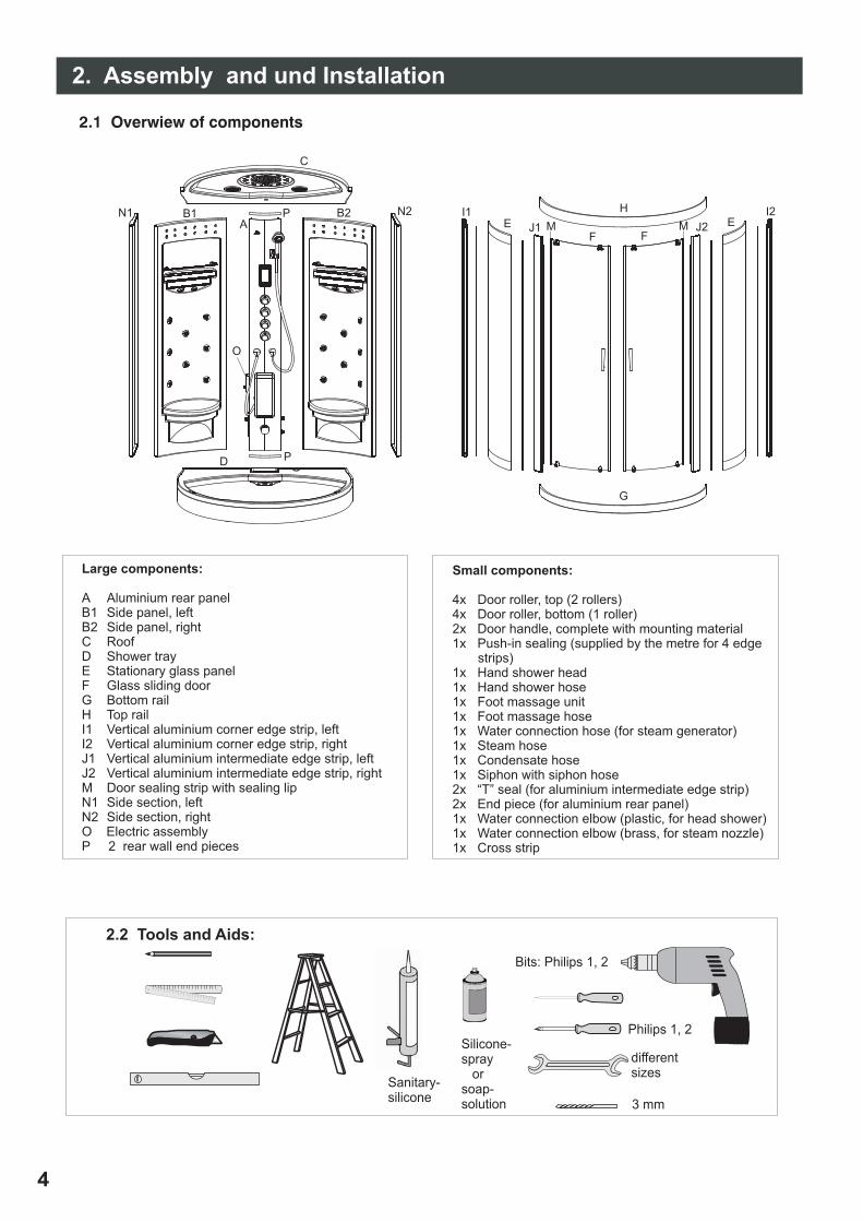
Small components:
4x Door roller, top (2 rollers)4x Door roller, bottom (1 roller)2x Door handle, complete with mounting material1x Push-in sealing (supplied by the metre for 4 edge
strips)1x Hand shower head1x Hand shower hose1x Foot massage unit1x Foot massage hose1x Water connection hose (for steam generator)1x Steam hose1x Condensate hose1x Siphon with siphon hose2x “T” seal (for aluminium intermediate edge strip)2x End piece (for aluminium rear panel)1x Water connection elbow (plastic, for head shower)1x Water connection elbow (brass, for steam nozzle)1x Cross strip
Large components:
A Aluminium rear panelB1 Side panel, leftB2 Side panel, rightC RoofD Shower trayE Stationary glass panelF Glass sliding doorG Bottom railH Top railI1 Vertical aluminium corner edge strip, leftI2 Vertical aluminium corner edge strip, rightJ1 Vertical aluminium intermediate edge strip, leftJ2 Vertical aluminium intermediate edge strip, rightM Door sealing strip with sealing lipN1 Side section, leftN2 Side section, rightO Electric assemblyP 2 rear wall end pieces
A
C
B1 B2P
P
2. Assembly and und Installation
D
E E
F F
G
HI1 I2
J1 J2M MN1 N2
O
2.1 Overwiew of components
Philips 1, 2
differentsizes
Sanitary-silicone
Bits: Philips 1, 2
Silicone-spray
orsoap-solution 3 mm
2.2 Tools and Aids:

5
!
!
!
!
cold
2 x 1/2”
15,5 cm
floor
warm
90
-11
5cm
Water connectionGuidelines
(140 cm)
(110
cm
)
100 cm
20 cm
The floor drainis possible inthe grey area.
2.3 Basic Points
Cubicle Dimensions:
Minimum room height:
2.4 Condition of the floor underneath
2. 5 Water installation
Waste water:
2.6 Electrical connection
142 x 112 x 220 cmThe height of the edge running along the top is 210 cm. The overall height is 220 cm!
225cm
It is extremely important that the shower cubicle be perfectly level when set up! If it is not, this can becorrected by means of the shower tray's adjustable feet. To do this, all feet must be adjusted to the floor underneath(namely at the spot on which the cubicle will be set up permanently). Please work very carefully here(because otherwise there will be a problem with an inclination to shake). When finished, used lock nuts to securethe feet settings.
The floor area should be as even as possible and have the necessary firmness.Coating: waterproof - tiles or synthetic flooring. It is a good idea to have waterproof skirting at the uprightwall (height approx. 10 cm).We urgently recommend that you put in an additional (safety) floor drain(preferably in the area of the shower tray).
The water connection provided by the customer (2 x 1/2 " connections, hot water on the left,cold water on the right, height from the ground: approx.115 cm) should be at the back of thecubicle in the corner area. We urgently recommend planning a separate turning-off facility forthe cubicle. That can either be (5) 2 upstream valves but also corner valves directly as aconnection for the cubicle. Flexible hoses are used for the hot and cold water connectionsfor the shower cubicle and so millimetre precision is not necessary for assemblingthe water feed pipes. This means that is often also possible to connect to anexisting installation without the need for tile work. The water pipes at the backof the steam cubicle are sealed by the manufacturer but they should bechecked again and tightened if necessary. On no account may the flex hosesfor connecting to the household water pipe be squeezed or buckled.Do not forget the 2 “aquastops” on the 2 watersupplies before connecting.
Floor drain preferably in the corner area. Please take theload-bearing system into account, in particular the positions of the feet.Length of the flexible drain hose included in the scope of supply: at least 70 cm.Necessary drain pipe: HT 40, either as pure floor drainage or wall drainage flushwith the floor (special attention must be paid to the leak tightness here becausethere is always a bit of water left in the system). The cubicle's drainage alreadycontains an odour lock.
Important: after mounting the side walls:Do not forget the hose connection between the steam generator and siphon(drainage of residual water from the steam generator).Secure with hose clamps and/or the screw connectors included in the scope of supply.
Only let a qualified electrician do the connection work! Comply with the currently valid electrotechnical rules:particularly D: VDE 0100..., VDE 0100,Part 701, A: ÖVE-EN 1 part 4 § 49..., CH: SN SEV 1000:2005, above all7.01 and/or the valid national rules of the respective country. Please observe the various safety areas outsidethe shower: socket either at least 60 cm to the right beside the shower (seen from the outside) or over theshower, directly in the corner area, at least 230 cm over the floor, i.e. min 20 cm over the edge of the cubicle.
Install the RCCB (residual current circuit breaker) for the mains power line so that it is accessible! Red powerlight on = voltage is applied to the line. If the power light does not go on, press the reset button. The RCCB mustbe tested every 6 months. When the test button is pressed, the light must go out. Press reset again!
Please also bear in mind that once the shower is set up, other products might be prohibited in its direct vicinity(as is the case with every shower): switches, sockets, lights.. (if in doubt, consult an electrician!).
Assembly

6
C.3 The stationary glass panels are inserted intothe grooves of the upright aluminium edge strips.Seal these grooves carefully with silicone beforeinserting the glass panels. Insert the push-insealing from the outside between the glass andthe aluminium edge strip.
C.1 Note that there is a differencebetween the top and the bottomrunner rails and between the right andthe left corner sections! Use 4screws 3.5 x 8.
C. Mount the front aluminium frame.
If necessary, use a small twist drill ( ) to make a pilot hole.3-3,5
Be careful when drilling. Make sure you do not drill through the visible surfaces!
C.2 Push the T sealsinto the grooves of theintermediate aluminiumedge strips.
2.7 Assembly procedures
B. Using a spirit level, carefully align the shower tray at its final installation site. For this purpose, the front panelof the shower tray can be removed. The cover caps on the front of the shower tray are separate and so they canbe taken off for this purpose (adjust the "middle" feet correctly too and secure all settings with the lock-nuts!).
Then move away from the wall again and place it into the "assembly position".
A. Fit the siphon.
Silicone!
Assembly

7
C.4* Mount the front aluminium edge strips.Use 8 screws 3.6 x 25. Here too insert the push-inseal from the outside between the glass and thealuminium edge strip.
C.5 Seal the gap between the stationary glass paneland bottom rail carefully from the inside.
=
=
C.6 Apply silicone to the corners of theshower tray to ensure continuousprotection the whole way round. Thenput the complete aluminium frame ontothe shower tray. Make sure the distancefrom the rear edge of the shower tray iseven.
C.7* Once you have applied a sufficientquantity of silicone onto the shower trayand the aluminium corner edge strips,set up the left rear panel. The plug-inconnection for the light must point towardsthe centre (only difference between rightand left rear panel). Fasten the rear panelto the aluminium corner edge strip with 9screws 3.6 x 14. Use 5 screws M6 x 25,nuts and washers to connect the shower tray.
C.8* Now mount the right rearpanel in the same way.
Silicone!
Assembly
Silicone! Silicone!
Silicone!

C.9* Mount the cabin roof using 10screws M6 x 15, nuts and washersonto the rear panel. The roof mustnow rest on the front rail.
C.10 Fasten the two end pieces tothe aluminium rear panel. Seal thelower end piece with silicone. Nowseal the shower tray in the area ofthe rear panel too.
C.11* Working from the front, insertthe aluminium rear panel into thecabin and align it properly. Use the5-mm drill and drill through the acrylicpanels and aluminium simultaneouslyand screw them together.Make sure that none of the hoses orcables are damaged during boring!
C.12 After drilling take the aluminiumrear panel out again and draw 2 seamsof silicone over the complete length ofthe edge strip (see illustration).
C.13 Insert the aluminium rear panel finally and fix it intoposition with 18 screws M4 x 16, washers and nuts.
C.14* Align the two side sections on theshower tray and drill the side sections andthe acrylic rear panels (3-mm drill)simultaneously. Use 9 screws, each 3.6 x 14,to fix them in position. Now drill the sidesections with the shower tray and fastenthem using 3 screws, each 3.6 x 14.Align the side sections at the roof and drilland screw these also with 3 screws, each3.6 x 14.
8
Assembly
Silicone!
Silicone!

C.15 Fasten the small parts to the cabin rear panel(hand shower, foot massage). Make sure that allscrew connections are sealed carefully with siliconeon the rear panel of the cabin.
9
Mount the door handle
Assembly
Silicone!
E. Hanging the doors
E.1 Hanging the top door runners from the insideinto the upper runner rail.
E.2 Press the bottom door runners with the springdownwards and put the bottom door runnersinto the bottom runner rail.
D. Affix the small parts onto the glass doors.(door handle, top door runners, bottom doorrunners, sealing profile).
Before hanging the doors, put therunners into the highest position!You can use the adjusting screw toalign the doors after hanging them.

10
drain pipe (40mm))
condensat hoseof steam generator
F.1 Mount the electric assembly and connect the leads(light, ventilator, speaker, display, temperature sensor,steam generator).
cold water* hot water*
hand shower
feed nozzles
massage nozzlesleft
connection to thesteam generator
head showermassage nozzlesright
mains connection
steam generator
operating display
ventilator
loud speaker
O3 (not working)
light (head)
light (left and right back wall)
CD/Audio-extension
steam generator
temperature sensor
Bla
uW
eiß
Ro
t
Rot
Rot
antenna
fuse
se
s
1A
3A control unit
steam generator
control unit
steam out
wate
rin
put
(cold
wate
r)w
ate
routp
ut
(to
sip
hon) OFF
OFF
ON
Assembly
Circuit diagramm of E wiring
Silicone!
G1 Establish all other connections:Establish electrical connections in accordance with the circuit diagram / colour marking and/or type of plug.Connect drain, cold water and hot water connections, connect the condensate hose from the steam generatorto the siphon, connect steam hose to steam nozzle and also: hand shower, head shower, massage nozzles.Make sure the seals are inserted before connecting the water!
OFF
* flexible tubesnot including

11
3. Operation
On / Off /pressure controller
thermostatic valve
hand shower
massage-nozzles, left
!
!
50
45 35
30
38
°C
1
2
!
head shower
feed nozzles
OFF
OFF
massage-nozzles, right
ON
Assembly
I. Check pre-assembled hose connections and tighten if necessary!
K. Final inspections: Water: leak-proof test / test for correct functioning.
Electrical power: Protective conductor test, RCCB test, test for correct functioning.
J. Insert the power plug into a 16-ampere-fused shock-proof socket.
L. Affix cover plate onto the back of the rear wall again (see also D.3).
M. Carefully move the cubicle into its final position (2 persons!).
3.1 General points
Children must always be supervised when using a steam shower cubicle. The presence ofadults is always necessary. It is essential that ill, older and fragile people talk to theirdoctor before using the steam shower. Always disconnect from the mains supply afteruse (turn main switch to "off"). If absent for quite a long time, it is recommendable toturn off the water. Keep a safe distance from the steam nozzle (recommended: at least 20 cm- ).Risk of scalding !!! Use only very diluted perfume. Concentrated perfume can destroy
the shower tray..
3.2 "Water settings"
Safety limit to 38°C. Highertemperatures (2) can be set bypressing the safety button (1).(Bear in mind the risk of scalding!)
3.3 Readjusting the doors
Do not hit the door!
The magnet profiles have not beenpermanently secured to the doors.They are easy to readjust should they havebeen slightly displaced during transportation:Start by adjusting the doors to the upperdoor rolls (perpendicular). If the magnetprofiles don't line up all the way to thebottom (light slit), take a small plank (e.g.from the glass protection packaging) andplace it against the outside of the magnetprofile. Carefully tap back into place using asmall hammer.
OFF

Operation
3.4 Cabinet display
12
changeover radio / cd
main switch
scans sation
light on / off
steam on / off
ventilator on / off
Alarm
radio working:volume / station +/-
Mode:
steam generator working:temperature +/-steam time +/-
touch the screen: on

13
Operation
!
!
Switching on
Light functions
Ventilation
Alarm
Radio
Store station
CD (audio) function
Steam generation
Setting the “steam time" and the cubicle temperature
Perfumes
Additional devices
When the power button is pressed, the system starts and the ceiling light goes on.At this point of time the system is in standby mode.
When the system is activated, the light in the top cover and the lights in the panel area can be controlled.In addition, the symbol for light appears on the display. If you wish to switch off the light, press therespective button again.
System turned on: the ventilation can be switched on and off at any time.When switched on, the ventilator symbol appears in the display.
System switched on: alarm can be activated and deactivated. With the acoustic alarm the ventilator canalso be switched on automatically. Turn off again: alarm button + ventilator button.
Press “FM/CD" to activate radio. If a frequency is shown now, the radio is activated.Press “+/-" to vary the frequency / set a stationAdjust volume: Press “Volume" and then “+/-" (from 1-10).
Press “M" briefly to store the adjusted station.Press “M" for a longer time to search for another station.
Press the “FM/CD" button again to switch the audio connection to external devices (CD player, MP3 player...)and the music from these devices will be played over the cubicle amplifier. The “CD” symbol appears on thedisplay. Please make sure that this device is outside the safety distance of 60 cm away from the cubicle(if it is a 230V device). This is not necessary for battery-operated devices.
Press the steam symbol, it appears in the display then and the steam generation begins.Before pressing this symbol, it is essential to ensure that the water supply to the cubicle is open (e.g. after along absence). Otherwise, the steam generator can be destroyed!
The desired time and temperature can be set by means of the steam time and cubicletemperature function. Presetting: 60 minutes and 45°C.First set the steam function and then use “+/-" to adjust the time and temperature.Control range: 0-120 mins, 25-60°C.Keep at a safe distance from the steam nozzle. Risk of scalding!
If perfumes are used, please use only highly-diluted water-soluble products.Perfumes may be very pleasant for people but they can damage the plastic on the shower tray.They may cause discoloration and cracks and the shower might leak.Please therefore act in accordance with the following instructions:The most suitable perfumes are those intended for use in sauna cubicles (special products forsteam showers have been rare up to now). These are exclusively concentrates.Dilution: mix 10ml to a maximum 20ml fragrance solution with 1l of water!Put diluted perfume solution onto a piece of cotton wool and place it into the steam output opening(first pull the cylindrical lid forwards and off). After the fragrance bath, it is essential to remove the cotton woolcarefully and to clean the steam outlet thoroughly with warm water.Oils for aroma lamps are generally not suitable (they contain acids and have only limited water solubility)!Please also pay attention to the consumer information for the respective product!
Under no circumstances may other electric devices (230V) be operated in the cubicle (e.g. electric hairdryer,electric shavers...).
3.5 Discriptions of functions

14
!
!
!
4. Malfunctioning in the electric part
6. Warranty and Service
7. Recycling
5. Maintenance, Care and Cleaning
Safeguards:
1. RCCB in the mains connection line near the shockproof plug: in the event of a fault (failure of the entire electricpart), press reset button. Test. Otherwise check function regularly (twice a year): Press test button. Red "power"pilot light must go out! Press reset again!
2. Overheating protection in the steam generator. If there is a fault, the steam generator will turn off (cause is lackof water). Test and ensure that water can come in. Press reset button at the side of the steam generator (metalcasing on the back wall of the cubicle, in the bottom third) (use a small screwdriver or suchlike).
3. 2 fine-wire fuses in the upper third of the control casing in the back wall of the cubicle: 1 A: if there is a failure,there will be no steam and the display will be turned off. 3 A: If there is a failure, the display will show: "E”, nolight, no steam. If a fuse blows several times in succession, it is essential to consult a qualified specialist!
Please check at least once a year that the cubicle is leak-proof (particularly silicone sealing joints, hoseconnections, waste water system). Always eliminate blockages immediately (checks must also include theconnection between the steam generator and the siphon and the steam nozzle / steam outlet!).
Please use only a damp cloth to clean the surfaces. For stubborn dirt, use a mild, solvent-free and alcohol-freeall-purpose cleaner. Organic solvents and also alcohol can damage the high-quality acrylic surface and evencause cracks. Do not use limescale remover for aluminium parts. Most of this cleaners are inappropriate foraluminium and leave their marks on it (white cords). Under no circumstances may scouring detergents orabrasive sponges be used on the plastic surfaces! To eliminate scratches, use an acrylic polish / acrylic care setsold from a specialist shop..Use only a soft cloth to clean the mirror. Remove dirt with clear water and a wrung-out chamois. Please never usechemical detergents for mirrors (risk of the mirror acquiring “glass disease” from the edge of the mirror).
After each use the shower should be splashed clean with the hand shower and warm water. If perfume was used,please rinse off the nozzle itself and the area around the steam outlet particularly carefully. Then leave the doorsopen until the inside of the cubicle has dried out completely.
We guarantee our products for 2 years. You will find the guarantee certificate on the last page. Spare parts canalso be ordered from our customer service. Please describe the spare part precisely it is best to add the shortdesignation used in this booklet (letter / number) and the exact cubicle type (e.g. Supersteam, article 220015).We always welcome information and suggestions from customers.
The electronic parts of the product must be disposed of in conformance to ElektroG" [law on the distribution,withdrawal and eco-friendly disposal of electrical and electronic devices]. The “waste device” must be brought toan appropriate collecting point. We recommend that you remove the control module, the illumination unit and thedisplay and bring these parts to the electrical/ electronics collecting place. The large remaining parts can behandled as usual (customary local method such as - as bulky waste collection...).
“E

15
Notes

Fax: +49(0)35936 / 36-2222 +49(0)35936 / 36-2281 http://www.jokey.comTel.: +49(0)35936 / 36-0 +49(0)35936 / 36-2265 email: [email protected]. Service:
Fax Service:
Jokey Plastik Sohland GmbH Industriestr. 4 D-02689 Sohland / Spree
Changes / errors excepted.
Quality control No.:
Steam shower cabinet Supersteam Duo GB / 220151 / 04 / 2010
Thank you for the trust you placed in us by purchasing your new steam shower and we shall do everythingin our power not to disappoint you. Before setting up and using the shower, it is essential that you read theassembly instructions and directions for use carefully. Our customer service will be happy to help you if youare uncertain about anything.
Commencement of the guarantee period: purchase date: date on the guarantee certificate or on the salesreceipt. Repairs do not extend the guarantee period.
Guarantee service: Proven manufacturing and material faults will be remedied free of charge during theguarantee period of 2 years. Further claims are excluded.
Claims under guarantee will be accepted if the following conditions are met:
1. This document complete with date of purchase/delivery, company stamp and dealer's signature issubmitted. Complete sales receipts (purchase date, complete address of dealer) will also be accepted.Please also give us the grey “QC field” with manufacturer's stamp (which is on the back of the assemblyinstructions) or a copy of it. It is very important for the work in our quality assurance department.In addition, if a claim is being raised, concrete information on the type of damage / fault will be required.
2. Transport the shower carefully! (prevent falls or warping!).3. Unpack the product carefully after purchase. Please tell the dealer if you find any faults and you will then
be given a replacement quickly. Please do not use any obviously defective parts when assembling.Otherwise, you will lose the entitlement to a claim under guarantee.
4. Water connection: minimum pressure is 0.3 Mpa and maximum is 0.4 MPa water hardness: If the wateris harder than 10°dH, we urgently recommend a softening plant / lime converter.Damage caused by heavy limescale will not be covered by guarantee! Please install “aquastops”at the water connections (warm and cold). This is a protection against tube bursting!
5. The shower may only be installed by a specialist (sanitary plumber / electrician).6. Do not temper with the device itself (control electronics...).7. Mistakes in erection are not covered by guarantee, it is essential to follow the assembly instructions, in
particular the instructions with safety signs. In particular, make sure that all connections are leakproof.8. The shower cubicle must be set up on a waterproof floor. If set up on a leaky floor, no liability will be
accepted for damage caused by water / consequential damage.Fitting an additional safety water drain in the area of the shower tray is urgently recommended.
9. ”Second-hand products" will not be covered under guarantee.10. Damage due to concentrated perfume solutions will not be covered under guarantee.11. Do not permanently install or wall in the shower cubicle. The rear side(s) must remain accessible for
checking purposes (it must be possible to move it forwards )12. Only use original spare parts for repairs.
____________________________Type of steam shower Stamp of trader
____________________________ ________________________Place, date Signature of trader
GUARANTEE CERTIFICATE STEAM SHOWER 2 YEARS' GUARANTEE
SUPERSTEAMsingle
quadlightline
eco colorduo