steam trap overview
DESCRIPTION
Steam Trap details and overviewTRANSCRIPT
Steam Trapping an overview
mechanicals o l u t i o n s
2 3
Steam trapping solutions
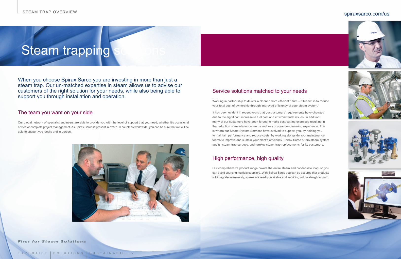
When you choose Spirax Sarco you are investing in more than just a steam trap. Our un-matched expertise in steam allows us to advise our customers of the right solution for your needs, while also being able to support you through installation and operation.
The team you want on your side
Our global network of specialist engineers are able to provide you with the level of support that you need, whether it’s occasional advice or complete project management. As Spirax Sarco is present in over 100 countries worldwide, you can be sure that we will be able to support you locally and in person.
spiraxsarco.com/usSTEAM TRAP OVERVIEW
Service solutions matched to your needs
Working in partnership to deliver a cleaner more efficient future – ‘Our aim is to reduce your total cost of ownership through improved efficiency of your steam system.’
It has been evident in recent years that our customers’ requirements have changed due to the significant increase in fuel cost and environmental issues. In addition, many of our customers have been forced to make cost cutting exercises resulting in the reduction of maintenance teams and loss of steam engineering experience. This is where our Steam System Services have evolved to support you, by helping you to maintain performance and reduce costs, by working alongside your maintenance teams to improve and sustain your plant’s efficiency. Spirax Sarco offers steam system audits, steam trap surveys, and turnkey steam trap replacements for its customers.
High performance, high quality
Our comprehensive product range covers the entire steam and condensate loop, so you can avoid sourcing multiple suppliers. With Spirax Sarco you can be assured that products will integrate seamlessly, spares are readily available and servicing will be straightforward.
4 5
spiraxsarco.com/usSTEAM TRAP OVERVIEW
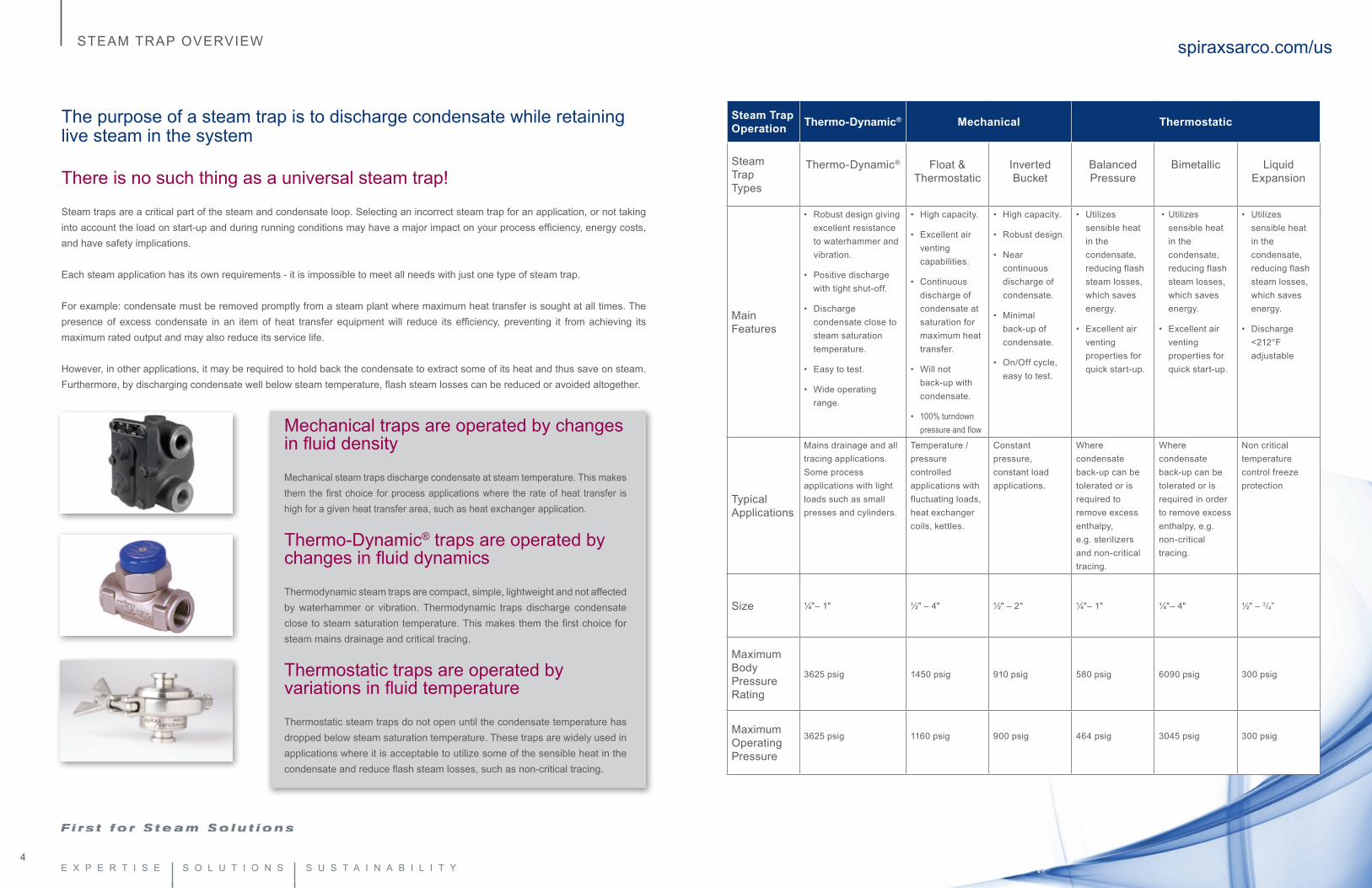
The purpose of a steam trap is to discharge condensate while retaining live steam in the system
There is no such thing as a universal steam trap!
Steam traps are a critical part of the steam and condensate loop. Selecting an incorrect steam trap for an application, or not taking into account the load on start-up and during running conditions may have a major impact on your process efficiency, energy costs, and have safety implications.
Each steam application has its own requirements - it is impossible to meet all needs with just one type of steam trap.
For example: condensate must be removed promptly from a steam plant where maximum heat transfer is sought at all times. The presence of excess condensate in an item of heat transfer equipment will reduce its efficiency, preventing it from achieving its maximum rated output and may also reduce its service life.
However, in other applications, it may be required to hold back the condensate to extract some of its heat and thus save on steam. Furthermore, by discharging condensate well below steam temperature, flash steam losses can be reduced or avoided altogether.
Mechanical traps are operated by changes in fluid density
Mechanical steam traps discharge condensate at steam temperature. This makes them the first choice for process applications where the rate of heat transfer is high for a given heat transfer area, such as heat exchanger application.
Thermo-Dynamic® traps are operated by changes in fluid dynamics
Thermodynamic steam traps are compact, simple, lightweight and not affected by waterhammer or vibration. Thermodynamic traps discharge condensate close to steam saturation temperature. This makes them the first choice for steam mains drainage and critical tracing.
Thermostatic traps are operated by variations in fluid temperature
Thermostatic steam traps do not open until the condensate temperature has dropped below steam saturation temperature. These traps are widely used in applications where it is acceptable to utilize some of the sensible heat in the condensate and reduce flash steam losses, such as non-critical tracing.
Steam Trap Operation Thermo-Dynamic® Mechanical Thermostatic
SteamTrap Types
Thermo-Dynamic® Float & Thermostatic
Inverted Bucket
Balanced Pressure
Bimetallic Liquid Expansion
Main Features
• Robust design giving excellent resistance to waterhammer and vibration.
• Positive discharge with tight shut-off.
• Discharge condensate close to steam saturation temperature.
• Easy to test.
• Wide operating range.
• High capacity.
• Excellent air venting capabilities.
• Continuous discharge of condensate at saturation for maximum heat transfer.
• Will not back-up with condensate.
• 100% turndown pressure and flow
• High capacity.
• Robust design.
• Near continuous discharge of condensate.
• Minimal back-up of condensate.
• On/Off cycle, easy to test.
• Utilizes sensible heat in the condensate, reducing flash steam losses, which saves energy.
• Excellent air venting properties for quick start-up.
• Utilizes sensible heat in the condensate, reducing flash steam losses, which saves energy.
• Excellent air venting properties for quick start-up.
• Utilizes sensible heat in the condensate, reducing flash steam losses, which saves energy.
• Discharge <212°F adjustable
Typical Applications
Mains drainage and all tracing applications.Some process applications with light loads such as small presses and cylinders.
Temperature / pressure controlled applications with fluctuating loads, heat exchanger coils, kettles.
Constant pressure, constant load applications.
Where condensate back-up can be tolerated or is required to remove excess enthalpy,e.g. sterilizers and non-critical tracing.
Where condensate back-up can be tolerated or is required in order to remove excess enthalpy, e.g. non-critical tracing.
Non critical temperature control freeze protection
Size ¼"– 1" ½" – 4" ½" – 2" ¼"– 1" ¼"– 4" ½" – 3/4”
MaximumBodyPressureRating
3625 psig 1450 psig 910 psig 580 psig 6090 psig 300 psig
Maximum Operating Pressure
3625 psig 1160 psig 900 psig 464 psig 3045 psig 300 psig
6 7
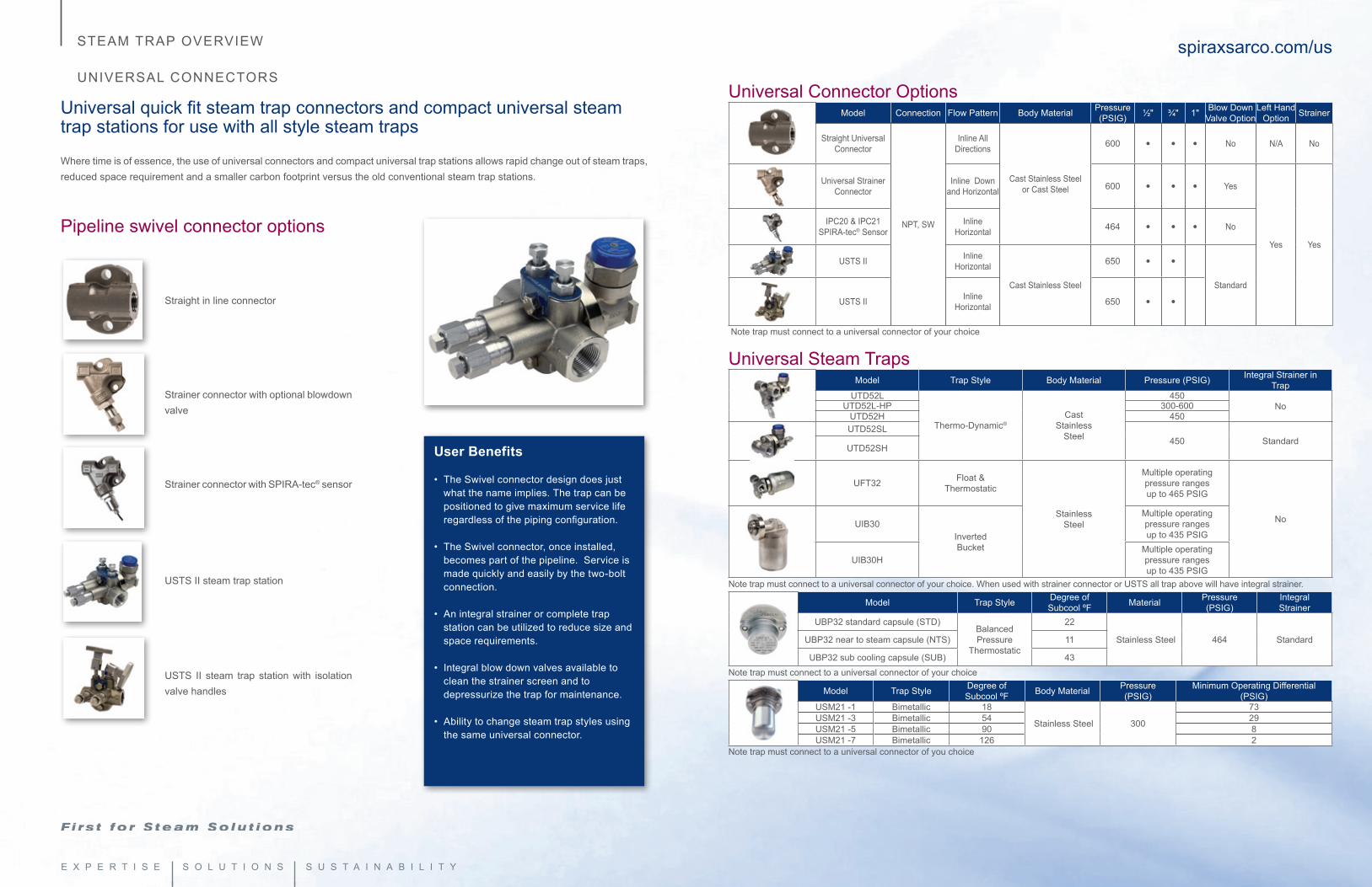
Universal quick fit steam trap connectors and compact universal steam trap stations for use with all style steam traps
Where time is of essence, the use of universal connectors and compact universal trap stations allows rapid change out of steam traps, reduced space requirement and a smaller carbon footprint versus the old conventional steam trap stations.
Pipeline swivel connector options
spiraxsarco.com/usSTEAM TRAP OVERVIEW
UNIVERSAL CONNECTORS Universal Connector Options
Model Connection Flow Pattern Body Material Pressure (PSIG) ½" ¾" 1" Blow Down
Valve OptionLeft Hand
Option Strainer
Straight Universal Connector
NPT, SW
Inline All Directions
Cast Stainless Steel or Cast Steel
600 • • • No N/A No
Universal Strainer Connector
Inline Down and Horizontal 600 • • • Yes
Yes Yes
IPC20 & IPC21 SPIRA-tec® Sensor
Inline Horizontal 464 • • • No
USTS II Inline Horizontal
Cast Stainless Steel
650 • •
Standard
USTS II Inline Horizontal 650 • •
Note trap must connect to a universal connector of your choice
Universal Steam TrapsModel Trap Style Body Material Pressure (PSIG) Integral Strainer in
TrapUTD52L
Thermo-Dynamic®Cast
Stainless Steel
450NoUTD52L-HP 300-600
UTD52H 450UTD52SL
450 StandardUTD52SH
UFT32 Float & Thermostatic
Stainless Steel
Multiple operating pressure rangesup to 465 PSIG
NoUIB30Inverted Bucket
Multiple operating pressure rangesup to 435 PSIG
UIB30HMultiple operating pressure rangesup to 435 PSIG
Note trap must connect to a universal connector of your choice. When used with strainer connector or USTS all trap above will have integral strainer.
Model Trap Style Degree of Subcool ºF Material Pressure
(PSIG)Integral Strainer
UBP32 standard capsule (STD)Balanced Pressure
Thermostatic
22
Stainless Steel 464 StandardUBP32 near to steam capsule (NTS) 11
UBP32 sub cooling capsule (SUB) 43Note trap must connect to a universal connector of your choice
Model Trap Style Degree of Subcool ºF Body Material Pressure
(PSIG) Minimum Operating Differential
(PSIG)USM21 -1 Bimetallic 18
Stainless Steel 300
73USM21 -3 Bimetallic 54 29USM21 -5 Bimetallic 90 8USM21 -7 Bimetallic 126 2
Note trap must connect to a universal connector of you choice
User Benefits
• The Swivel connector design does just what the name implies. The trap can be positioned to give maximum service life regardless of the piping configuration.
• The Swivel connector, once installed, becomes part of the pipeline. Service is made quickly and easily by the two-bolt connection.
• An integral strainer or complete trap station can be utilized to reduce size and space requirements.
• Integral blow down valves available to clean the strainer screen and to depressurize the trap for maintenance.
• Ability to change steam trap styles using the same universal connector.
Straight in line connector
Strainer connector with optional blowdown valve
Strainer connector with SPIRA-tec® sensor
USTS II steam trap station
USTS II steam trap station with isolation valve handles
8 9
The world’s FIRST Thermo-Dynamic® disc trap is still the worlds BEST
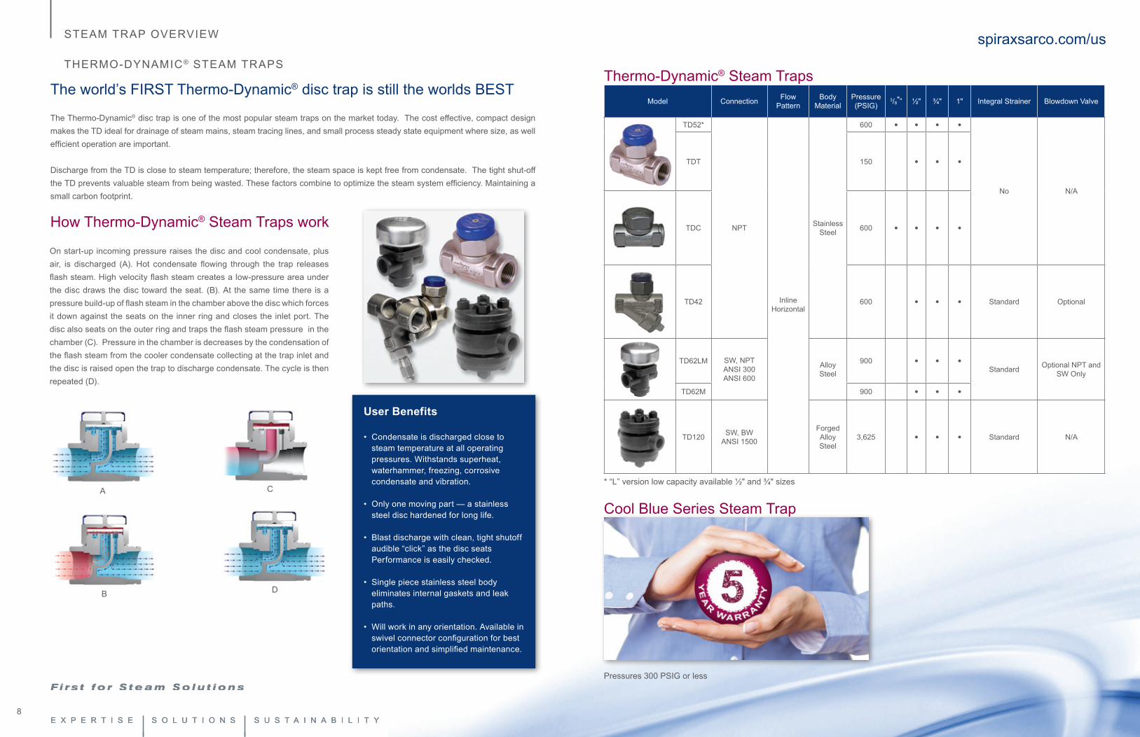
The Thermo-Dynamic® disc trap is one of the most popular steam traps on the market today. The cost effective, compact design makes the TD ideal for drainage of steam mains, steam tracing lines, and small process steady state equipment where size, as well efficient operation are important.
Discharge from the TD is close to steam temperature; therefore, the steam space is kept free from condensate. The tight shut-off the TD prevents valuable steam from being wasted. These factors combine to optimize the steam system efficiency. Maintaining a small carbon footprint.
How Thermo-Dynamic® Steam Traps work
On start-up incoming pressure raises the disc and cool condensate, plus air, is discharged (A). Hot condensate flowing through the trap releases flash steam. High velocity flash steam creates a low-pressure area under the disc draws the disc toward the seat. (B). At the same time there is a pressure build-up of flash steam in the chamber above the disc which forces it down against the seats on the inner ring and closes the inlet port. The disc also seats on the outer ring and traps the flash steam pressure in the chamber (C). Pressure in the chamber is decreases by the condensation of the flash steam from the cooler condensate collecting at the trap inlet and the disc is raised open the trap to discharge condensate. The cycle is then repeated (D).
A
B
C
D
spiraxsarco.com/usSTEAM TRAP OVERVIEW
THERMO-DYNAMIC® STEAM TRAPS
User Benefits
• Condensate is discharged close to steam temperature at all operating pressures. Withstands superheat, waterhammer, freezing, corrosive condensate and vibration.
• Only one moving part — a stainless steel disc hardened for long life.
• Blast discharge with clean, tight shutoff audible “click” as the disc seats Performance is easily checked.
• Single piece stainless steel body eliminates internal gaskets and leak paths.
• Will work in any orientation. Available in swivel connector configuration for best orientation and simplified maintenance.
Thermo-Dynamic® Steam Traps Model Connection Flow
PatternBody
MaterialPressure (PSIG)
3/8"” ½" ¾" 1" Integral Strainer Blowdown Valve
TD52*
NPT
InlineHorizontal
Stainless Steel
600 • • • •
No N/A
TDT 150 • • •
TDC 600 • • • •
TD42 600 • • • Standard Optional
TD62LM SW, NPTANSI 300ANSI 600
Alloy Steel
900 • • •Standard Optional NPT and
SW Only
TD62M 900 • • •
TD120 SW, BWANSI 1500
Forged Alloy Steel
3,625 • • • Standard N/A
* “L” version low capacity available ½" and ¾" sizes
Cool Blue Series Steam Trap
Pressures 300 PSIG or less
10 11
spiraxsarco.com/usSTEAM TRAP OVERVIEW
MECHANICAL
User Benefits
• Immediate condensate discharge with clean, tight shut-off. No back-up of condensate ensures maximum plant efficiency and heat output to the process.
• Works efficiently on both heavy and light loads with no passage of live steam.
• Not affected by wide and sudden fluctuations of pressure or flow rate.
• Infinite turndown ratio.
• Stainless steel internals that can tolerate corrosive condensate.
• Integral air vent to ensure rapid warm-up of plant.
• Robust construction to guarantee long life against waterhammer and vibration.
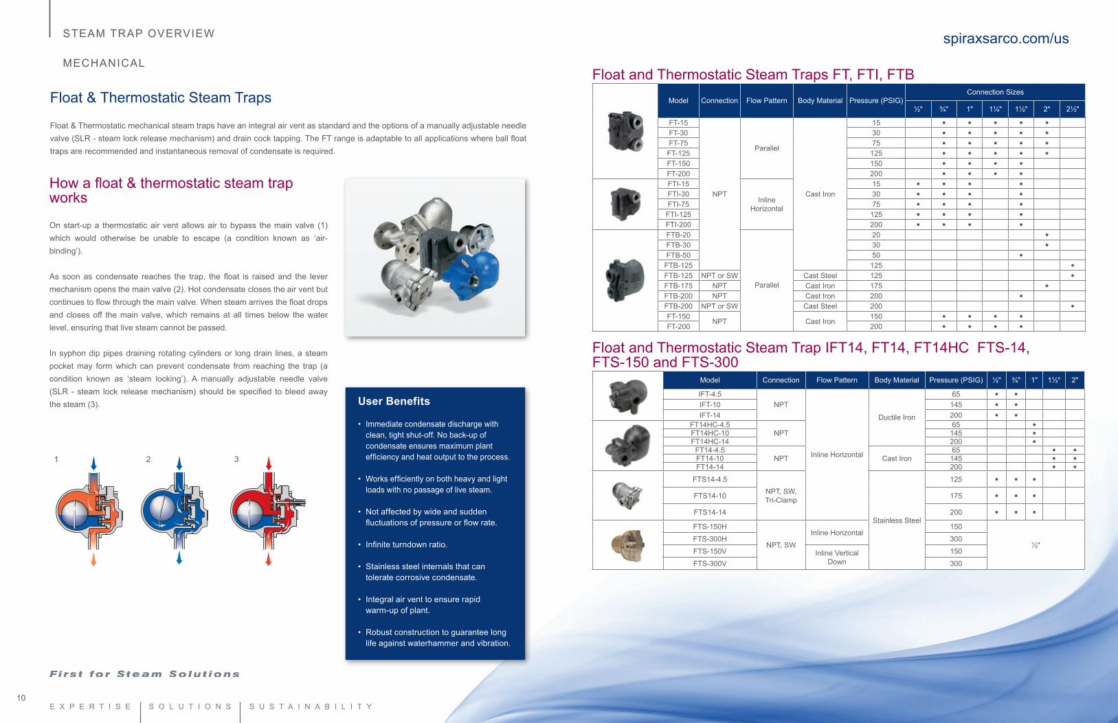
Float & Thermostatic Steam Traps
Float & Thermostatic mechanical steam traps have an integral air vent as standard and the options of a manually adjustable needle valve (SLR - steam lock release mechanism) and drain cock tapping. The FT range is adaptable to all applications where ball float traps are recommended and instantaneous removal of condensate is required.
How a float & thermostatic steam trap works
On start-up a thermostatic air vent allows air to bypass the main valve (1) which would otherwise be unable to escape (a condition known as ‘air-binding’).
As soon as condensate reaches the trap, the float is raised and the lever mechanism opens the main valve (2). Hot condensate closes the air vent but continues to flow through the main valve. When steam arrives the float drops and closes off the main valve, which remains at all times below the water level, ensuring that live steam cannot be passed.
In syphon dip pipes draining rotating cylinders or long drain lines, a steam pocket may form which can prevent condensate from reaching the trap (a condition known as ‘steam locking’). A manually adjustable needle valve (SLR - steam lock release mechanism) should be specified to bleed away the steam (3).
1 2 3
Float and Thermostatic Steam Traps FT, FTI, FTBModel Connection Flow Pattern Body Material Pressure (PSIG)
Connection Sizes
½" ¾" 1" 1¼" 1½" 2" 2½"
FT-15
NPT
Parallel
Cast Iron
15 • • • • •FT-30 30 • • • • •FT-75 75 • • • • •
FT-125 125 • • • • •FT-150 150 • • • •FT-200 200 • • • •FTI-15
Inline Horizontal
15 • • • •FTI-30 30 • • • •FTI-75 75 • • • •
FTI-125 125 • • • •FTI-200 200 • • • •FTB-20
Parallel
20 •FTB-30 30 •FTB-50 50 •
FTB-125 125 •FTB-125 NPT or SW Cast Steel 125 •FTB-175 NPT Cast Iron 175 •FTB-200 NPT Cast Iron 200 •FTB-200 NPT or SW Cast Steel 200 •FT-150
NPT Cast Iron150 • • • •
FT-200 200 • • • •
Float and Thermostatic Steam Trap IFT14, FT14, FT14HC FTS-14, FTS-150 and FTS-300
Model Connection Flow Pattern Body Material Pressure (PSIG) ½" ¾" 1" 1½" 2"
IFT-4.5NPT
Inline Horizontal
Ductile Iron
65 • •IFT-10 145 • •IFT-14 200 • •
FT14HC-4.5NPT
65 •FT14HC-10 145 •FT14HC-14 200 •
FT14-4.5NPT Cast Iron
65 • •FT14-10 145 • •FT14-14 200 • •
FTS14-4.5NPT, SW,Tri-Clamp
Stainless Steel
125 • • •FTS14-10 175 • • •FTS14-14 200 • • •FTS-150H
NPT, SW
Inline Horizontal150
½"FTS-300H 300
FTS-150V Inline Vertical Down
150
FTS-300V 300
12 13
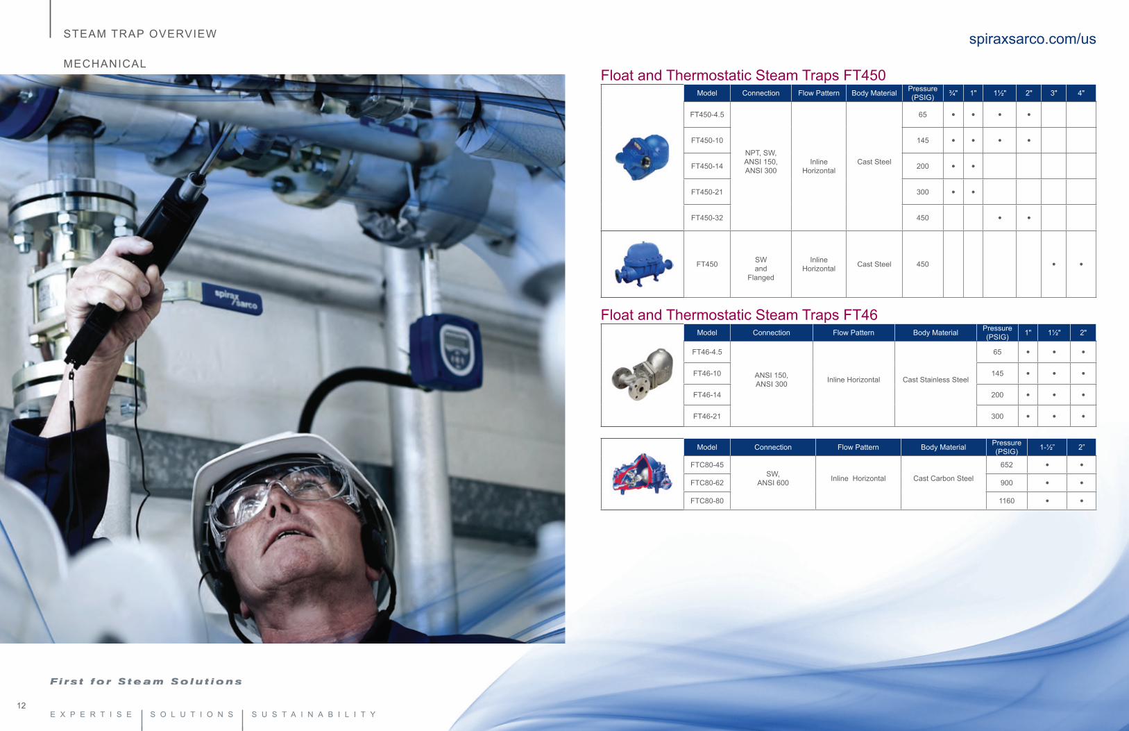
Float and Thermostatic Steam Traps FT450Model Connection Flow Pattern Body Material Pressure
(PSIG) ¾" 1" 1½" 2" 3" 4"
FT450-4.5
NPT, SW, ANSI 150, ANSI 300
Inline Horizontal
Cast Steel
65 • • • •
FT450-10 145 • • • •
FT450-14 200 • •
FT450-21 300 • •
FT450-32 450 • •
FT450 SW and
Flanged
Inline Horizontal Cast Steel 450 • •
Float and Thermostatic Steam Traps FT46Model Connection Flow Pattern Body Material Pressure
(PSIG) 1" 1½" 2"
FT46-4.5
ANSI 150, ANSI 300 Inline Horizontal Cast Stainless Steel
65 • • •
FT46-10 145 • • •
FT46-14 200 • • •
FT46-21 300 • • •
Model Connection Flow Pattern Body Material Pressure (PSIG) 1-½” 2”
FTC80-45SW,
ANSI 600 Inline Horizontal Cast Carbon Steel
652 • •FTC80-62 900 • •FTC80-80 1160 • •
spiraxsarco.com/usSTEAM TRAP OVERVIEW
MECHANICAL
14 15
spiraxsarco.com/usSTEAM TRAP OVERVIEW
MECHANICAL STEAM TRAPS
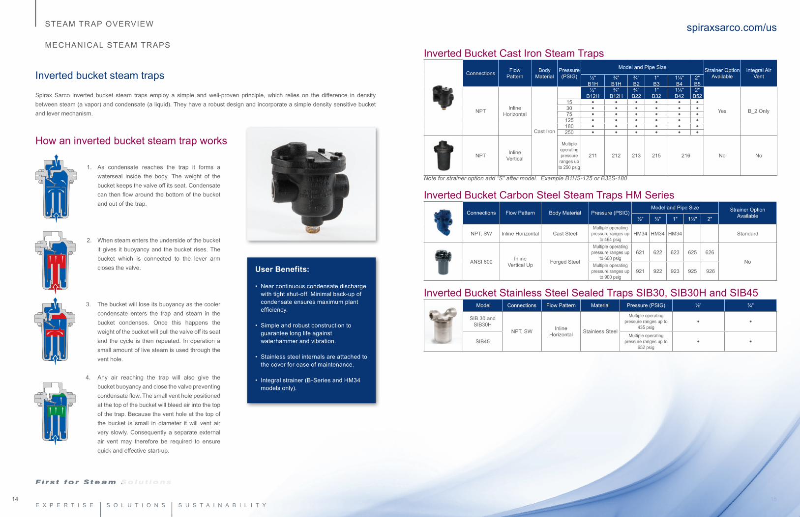
Inverted bucket steam traps
Spirax Sarco inverted bucket steam traps employ a simple and well-proven principle, which relies on the difference in density between steam (a vapor) and condensate (a liquid). They have a robust design and incorporate a simple density sensitive bucket and lever mechanism.
How an inverted bucket steam trap works
1. As condensate reaches the trap it forms a waterseal inside the body. The weight of the bucket keeps the valve off its seat. Condensate can then flow around the bottom of the bucket and out of the trap.
2. When steam enters the underside of the bucket it gives it buoyancy and the bucket rises. The bucket which is connected to the lever arm closes the valve.
3. The bucket will lose its buoyancy as the cooler condensate enters the trap and steam in the bucket condenses. Once this happens the weight of the bucket will pull the valve off its seat and the cycle is then repeated. In operation a small amount of live steam is used through the vent hole.
4. Any air reaching the trap will also give the bucket buoyancy and close the valve preventing condensate flow. The small vent hole positioned at the top of the bucket will bleed air into the top of the trap. Because the vent hole at the top of the bucket is small in diameter it will vent air very slowly. Consequently a separate external air vent may therefore be required to ensure quick and effective start-up.
User Benefits:
• Near continuous condensate discharge with tight shut-off. Minimal back-up of condensate ensures maximum plant efficiency.
• Simple and robust construction to guarantee long life against waterhammer and vibration.
• Stainless steel internals are attached to the cover for ease of maintenance.
• Integral strainer (B-Series and HM34 models only).
Inverted Bucket Cast Iron Steam Traps
Connections Flow Pattern
BodyMaterial
Pressure (PSIG)
Model and Pipe Size Strainer Option Available
Integral Air Vent½"
B1H¾"
B1H¾" B2
1" B3
1¼" B4
2" B5
NPT InlineHorizontal
Cast Iron
½"B12H
¾" B12H
¾" B22
1" B32
1¼" B42
2" B52
Yes B_2 Only
15 • • • • • •30 • • • • • •75 • • • • • •
125 • • • • • •180 • • • • • •250 • • • • • •
NPT InlineVertical
Multiple operating pressure
ranges up to 250 psig
211 212 213 215 216 No No
Note for strainer option add “S” after model. Example B1HS-125 or B32S-180
Inverted Bucket Carbon Steel Steam Traps HM SeriesConnections Flow Pattern Body Material Pressure (PSIG)
Model and Pipe Size Strainer Option Available½" ¾" 1" 1½" 2"
NPT, SW Inline Horizontal Cast SteelMultiple operating
pressure ranges up to 464 psig
HM34 HM34 HM34 Standard
ANSI 600 Inline Vertical Up Forged Steel
Multiple operating pressure ranges up
to 600 psig621 622 623 625 626
NoMultiple operating
pressure ranges up to 900 psig
921 922 923 925 926
Inverted Bucket Stainless Steel Sealed Traps SIB30, SIB30H and SIB45 Model Connections Flow Pattern Material Pressure (PSIG) ½" ¾"
SIB 30 and SIB30H
NPT, SW InlineHorizontal Stainless Steel
Multiple operating pressure ranges up to
435 psig• •
SIB45Multiple operating
pressure ranges up to 652 psig
• •
16 17
spiraxsarco.com/usSTEAM TRAP OVERVIEW
THERMOSTATIC STEAM TRAPS
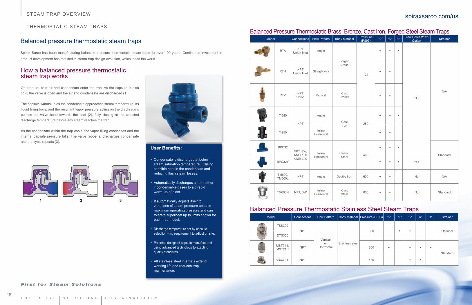
Balanced pressure thermostatic steam traps
Spirax Sarco has been manufacturing balanced pressure thermostatic steam traps for over 100 years. Continuous investment in
product development has resulted in steam trap design evolution, which leads the world.
How a balanced pressure thermostatic
1 2 3
steam trap works
On start-up, cold air and condensate enter the trap. As the capsule is also cold, the valve is open and the air and condensate are discharged (1).
The capsule warms up as the condensate approaches steam temperature. Its liquid filling boils, and the resultant vapor pressure acting on the diaphragms pushes the valve head towards the seat (2), fully closing at the selected discharge temperature before any steam reaches the trap.
As the condensate within the trap cools, the vapor filling condenses and the internal capsule pressure falls. The valve reopens, discharges condensate and the cycle repeats (3).
Balanced Pressure Thermostatic Brass, Bronze, Cast Iron, Forged Steel Steam TrapsModel Connections Flow Pattern Body Material Pressure
(PSIG) ½" ¾" 1" Blow Down Valve Option Strainer
RTA NPTUnion Inlet Angle
Forged Brass
125
• • •
No
N/A
RTH NPTUnion Inlet Straightway • •
RTV NPT Union Vertical Cast
Bronze • •
T-250
NPT
Angle
Cast Iron 250
• • •
T-250 Inline Horizontal • •
BPC32NPT, SW,ANSI 150ANSI 300
Inline Horizontal
Carbon Steel 465
• • •Standard
BPC32Y • • • Yes
TM600, TM600L NPT Angle Ductile Iron 600 • • No N/A
TM600N NPT, SW Inline Horizontal
CastSteel 600 • • No Standard
Balanced Pressure Thermostatic Stainless Steel Steam TrapsModel Connections Flow Pattern Body Material Pressure (PSIG) ¼" 3/8" ½" ¾" 1" Strainer
TSS300
NPT
Verticalor
HorizontalStainless steel
300 • • OptionalDTS300
MST21 & MST21H NPT 300 • • • •
Standard
SBC30LC NPT 435 • •
User Benefits:
• Condensate is discharged at below steam saturation temperature, utilising sensible heat in the condensate and reducing flash steam losses.
• Automatically discharges air and other incondensable gases to aid rapid warm-up of plant.
• It automatically adjusts itself to variations of steam pressure up to its maximum operating pressure and can tolerate superheat up to limits shown for each trap model.
• Discharge temperature set by capsule selection – no requirement to adjust on site.
• Patented design of capsule manufactured using advanced technology to exacting quality standards.
• All stainless steel internals extend working life and reduces trap maintenance.
18 19
spiraxsarco.com/usSTEAM TRAP OVERVIEW
THERMOSTATIC STEAM TRAPS
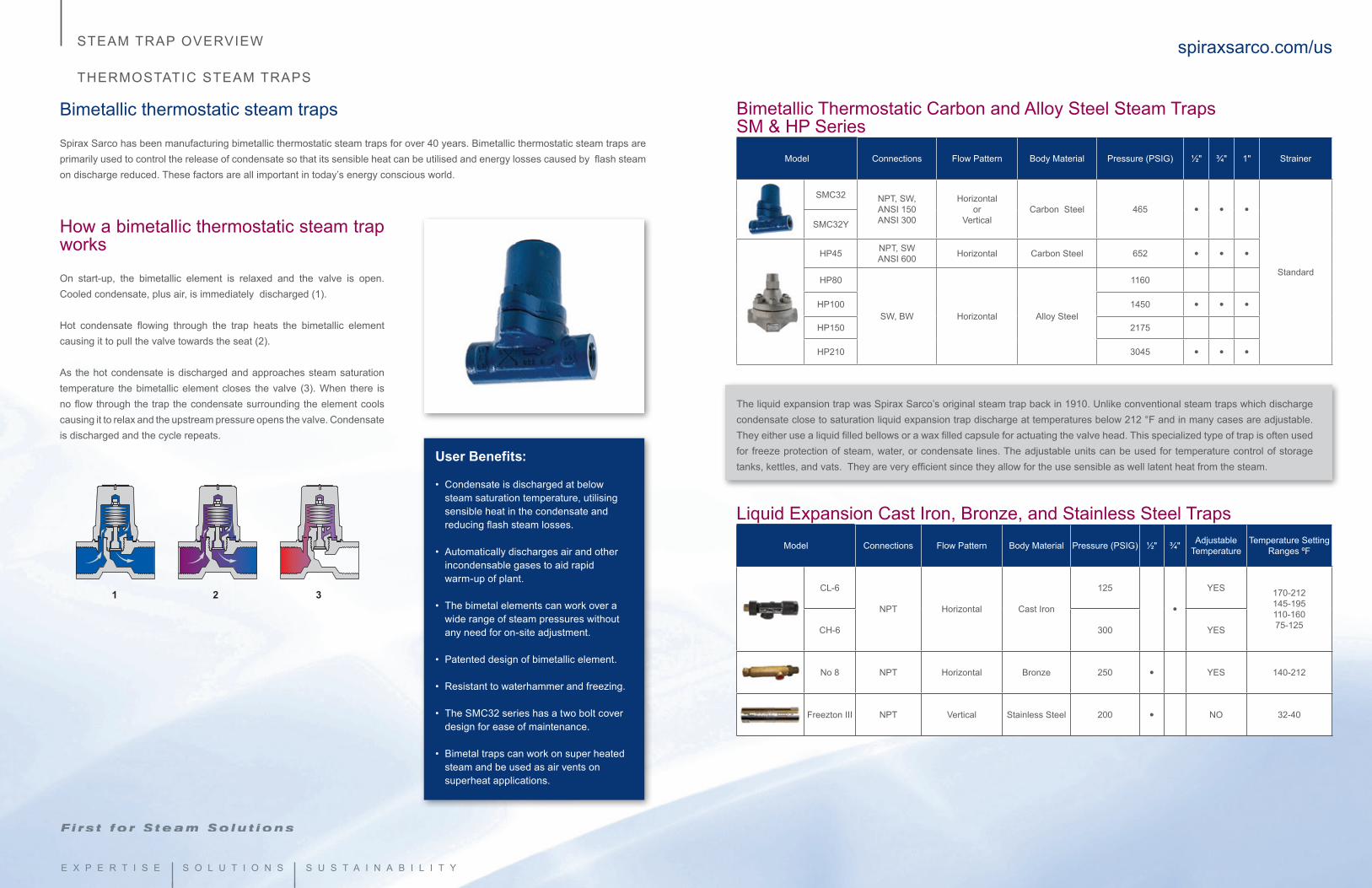
Bimetallic thermostatic steam traps
Spirax Sarco has been manufacturing bimetallic thermostatic steam traps for over 40 years. Bimetallic thermostatic steam traps are primarily used to control the release of condensate so that its sensible heat can be utilised and energy losses caused by flash steam on discharge reduced. These factors are all important in today’s energy conscious world.
How a bimetallic thermostatic steam trap works
On start-up, the bimetallic element is relaxed and the valve is open. Cooled condensate, plus air, is immediately discharged (1).
Hot condensate flowing through the trap heats the bimetallic element causing it to pull the valve towards the seat (2).
As the hot condensate is discharged and approaches steam saturation temperature the bimetallic element closes the valve (3). When there is no flow through the trap the condensate surrounding the element cools causing it to relax and the upstream pressure opens the valve. Condensate is discharged and the cycle repeats.
1 2 3
User Benefits:
• Condensate is discharged at below steam saturation temperature, utilising sensible heat in the condensate and reducing flash steam losses.
• Automatically discharges air and other incondensable gases to aid rapid warm-up of plant.
• The bimetal elements can work over a wide range of steam pressures without any need for on-site adjustment.
• Patented design of bimetallic element.
• Resistant to waterhammer and freezing.
• The SMC32 series has a two bolt cover design for ease of maintenance.
• Bimetal traps can work on super heated steam and be used as air vents on superheat applications.
Bimetallic Thermostatic Carbon and Alloy Steel Steam TrapsSM & HP Series
Model Connections Flow Pattern Body Material Pressure (PSIG) ½" ¾" 1" Strainer
SMC32 NPT, SW, ANSI 150ANSI 300
Horizontalor
VerticalCarbon Steel 465 • • •
Standard
SMC32Y
HP45 NPT, SWANSI 600 Horizontal Carbon Steel 652 • • •
HP80
SW, BW Horizontal Alloy Steel
1160
HP100 1450 • • •HP150 2175
HP210 3045 • • •
The liquid expansion trap was Spirax Sarco’s original steam trap back in 1910. Unlike conventional steam traps which discharge condensate close to saturation liquid expansion trap discharge at temperatures below 212 °F and in many cases are adjustable. They either use a liquid filled bellows or a wax filled capsule for actuating the valve head. This specialized type of trap is often used for freeze protection of steam, water, or condensate lines. The adjustable units can be used for temperature control of storage tanks, kettles, and vats. They are very efficient since they allow for the use sensible as well latent heat from the steam.
Liquid Expansion Cast Iron, Bronze, and Stainless Steel TrapsModel Connections Flow Pattern Body Material Pressure (PSIG) ½" ¾" Adjustable
Temperature Temperature Setting
Ranges ºF
CL-6
NPT Horizontal Cast Iron
125
•
YES 170-212145-195110-16075-125CH-6 300 YES
No 8 NPT Horizontal Bronze 250 • YES 140-212
Freezton III NPT Vertical Stainless Steel 200 • NO 32-40
20 21
spiraxsarco.com/usSTEAM TRAP OVERVIEW
THERMOSTATIC STEAM TRAPS
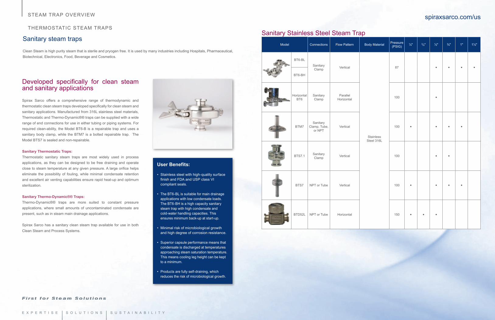
Sanitary steam traps
Clean Steam is high purity steam that is sterile and pryogen free. It is used by many industries including Hospitals, Pharmaceutical, Biotechnical, Electronics, Food, Beverage and Cosmetics.
Developed specifically for clean steam and sanitary applications
Spirax Sarco offers a comprehensive range of thermodynamic and thermostatic clean steam traps developed specifically for clean steam and sanitary applications. Manufactured from 316L stainless steel materials, Thermostatic and Thermo-Dynamic®® traps can be supplied with a wide range of end connections for use in either tubing or piping systems. For required clean-ability, the Model BT6-B is a repairable trap and uses a sanitary body clamp, while the BTM7 is a bolted repairable trap. The Model BTS7 is sealed and non-repairable. Sanitary Thermostatic Traps: Thermostatic sanitary steam traps are most widely used in process applications, as they can be designed to be free draining and operate close to steam temperature at any given pressure. A large orifice helps eliminate the possibility of fouling, while minimal condensate retention and excellent air venting capabilities ensure rapid heat-up and optimum sterilization.
Sanitary Thermo-Dynamic®® Traps: Thermo-Dynamic®® traps are more suited to constant pressure applications, where small amounts of uncontaminated condensate are present, such as in steam main drainage applications.
Spirax Sarco has a sanitary clean steam trap available for use in both Clean Steam and Process Systems.
User Benefits:
• Stainless steel with high-quality surface finish and FDA and USP class VI compliant seals.
• The BT6-BL is suitable for main drainage applications with low condensate loads. The BT6-BH is a high capacity sanitary steam trap with high condensate and cold-water handling capacities. This ensures minimum back-up at start-up.
• Minimal risk of microbiological growth and high degree of corrosion resistance.
• Superior capsule performance means that condensate is discharged at temperatures approaching steam saturation temperature. This means cooling leg height can be kept to a minimum.
• Products are fully self-draining, which reduces the risk of microbiological growth.
Sanitary Stainless Steel Steam TrapModel Connections Flow Pattern Body Material Pressure
(PSIG) ¼" 3/8" ½" ¾" 1" 1½"
BT6-BL
Sanitary Clamp Vertical
StainlessSteel 316L
87 • • • •BT6-BH
HorizontalBT6
Sanitary Clamp
ParallelHorizontal 100 •
BTM7Sanitary
Clamp, Tube, or NPT
Vertical 100 • • • •
BTS7.1 Sanitary Clamp Vertical 100 • •
BTS7 NPT or Tube Vertical 100 • • • •
BTD52L NPT or Tube Horizontal 150 • • •
22 23
User Benefits:
• Immediate indication of ‘correct operation’, ‘trap waterlogged’ or trap ‘leaking steam’.
• Trap status indicated by colored lights - no skilled labor needed.
• Separate chambers or integral sensor options to suit all steam trap system applications.
• Compatible with BEMS/EMS/SCADA system for efficient system monitoring.
• Reduced energy losses and improved system efficiency leading to increased profits.
• Remote test points allow inaccessible traps to be monitored during trap surveys.
spiraxsarco.com/usSTEAM TRAP OVERVIEW
SPIRA-tec® STEAM TRAP MONITORING SYSTEM
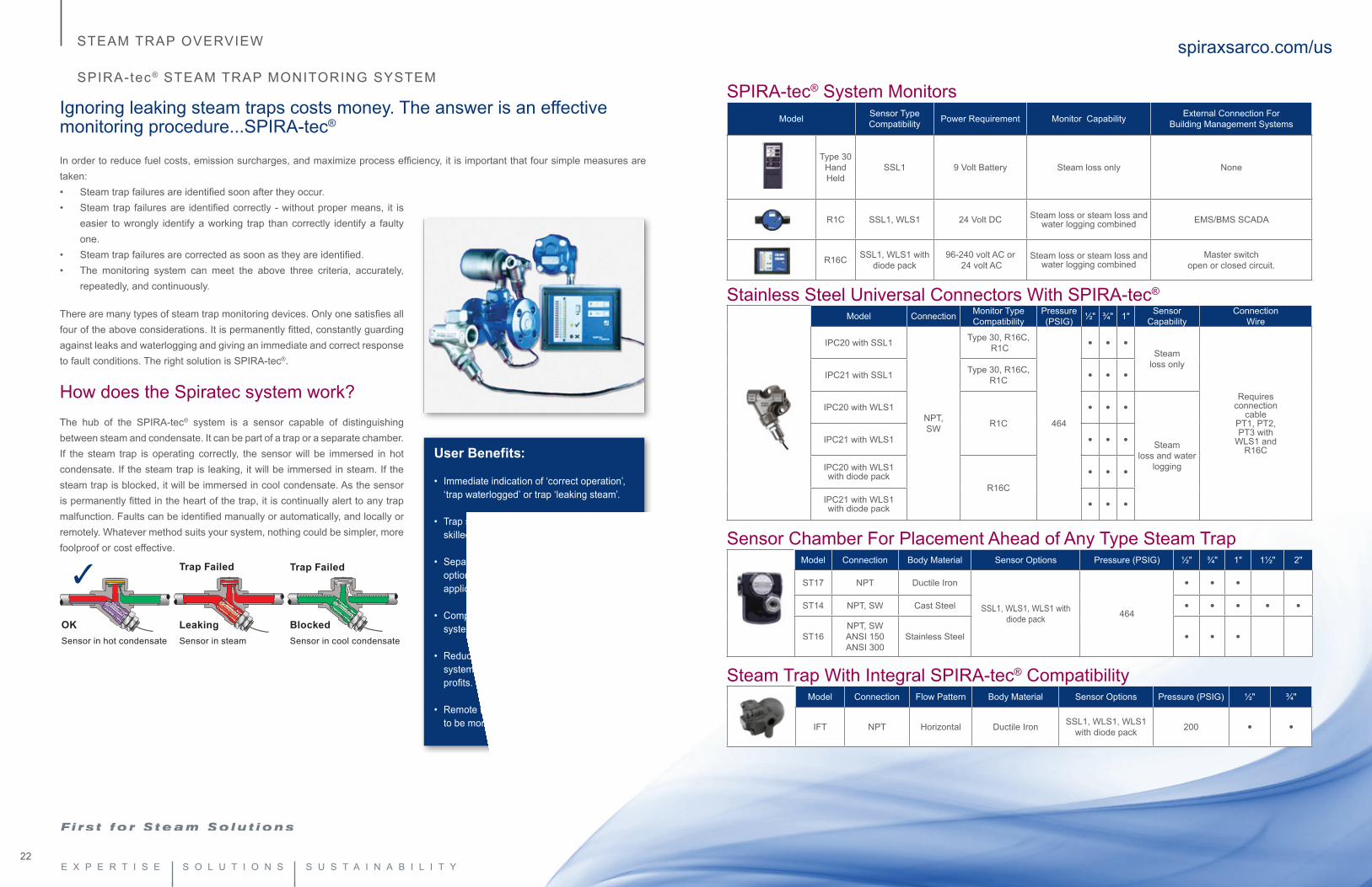
Ignoring leaking steam traps costs money. The answer is an effective monitoring procedure...SPIRA-tec®
In order to reduce fuel costs, emission surcharges, and maximize process efficiency, it is important that four simple measures are taken:• Steam trap failures are identified soon after they occur.• Steam trap failures are identified correctly - without proper means, it is
easier to wrongly identify a working trap than correctly identify a faulty one.
• Steam trap failures are corrected as soon as they are identified.• The monitoring system can meet the above three criteria, accurately,
repeatedly, and continuously.
There are many types of steam trap monitoring devices. Only one satisfies all four of the above considerations. It is permanently fitted, constantly guarding against leaks and waterlogging and giving an immediate and correct response to fault conditions. The right solution is SPIRA-tec®.
How does the Spiratec system work?The hub of the SPIRA-tec® system is a sensor capable of distinguishing between steam and condensate. It can be part of a trap or a separate chamber. If the steam trap is operating correctly, the sensor will be immersed in hot condensate. If the steam trap is leaking, it will be immersed in steam. If the steam trap is blocked, it will be immersed in cool condensate. As the sensor is permanently fitted in the heart of the trap, it is continually alert to any trap malfunction. Faults can be identified manually or automatically, and locally or remotely. Whatever method suits your system, nothing could be simpler, more foolproof or cost effective.
3
OKSensor in hot condensate
LeakingSensor in steam
BlockedSensor in cool condensate
Trap Failed Trap Failed
SPIRA-tec® System MonitorsModel Sensor Type
Compatibility Power Requirement Monitor Capability External Connection For Building Management Systems
Type 30 Hand Held
SSL1 9 Volt Battery Steam loss only None
R1C SSL1, WLS1 24 Volt DC Steam loss or steam loss and water logging combined EMS/BMS SCADA
R16C SSL1, WLS1 with diode pack
96-240 volt AC or 24 volt AC
Steam loss or steam loss and water logging combined
Master switch open or closed circuit.
Stainless Steel Universal Connectors With SPIRA-tec®
Model Connection Monitor Type Compatibility
Pressure (PSIG) ½" ¾" 1" Sensor
CapabilityConnection
Wire
IPC20 with SSL1
NPT,SW
Type 30, R16C, R1C
464
• • •Steam
loss only
Requires connection
cable PT1, PT2, PT3 with
WLS1 and R16C
IPC21 with SSL1 Type 30, R16C, R1C • • •
IPC20 with WLS1
R1C • • •
Steam loss and water
logging
IPC21 with WLS1 • • •
IPC20 with WLS1 with diode pack
R16C• • •
IPC21 with WLS1 with diode pack • • •
Sensor Chamber For Placement Ahead of Any Type Steam Trap Model Connection Body Material Sensor Options Pressure (PSIG) ½" ¾" 1" 1½" 2"
ST17 NPT Ductile Iron
SSL1, WLS1, WLS1 with diode pack 464
• • •ST14 NPT, SW Cast Steel • • • • •
ST16NPT, SWANSI 150ANSI 300
Stainless Steel • • •
Steam Trap With Integral SPIRA-tec® CompatibilityModel Connection Flow Pattern Body Material Sensor Options Pressure (PSIG) ½" ¾"
IFT NPT Horizontal Ductile Iron SSL1, WLS1, WLS1 with diode pack 200 • •
24 25
spiraxsarco.com/usSTEAM TRAP OVERVIEW
STEAM TRAP MANIFOLDS
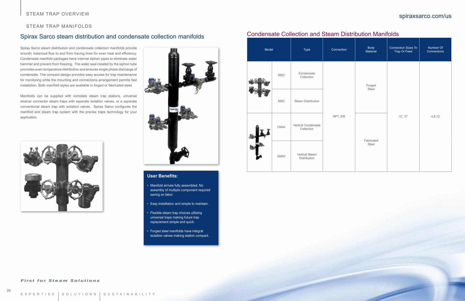
Spirax Sarco steam distribution and condensate collection manifolds
Spirax Sarco steam distribution and condensate collection manifolds provide smooth, balanced flow to and from tracing lines for even heat and efficiency. Condensate manifold packages have internal siphon pipes to eliminate water hammer and prevent from freezing. The water seal created by the siphon tube promotes even temperature distribution and ensures single phase discharge of condensate. The compact design provides easy access for trap maintenance for monitoring while the mounting and connections arrangement permits fast installation. Both manifold styles are available in forged or fabricated steel.
Manifolds can be supplied with complete steam trap stations, universal strainer connector steam traps with separate isolation valves, or a separate conventional steam trap with isolation valves. Spirax Sarco configures the manifold and steam trap system with the precise traps technology for your application.
User Benefits:
• Manifold arrives fully assembled. No assembly of multiple component required saving on labor.
• Easy installation and simple to maintain. • Flexible steam trap choices utilizing
universal traps making future trap replacement simple and quick.
• Forged steel manifolds have integral isolation valves making station compact.
Condensate Collection and Steam Distribution Manifolds
Model Type Connection BodyMaterial
Connection Sizes To Trap Or Feed
Number Of Connections
MSC Condensate Collection
NPT, SW
Forged Steel
½", ¾" 4,8,12
MSC Steam Distribution
CMAV Vertical Condensate Collection
FabricatedSteel
SMAV Vertical Steam Distribution
26 27
STEAM TRAP OVERVIEW
STEAM TRAP ACCESSORIES
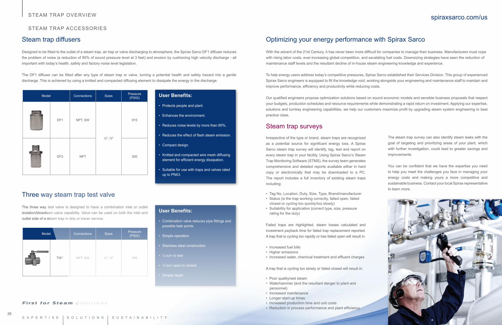
Steam trap diffusers
Designed to be fitted to the outlet of a steam trap, air trap or valve discharging to atmosphere, the Spirax Sarco DF1 diffuser reduces the problem of noise (a reduction of 80% of sound pressure level at 3 feet) and erosion by cushioning high velocity discharge - all important with today’s health, safety and factory noise level legislation.
The DF1 diffuser can be fitted after any type of steam trap or valve, turning a potential health and safety hazard into a gentle discharge. This is achieved by using a knitted and compacted diffusing element to dissipate the energy in the discharge.
User Benefits:
• Protects people and plant.
• Enhances the environment.
• Reduces noise levels by more than 80%.
• Reduces the effect of flash steam emission.
• Compact design.
• Knitted and compacted wire mesh diffusing element for efficient energy dissipation.
• Suitable for use with traps and valves rated up to PN63.
Model Connections Sizes Pressure(PSIG)
DF1 NPT, SW
½", ¾"
915
DF3 NPT 300
Three way steam trap test valve
The three way test valve is designed to have a combination inlet or outlet isolation/blowdown valve capability. Valve can be used on both the inlet and outlet side of a steam trap in drip or tracer service.
User Benefits:
• Combination valve reduces pipe fittings and possible leak points
• Simple operation
• Stainless steel construction
• ¼ turn to test
• ½ turn open to closed
• Simple repair
Model Connections Sizes Pressure(PSIG)
TWT NPT, SW ½", ¾" 300
Optimizing your energy performance with Spirax Sarco With the advent of the 21st Century, it has never been more difficult for companies to manage their business. Manufacturers must cope with rising labor costs, ever-increasing global competition, and escalating fuel costs. Downsizing strategies have seen the reduction of maintenance staff levels and the resultant decline of in-house steam engineering knowledge and experience.
To help energy users address today’s competitive pressures, Spirax Sarco established their Services Division. This group of experienced Spirax Sarco engineers is equipped to fill the knowledge void, working alongside your engineering and maintenance staff to maintain and improve performance, efficiency and productivity while reducing costs.
Our qualified engineers propose optimization solutions based on sound economic models and sensible business proposals that respect your budgets, production schedules and resource requirements while demonstrating a rapid return on investment. Applying our expertise, solutions and turnkey engineering capabilities, we help our customers maximize profit by upgrading steam system engineering to best practice class.
spiraxsarco.com/us
Steam trap surveysIrrespective of the type or brand, steam traps are recognized as a potential source for significant energy loss. A Spirax Sarco steam trap survey will identify, tag, test and report on every steam trap in your facility. Using Spirax Sarco’s Steam Trap Monitoring Software (STMS), the survey team generates comprehensive and detailed reports available either in hard copy or electronically that may be downloaded to a PC. The report includes a full inventory of existing steam traps including:
• Tag No, Location, Duty, Size, Type, Brand/manufacturer• Status (is the trap working correctly, failed open, failed
closed or cycling too quickly/too slowly)• Suitability for application (correct type, size, pressure
rating for the duty)
Failed traps are highlighted, steam losses calculated and investment payback time for failed trap replacement reported. A trap that is cycling too rapidly or has failed open will result in:
• Increased fuel bills• Higher emissions• Increased water, chemical treatment and effluent charges
A trap that is cycling too slowly or failed closed will result in:
• Poor quality/wet steam• Waterhammer (and the resultant danger to plant and
personnel)• Increased maintenance• Longer start-up times• Increased production time and unit costs• Reduction in process performance and plant efficiency
The steam trap survey can also identify steam leaks with the goal of targeting and prioritizing areas of your plant, which with further investigation, could lead to greater savings and improvements.
You can be confident that we have the expertise you need to help you meet the challenges you face in managing your energy costs and making yours a more competitive and sustainable business. Contact your local Spirax representative to learn more.

28
spiraxsarco.com/us
US Regional Offices Northeast500 W Wilson Bridge RoadSuite 135Worthington, OH 43085Phone: 614-436-8055
Mid-Atlantic4647 Saucon Creek RoadSuite 102Center Valley, PA 18034Phone: 1-800-251-7676
Southeast1150 Northpoint BlvdBlythewood, SC 29016Phone: 803-714-2125
Midwest1500 Eisenhower LaneSuite 600Lisle, IL 60532Phone: 630-493-4525
Southwest203 Georgia AvenueDeer Park, TX 77536Phone: 281-478-4002
West8141 E. Kaiser BlvdSuite 311Anaheim Hills, CA 92808Phone: 714-279-0417
2150 Miller DriveSuite HLongmont, CO 80501Phone: 1-800-356-9362
Spirax Sarco, Inc.1150 Northpoint Blvd., Blythewood, SC 29016
T 800-883-4411 or 803-714-2000F 803-714-2222
www.spiraxsarco.com/us
SPB1009 © Copyright 2012 Spirax Sarco is a registered trademark of Spirax-Sarco Limited