steanes ansett valve amplifier - dalmura ansett valve amplifier.pdf · 29/07/2012 steane’s sound...
TRANSCRIPT
29/07/2012 Steane’s Sound Systems Ansett Valve Amplifier Page 1 of 10
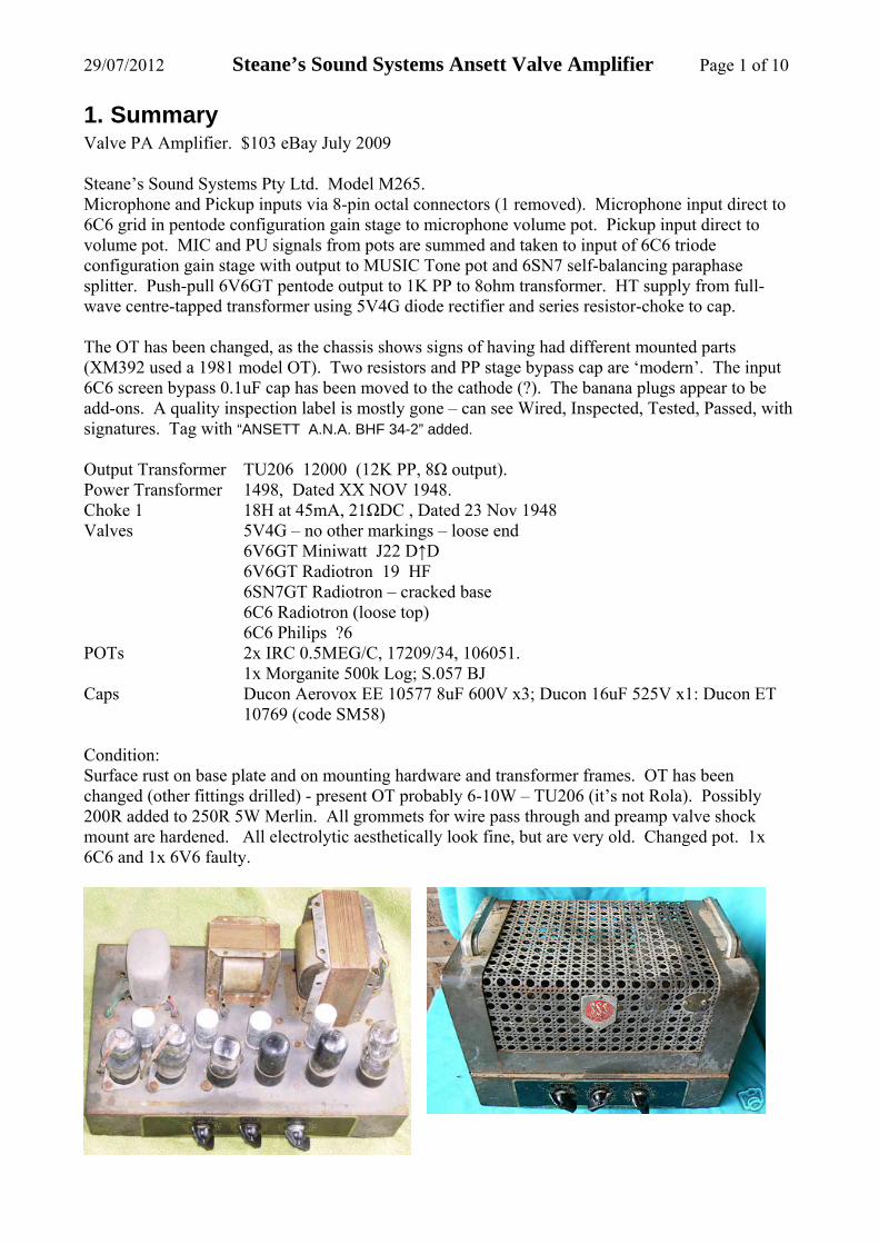
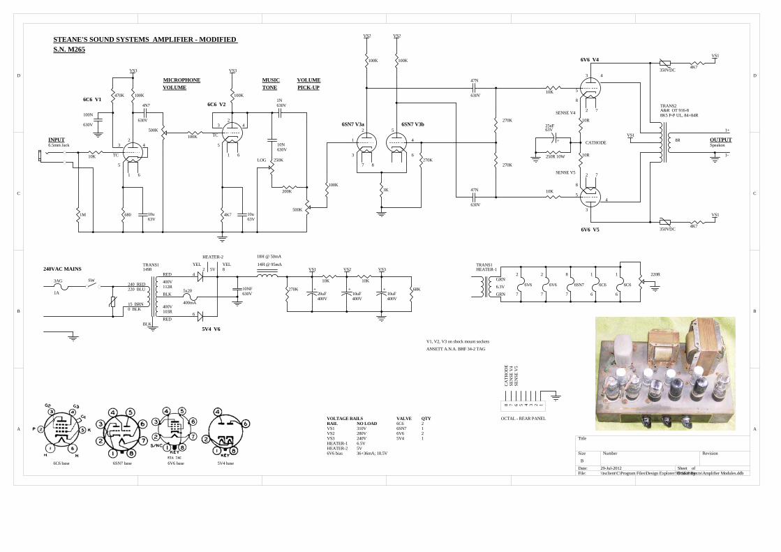
1. Summary Valve PA Amplifier. $103 eBay July 2009 Steane’s Sound Systems Pty Ltd. Model M265. Microphone and Pickup inputs via 8-pin octal connectors (1 removed). Microphone input direct to 6C6 grid in pentode configuration gain stage to microphone volume pot. Pickup input direct to volume pot. MIC and PU signals from pots are summed and taken to input of 6C6 triode configuration gain stage with output to MUSIC Tone pot and 6SN7 self-balancing paraphase splitter. Push-pull 6V6GT pentode output to 1K PP to 8ohm transformer. HT supply from full-wave centre-tapped transformer using 5V4G diode rectifier and series resistor-choke to cap. The OT has been changed, as the chassis shows signs of having had different mounted parts (XM392 used a 1981 model OT). Two resistors and PP stage bypass cap are ‘modern’. The input 6C6 screen bypass 0.1uF cap has been moved to the cathode (?). The banana plugs appear to be add-ons. A quality inspection label is mostly gone – can see Wired, Inspected, Tested, Passed, with signatures. Tag with “ANSETT A.N.A. BHF 34-2” added. Output Transformer TU206 12000 (12K PP, 8Ω output). Power Transformer 1498, Dated XX NOV 1948. Choke 1 18H at 45mA, 21ΩDC , Dated 23 Nov 1948 Valves 5V4G – no other markings – loose end 6V6GT Miniwatt J22 D↑D
6V6GT Radiotron 19 HF 6SN7GT Radiotron – cracked base 6C6 Radiotron (loose top) 6C6 Philips ?6
POTs 2x IRC 0.5MEG/C, 17209/34, 106051. 1x Morganite 500k Log; S.057 BJ Caps Ducon Aerovox EE 10577 8uF 600V x3; Ducon 16uF 525V x1: Ducon ET
10769 (code SM58) Condition: Surface rust on base plate and on mounting hardware and transformer frames. OT has been changed (other fittings drilled) - present OT probably 6-10W – TU206 (it’s not Rola). Possibly 200R added to 250R 5W Merlin. All grommets for wire pass through and preamp valve shock mount are hardened. All electrolytic aesthetically look fine, but are very old. Changed pot. 1x 6C6 and 1x 6V6 faulty.

29/07/2012 Steane’s Sound Systems Ansett Valve Amplifier Page 2 of 10
2. Modifications Megger tested power transformer and choke. Check heater voltage versus primary taps. Disconnect HT electrolytics, but leave chassis mounts in place. Remove banana sockets. Insert Speakon connector in octal base cutout. Added input socket on front panel. Added 10k grid stopper to V1. Lower grid-stopper of V2 6C6 triode to 100k. Add 100k grid-stopper to PI input. Moved Pickup pot to pre-PI. Moved tone to work with Pickup pot aka Marshal 18W tone. Replaced the power cable and faulty Tone pot.

29/07/2012 Steane’s Sound Systems Ansett Valve Amplifier Page 3 of 10
Add 10R 6V6 cathode current sense resistors, and wired sense leads to rear panel octal. Changed 6V6 grid stoppers to 10k. Add mains switch, fuse, 275VAC MOV to primary. Added 0.4A fuse to PT secondary CT. Added 4k7/350VDC MOV-R protection to OT primary. Added heater humdinger pot. Removed resistor in series with choke. Added snubber capacitor before choke. VS1 should
be about 330V – use 400V rated caps. Added neoprene washers to either side of valve base to increase compliance. Replaced in-situ OT with A&R OT916-8; 8k5 UL with 8Ω output; High fidelity range
suited to 6V6. Similar UL designs for 6V6: o Acro TO-310 OT, 8k PP, 10W hi-fi o Radiotronics June 1955 paper on 6V6 UL by Langford Smith and Chesterman.
Given the more modern ‘Philips’ style in a 1953 advert, and choke date of late 1948 – this amp is an earlier model circa 1949-50.
3. Steane’s Sound Systems The Powerhouse museum has a microphone from them, with a comment about them being in Melbourne, and then Sydney in 1940-60's. They are identified in The Argus in October 1943, and again in 1945 at 290 Exhibition St, Melbourne. There are adverts in the April 1949 Canberra times for "Stanes Sound Systems" who do PA's and sound for venues.

29/07/2012 Steane’s Sound Systems Ansett Valve Amplifier Page 4 of 10
Many adverts in Radio & Hobbies from Sept 49 to Dec 1955, with addresses for 60-80 Miller St Melb 1, and 367 Kent St Sydney 2, and many state and NZ outlets (eg. Lawrence & Hanson, and Homecrafts) focussing on sound reproduction equipment. 1953 advert shows similar casing amplifier with ratings available of 13W, 30W and 70W, and four pots – a close descendant. They had associated trading names of BRODERS PTY LTD and UNITED ELECTRONIC SERVICING PTY LTD, and became a registered company in 1931 and deregistered in 1999. They used a distinctive SSS badge on the amp I have.
1953 advert in Radio & Hobbies Graham Scott, 154 Russell St Toowoomba, QLD 4340 07 4632 4109
4. Measurements Voltage rail regulation. Rail Idle (Wurlitzer OT) Idle A&R OT 916 UL Max output VS1 305V (peaks to 370V), 850mVrms ripple 300V 297V VS2 240V VS3 195V Cathode 18.5V (27mA + 27mA) 8W 330R 18.5V (36+38mA)
250R
Heater 1 6.4V Heater 2 Sec HT 385+385V 12VAC 50Hz nominal applied to TU206 output transformer (this was replaced by Wurlitzer and the A&R OT 916-8) Winding Voltage rms Turns ratio; Impedance for 12K pri; Spec level; Notes Pri P-P: BLU to BRN 415 Sec: GRN to GRN 11.27 36.8; 8.9 Ω; Appears reasonable for 12K PP Output transformer primary DC resistance: 420Ω plate-to-plate.
1 Now Basso Project Management. Miller St is near northern section of Spencer, between Victoria and Abbotsford. Used by Briginshaw Bros in 1942. 2 Now Casablanca Media Corp. Located in central section.

29/07/2012 Steane’s Sound Systems Ansett Valve Amplifier Page 5 of 10
Power transformer primary DC resistance: 21Ω, 0-240V. Power transformer secondary DC resistance: 103+112Ω, 400-0-400V. Choke: 21Ω dc resistance; 18H at 46mADC; 14H at 95mADC. 23mVrms output noise in to 17 ohm load with pots at full level and no input (shorted at socket). 12Vrms output at start of clipping (8W) with Wurlitzer OT. Clipping is pretty symmetric, but un-driven side of PI then starts to get a scalloped dip at 10W, which is then max output level. Perhaps change PI for long-tail pair config. Tone control interacts with signal level – and loading of 6C6 is not symmetric so filter response is unbalanced. Coupling caps reduced to allow tone control to roll off bass. Perhaps change to? Large hum pickup from open 6C6, but this is reduced to negligible level with standard shell metal screen fitted. VS1 idles at 310V, and droops to 300V at full load. Screen voltage sags to 280V (effectively 260V to cathode) at full load – tweaked by reducing dropper to 2k4. Check design – may need to modify VS2, VS3. To do: guitar check; update this doc.

29/07/2012 Steane’s Sound Systems Ansett Valve Amplifier Page 6 of 10
5. Design Info
5.1 Input Gain Stage Pentode connected 6C6 gain stage. Effective signal output resistance is 270k // 500k // 1M ~ 150K. The 6C6 characteristic curves are same as for 6J7, and using 6J7 datasheet tables for resistance coupled amplifier configuration with: VS3=300V, RL=250k, Rg=500k, Rc=1k2, Rd=1.2M, gives a gain of 140. VS3=180V, RL=250k, Rg=250k, Rc=1k2, Rd=1.1M, gives a gain of 93. In-circuit measurement is RL=270K, Rd=1M, and Rg~330k (500K//1M). For lower VS3, the gain will reduce. Rc and Rd screen should be bypassed – note - bypass on screen moved ???.
Modified to triode stage with relatively low stage gain ~15, but total amp gain was too low, so reverted to pentode mode with 680R cathode, 100k anode load, and 470k screen.
5.2 2nd Gain Stage Triode connected 6C6 gain stage. Supply voltage about 250V; effective signal load resistance is 100k//470k//pot; and cathode resistor is 1K5. The plate voltage Vp axis intercept is 250V for no plate current, and the plate current Ip axis intercept is 250V / 101KΩ = 2.5mA. The gate-cathode voltage (Ec on the graph) operating point is at Vgc=1.5Kx2.5mA = 3.7V, and varies with plate current through the 1k5Ω gate-cathode resistance with the characteristic shown on the graph as a line passing through Ip=3.5mA for Vgk=-5V, and through Ip=6mA for Vgk=-10V. The intersection of the two lines is the nominal biased operating point.

29/07/2012 Steane’s Sound Systems Ansett Valve Amplifier Page 7 of 10
The input voltage swing limit is from the bias point at Vgk=-3.7V and so is fairly unsymmetrical. The triode connection tables in RCA manual suggest an Rc~4k7 to 5k6, which should achieve a better symmetry – and the gain is about 12.
5.3 Splitter stage A see-saw floating self-balancing paraphase splitter circuit using a 6SN7. Driven by 6C6 so drive impedance is different for each 6SN7 triode. Gain of 6SN7 indicates imbalance may also be substantial. Cathode bias at about 8V and 1.1mA per 6SN7 triode, and anode voltage at 160+8=170V with a 100k load and 280V HT. Output impedances of each side are fairly similar as ra of 6SN7 is quite low. Paraphase gain is ~ 1 + (1+1+1)/14 = 1.21.
100K
4K7

29/07/2012 Steane’s Sound Systems Ansett Valve Amplifier Page 8 of 10
5.4 Output Stage In this Class AB push-pull UL output stage, one 6V6 tube is pushed into conduction and the other tube is pulled into cutoff, and there is a region of overlap where both tubes conduct equivalent levels of current. The cathodes are biased with a common resistor to ground. The A&R OT 916-8 presents 8.5kΩ impedance plate-to-plate OPT for 8 ohm speaker, presents each tube with a 2.1kΩ load impedance for larger signal currents, and 4.2k loading for small signal levels. Determining a suitable bias current level is not an empirical design approach, rather it is based on the following recommendations:
Start with the lowest bias current possible (ie. most negative grid bias voltage), and based on listening tests, increase the bias current until the sound character is acceptable, but:
use the lowest possible bias current level, as this generally increases the life of the tubes, and decreases the chance of operating at excessive plate dissipation; and
keep the bias current level below 70% of the recommended design max plate dissipation (ie. <9W); and
assess the dynamic loadline to see if it moves into region of increased plate dissipation. As the output loading increases, the supply voltage VS1 sags only a few volts from 305V, due to supply regulation. Plate DC voltage will be lower than VS1 by an amount up to ~40V; ie. OPT half resistance of about 200Ω with a peak current of up to about 0.1A, and cathode bias of 20V. The screen voltage will correspondingly sag. Screen current level increases as Vg approaches 0V, possibly to over 40mA, with an additional drop across the screen stopper resistor. Screen voltage needs to sag to about 250+20=270V at start of overdrive to nominally operate in to knee. The maximum output valve bias current allowed is dependant on the maximum recommended plate dissipation of 12W for the 6V6: Ibias(max) = Pd / Vb = 12W / 300V = 40mA. Ibias(nom) = 0.7 x 12W / 300V = 28mA. Assessing the 6V6 plate curves, which show 12W constant power contour, indicates how the plate will start at quiescent level of 27mA (V1=300V).
6K

29/07/2012 Steane’s Sound Systems Ansett Valve Amplifier Page 9 of 10
The common cathode resistance is about 18V / (27mA + 27mA) = 330Ω at 1W. The nominal output power of the amplifier will then be: (Imax)2 x Rpp / 8 = 0.09 x 0.09 x 8.5k / 8 = 8.5W
12W
4K2 2K1

29/07/2012 Steane’s Sound Systems Ansett Valve Amplifier Page 10 of 10
5.5 Power Supplies The power supply is typical full-wave rectified type using double diode 5V4 and a 400-0-400VAC centre-tapped secondary. With a choke input LC filter, this gives about 340VDC at low load, reducing by about 20V for the 5V4, and 2V for the choke DC resistance, and 62V for series R, at 100mA.
12W
4K2 1K6

1 2 3 4 5 6
A
B
C
D
654321
D
C
B
A
Title
Number RevisionSize
B
Date: 4-Aug-2009 Sheet of File: C:\Program Files\Design Explorer 99 SE\Projects\Tims amps\Amplifier Modules.ddbDrawn By:
270K
6SN7 V3a
100K
1K5
630V
4N7
100K
240K
30K
6SN7 V3b
6V6 V4
6V6 V5
VS2
VS1
VS2
VS2VS3
+
525V16uF
VS1
VS1
3AG
1A 6V6220 BLU
15 BRN
2
1
5
4
3
5
8
34
5
8
6
2
7
BRN
BLU
RD
6V6
240VAC MAINS
VS1VS2VS3
NO LOADVVV
VOLTAGE RAILSRAIL
QTY
1
VALVE
0 BLK
BLK
100K
3K
470K**
30K
630V
10N
GR
500K
500K
PICK-UP
STEANE'S SOUND SYSTEMS AMPLIFIER S.N. M265
2
7
GR
6SN7
8
7
630V
4N7
0.01u
630V
MUSIC
TRANS1
BLK
WH
HEATER-1
TRANS2
625R
6SN7
500K
MICROPHONE
6.3V
4
630V0.1u 1K
2M2
500K
500K6C6 V12
TC
61
5
1M
3 4
6C6 V2
2
TC
1
5
3 4
40V25u
3
7 8
2
2 7
450R**
+
50V25uF**
7
100K 100K**
TONE
VOLUME
VOLUME
6
40V25u
630V4N7
BLK
TRANS1
RED
RED
103R
5V4 V6
18H @ 50mA+
600V
8uF
VS2
50K
VS3
50K+
600V
8uF+
600V
8uF
6V6
26C6
2
6C6
1
6
6C6
1
6
OUTPUT
LOG
INPUTOCTAL SOCKET
INPUTOCTAL SOCKET
400V112R
400V
Replacement Part **
V1, V2, V3 on shock mount sockets
HEATER-2
TU206
ANSETT A.N.A. BHF 34-2 TAG
6C6 base 6SN7 base 6V6 base 5V4 base
CLIPSAL No.430 2-pin socket
1498
14H @ 95mA
12K P-P, 420R
8R
HEATER-1 VHEATER-2 V
5V4 1
240 RED
5V
A
B
C
DD
C
B
A
Title
Number RevisionSize
B
Date: 29-Jul-2012 Sheet of File: \\tsclient\C\Program Files\Design Explorer 99 SE\Projects\Amplifier Modules.ddbDrawn By:
6SN7 V3a
100K
4K7
630V
47N
100K
270K
6SN7 V3b
6V6 V4
6V6 V5
VS2VS2
VS3VS3
+
400V20uF
VS1
6V6220 BLU
15 BRN
2
1
5
4
3
5
8
3
45
8
6
2
7
6V6
VS1VS2VS3
NO LOAD310V280V240V
VOLTAGE RAILSRAIL
QTY
1
VALVE
0 BLK
BLK
100K
3K 10K
250K
STEANE'S SOUND SYSTEMS AMPLIFIER - MODIFIED S.N. M265
2
7
6SN7
8
7
630V
47N
4N7
630V
MUSIC
TRANS1
GRN
HEATER-1
TRANS2
6SN7
500K
MICROPHONE
6.3V
4
6801M
6C6 V1
2
TC
61
5
3 4
6C6 V2
2
TC
1
5
3 4
7 8
2
2 7
250R 10W
+
63V25uF
7
270K
TONEVOLUME
6
63V10u
630V1N
VOLUME
BLK
TRANS1
RED
RED
103R
5V4 V6
VS2 VS3
+
400V10uF
6V6
26C6
2
6C6
1
6
6C6
1
6
OUTPUT
LOG
INPUT6.5mm Jack
400V112R
400V
V1, V2, V3 on shock mount sockets
HEATER-2
A&R OT 916-8
ANSETT A.N.A. BHF 34-2 TAG
6C6 base 6SN7 base 6V6 base 5V4 base
Speakon
1498
8K5 P-P UL, 84+84R
HEATER-1 6.5V5V4 1
240 RED
5V
10K
10R
10R
270K
+
400V10uF
SW
240VAC MAINS
100K
10K
500K
PICK-UP
220R
GRN
YELYEL
630V10NF
100K200K
3AG
1A 5x20
400mA
10K 10K
12345678
OCTAL - REAR PANEL
CA
THO
DE
SEN
SE V
4SE
NSE
V5
SENSE V4
SENSE V5
CATHODE
4K7
4K7
350VDC
350VDC
3
4
6
82
18H @ 50mA
14H @ 95mA
68K270K
8R
1+
1-630V10N
VS1
VS1
VS1
100K470K
63V10u
630V
100N
HEATER-2 5V6V6 bias 36+36mA; 18.5V