steel foundation solutions for projects - arcelormittal
TRANSCRIPT

Steel Foundation Solutions for ProjectsSteel Sheet Piling
General Catalogue 2012-2

Cover:New breakwater and LNG Terminal | Port of Swinoujscie | PolandThe port of Swinoujscie, Poland, situated directly on the sea, is among the largest seaports in the Baltic Sea region. The project includes the construction of LNG (Liquid Natural Gas) terminals, and new facilities for ships with a draught of 13.5 m and length up to 300 m. The LNG terminal, a facility to off-take and re-gasify liquefied natural gas, is designed as an external port situated next to the new larger and longer eastern breakwater. The terminal will receive vessels of about 70 000 DWT (dead weight tonnes). The new breakwater is around 3 km long and will turn the external port into a shelter for any vessel at sea near the port. For the breakwater, 13 600 tonnes of steel pipes up to 24.6 m long, and 3 250 tonnes of sheet piles were delivered to the job-site in less than five months. The loading quay wall required approximately 1 100 tonnes of an HZM/AZ combi-wall system, with the HZM king piles up to 26.8 m long. In total around 22 690 tonnes of steel foundation elements were delivered to this project that should be inaugurated at the end of 2012.More info: http://www.arcelormittal.com/sheetpiling/projects/display/title/Swinoujscie

Steel Foundation Solutions for ProjectsSteel Sheet Piling
General Catalogue 2012-2
4
Printed on FSC paper.The FSC label certifies that the wood comes from forests or plantations that are managed in a responsible and sustainable way (the FSC principles promote the social, economical, environmental and cultural needs of today’s and the next generations). www.fsc.org
Disclaimer
The data and commentary contained within this steel sheet piling document is for general information purposes only. It is provided without warranty of any kind. ArcelorMittal Commercial RPS S.à r.l. shall not be held responsible for any errors, omissions or misuse of any of the enclosed information and hereby disclaims any and all liability resulting from the ability or inability to use the information contained within. Anyone making use of this material does so at his/her own risk. In no event will ArcelorMittal Commercial RPS S.à r.l. be held liable for any damages including lost profits, lost savings or other incidental or consequential damages arising from use of or inability to use the information contained within. Our sheet pile range is liable to change without notice.
Edition 10.2012 - Printed in Luxembourg
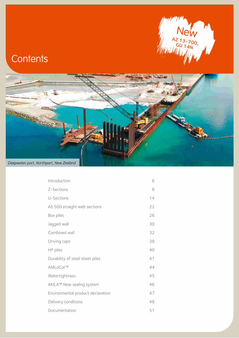
Deepwater port, Northport, New Zealand
Introduction 6
Z-Sections 8
U-Sections 14
AS 500 straight web sections 22
Box piles 26
Jagged wall 30
Combined wall 32
Driving caps 38
HP piles 40
Durability of steel sheet piles 41
AMLoCor™ 44
Watertightness 45
AKILA™ New sealing system 46
Environmental product declaration 47
Delivery conditions 48
Documentation 51
Contents
NewAZ 13-700, GU 14N
ArcelorMittal is the world’s largest producer of hot-rolled steel sheet piles. LCE – Sheet Piling is in charge of the sales, marketing and promotion of hot rolled steel sheet piles, cold formed sheet piles, bearing piles and foundation solutions produced by following ArcelorMittal mills:- hot rolled sheet piles: Belval and Differdange in
Luxembourg, Dabrowa in Poland,- cold formed sheet piles: ‘Palfroid’ in Messempré, France,- steel tubes (for foundations): Dintelmond,
The Netherlands.
Additionally, LCE - Sheet Piling can supply any accessory required for a complete foundation solution package, including anchorage material, walers, fabricated piles, coated piles, driving caps, etc.
ArcelorMittal Belval (formerly known as ProfilArbed) is the world’s largest rolling mill of hot rolled steel sheet piles and has been playing a leading role in the development of piling technology for over 100 years. The first steel sheet piles were rolled in 1911 and 1912: the ‘Ransome’ and ‘Terre Rouge’ piles. Since then the production program of ArcelorMittal’s mill in Belval has undergone constant improvement and development to include U-piles with widths of up to 750 mm (AU) and Z-piles up to 700 / 770 mm wide (AZ-700, AZ-770).
ArcelorMittal Differdange produces the biggest HZM sections to form the most competitive high modulus combined wall system.
Following the merger with Mittal Steel in 2006, the U-type piles produced by ArcelorMittal’s mill in Dabrowa, Poland (formerly Huta Katowice), are also marketed through LCE – Sheet Piling.
ArcelorMittal’s piling series are especially suitable for building reliable structures rapidly and cost-effectively. They are characterised by excellent section modulus to weight ratios and high moments of inertia. Steel sheet piles are used worldwide for the construction of quay walls and breakwaters in harbours, locks, and for bank reinforcement on rivers and canals. Other applications are temporary cofferdams in land and in water, permanent bridge abutments, retaining walls for underpasses or underground car parks, impervious containment walls, etc.
The Technical Department offers comprehensive services throughout the world with customised support to all the parties involved in the design, specification and installation of sheet and bearing piles, e.g. consulting engineers, architects, regional authorities, contractors, academics and their students.
Sheet pile catalogues, 1910s
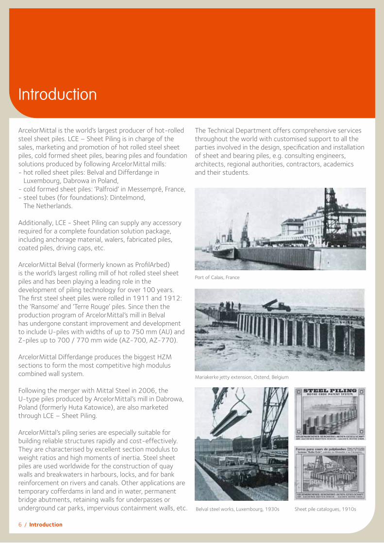
Mariakerke jetty extension, Ostend, Belgium
6 / Introduction
Introduction
Belval steel works, Luxembourg, 1930s
Port of Calais, France

Introduction / 7
In-house design team
Services provided free of charge by ArcelorMittal’s in-house design and support teams:- preliminary designs of complete solutions including
anchorage systems and lifetime calculations,- project optimizations offered to end-users to provide
the most competitive piling package,- elaboration of detailed project layouts and supply chains,- assistance and recommendations on pile installation
methods and driving equipment,- promotion of “green sheet piles”, including Life Cycle
Assessment.
Please note that the legal responsibility for the fi nal structure remains with the owner.
Feasibility studies
Sheet pile installation drawings
Preliminary designs
Solutions for execution details
HZ 1080M B
RZD 16
RZU 16
U 400
AZ 26
Anchor Ø 75 / 179
Plate 450x200x40Plate 500x180x30Bolt Ø 103 / L = 260L = 260L
Ø 150
Complete solutions including sheet pile walls, anchors, corner layouts and special piles.

8 / Z-Sections
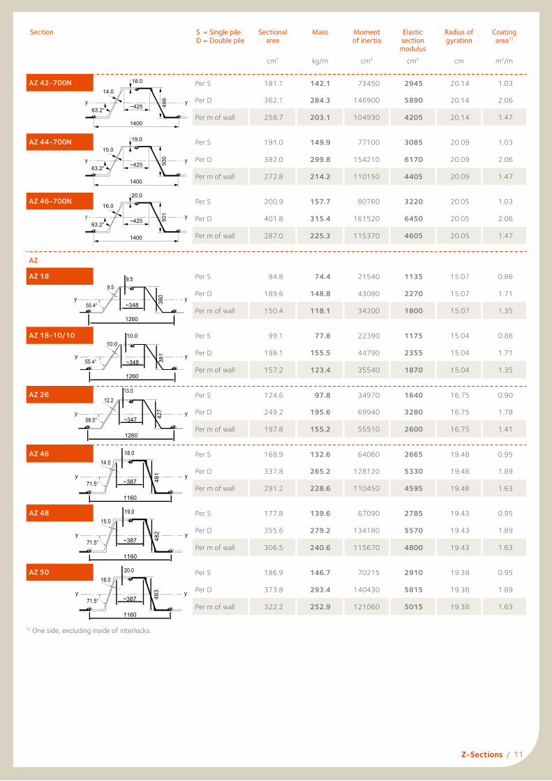
Z-SectionsThe essential characteristics of Z-sections are the continuous form of the web and the location of the interlock symmetrically on each side of the neutral axis. Both aspects have a positive influence on the section modulus. The AZ series, a section with extraordinary characteristics and the proven qualities of the Larssen interlock, has the following advantages:– Extremely competitive section-modulus-to-mass ratio.– Increased inertia for reduced deflection.– Large width, resulting in good installation performance.– Good corrosion resistance, the steel being thickest at the critical corrosion points.
Section Width
Height
Thickness
Sectional area
Mass
Moment of
inertia
Elastic section
modulus
Static moment
Plastic section
modulus
Class1)
b
mm
h
mm
t
mm
s
mm cm2/msingle pile
kg/mwall
kg/m2 cm4/m cm3/m cm3/m cm3/m S 24
0 GP
S 27
0 GP
S 32
0 GP
S 35
5 GP
S 39
0 GP
S 43
0 GP
S 46
0 AP
AZ-700 and AZ-770
AZ 12-770 770 344 8.5 8.5 120 72.6 94 21430 1245 740 1480 2 2 3 3 3 3 3
AZ 13-770 770 344 9.0 9.0 126 76.1 99 22360 1300 775 1546 2 2 3 3 3 3 3
AZ 14-770 770 345 9.5 9.5 132 79.5 103 23300 1355 805 1611 2 2 2 2 3 3 3
AZ 14-770-10/10 770 345 10.0 10.0 137 82.9 108 24240 1405 840 1677 2 2 2 2 2 3 3
AZ 12-700 700 314 8.5 8.5 123 67.7 97 18880 1205 710 1415 2 2 3 3 3 3 3
AZ 13-700 700 315 9.5 9.5 135 74.0 106 20540 1305 770 1540 2 2 2 3 3 3 3
AZ 13-700-10/10 700 316 10.0 10.0 140 77.2 110 21370 1355 800 1600 2 2 2 2 3 3 3
AZ 14-700 700 316 10.5 10.5 146 80.3 115 22190 1405 835 1665 2 2 2 2 2 3 3
AZ 17-700 700 420 8.5 8.5 133 73.1 104 36230 1730 1015 2027 2 2 3 3 3 3 3
AZ 18-700 700 420 9.0 9.0 139 76.5 109 37800 1800 1060 2116 2 2 3 3 3 3 3
AZ 19-700 700 421 9.5 9.5 146 80.0 114 39380 1870 1105 2206 2 2 2 3 3 3 3
AZ 20-700 700 421 10.0 10.0 152 83.5 119 40960 1945 1150 2296 2 2 2 2 2 3 3
AZ 24-700 700 459 11.2 11.2 174 95.7 137 55820 2430 1435 2867 2 2 2 2 2 2 3
AZ 26-700 700 460 12.2 12.2 187 102.9 147 59720 2600 1535 3070 2 2 2 2 2 2 2
AZ 28-700 700 461 13.2 13.2 200 110.0 157 63620 2760 1635 3273 2 2 2 2 2 2 2
AZ 36-700N 700 499 15.0 11.2 216 118.6 169 89610 3590 2055 4110 2 2 2 2 2 2 2
AZ 38-700N 700 500 16.0 12.2 230 126.4 181 94840 3795 2180 4360 2 2 2 2 2 2 2
AZ 40-700N 700 501 17.0 13.2 244 134.2 192 100080 3995 2305 4605 2 2 2 2 2 2 2
AZ 42-700N 700 499 18.0 14.0 259 142.1 203 104930 4205 2425 4855 2 2 2 2 2 2 2
AZ 44-700N 700 500 19.0 15.0 273 149.9 214 110150 4405 2550 5105 2 2 2 2 2 2 2
AZ 46-700N 700 501 20.0 16.0 287 157.7 225 115370 4605 2675 5350 2 2 2 2 2 2 2
AZ
AZ 182) 630 380 9.5 9.5 150 74.4 118 34200 1800 1050 2104 2 2 2 3 3 3 3
AZ 18-10/10 630 381 10.0 10.0 157 77.8 123 35540 1870 1095 2189 2 2 2 2 3 3 3
AZ 262) 630 427 13.0 12.2 198 97.8 155 55510 2600 1530 3059 2 2 2 2 2 2 2
AZ 46 580 481 18.0 14.0 291 132.6 229 110450 4595 2650 5295 2 2 2 2 2 2 2
AZ 48 580 482 19.0 15.0 307 139.6 241 115670 4800 2775 5553 2 2 2 2 2 2 2
AZ 50 580 483 20.0 16.0 322 146.7 253 121060 5015 2910 5816 2 2 2 2 2 2 2
1) Classification according to EN 1993-5. Class 1 is obtained by verification of the rotation capacity for a class-2 cross-section. A set of tables with all the data required for design in accordance with EN 1993-5 is available from our Technical Department. Steel grade S 460 AP following specifications of the mill is available on request.
2) AZ sections can be rolled-up or down by 0.5 mm and 1.0 mm on request.
NewAZ 13-700
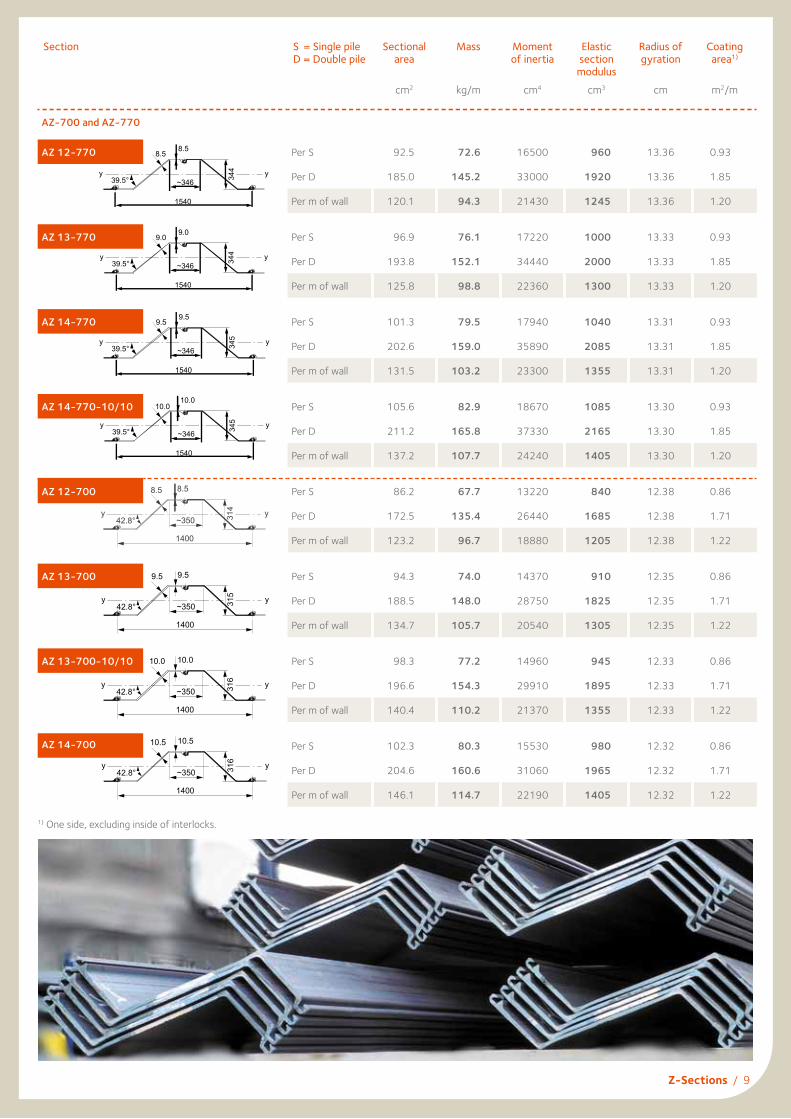
Section S = Single pile D = Double pile
Sectional area
cm2
Mass
kg/m
Moment of inertia
cm4
Elastic section
moduluscm3
Radius of gyration
cm
Coating area1)
m2/m
AZ-700 and AZ-770
AZ 12-770 Per S 92.5 72.6 16500 960 13.36 0.93
Per D 185.0 145.2 33000 1920 13.36 1.85
Per m of wall 120.1 94.3 21430 1245 13.36 1.20
AZ 13-770 Per S 96.9 76.1 17220 1000 13.33 0.93
Per D 193.8 152.1 34440 2000 13.33 1.85
Per m of wall 125.8 98.8 22360 1300 13.33 1.20
AZ 14-770 Per S 101.3 79.5 17940 1040 13.31 0.93
Per D 202.6 159.0 35890 2085 13.31 1.85
Per m of wall 131.5 103.2 23300 1355 13.31 1.20
AZ 14-770-10/10 Per S 105.6 82.9 18670 1085 13.30 0.93
Per D 211.2 165.8 37330 2165 13.30 1.85
Per m of wall 137.2 107.7 24240 1405 13.30 1.20
AZ 12-700 Per S 86.2 67.7 13220 840 12.38 0.86
Per D 172.5 135.4 26440 1685 12.38 1.71
Per m of wall 123.2 96.7 18880 1205 12.38 1.22
AZ 13-700 Per S 94.3 74.0 14370 910 12.35 0.86
Per D 188.5 148.0 28750 1825 12.35 1.71
Per m of wall 134.7 105.7 20540 1305 12.35 1.22
AZ 13-700-10/10 Per S 98.3 77.2 14960 945 12.33 0.86
Per D 196.6 154.3 29910 1895 12.33 1.71
Per m of wall 140.4 110.2 21370 1355 12.33 1.22
AZ 14-700 Per S 102.3 80.3 15530 980 12.32 0.86
Per D 204.6 160.6 31060 1965 12.32 1.71
Per m of wall 146.1 114.7 22190 1405 12.32 1.22
Z-Sections / 9
1400
~350y y
8.58.5
314
42.8°
1400
~350y y
10.010.0
316
42.8°
1400
~350y y
9.59.5
315
42.8°
AZ 14 - 770
1540
~346yy
9.59.5
54339.5°AZ 14 - 770 - 10/10
1540
~346yy
10.010.0
345
39.5°
AZ 12 - 770
1540
~346yy
8.58.5
44339.5°AZ 13 - 770
1540
~346yy
9.09.0
44339.5°
1) One side, excluding inside of interlocks.
1400
~350y y
10.510.5
316
42.8°

Section S = Single pile D = Double pile
Sectional area
cm2
Mass
kg/m
Moment of inertia
cm4
Elastic section
moduluscm3
Radius of gyration
cm
Coating area1)
m2/m
AZ 17-700 Per S 93.1 73.1 25360 1210 16.50 0.93
Per D 186.2 146.2 50720 2420 16.50 1.86
Per m of wall 133.0 104.4 36230 1730 16.50 1.33
AZ 18-700 Per S 97.5 76.5 26460 1260 16.47 0.93
Per D 194.9 153.0 52920 2520 16.47 1.86
Per m of wall 139.2 109.3 37800 1800 16.47 1.33
AZ 19-700 Per S 101.9 80.0 27560 1310 16.44 0.93
Per D 203.8 160.0 55130 2620 16.44 1.86
Per m of wall 145.6 114.3 39380 1870 16.44 1.33
AZ 20-700 Per S 106.4 83.5 28670 1360 16.42 0.93
Per D 212.8 167.0 57340 2725 16.42 1.86
Per m of wall 152.0 119.3 40960 1945 16.42 1.33
AZ 24-700 Per S 121.9 95.7 39080 1700 17.90 0.97
Per D 243.8 191.4 78150 3405 17.90 1.93
Per m of wall 174.1 136.7 55820 2430 17.90 1.38
AZ 26-700 Per S 131.0 102.9 41800 1815 17.86 0.97
Per D 262.1 205.7 83610 3635 17.86 1.93
Per m of wall 187.2 146.9 59720 2600 17.86 1.38
AZ 28-700 Per S 140.2 110.0 44530 1930 17.83 0.97
Per D 280.3 220.1 89070 3865 17.83 1.93
Per m of wall 200.2 157.2 63620 2760 17.83 1.38
AZ 36-700N Per S 151.1 118.6 62730 2510 20.37 1.03
Per D 302.2 237.3 125450 5030 20.37 2.05
Per m of wall 215.9 169.5 89610 3590 20.37 1.47
AZ 38-700N Per S 161.0 126.4 66390 2655 20.31 1.03
Per D 322.0 252.8 132780 5310 20.31 2.05
Per m of wall 230.0 180.6 94840 3795 20.31 1.47
AZ 40-700N Per S 170.9 134.2 70060 2795 20.25 1.03
Per D 341.9 268.4 140110 5595 20.25 2.05
Per m of wall 244.2 191.7 100080 3995 20.25 1.47
AZ 38-700N
1400
~425yy
16.0
00563.2°
12.2
AZ 40-700N
1400
~425yy
17.0
10563.2°
13.2
AZ 36-700N
1400
~425yy
15.0
99463.2°
11.2
1) One side, excluding inside of interlocks.
10 / Z-Sections
1400
yy
12.212.2
460
55.2° ~361
1400
yy
13.213.2
461
55.2° ~361
1400
yy
11.211.2
459
55.2° ~361
AZ 17 - 700
1400
~346yy
8.58.5
02451.2°
AZ 19 - 700
1400
~346yy
9.59.5
12451.2°
AZ 18 - 700
1400
~346yy
9.09.0
02451.2°
Section S = Single pile D = Double pile
Sectional area
cm2
Mass
kg/m
Moment of inertia
cm4
Elastic section
moduluscm3
Radius of gyration
cm
Coating area1)
m2/m
AZ 42-700N Per S 181.1 142.1 73450 2945 20.14 1.03
Per D 362.1 284.3 146900 5890 20.14 2.06
Per m of wall 258.7 203.1 104930 4205 20.14 1.47
AZ 44-700N Per S 191.0 149.9 77100 3085 20.09 1.03
Per D 382.0 299.8 154210 6170 20.09 2.06
Per m of wall 272.8 214.2 110150 4405 20.09 1.47
AZ 46-700N Per S 200.9 157.7 80760 3220 20.05 1.03
Per D 401.8 315.4 161520 6450 20.05 2.06
Per m of wall 287.0 225.3 115370 4605 20.05 1.47
AZ
AZ 18 Per S 94.8 74.4 21540 1135 15.07 0.86
Per D 189.6 148.8 43080 2270 15.07 1.71
Per m of wall 150.4 118.1 34200 1800 15.07 1.35
AZ 18-10/10 Per S 99.1 77.8 22390 1175 15.04 0.86
Per D 198.1 155.5 44790 2355 15.04 1.71
Per m of wall 157.2 123.4 35540 1870 15.04 1.35
AZ 26 Per S 124.6 97.8 34970 1640 16.75 0.90
Per D 249.2 195.6 69940 3280 16.75 1.78
Per m of wall 197.8 155.2 55510 2600 16.75 1.41
AZ 46 Per S 168.9 132.6 64060 2665 19.48 0.95
Per D 337.8 265.2 128120 5330 19.48 1.89
Per m of wall 291.2 228.6 110450 4595 19.48 1.63
AZ 48 Per S 177.8 139.6 67090 2785 19.43 0.95
Per D 355.6 279.2 134180 5570 19.43 1.89
Per m of wall 306.5 240.6 115670 4800 19.43 1.63
AZ 50 Per S 186.9 146.7 70215 2910 19.38 0.95
Per D 373.8 293.4 140430 5815 19.38 1.89
Per m of wall 322.2 252.9 121060 5015 19.38 1.63
AZ 18 - 10/10
1260
~348yy
10.010.0
381
55.4°
bb
h
ts
1260
~348yy
9.59.5
08355.4°
bb
h
AZ 18 ts
1260
~347yy
13.012.2
72458.5°
bb
h
AZ 26 t
s
1400
~425y y
18.0
499
63.2°
14.0
1400
~425y y
19.0
500
63.2°
15.0
1400
~425y y
20.0
501
63.2°
16.0
1) One side, excluding inside of interlocks.
AZ 46
1160
~387yy
18.014.0
71.5°
bb
h
t
s
481AZ 50
1160
~387yy
20.016.0
71.5°
bb
h
t
s
483
AZ 48
1160
~387yy
19.015.0
71.5°
bb
h
t
s
482
Z-Sections / 11
12 / Z-Sections
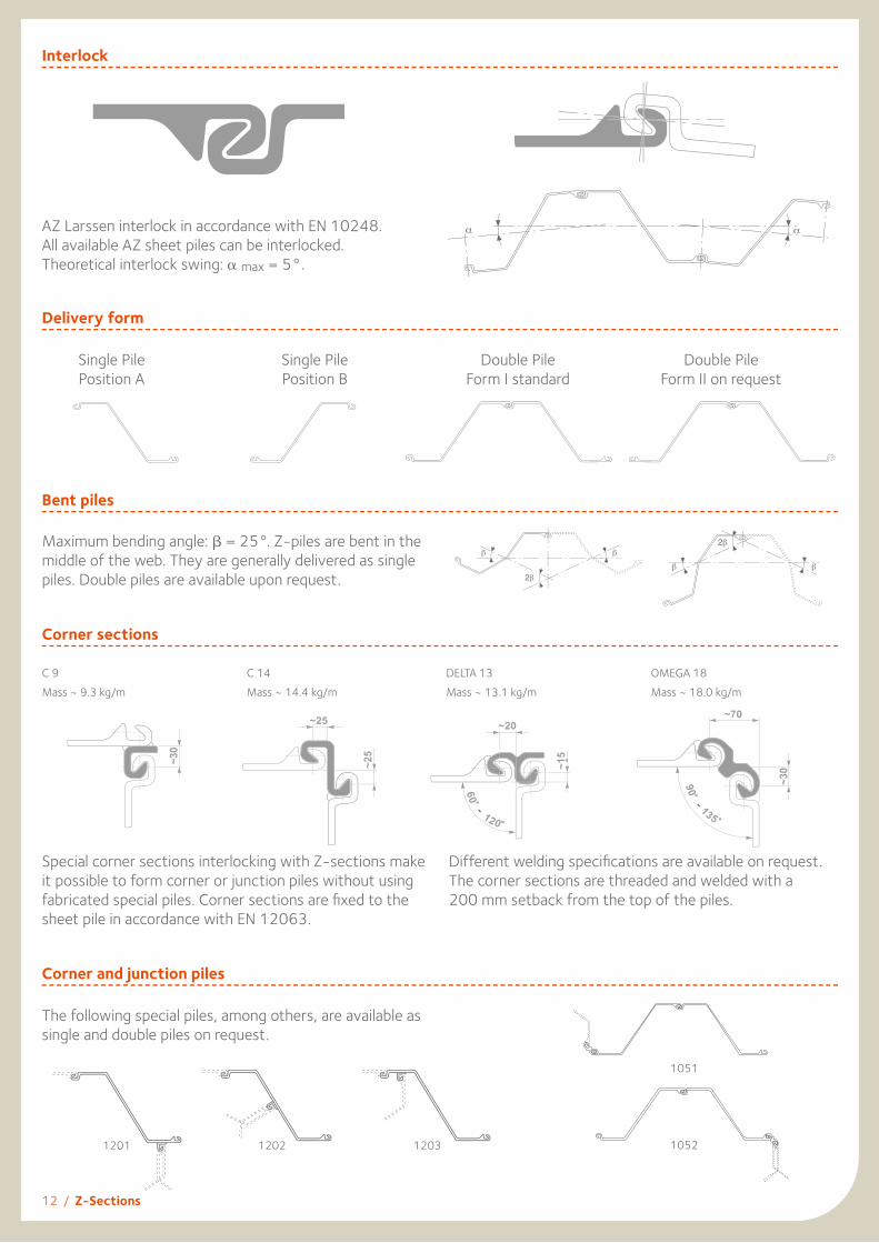
Interlock
AZ Larssen interlock in accordance with EN 10248. All available AZ sheet piles can be interlocked. Theoretical interlock swing: α max = 5°.
Bent piles
Maximum bending angle: β = 25°. Z-piles are bent in the middle of the web. They are generally delivered as single piles. Double piles are available upon request.
Corner sections
C 9Mass ~ 9.3 kg/m
C 14Mass ~ 14.4 kg/m
DELTA 13Mass ~ 13.1 kg/m
OMEGA 18Mass ~ 18.0 kg/m
Special corner sections interlocking with Z-sections make it possible to form corner or junction piles without using fabricated special piles. Corner sections are fi xed to the sheet pile in accordance with EN 12063.
Different welding specifi cations are available on request. The corner sections are threaded and welded with a200 mm setback from the top of the piles.
Single PilePosition A
Single PilePosition B
Double PileForm I standard
Double PileForm II on request
Delivery form
α α
Corner and junction piles
The following special piles, among others, are available as single and double piles on request.
1201 1202 1203
1051
1052
Z-Sections / 13
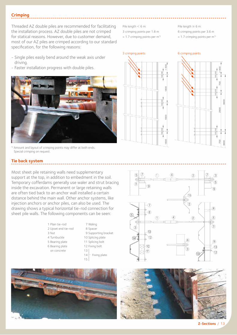
Threaded AZ double piles are recommended for facilitating the installation process. AZ double piles are not crimped for statical reasons. However, due to customer demand, most of our AZ piles are crimped according to our standard specifi cation, for the following reasons:
- Single piles easily bend around the weak axis under driving.
- Faster installation progress with double piles.
Crimping
Pile length < 6 m:3 crimping points per 1.8 m= 1.7 crimping points per m1)
Pile length ≥ 6 m:6 crimping points per 3.6 m= 1.7 crimping points per m1)
Most sheet pile retaining walls need supplementarysupport at the top, in addition to embedment in the soil. Temporary cofferdams generally use waler and strut bracing inside the excavation. Permanent or large retaining wallsare often tied back to an anchor wall installed a certain distance behind the main wall. Other anchor systems, like injection anchors or anchor piles, can also be used. The drawing shows a typical horizontal tie-rod connection for sheet pile walls. The following components can be seen:
1 Plain tie-rod 7 Waling 2 Upset end tie-rod 8 Spacer 3 Nut 9 Supporting bracket 4 Turnbuckle 10 Splicing plate 5 Bearing plate 11 Splicing bolt 6 Bearing plate 12 Fixing bolt on concrete 13 14 Fixing plate 15
Tie back system
175
39
4 2 7 3
5
9
8
5
3
2
9
13
12
15
3
3
6
11
10
12
133
8
7
1 4
3 crimping points 6 crimping points
14 Fixing plate 14 Fixing plate
1) Amount and layout of crimping points may differ at both ends. Special crimping on request.
< 5
00
1800
100 1
00
1800
100
100
1800
100
100
< 50
0 70
0
100 1
00
2900
100
100
700
100
100
3600
36
00
14 / U-Sections
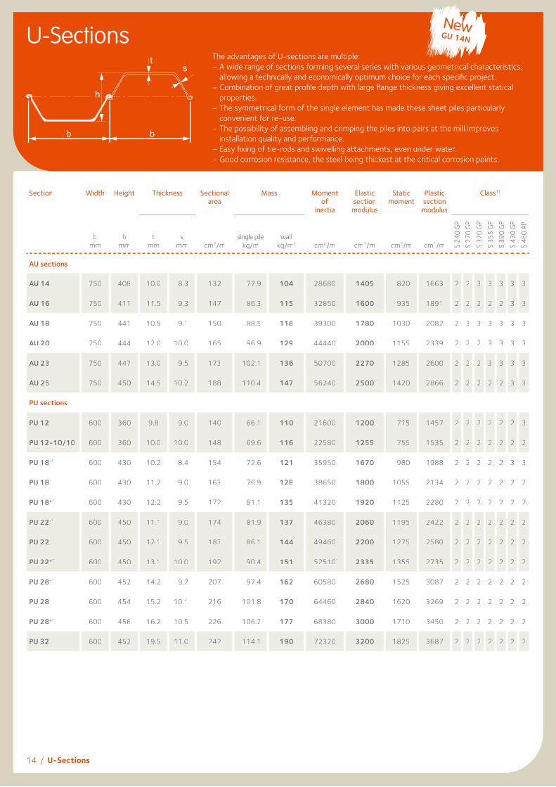
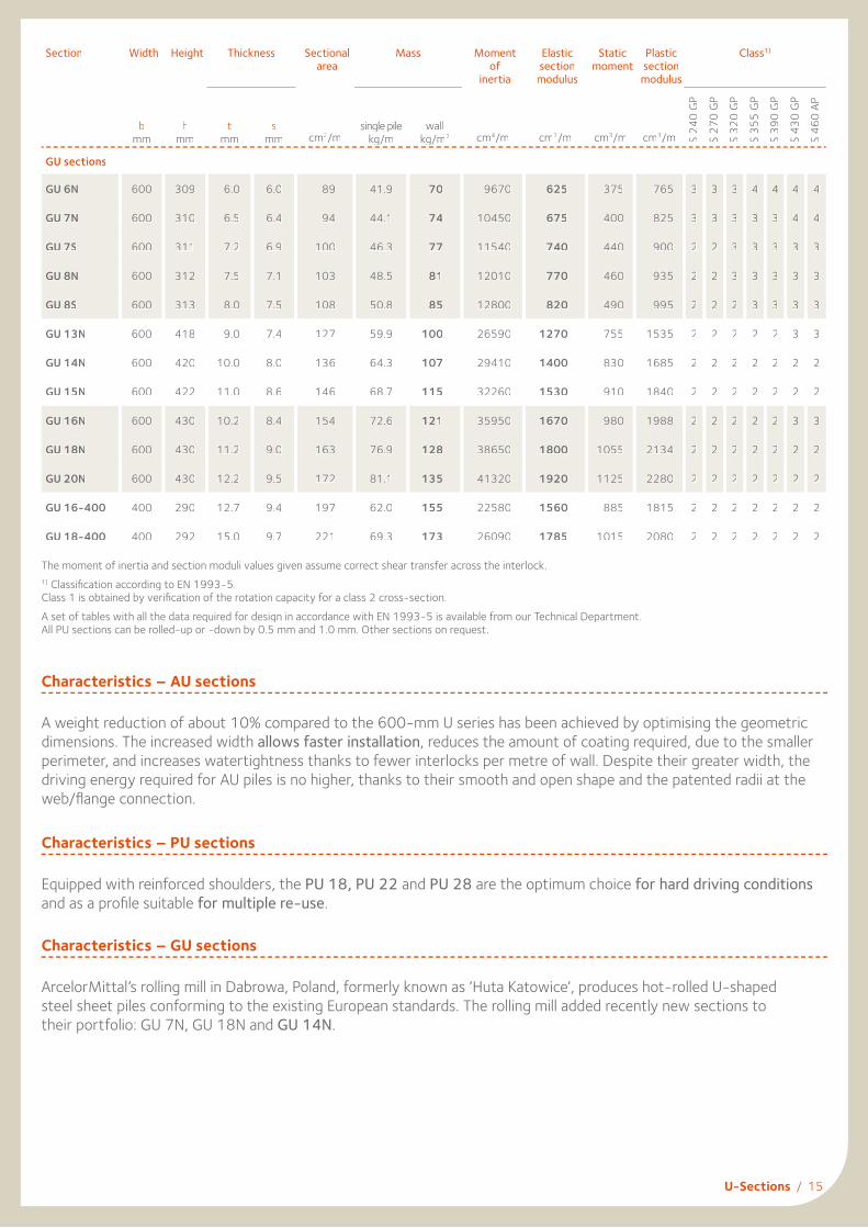
U-SectionsThe advantages of U-sections are multiple:– A wide range of sections forming several series with various geometrical characteristics,
allowing a technically and economically optimum choice for each specifi c project.– Combination of great profi le depth with large fl ange thickness giving excellent statical
properties.– The symmetrical form of the single element has made these sheet piles particularly
convenient for re-use.– The possibility of assembling and crimping the piles into pairs at the mill improves
installation quality and performance.– Easy fi xing of tie-rods and swivelling attachments, even under water.– Good corrosion resistance, the steel being thickest at the critical corrosion points.
Section Width Height Thickness Sectionalarea
Mass Momentof
inertia
Elasticsection
modulus
Staticmoment
Plasticsection
modulus
Class1)
bmm
hmm
tmm
smm cm2/m
single pilekg/m
wallkg/m2 cm4/m cm3/m cm3/m cm3/m S
240
GPS
270
GPS
320
GPS
355
GPS
390
GPS
430
GPS
460
AP
AU sections
AU 14 750 408 10.0 8.3 132 77.9 104 28680 1405 820 1663 2 2 3 3 3 3 3
AU 16 750 411 11.5 9.3 147 86.3 115 32850 1600 935 1891 2 2 2 2 2 3 3
AU 18 750 441 10.5 9.1 150 88.5 118 39300 1780 1030 2082 2 3 3 3 3 3 3
AU 20 750 444 12.0 10.0 165 96.9 129 44440 2000 1155 2339 2 2 2 3 3 3 3
AU 23 750 447 13.0 9.5 173 102.1 136 50700 2270 1285 2600 2 2 2 3 3 3 3
AU 25 750 450 14.5 10.2 188 110.4 147 56240 2500 1420 2866 2 2 2 2 2 3 3
PU sections
PU 12 600 360 9.8 9.0 140 66.1 110 21600 1200 715 1457 2 2 2 2 2 2 3
PU 12-10/10 600 360 10.0 10.0 148 69.6 116 22580 1255 755 1535 2 2 2 2 2 2 2
PU 18-1 600 430 10.2 8.4 154 72.6 121 35950 1670 980 1988 2 2 2 2 2 3 3
PU 18 600 430 11.2 9.0 163 76.9 128 38650 1800 1055 2134 2 2 2 2 2 2 2
PU 18+1 600 430 12.2 9.5 172 81.1 135 41320 1920 1125 2280 2 2 2 2 2 2 2
PU 22-1 600 450 11.1 9.0 174 81.9 137 46380 2060 1195 2422 2 2 2 2 2 2 2
PU 22 600 450 12.1 9.5 183 86.1 144 49460 2200 1275 2580 2 2 2 2 2 2 2
PU 22+1 600 450 13.1 10.0 192 90.4 151 52510 2335 1355 2735 2 2 2 2 2 2 2
PU 28-1 600 452 14.2 9.7 207 97.4 162 60580 2680 1525 3087 2 2 2 2 2 2 2
PU 28 600 454 15.2 10.1 216 101.8 170 64460 2840 1620 3269 2 2 2 2 2 2 2
PU 28+1 600 456 16.2 10.5 226 106.2 177 68380 3000 1710 3450 2 2 2 2 2 2 2
PU 32 600 452 19.5 11.0 242 114.1 190 72320 3200 1825 3687 2 2 2 2 2 2 2
bb
h
ts
NewGU 14N
U-Sections / 15
Section Width Height Thickness Sectionalarea
Mass Momentof
inertia
Elasticsection
modulus
Staticmoment
Plasticsection
modulus
Class1)
bmm
hmm
tmm
smm cm2/m
single pilekg/m
wallkg/m2 cm4/m cm3/m cm3/m cm3/m S
240
GP
S 27
0 GP
S 32
0 GP
S 35
5 GP
S 39
0 GP
S 43
0 GP
S 46
0 AP
GU sections
GU 6N 600 309 6.0 6.0 89 41.9 70 9670 625 375 765 3 3 3 4 4 4 4
GU 7N 600 310 6.5 6.4 94 44.1 74 10450 675 400 825 3 3 3 3 3 4 4
GU 7S 600 311 7.2 6.9 100 46.3 77 11540 740 440 900 2 2 3 3 3 3 3
GU 8N 600 312 7.5 7.1 103 48.5 81 12010 770 460 935 2 2 3 3 3 3 3
GU 8S 600 313 8.0 7.5 108 50.8 85 12800 820 490 995 2 2 2 3 3 3 3
GU 13N 600 418 9.0 7.4 127 59.9 100 26590 1270 755 1535 2 2 2 2 2 3 3
GU 14N 600 420 10.0 8.0 136 64.3 107 29410 1400 830 1685 2 2 2 2 2 2 2
GU 15N 600 422 11.0 8.6 146 68.7 115 32260 1530 910 1840 2 2 2 2 2 2 2
GU 16N 600 430 10.2 8.4 154 72.6 121 35950 1670 980 1988 2 2 2 2 2 3 3
GU 18N 600 430 11.2 9.0 163 76.9 128 38650 1800 1055 2134 2 2 2 2 2 2 2
GU 20N 600 430 12.2 9.5 172 81.1 135 41320 1920 1125 2280 2 2 2 2 2 2 2
GU 16-400 400 290 12.7 9.4 197 62.0 155 22580 1560 885 1815 2 2 2 2 2 2 2
GU 18-400 400 292 15.0 9.7 221 69.3 173 26090 1785 1015 2080 2 2 2 2 2 2 2
The moment of inertia and section moduli values given assume correct shear transfer across the interlock.1) Classifi cation according to EN 1993-5.Class 1 is obtained by verifi cation of the rotation capacity for a class 2 cross-section.A set of tables with all the data required for design in accordance with EN 1993-5 is available from our Technical Department.All PU sections can be rolled-up or -down by 0.5 mm and 1.0 mm. Other sections on request.
Characteristics – AU sections
A weight reduction of about 10% compared to the 600-mm U series has been achieved by optimising the geometric dimensions. The increased width allows faster installation, reduces the amount of coating required, due to the smaller perimeter, and increases watertightness thanks to fewer interlocks per metre of wall. Despite their greater width, the driving energy required for AU piles is no higher, thanks to their smooth and open shape and the patented radii at the web/fl ange connection.
Characteristics – PU sections
Equipped with reinforced shoulders, the PU 18, PU 22 and PU 28 are the optimum choice for hard driving conditions and as a profi le suitable for multiple re-use.
Characteristics – GU sections
ArcelorMittal’s rolling mill in Dabrowa, Poland, formerly known as ‘Huta Katowice’, produces hot-rolled U-shaped steel sheet piles conforming to the existing European standards. The rolling mill added recently new sections to their portfolio: GU 7N, GU 18N and GU 14N.
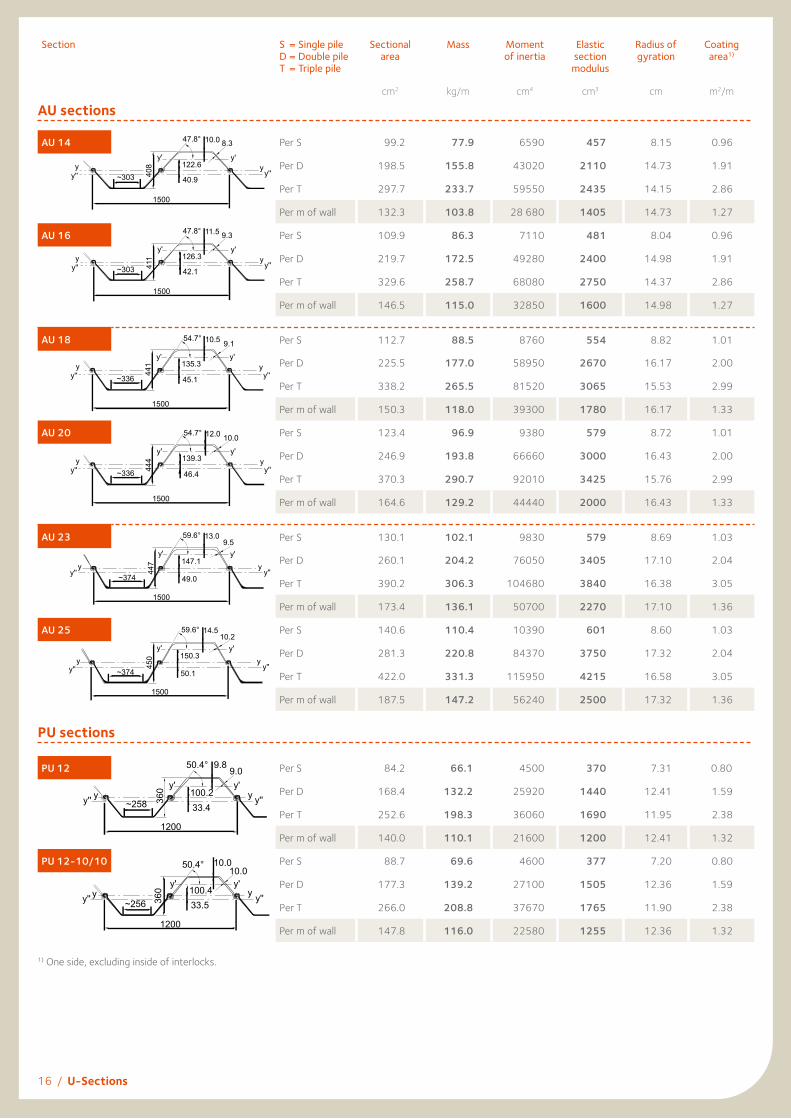
Section S = Single pile D = Double pile T = Triple pile
Sectional area
Mass Moment of inertia
Elastic section
modulus
Radius of gyration
Coating area1)
cm2 kg/m cm4 cm3 cm m2/m
AU sections
AU 14 Per S 99.2 77.9 6590 457 8.15 0.96
Per D 198.5 155.8 43020 2110 14.73 1.91
Per T 297.7 233.7 59550 2435 14.15 2.86
Per m of wall 132.3 103.8 28 680 1405 14.73 1.27
AU 16 Per S 109.9 86.3 7110 481 8.04 0.96
Per D 219.7 172.5 49280 2400 14.98 1.91
Per T 329.6 258.7 68080 2750 14.37 2.86
Per m of wall 146.5 115.0 32850 1600 14.98 1.27
AU 18 Per S 112.7 88.5 8760 554 8.82 1.01
Per D 225.5 177.0 58950 2670 16.17 2.00
Per T 338.2 265.5 81520 3065 15.53 2.99
Per m of wall 150.3 118.0 39300 1780 16.17 1.33
AU 20 Per S 123.4 96.9 9380 579 8.72 1.01
Per D 246.9 193.8 66660 3000 16.43 2.00
Per T 370.3 290.7 92010 3425 15.76 2.99
Per m of wall 164.6 129.2 44440 2000 16.43 1.33
AU 23 Per S 130.1 102.1 9830 579 8.69 1.03
Per D 260.1 204.2 76050 3405 17.10 2.04
Per T 390.2 306.3 104680 3840 16.38 3.05
Per m of wall 173.4 136.1 50700 2270 17.10 1.36
AU 25 Per S 140.6 110.4 10390 601 8.60 1.03
Per D 281.3 220.8 84370 3750 17.32 2.04
Per T 422.0 331.3 115950 4215 16.58 3.05
Per m of wall 187.5 147.2 56240 2500 17.32 1.36
PU sections
PU 12 Per S 84.2 66.1 4500 370 7.31 0.80
Per D 168.4 132.2 25920 1440 12.41 1.59
Per T 252.6 198.3 36060 1690 11.95 2.38
Per m of wall 140.0 110.1 21600 1200 12.41 1.32
PU 12-10/10 Per S 88.7 69.6 4600 377 7.20 0.80
Per D 177.3 139.2 27100 1505 12.36 1.59
Per T 266.0 208.8 37670 1765 11.90 2.38
Per m of wall 147.8 116.0 22580 1255 12.36 1.32
16 / U-Sections
1500
~303
y'y'
y''y
y''y
10.0 8.340
847.8°
40.9
122.6
bb
ts
h
AU 14
1500
~303
y'y'
y''y
y''y
11.5 9.3
411
42.1
126.3
bb
ts
h
AU 16
47.8°
1500
~336
y'y'
y''y
y''y
10.5 9.1
441
54.7°
45.1
135.3
bb
ts
h
AU 18
1500
~336
y'y'
y''y
y''y
12.0 10.0
444
54.7°
46.4
139.3
bb
ts
h
AU 20
1200
~258
y'y'y'' y y''y
9.89.0
360
50.4°
33.4100.2
bb
ts
h
PU 12
1200
~256
y'y'y'' y y''y
10.010.0
360
50.4°
33.5100.4
bb
ts
h
PU 12-10/10
1) One side, excluding inside of interlocks.
1500
~374
y'y'
y''y
y''y
13.09.5
447
59.6°
49.0
147.1
bb
ts
h
AU 23
1500
~374
y'y'
y''y
y''y
14.510.2
450
59.6°
50.1
150.3
bb
ts
h
AU 25
U-Sections / 17
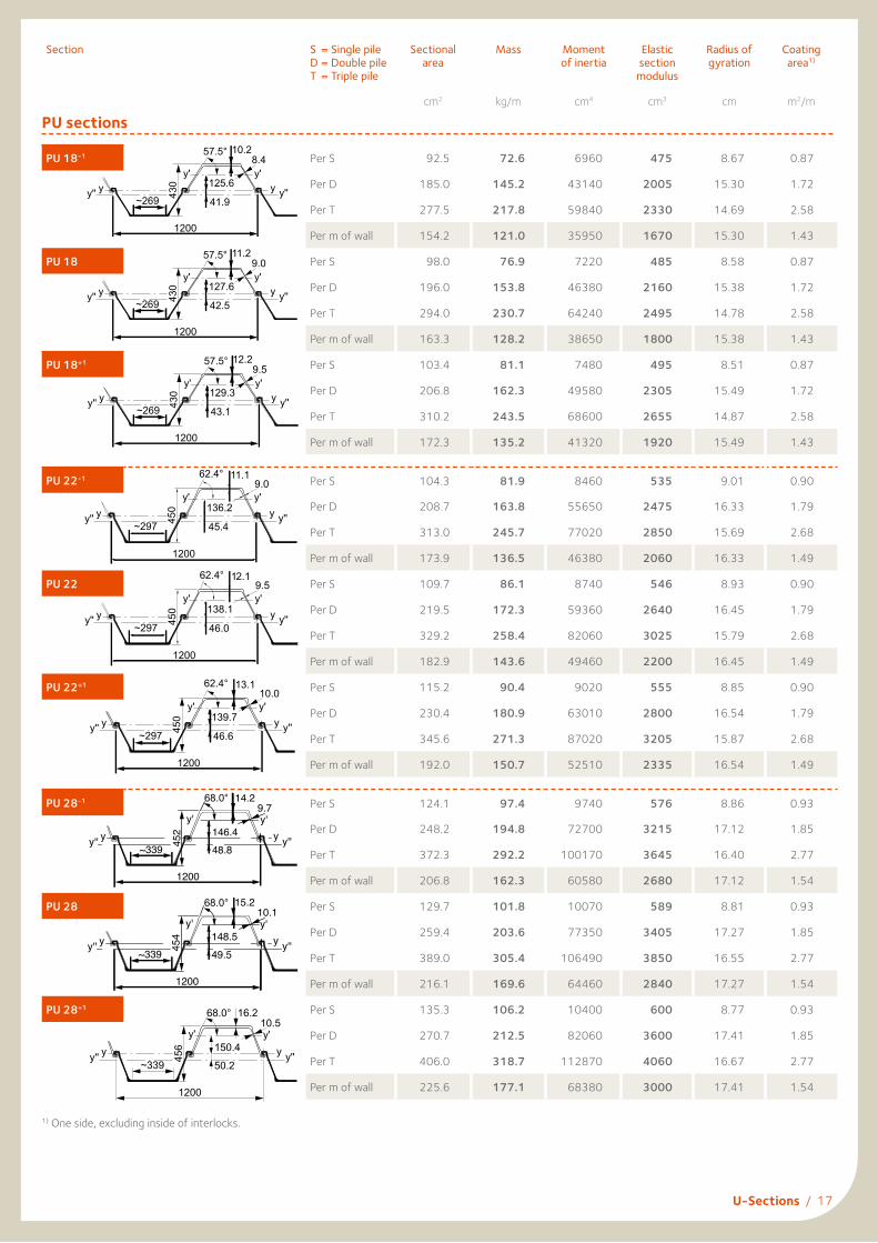
Sectionme S = Single pile D = Double pile T = Triple pile
Sectional area
Mass Moment of inertia
Elastic section
modulus
Radius of gyration
Coating area1)
cm2 kg/m cm4 cm3 cm m2/m
PU sections
PU 18-1 Per S 92.5 72.6 6960 475 8.67 0.87
Per D 185.0 145.2 43140 2005 15.30 1.72
Per T 277.5 217.8 59840 2330 14.69 2.58
Per m of wall 154.2 121.0 35950 1670 15.30 1.43
PU 18 Per S 98.0 76.9 7220 485 8.58 0.87
Per D 196.0 153.8 46380 2160 15.38 1.72
Per T 294.0 230.7 64240 2495 14.78 2.58
Per m of wall 163.3 128.2 38650 1800 15.38 1.43
PU 18+1 Per S 103.4 81.1 7480 495 8.51 0.87
Per D 206.8 162.3 49580 2305 15.49 1.72
Per T 310.2 243.5 68600 2655 14.87 2.58
Per m of wall 172.3 135.2 41320 1920 15.49 1.43
PU 22-1 Per S 104.3 81.9 8460 535 9.01 0.90
Per D 208.7 163.8 55650 2475 16.33 1.79
Per T 313.0 245.7 77020 2850 15.69 2.68
Per m of wall 173.9 136.5 46380 2060 16.33 1.49
PU 22 Per S 109.7 86.1 8740 546 8.93 0.90
Per D 219.5 172.3 59360 2640 16.45 1.79
Per T 329.2 258.4 82060 3025 15.79 2.68
Per m of wall 182.9 143.6 49460 2200 16.45 1.49
PU 22+1 Per S 115.2 90.4 9020 555 8.85 0.90
Per D 230.4 180.9 63010 2800 16.54 1.79
Per T 345.6 271.3 87020 3205 15.87 2.68
Per m of wall 192.0 150.7 52510 2335 16.54 1.49
PU 28-1 Per S 124.1 97.4 9740 576 8.86 0.93
Per D 248.2 194.8 72700 3215 17.12 1.85
Per T 372.3 292.2 100170 3645 16.40 2.77
Per m of wall 206.8 162.3 60580 2680 17.12 1.54
PU 28 Per S 129.7 101.8 10070 589 8.81 0.93
Per D 259.4 203.6 77350 3405 17.27 1.85
Per T 389.0 305.4 106490 3850 16.55 2.77
Per m of wall 216.1 169.6 64460 2840 17.27 1.54
PU 28+1 Per S 135.3 106.2 10400 600 8.77 0.93
Per D 270.7 212.5 82060 3600 17.41 1.85
Per T 406.0 318.7 112870 4060 16.67 2.77
Per m of wall 225.6 177.1 68380 3000 17.41 1.54
1200
~269
y'y'
y'' y y''y
12.29.5
430
57.5°
43.1
129.3
1) One side, excluding inside of interlocks.
1200
~297
y'y'
y'' y y''y
11.19.0
450
62.4°
45.4
136.2
bb
t s
h
PU 22
1200
~297
y'y'
y'' y y''y
12,19,5
450
62,4∞
46,0
138,1
1200
~297
y'y'
y'' y y''y
12.19.5
450
62.4°
46.0
138.1
bb
t s
h
PU 22
1200
~297
y'y'
y'' y y''y
12,19,5
450
62,4∞
46,0
138,1
PU 22+1.0
1200
~297
y'y'
y'' y y''y
13.110.0
450
62.4°
46.6
139.7
PU 28-1.0
1200
~339
y'y'
y'' y y''y
14.29.7
452
68.0°
48.8146.4
1200
~339
y'y'
y'' y y''y
15.210.1
454
68.0°
49.5148.5
PU 28+1.0
1200
~339
y'y'
y'' y y''y
16.210.5
456
68.0°
50.2
150.4
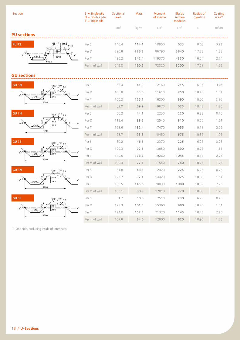
Sectionme S = Single pile D = Double pile T = Triple pile
Sectional area
Mass Moment of inertia
Elastic section
modulus
Radius of gyration
Coating area1)
cm2 kg/m cm4 cm3 cm m2/m
PU sections
PU 32 Per S 145.4 114.1 10950 633 8.68 0.92
Per D 290.8 228.3 86790 3840 17.28 1.83
Per T 436.2 342.4 119370 4330 16.54 2.74
Per m of wall 242.0 190.2 72320 3200 17.28 1.52
GU sections
GU 6N Per S 53.4 41.9 2160 215 6.36 0.76
Per D 106.8 83.8 11610 750 10.43 1.51
Per T 160.2 125.7 16200 890 10.06 2.26
Per m of wall 89.0 69.9 9670 625 10.43 1.26
GU 7N Per S 56.2 44.1 2250 220 6.33 0.76
Per D 112.4 88.2 12540 810 10.56 1.51
Per T 168.6 132.4 17470 955 10.18 2.26
Per m of wall 93.7 73.5 10450 675 10.56 1.26
GU 7S Per S 60.2 46.3 2370 225 6.28 0.76
Per D 120.3 92.5 13850 890 10.73 1.51
Per T 180.5 138.8 19260 1045 10.33 2.26
Per m of wall 100.3 77.1 11540 740 10.73 1.26
GU 8N Per S 61.8 48.5 2420 225 6.26 0.76
Per D 123.7 97.1 14420 925 10.80 1.51
Per T 185.5 145.6 20030 1080 10.39 2.26
Per m of wall 103.1 80.9 12010 770 10.80 1.26
GU 8S Per S 64.7 50.8 2510 230 6.23 0.76
Per D 129.3 101.5 15360 980 10.90 1.51
Per T 194.0 152.3 21320 1145 10.48 2.26
Per m of wall 107.8 84.6 12800 820 10.90 1.26
18 / U-Sections
1) One side, excluding inside of interlocks.
GU 7S
1200
~248
y'y'
y'' y y''y311
42.5°
29.0
87.0
7.2 6.9
GU 8N
1200
~248
y'y'
y'' y y''y312
42.5°
29.3
87.9
7.5 7.1
GU 8S
1200
~248
y'y'
y'' y y''y313
42.5°
29.8
89.4
8.0 7.5
GU 7N
1200
~248
y'y'
y'' y y''y310
42.5°
28.2
84.6
6.5 6.4
GU 6N
1200
~248
y'y'
y'' y y''y309
42.5°
27.6
82.7
6.0 6.0
bb
ts
h
PU 32
~342
1200
49.8
149.4
19.511.0
68.1°45
2yy''
y'y
y'
y''

U-Sections / 19
Sectionme S = Single pile D = Double pile T = Triple pile
Sectional area
Mass Moment of inertia
Elastic section
modulus
Radius of gyration
Coating area1)
cm2 kg/m cm4 cm3 cm m2/m
GU sections
GU 13N Per S 76.3 59.9 5440 395 8.44 0.85
Per D 152.6 119.8 31900 1525 14.46 1.69
Per T 228.9 179.7 44350 1785 13.92 2.53
Per m of wall 127.2 99.8 26590 1270 14.46 1.41
GU 14N Per S 81.9 64.3 5750 410 8.38 0.85
Per D 163.8 128.6 35290 1680 14.68 1.69
Per T 245.6 192.8 48970 1955 14.12 2.53
Per m of wall 136.5 107.1 29410 1400 14.68 1.41
GU 15N Per S 87.5 68.7 6070 425 8.33 0.85
Per D 175.1 137.4 38710 1835 14.87 1.69
Per T 262.6 206.2 53640 2130 14.29 2.53
Per m of wall 145.9 114.5 32260 1530 14.87 1.41
GU 16N Per S 92.5 72.6 6960 475 8.67 0.87
Per D 185.0 145.2 43140 2005 15.30 1.72
Per T 277.5 217.8 59840 2330 14.69 2.58
Per m of wall 154.2 121.0 35950 1670 15.30 1.43
GU 18N Per S 98.0 76.9 7220 485 8.58 0.87
Per D 196.0 153.8 46380 2160 15.38 1.72
Per T 294.0 230.7 64240 2495 14.78 2.58
Per m of wall 163.3 128.2 38650 1800 15.38 1.43
GU 20N Per S 103.4 81.1 7480 495 8.51 0.87
Per D 206.8 162.3 49580 2305 15.49 1.72
Per T 310.2 243.5 68600 2655 14.87 2.58
Per m of wall 172.3 135.2 41320 1920 15.49 1.43
GU 16-400 Per S 78.9 62.0 2950 265 6.11 0.65
Per D 157.9 123.9 18060 1245 10.70 1.28
Per T 236.8 185.9 25060 1440 10.29 1.92
Per m of wall 197.3 154.9 22580 1560 10.70 1.60
GU 18-400 Per S 88.3 69.3 3290 290 6.10 0.65
Per D 176.7 138.7 20870 1430 10.87 1.28
Per T 265.0 208.0 28920 1645 10.45 1.92
Per m of wall 220.8 173.3 26090 1785 10.87 1.60
1) One side, excluding inside of interlocks.
800
~252
y'y'
y'' y y''y290
82.1°
29.3
87.8
12.79.4
GU 16-400G62
800
~252
y'y'
y'' y y''y292
82.1°
30.0
90.0
15.09.7
GU 18-400G62/P2
1200
~250
y'y'
y''y y''y
9.07.4
418
54.3°
39.1117.4
1200
~250
y'y'
y''y y''y
10.08.0
420
54.3°
40.2120.5
1200
~269
y'y'
y'' y y''y
12.29.5
430
57.5°
43.1
129.3
1200
~250
y'y'
y''y y''y
11.08.6
422
54.3°
41.1
123.2
20 / U-Sections
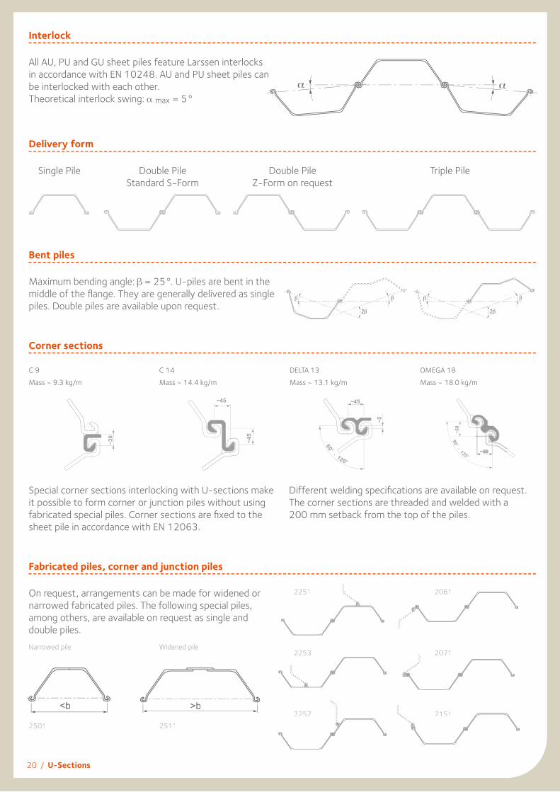
Interlock
All AU, PU and GU sheet piles feature Larssen interlocksin accordance with EN 10248. AU and PU sheet piles can be interlocked with each other. Theoretical interlock swing: max = 5°
Delivery form
Bent piles
Maximum bending angle: = 25°. U-piles are bent in the middle of the fl ange. They are generally delivered as single piles. Double piles are available upon request.
Corner sections
C 9Mass ~ 9.3 kg/m
C 14Mass ~ 14.4 kg/m
DELTA 13Mass ~ 13.1 kg/m
OMEGA 18Mass ~ 18.0 kg/m
Special corner sections interlocking with U-sections make it possible to form corner or junction piles without using fabricated special piles. Corner sections are fi xed to the sheet pile in accordance with EN 12063.
Different welding specifi cations are available on request. The corner sections are threaded and welded with a200 mm setback from the top of the piles.
Single Pile
Fabricated piles, corner and junction piles
On request, arrangements can be made for widened or narrowed fabricated piles. The following special piles, among others, are available on request as single and double piles.
α α
Double PileStandard S-Form
Double PileZ-Form on request
Triple Pile
-
-
Narrowed pile
2501
Widened pile
2511
2251
2253
2257
2061
2071
2151<b >b
U-Sections / 21
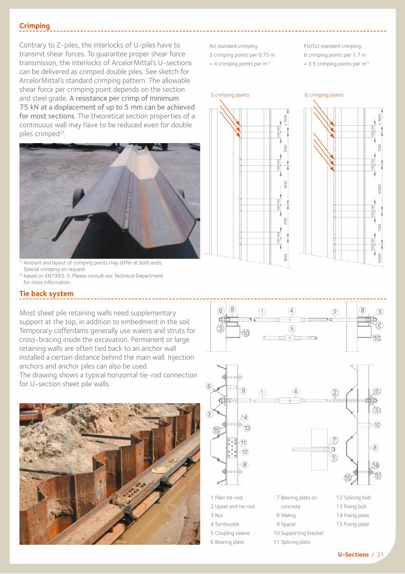
Crimping
Contrary to Z-piles, the interlocks of U-piles have to transmit shear forces. To guarantee proper shear force transmisson, the interlocks of ArcelorMittal’s U-sections can be delivered as crimped double piles. See sketch for ArcelorMittal’s standard crimping pattern. The allowable shear force per crimping point depends on the section and steel grade. A resistance per crimp of minimum 75 kN at a displacement of up to 5 mm can be achieved for most sections. The theoretical section properties of a continuous wall may have to be reduced even for double piles crimped2).
Tie back system
Most sheet pile retaining walls need supplementary support at the top, in addition to embedment in the soil. Temporary cofferdams generally use walers and struts for cross-bracing inside the excavation. Permanent or large retaining walls are often tied back to an anchor wall installed a certain distance behind the main wall. Injection anchors and anchor piles can also be used.The drawing shows a typical horizontal tie-rod connection for U-section sheet pile walls.
AU standard crimping:3 crimping points per 0.75 m= 4 crimping points per m1)
PU/GU standard crimping:6 crimping points per 1.7 m= 3.5 crimping points per m1)
38
6
100
2
110
6
3
8
3
38
112
11
1333
143
96
1 4
6 8 1
5
4
1 Plain tie-rod2 Upset end tie-rod3 Nut4 Turnbuckle5 Coupling sleeve6 Bearing plate
7 Bearing plate on concrete
8 Waling 9 Spacer10 Supporting bracket11 Splicing plate
12 Splicing bolt13 Fixing bolt14 Fixing plate15 Fixing plate
3 crimping points 6 crimping points
1) Amount and layout of crimping points may differ at both ends. Special crimping on request.
2) based on EN1993-5. Please consult our Technical Department for more information.
< 5
00
7
00
100
100
80
0
100
100
70
0
100
100
80
0
100
100
< 5
00
7
00
100
100
10
00
100
100
70
0
100
100
10
00
100
100

22 / AS 500
AS 500 straight web sectionsAS 500 straight web sheet piles are designed to form closed cylindrical structures retaining a soil fi ll. The stability of the cells consisting of a steel envelope and an internal body of soil is guaranteed by their own weight. Straight web sheet piles are mostly used on projects where rock layers are close to ground level or where anchoring would be diffi cult or impossible. Straight web sheet pile structures are made of circular cells or diaphragm cells, depending on the site characteristics or the particular requirements of the project. The forces developing in these sheet pile sections are essentially horizontal tensile forces requiring an interlock strength corresponding to the horizontal force in the web of the pile. AS 500 interlocks comply with EN 10248. Please refer to our brochure “AS 500 Straight web steel sheet piles - design & execution manual” for further details.
The following interlock strengths can be achieved for anS 355 GP steel grade:Section Fmax [kN/m]
AS 500-9.5 3000
AS 500-11.0 3500
AS 500-12.0 4500
AS 500-12.5 5500
AS 500-12.7 5500* Fmax = 5000 kN/m upon request
For verifi cation of the strength of piles, both yielding of the web and failure of the interlock should be considered.
General cargo berth, Bal Haf, Yemen
Section Nominalwidth 1)
bmm
Webthickness
tmm
Deviationangle 2)
δ°
Perimeter
cm
Steel section
cm2
Mass
kg/m
Mass per m2 of wall
kg/m2
Moment of inertia
cm4
Section modulus
cm3
Coating area 3)
m2/m
AS 500-9.5 500 9.5 4.5 138 81.3 63.8 128 168 46 0.58
AS 500-11.0 500 11.0 4.5 139 90.0 70.6 141 186 49 0.58
AS 500-12.0 500 12.0 4.5 139 94.6 74.3 149 196 51 0.58
AS 500-12.5 500 12.5 4.5 139 97.2 76.3 153 201 51 0.58
AS 500-12.7 500 12.7 4.5 139 98.2 77.1 154 204 51 0.58
1) The effective width to be taken into account for design purposes (lay-out) is 503 mm for all AS 500 sheet piles.2) Max. deviation angle 4.0° for pile length > 20 m.3) One side, excluding inside of interlocks.
Bridge construction, South Korea
(single pile) (single pile)
thumb
*

AS 500 / 23
Junction piles and bent piles
Junction piles that join circular cells and intermediary arcs can be provided. Bent piles are pre-bent at the mill. If the deviation angle exceeds 4.5° (4.0° if L > 20 m), bent piles can be used to set up structures with small radii.
Circular cell construction
1. Installation of template 2. Threading until cell closure 3. Driving
Types of cells
Circular cells with 35° junction piles and one or two connecting arcs. Diaphragm cells with 120° junction piles.
IC
β
PC
β
Berthing facility, Canada Lock, Arkansas, USA

24 / AS 500
Equivalent width
The equivalent width we which is required for stability verifi cation determines the geometry of the chosen cellular construction.
Geometry of circular cells
Once the equivalent width has been determined, the geometry of the cells can be defi ned. This can be done with the help of tables or with computer programs.
Junction piles with angles θ between 30° and 45°, as well as θ = 90°, are available on request.
The table below shows a short selection of circular cells with 2 arcs and standard junction piles with θ = 35°.
System length x
60°60°r
we
x = r
dlc
120°
120°
c
• for diaphragm cellsThe equivalent width we is defi ned as:we = diaphragm wall length (dl) + 2 · c
• for circular cells
The equivalent width we is defi ned as:
we = Area within 1 cell + Area within 1 (or 2) arc(s)System length x
The ratio Ra indicates how economical the chosen circular cell will be.
It is defi ned as follows
Ra = Development 1 cell + Development 1 (or 2) arc(s)System length x
we
β
Nra
dy
x
α
αMM
S
S
S
S
L
L
θ
rm
Nb. of piles per Geometrical values Interlock deviation Design values
Cell Arc System Cell Arc 2 Arcs
Totalpcs.
Lpcs.
Mpcs.
Spcs.
Npcs. pcs.
d = 2·rmm
ram
xm
dym
α°
β°
δm°
δa°
wem
Ra
100 33 15 1 25 150 16.01 4.47 22.92 0.16 28.80 167.60 3.60 6.45 13.69 3.34104 35 15 1 27 158 16.65 4.88 24.42 0.20 27.69 165.38 3.46 5.91 14.14 3.30108 37 15 1 27 162 17.29 4.94 25.23 0.54 26.67 163.33 3.33 5.83 14.41 3.27112 37 17 1 27 166 17.93 4.81 25.25 0.33 28.93 167.86 3.21 6.00 15.25 3.35116 37 19 1 27 170 18.57 4.69 25.27 0.13 31.03 172.07 3.10 6.15 16.08 3.42120 39 19 1 29 178 19.21 5.08 26.77 0.16 30.00 170.00 3.00 5.67 16.54 3.38124 41 19 1 29 182 19.85 5.14 27.59 0.50 29.03 168.06 2.90 5.60 16.82 3.35128 43 19 1 31 190 20.49 5.55 29.09 0.53 28.13 166.25 2.81 5.20 17.27 3.32132 43 21 1 31 194 21.13 5.42 29.11 0.33 30.00 170.00 2.73 5.31 18.10 3.39136 45 21 1 33 202 21.77 5.82 30.61 0.36 29.12 168.24 2.65 4.95 18.56 3.35140 45 23 1 33 206 22.42 5.71 30.62 0.17 30.86 171.71 2.57 5.05 19.39 3.42144 47 23 1 33 210 23.06 5.76 31.45 0.50 30.00 170.00 2.50 5.00 19.67 3.39148 47 25 1 35 218 23.70 5.99 32.13 0.00 31.62 173.24 2.43 4.81 20.67 3.44152 49 25 1 35 222 24.31 6.05 32.97 0.34 30.79 171.58 2.37 4.77 20.95 3.42
rm = radius of the main cellra = radius of the connecting arcsθ = angle between the main cell and
the connecting arcx = system lengthdy = positive or negative offset betweenffset betweenf
the connecting arcs and the tangentplanes of the main cells
we = equivalent width
Equi
vale
ntw
idth
we
Equi
vale
ntw
idth
we
System length x
System length x
Area
Development
c
circular cell with 2 arcs
circular cell with 1 arc
b/2b/2
b/2
θ = 35˚
Standard solution

AS 500 / 25
Geometry of diaphragm cells
60°
M
r
N dlwe
dy
x = r
c
c
θθ = 120°
150
Standard solution
Geometry diaphragm wall Geometry arc (Standard solution)
Number of piles Wall length Number of piles RadiusSystem length Arc height
Equivalent archeight Interlock deviation
Npcs.
dlm
Mpcs.
x=rm
dym
cm
δa°
11 5.83 11 5.57 0.75 0.51 5.1713 6.84 13 6.53 0.87 0.59 4.4115 7.85 15 7.49 1.00 0.68 3.8517 8.85 17 8.45 1.13 0.77 3.4119 9.86 19 9.41 1.26 0.86 3.0621 10.86 21 10.37 1.39 0.94 2.7823 11.87 23 11.33 1.52 1.03 2.5425 12.88 25 12.29 1.65 1.12 2.3427 13.88 27 13.26 1.78 1.20 2.1729 14.89 29 14.22 1.90 1.29 2.0331 15.89 31 15.18 2.03 1.38 1.9033 16.90 33 16.14 2.16 1.46 1.7935 17.91 35 17.10 2.29 1.55 1.6937 18.91 37 18.06 2.42 1.64 1.6039 19.92 39 19.02 2.55 1.73 1.5241 20.92 41 19.98 2.68 1.81 1.4443 21.93 43 20.94 2.81 1.90 1.3845 22.9447 23.9449 24.9551 25.9553 26.9655 27.9757 28.9759 29.98
Tugboat berth, Panama Canal, Panama Marina breakwater, Costa Rica
r = radiusθ = angle between the arc and
the diaphragmwe = equivalent width, with we = dl+2 ·cdy = arc heightdl = diaphragm wall lengthx = system lengthc = equivalent arc height
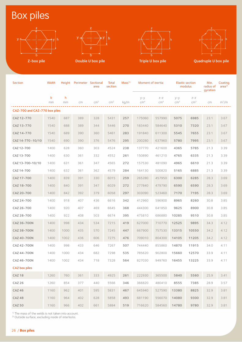
26 / Box piles
Section Width Height Perimeter Sectional area
Total section
Mass1) Moment of inertia
Elastic section modulus
Min. radius of gyration
Coating area2)
b mm
h mm
cm
cm2
cm2
kg/m
y-y cm4
z-z cm4
y-y cm3
z-z cm3
cm
m2/m
CAZ-700 and CAZ-770 box piles
CAZ 12-770 1540 687 389 328 5431 257 175060 557990 5075 6985 23.1 3.67
CAZ 13-770 1540 688 389 344 5446 270 183440 584640 5310 7320 23.1 3.67
CAZ 14-770 1540 689 390 360 5461 283 191840 611300 5545 7655 23.1 3.67
CAZ 14-770 -10/10 1540 690 390 376 5476 295 200280 637960 5780 7995 23.1 3.67
CAZ 12-700 1400 628 360 303 4524 238 137770 421600 4365 5785 21.3 3.39
CAZ 13-700 1400 630 361 332 4552 261 150890 461210 4765 6335 21.3 3.39
CAZ 13-700-10/10 1400 631 361 347 4565 272 157530 481090 4965 6610 21.3 3.39
CAZ 14-700 1400 632 361 362 4579 284 164130 500820 5165 6885 21.3 3.39
CAZ 17-700 1400 839 391 330 6015 259 265280 457950 6300 6285 28.3 3.69
CAZ 18-700 1400 840 391 347 6029 272 277840 479790 6590 6590 28.3 3.69
CAZ 20-700 1400 842 392 379 6058 297 303090 523460 7170 7195 28.3 3.69
CAZ 24-700 1400 918 407 436 6616 342 412960 596900 8965 8260 30.8 3.85
CAZ 26-700 1400 920 407 469 6645 368 444300 641850 9625 8900 30.8 3.85
CAZ 28-700 1400 922 408 503 6674 395 475810 686880 10285 9510 30.8 3.85
CAZ 36-700N 1400 998 434 534 7215 419 627000 710770 12525 9895 34.3 4.12
CAZ 38-700N 1400 1000 435 570 7245 447 667900 757530 13315 10550 34.2 4.12
CAZ 40-700N 1400 1002 436 606 7275 476 709010 804300 14105 11205 34.2 4.12
CAZ 42-700N 1400 998 433 646 7267 507 744440 855860 14870 11915 34.0 4.11
CAZ 44-700N 1400 1000 434 682 7298 535 785620 902800 15660 12570 33.9 4.11
CAZ 46-700N 1400 1002 434 718 7328 564 827030 949760 16455 13225 33.9 4.11
CAZ box piles
CAZ 18 1260 760 361 333 4925 261 222930 365500 5840 5560 25.9 3.41
CAZ 26 1260 854 377 440 5566 346 366820 480410 8555 7385 28.9 3.57
CAZ 46 1160 962 401 595 5831 467 645940 527590 13380 8825 32.9 3.81
CAZ 48 1160 964 402 628 5858 493 681190 556070 14080 9300 32.9 3.81
CAZ 50 1160 966 402 661 5884 519 716620 584560 14780 9780 32.9 3.81
Box piles
1) The mass of the welds is not taken into account.2) Outside surface, excluding inside of interlocks.
Z-box pile Double U box pile Triple U box pile Quadruple U box pile
z
hyy
zb
y y h
z
z
b b
hyy
z
zb
hyy
z
z

Box piles / 27
Section Width Height Perimeter Sectional area
Total section
Mass1) Moment of inertia
Elastic sectionmodulus
Min.radius ofgyration
Coatingarea2)
bmm
hmm cm cm2 cm2 kg/m
y-ycm4
z-zcm4
y-y cm3
z-zcm3 cm m2/m
CAU double box piles
CAU 14-2 750 451 230 198 2598 155.8 54400 121490 2415 3095 16.6 2.04
CAU 16-2 750 454 231 220 2620 172.5 62240 130380 2745 3325 16.8 2.04
CAU 18-2 750 486 239 225 2888 177.0 73770 142380 3035 3625 18.1 2.14
CAU 20-2 750 489 240 247 2910 193.8 83370 151220 3405 3850 18.4 2.14
CAU 23-2 750 492 244 260 3013 204.2 94540 157900 3845 4020 19.1 2.19
CAU 25-2 750 495 245 281 3034 220.8 104810 166600 4235 4240 19.3 2.19
CU double box piles
CU 12-2 600 403 198 168 1850 132.2 34000 70000 1685 2205 14.2 1.72
CU 12 -10/10-2 600 403 198 177 1850 139.2 35580 73460 1765 2315 14.2 1.72
CU 18-2 600 473 212 196 2184 153.8 58020 78300 2455 2470 17.2 1.86
CU 22-2 600 494 220 219 2347 172.3 73740 88960 2985 2800 18.3 1.94
CU 28-2 600 499 226 259 2468 203.6 96000 103560 3850 3260 19.2 2.00
CU 32-2 600 499 223 291 2461 228.3 108800 109200 4360 3435 19.3 1.97
CGU double box piles
CGU 6N-2 600 347 187 107 1590 83.8 15310 47040 885 1490 12.0 1.62
CGU 7N-2 600 348 187 112 1596 88.2 16510 48530 950 1535 12.1 1.62
CGU 7S-2 600 349 188 120 1604 92.5 18210 50630 1045 1605 12.3 1.62
CGU 8N-2 600 350 188 124 1607 97.1 18940 51520 1085 1630 12.4 1.62
CGU 8S-2 600 351 188 129 1612 101.5 20170 53020 1150 1680 12.5 1.62
CGU 13N-2 600 459 205 153 2068 119.8 39890 62650 1740 1980 16.2 1.79
CGU 14N-2 600 461 205 164 2079 128.6 44070 65550 1910 2075 16.4 1.79
CGU 15N-2 600 463 206 175 2090 137.4 48290 68580 2085 2170 16.6 1.79
CGU 18N-2 600 473 212 196 2184 153.8 58020 78300 2455 2470 17.2 1.86
CGU 16-400 400 336 169 158 1170 123.9 25270 31900 1505 1465 12.7 1.40
CGU 18-400 400 340 169 177 1187 138.7 29520 34560 1735 1585 12.9 1.401) The mass of the welds is not taken into account.2) Outside surface, excluding inside of interlocks.
28 / Box piles
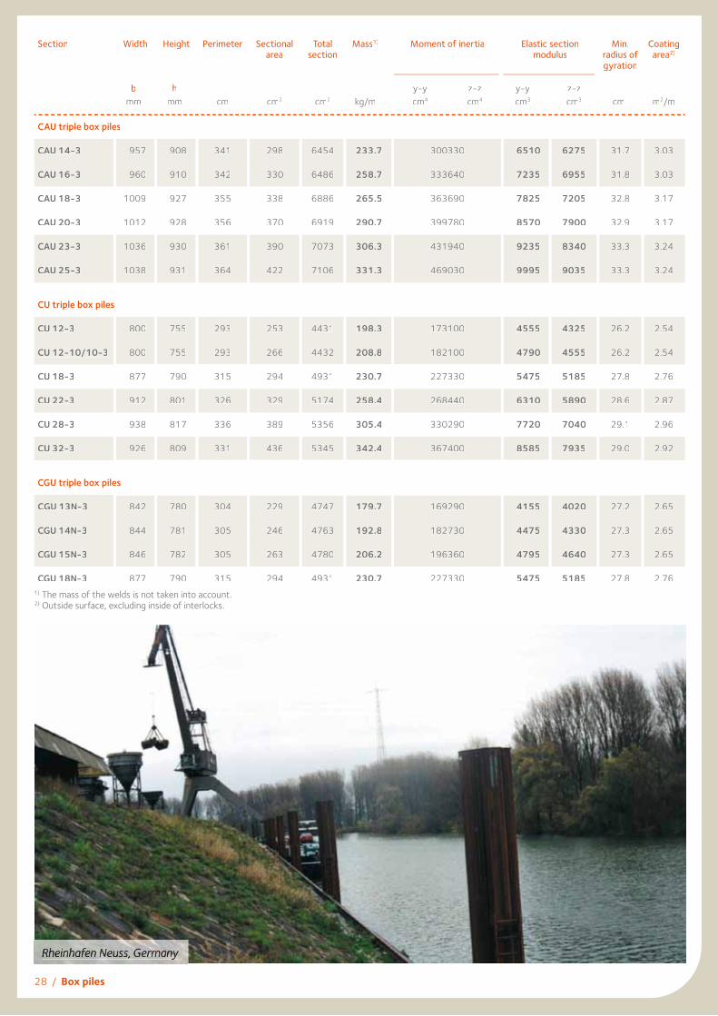
Section Width Height Perimeter Sectional area
Total section
Mass1) Moment of inertia
Elastic sectionmodulus
Min.radius ofgyration
Coatingarea2)
bmm
hmm cm cm2 cm2 kg/m
y-ycm4
z-zcm4
y-ycm3
z-zcm3 cm m2/m
CAU triple box piles
CAU 14-3 957 908 341 298 6454 233.7 300330 6510 6275 31.7 3.03
CAU 16-3 960 910 342 330 6486 258.7 333640 7235 6955 31.8 3.03
CAU 18-3 1009 927 355 338 6886 265.5 363690 7825 7205 32.8 3.17
CAU 20-3 1012 928 356 370 6919 290.7 399780 8570 7900 32.9 3.17
CAU 23-3 1036 930 361 390 7073 306.3 431940 9235 8340 33.3 3.24
CAU 25-3 1038 931 364 422 7106 331.3 469030 9995 9035 33.3 3.24
CU triple box piles
CU 12-3 800 755 293 253 4431 198.3 173100 4555 4325 26.2 2.54
CU 12-10/10-3 800 755 293 266 4432 208.8 182100 4790 4555 26.2 2.54
CU 18-3 877 790 315 294 4931 230.7 227330 5475 5185 27.8 2.76
CU 22-3 912 801 326 329 5174 258.4 268440 6310 5890 28.6 2.87
CU 28-3 938 817 336 389 5356 305.4 330290 7720 7040 29.1 2.96
CU 32-3 926 809 331 436 5345 342.4 367400 8585 7935 29.0 2.92
CGU triple box piles
CGU 13N-3 842 780 304 229 4747 179.7 169290 4155 4020 27.2 2.65
CGU 14N-3 844 781 305 246 4763 192.8 182730 4475 4330 27.3 2.65
CGU 15N-3 846 782 305 263 4780 206.2 196360 4795 4640 27.3 2.65
CGU 18N-3 877 790 315 294 4931 230.7 227330 5475 5185 27.8 2.76
Rheinhafen Neuss, Germany
1) The mass of the welds is not taken into account.2) Outside surface, excluding inside of interlocks.

Box piles / 29
Section Width Height Perimeter Sectionalarea
Total section
Mass1) Moment of inertia
Elastic sectionmodulus
Min.radius ofgyration
Coatingarea2)
bmm
hmm cm cm2 cm2 kg/m
y-ycm4
z-zcm4
y-ycm3
z-zcm3 cm m2/m
CAU quadruple box piles
CAU 14-4 1222 1222 453 397 11150 311.6 692030 11325 41.7 4.02
CAU 16-4 1225 1225 454 440 11193 345.0 770370 12575 41.8 4.02
CAU 18-4 1258 1258 471 451 11728 354.0 826550 13140 42.8 4.20
CAU 20-4 1261 1261 472 494 11771 387.6 910010 14430 42.9 4.20
CAU 23-4 1263 1263 481 520 11977 408.4 979870 15510 43.4 4.30
CAU 25-4 1266 1266 482 563 12020 441.6 1064910 16820 43.5 4.30
CU quadruple box piles
CU 12-4 1025 1025 388 337 7565 264.4 394000 7690 34.2 3.36
CU 12-10/10-4 1025 1025 388 355 7565 278.4 414830 8095 34.2 3.36
CU 18-4 1095 1095 417 392 8231 307.6 507240 9270 36.0 3.65
CU 22-4 1115 1115 432 439 8556 344.6 593030 10635 36.8 3.80
CU 28-4 1120 1120 445 519 8799 407.2 725730 12955 37.4 3.93
CU 32-4 1120 1120 440 582 8782 456.6 811100 14480 37.3 3.87
CGU quadruple box piles
CGU 13N-4 1079 1079 403 305 7975 239.6 379350 7035 35.3 3.51
CGU 14N-4 1081 1081 404 328 7997 257.1 409870 7585 35.4 3.51
CGU 15N-4 1083 1083 404 350 8020 274.9 440770 8145 35.5 3.51
CGU 18N-4 1095 1095 417 392 8231 307.6 507240 9270 36.0 3.65
Changxin dry dock, Shanghai, China
1) The mass of the welds is not taken into account.2) Outside surface, excluding inside of interlocks.

30 / Jagged wall
Jagged wall
AZ jagged wall: AZ sections threaded in reverse may form arrangements for special applications. The jagged wall arrangement represents a very economical solution for sealing screens (reduced height, reliable thickness, low driving resistance).
AZ jagged wallSection Width Height Sectional
areaMass Moment
of inertiaElastic section
modulusCoating area1)
b mm
h mm cm2/m kg/m2 cm4/m cm3/m m2/m2
AZ-700 and AZ-770
AZ 12-770 826 181 112 88 2330 255 1.12
AZ 13-770 826 182 117 92 2460 270 1.12
AZ 14-770 826 182 123 96 2600 285 1.12
AZ 14-770-10/10 826 183 128 100 2730 300 1.12
AZ 12-700 751 182 115 90 2410 265 1.13
AZ 13-700 751 183 126 99 2690 295 1.13
AZ 13-700-10/10 751 183 131 103 2830 310 1.13
AZ 14-700 751 184 136 107 2970 325 1.13
AZ 17-700 795 212 117 92 3690 330 1.16
AZ 18-700 795 212 123 96 3910 350 1.16
AZ 19-700 795 213 128 101 4120 365 1.16
AZ 20-700 795 214 134 105 4330 385 1.16
AZ 24-700 813 241 150 118 5970 495 1.19
AZ 26-700 813 242 161 127 6500 535 1.19
AZ 28-700 813 243 172 135 7030 580 1.19
AZ 36-700N 834 296 181 142 11900 805 1.23
AZ 38-700N 834 298 193 152 12710 855 1.23
AZ 40-700N 834 299 205 161 13530 905 1.23
AZ 42-700N 834 300 217 170 14650 975 1.24
AZ 44-700N 834 301 229 180 15460 1025 1.24
AZ 46-700N 834 302 241 189 16280 1075 1.24
AZ
AZ 18 714 225 133 104 4280 380 1.19
AZ 18-10/10 714 225 139 109 4500 400 1.19
AZ 26 736 238 169 133 6590 555 1.21
AZ 46 725 308 233 183 16550 1070 1.30
AZ 48 725 310 245 193 17450 1125 1.30
AZ 50 725 312 258 202 18370 1180 1.30
b
h
1) One side, excluding inside of interlocks.

Jagged wall / 31
U jagged wall
An arrangement of U-sheet piles forming a jagged wall offers economic solutions where high inertia and section modulus are needed. The fi nal choice of section has to include drivability criteria. The statical values given below assume the solidarisation of the driving element, i.e. double pile. The OMEGA 18 section is normallythreaded and welded at the mill, either by tack weld
(no contribution to the section modulus of the jagged wall) or by an appropriately designed weld (full contribution to the section modulus).For walls with an anchorage or strut system, stiffeners have to be provided at the support levels.
90°
90°
OMEGA 18A 18A
driving element
b
h
Section Width Height Mass Momentof inertia1)
Elastic sectionmodulus1)
Static moment
bmm
hmm kg/m2
withoutOmega 18
cm4/m
withOmega 18
cm4/m
withoutOmega 18
cm3/m
withOmega 18
cm3/m
withoutOmega 18
cm3/m
withOmega 18
cm3/m
AU jagged wall
AU 14 1135 1115 153 275830 334350 5075 5995 6160 7250
AU 16 1135 1115 168 307000 365520 5650 6555 6870 7960
AU 18 1135 1136 172 329320 387840 5795 6825 7180 8270
AU 20 1135 1139 187 362510 421030 6365 7395 7920 9005
AU 23 1135 1171 196 390650 449160 6675 7675 8470 9560
AU 25 1135 1173 211 424510 483020 7240 8235 9215 10300
PU jagged wall
PU 12 923 903 163 189000 229900 4275 5090 5175 6245
PU 12-10/10 923 903 170 198850 245250 4495 5430 5450 6525
PU 18 923 955 186 244340 290750 5120 6090 6430 7500
PU 22 923 993 206 285880 332290 5760 6690 7380 8450
PU 28 923 1028 240 349710 396110 6805 7710 8925 10000
PU 32 923 1011 267 389300 432400 7705 8560 10025 11095
GU jagged wall
GU 13N 923 918 149 183920 230360 4005 5015 4890 5965
GU 14N 923 920 159 198710 245140 4320 5330 5285 6360
GU 15N 923 921 168 213680 260120 4640 5645 5685 6760
GU 18N 923 955 186 244340 290750 5120 6090 6430 7500
1) The moment of inertia and elastic section moduli assume correct shear force transfer across the interlock on the neutral axis.
32 / Combined wall
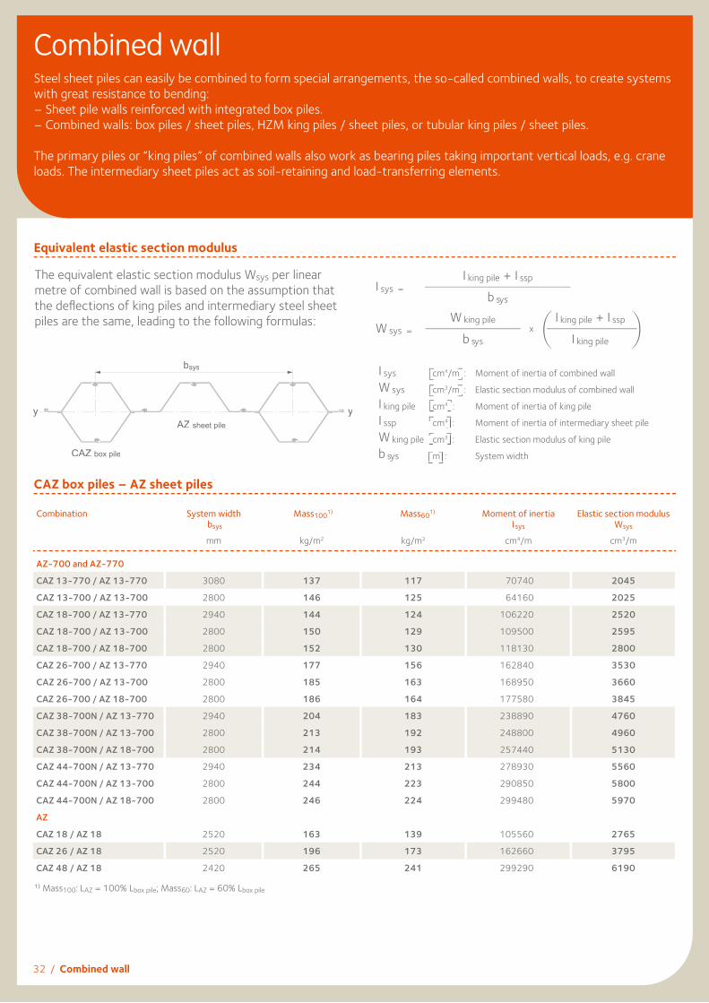
Equivalent elastic section modulus
The equivalent elastic section modulus Wsys per linear metre of combined wall is based on the assumption that the defl ections of king piles and intermediary steel sheet piles are the same, leading to the following formulas:
Combined wallSteel sheet piles can easily be combined to form special arrangements, the so-called combined walls, to create systems with great resistance to bending: – Sheet pile walls reinforced with integrated box piles.– Combined walls: box piles / sheet piles, HZM king piles / sheet piles, or tubular king piles / sheet piles.
The primary piles or “king piles” of combined walls also work as bearing piles taking important vertical loads, e.g. crane loads. The intermediary sheet piles act as soil-retaining and load-transferring elements.
CAZ box piles – AZ sheet piles
I sys =I king pile + I ssp
b sys
Combination System width bsys
Mass1001) Mass601) Moment of inertiaI sys
Elastic section modulusWsys
mm kg/m2 kg/m2 cm4/m cm3/m
AZ-700 and AZ-770
CAZ 13-770 / AZ 13-770 3080 137 117 70740 2045
CAZ 13-700 / AZ 13-700 2800 146 125 64160 2025
CAZ 18-700 / AZ 13-770 2940 144 124 106220 2520
CAZ 18-700 / AZ 13-700 2800 150 129 109500 2595
CAZ 18-700 / AZ 18-700 2800 152 130 118130 2800
CAZ 26-700 / AZ 13-770 2940 177 156 162840 3530
CAZ 26-700 / AZ 13-700 2800 185 163 168950 3660
CAZ 26-700 / AZ 18-700 2800 186 164 177580 3845
CAZ 38-700N / AZ 13-770 2940 204 183 238890 4760
CAZ 38-700N / AZ 13-700 2800 213 192 248800 4960
CAZ 38-700N / AZ 18-700 2800 214 193 257440 5130
CAZ 44-700N / AZ 13-770 2940 234 213 278930 5560
CAZ 44-700N / AZ 13-700 2800 244 223 290850 5800
CAZ 44-700N / AZ 18-700 2800 246 224 299480 5970
AZ
CAZ 18 / AZ 18 2520 163 139 105560 2765
CAZ 26 / AZ 18 2520 196 173 162660 3795
CAZ 48 / AZ 18 2420 265 241 299290 6190
1) Mass100: LAZ = 100% Lbox pile; Mass60: LAZ = 60% Lbox pile
W sys =W king pile
xI king pile + I ssp
b sys I king pile
I sys cm4/m : Moment of inertia of combined wallW sys cm3/m : Elastic section modulus of combined wallI king pile cm4 : Moment of inertia of king pileI ssp cm4 : Moment of inertia of intermediary sheet pileW king pile cm3 : Elastic section modulus of king pileb sys m : System width
/m : Moment of inertia of combined wallsys cm
/m : Elastic section modulus of combined wallsys cm
: Moment of inertia of king pileking pile cm
: Moment of inertia of intermediary sheet pilessp cm
: Elastic section modulus of king pileking pile cm
sys m : System widthsys m : System width
bsys
yy
CAZ box pile
AZ sheet pile

Combined wall / 33
U box piles – U sheet piles
Type of reinforcement:
- Heightwise: full or partial height.- Lengthwise: total length 1/1 or
partial length 1/2, 1/3, 1/4.
Please contact our Technical Departmentfor other combinations (e.g. 2/4).
Section 1 / 1
1 / 2
1 / 3
1 / 4
Mass
kg/m2
Momentof inertia
cm4/m
Elasticsection
moduluscm3/m
Mass
kg/m2
Momentof inertia
cm4/m
Elastic section
moduluscm3/m
Mass
kg/m2
Momentof inertia
cm4/m
Elastic section
moduluscm3/m
Mass
kg/m2
Momentof inertia
cm4/m
Elastic section
moduluscm3/m
CAU box piles / AU sheet piles
AU 14 208 72530 3220 156 40660 1805 139 43300 1920 130 37980 1550
AU 16 230 82990 3660 173 46230 2035 153 49560 2185 144 43440 1755
AU 18 236 98360 4045 177 55020 2260 157 58990 2425 148 51760 1950
AU 20 258 111160 4545 194 61830 2525 172 66680 2725 162 58460 2180
AU 23 272 126050 5125 204 69580 2830 182 75820 3080 170 66410 2435
AU 25 294 139750 5645 221 76800 3105 196 84080 3395 184 73590 2675
CU box piles / PU sheet piles
PU 12 220 56670 2810 165 32080 1590 147 33290 1650 138 29190 1370
PU 12-10/10 232 59300 2945 174 33480 1660 155 34820 1730 145 30520 1430
PU 18 256 96700 4090 192 54370 2300 171 58000 2450 160 50940 1980
PU 22 287 122900 4975 215 68730 2785 192 73940 2995 180 64920 2395
PU 28 339 160000 6415 255 88390 3545 226 96310 3860 212 84370 3050
PU 32 381 181330 7270 285 99790 4000 254 108660 4355 238 95070 3445
CGU box piles / GU sheet piles
GU 7N 147 27520 1585 110 15630 900 98 16140 930 92 14160 775
GU 7S 154 30350 1740 116 17150 985 103 17810 1020 96 15610 845
GU 13N 200 66480 2895 150 37770 1645 133 39880 1740 125 35100 1415
GU 14N 214 73440 3185 161 41520 1800 143 44090 1915 134 38760 1550
GU 15N 229 80480 3475 172 45300 1955 153 48330 2090 143 42470 1685
GU 18N 256 96700 4090 192 54370 2300 171 58000 2450 160 50940 1980
GU 16-400 310 63180 3760 232 35270 2100 207 36110 2150 194 31460 1805
GU 18-400 347 73800 4340 260 41010 2410 231 41990 2470 217 36530 2075
1/1
1/2
1/3
1/4
34 / Combined wall
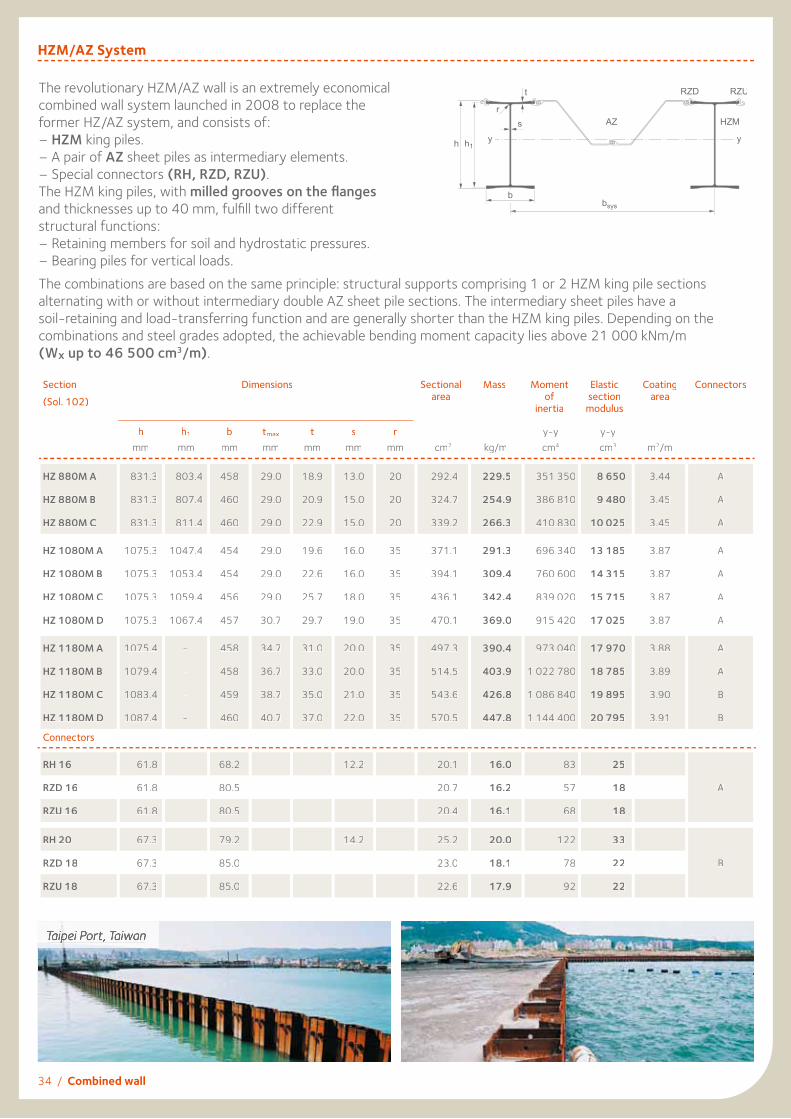
Section(Sol. 102)
Dimensions
Sectionalarea
Mass Moment of
inertia
Elasticsection
modulus
Coatingarea
Connectors
hmm
h1
mmb
mmtmax
mmt
mms
mmr
mm cm2 kg/m y-y cm4
y-y cm3 m2/m
HZ 880M A 831.3 803.4 458 29.0 18.9 13.0 20 292.4 229.5 351 350 8 650 3.44 A
HZ 880M B 831.3 807.4 460 29.0 20.9 15.0 20 324.7 254.9 386 810 9 480 3.45 A
HZ 880M C 831.3 811.4 460 29.0 22.9 15.0 20 339.2 266.3 410 830 10 025 3.45 A
HZ 1080M A 1075.3 1047.4 454 29.0 19.6 16.0 35 371.1 291.3 696 340 13 185 3.87 A
HZ 1080M B 1075.3 1053.4 454 29.0 22.6 16.0 35 394.1 309.4 760 600 14 315 3.87 A
HZ 1080M C 1075.3 1059.4 456 29.0 25.7 18.0 35 436.1 342.4 839 020 15 715 3.87 A
HZ 1080M D 1075.3 1067.4 457 30.7 29.7 19.0 35 470.1 369.0 915 420 17 025 3.87 A
HZ 1180M A 1075.4 - 458 34.7 31.0 20.0 35 497.3 390.4 973 040 17 970 3.88 A
HZ 1180M B 1079.4 - 458 36.7 33.0 20.0 35 514.5 403.9 1 022 780 18 785 3.89 A
HZ 1180M C 1083.4 - 459 38.7 35.0 21.0 35 543.6 426.8 1 086 840 19 895 3.90 B
HZ 1180M D 1087.4 - 460 40.7 37.0 22.0 35 570.5 447.8 1 144 400 20 795 3.91 B
Connectors
RH 16 61.8 68.2 12.2 20.1 16.0 83 25
RZD 16 61.8 80.5 20.7 16.2 57 18 A
RZU 16 61.8 80.5 20.4 16.1 68 18
RH 20 67.3 79.2 14.2 25.2 20.0 122 33
RZD 18 67.3 85.0 23.0 18.1 78 22 B
RZU 18 67.3 85.0 22.6 17.9 92 22
HZM/AZ System
The revolutionary HZM/AZ wall is an extremely economical combined wall system launched in 2008 to replace the former HZ/AZ system, and consists of:– HZM king piles.– A pair of AZ sheet piles as intermediary elements.– Special connectors (RH, RZD, RZU).The HZM king piles, with milled grooves on the fl anges and thicknesses up to 40 mm, fulfi ll two different structural functions:– Retaining members for soil and hydrostatic pressures.– Bearing piles for vertical loads.The combinations are based on the same principle: structural supports comprising 1 or 2 HZM king pile sections alternating with or without intermediary double AZ sheet pile sections. The intermediary sheet piles have a soil-retaining and load-transferring function and are generally shorter than the HZM king piles. Depending on the combinations and steel grades adopted, the achievable bending moment capacity lies above 21 000 kNm/m (Wx up to 46 500 cm3/m).
Taipei Port, Taiwan

Combined wall / 35
The outstanding feature of the HZM/AZ combined wall system is the extensive range of possible combinations using the entire AZ sheet pile offer, including the latest wide AZ-700 range, as well as all rolled-up and rolled-down AZ sections. The table below contains but a small sample of the available systems. Please refer to our brochure “The HZM Steel Wall System” for detailed information on the entire HZM/AZ range.
Section Sectionalarea
cm2/m
Moment ofinertia
cm4/m
Elastic1)
sectionmodulus
cm3/m
Elastic2)
sectionmodulus
cm3/m
Mass3)
Coatingarea4)
Water sidem2/m
Mass100
kg/m2
Mass60
kg/m2
Combination HZM ...- 12 / AZ 18-700 HZ 880M A 274.1 240 500 5 380 6 160 215 177 2.48
HZ 880M B 290.5 259 000 5 820 6 560 228 190 2.48
HZ 880M C 298.0 271 570 6 100 6 850 234 196 2.48
HZ 1080M A 315.5 443 030 7 745 8 690 248 209 2.47
HZ 1080M B 327.5 476 790 8 340 9 295 257 219 2.47
HZ 1080M C 349.0 517 420 9 065 10 010 274 235 2.48
HZ 1080M D 366.4 557 070 9 735 10 720 288 249 2.48
bsys = 1.927 m HZ 1180M A 380.4 586 870 10 220 11 255 299 260 2.48
HZ 1180M B 389.3 613 030 10 680 11 705 306 267 2.48
HZ 1180M C 406.5 651 410 11 275 12 410 319 280 2.49
HZ 1180M D 420.2 681 600 11 830 12 895 330 291 2.50
Combination HZM ...- 24 / AZ 18-700 HZ 880M A 356.1 363 720 8 525 7 885 280 249 3.00
HZ 880M B 382.2 392 360 9 200 8 550 300 269 3.01
HZ 880M C 394.2 412 400 9 645 9 005 309 279 3.01
HZ 1080M A 423.2 688 290 12 515 11 775 332 301 2.99
HZ 1080M B 442.1 741 310 13 440 12 715 347 316 2.99
HZ 1080M C 476.4 805 720 14 585 13 870 374 343 3.00
HZ 1080M D 504.4 868 900 15 660 15 000 396 365 3.00
bsys = 2.398 m HZ 1180M A 526.6 916 220 16 425 15 845 413 383 3.00
HZ 1180M B 540.0 955 000 17 075 16 535 424 393 3.00
HZ 1180M C 569.5 1 022 790 18 200 17 595 447 416 3.02
HZ 1180M D 589.3 1 064 090 18 895 18 330 463 431 3.03
Denomination of the HZM/AZ system:
1) Referring outside of HZM-fl ange. 2) Referring outside of RH / RZ.3) LRH = LHZM; LRZU = LRZD = LAZ ; Mass100: LAZ = 100 % LHZM; Mass60: LAZ = 60 % LHZM 4) Excluding inside of interlocks, per system width.
HZ 880M A -
King pile
2 connectors1 RZD + 1RZU
1 2 / AZ 18 - 700
1 king pileHZ 880M A
Intermediary AZ 18-700 double pile
CT, JadeWeserPort, Germany

36 / Combined wall
Combined wall with tubular piles
Combined wall system tube - AZ
In cooperation with ArcelorMittal Projects, ArcelorMittal Commercial RPS supplies spirally welded tubular piles from its mill in Dintelmond delivered with EN 10204 - 2004 certifi cation. Equipped with a deep-water quay, the Dutch mill can export tubular foundation piles with diameters up to 3000 mm, wall thicknesses up to 25 mm, and lengths up to 49 m without butt-welding. Tubular piles are available in numerous European and US steel grades due to ArcelorMittal’s worldwide network of coil producers. The piles can be coated on request and provided with
welded pile interlocks or C6 or C9 connectors. Tubular piles are the main retaining elements of the combined wall, carrying horizontal loads from soil and water pressures and vertical foundation loads. The intermediary sheet piles (preferably Z-shaped) transfer horizontal loads to the tubular piles. The table below gives an overview of some of the possible combined wall systems. The table is valid for C9 connectors. Please refer to our brochure “Spirally welded steel pipes” for further details.
b sys
Connectors AZ sheet pile
Tubularpile D
t
1) Mass60: Lconn. = LAZ = 60% LTube2) Mass100: Lconn. = LAZ = 100% LTube
Tubular pile System with infi ll sheet pile AZ 18-700 double pile
Diameter D mm
Thickness t mm
bsys m
Mass601)
kg/m2
Mass1002)
kg/m2
Isys cm4/m
Wsys cm3/m
1626 18 3.09 265 287 969630 11925
1626 20 3.09 290 312 1071540 13180
1626 22 3.09 315 338 1172690 14425
1829 18 3.29 276 297 1292740 14135
1829 20 3.29 303 323 1429920 15635
1829 22 3.29 329 350 1566190 17125
2032 20 3.49 314 333 1847240 18180
2032 22 3.49 342 361 2024480 19925
2032 24 3.49 370 389 2200660 21660
2540 21 4.00 352 369 3308840 26055
2540 23 4.00 383 400 3614160 28460
2540 25 4.00 413 431 3918020 30850
2997 21 4.46 369 384 4888930 32625
2997 23 4.46 402 417 5342700 35655
2997 25 4.46 434 450 5794630 38670

Combined wall / 37
Lock, Evergem, Belgium
Cruise terminal, Kiel, Germany
Wharf renovation, Miami, USA
The section modulus Wsys and the moment of inertia Isys of the combined wall are given as follows:
with
AZ sheet piles in combined walls have the following advantages:
– Better load-displacement behaviour and reduced deformation compared to double or triple U-piles.
– Soil and water pressures are optimally transferred to the tubular pile as normal tensile stresses. Due to the membrane effect, AZ intermediary sheet piles are particularly suitable for transmitting very high loads.
– AZ intermediary sheet piles are less affected by driving inaccuracies due to their geometry.
– Larssen-type interlocks contribute to the high performance of AZ intermediary sheet piles.
Tubular piles and intermediary AZ sheet piles are attached together with connectors welded onto the tubular piles. The C9 connectors have a fi xed interlock opening and therefore guide the AZ pile into its optimal position during driving. Tubular king piles with connectors are driven fi rst, AZ sheet piles are then installed in the gaps between the king piles. Please refer to our brochure “AZ sheet piles in combined walls” for further details.
I sys =I king pile + I ssp
b sys
Wsys =10 · I sys
D/2
I king pile =π · D4- (D-2t)4
6.4 · 105·
I sys [cm4/m]: Moment of inertia of combined wallWsys [cm3/m]: Section modulus of combined wallI king pile [cm4]: Moment of inertia of tubular king pileI ssp [cm4]: Moment of inertia of intermediary sheet pilebsys [m]: System widthD [mm]: Outside diameter of tubular pilet [mm]: Thickness of tubular pile
Connector
Weld
Tubular king pile

Sheet pile sections and corresponding driving caps
Single and box piles can be driven to the top of the neighbouring pile when using UD driving caps.
For other driving elements (HZM, built-up box piles, triple piles, etc.) please contact our Technical Department.
Driving capsA driving cap is a very important accessory, providing good energy transfer between the hammer and the sheet pile section, thus preventing damage to the pile. Impact hammers, especially diesel hammers, need a special driving cap. It is generally made of cast steel, with an arrangement of guiding grooves for the different sheet pile sections on its lower side. A dolly is fi tted into a recess on the top of the driving cap. Dollies are normally made of wooden or plastic components or a combination of several different elements. Each driving cap generally fi ts several sheet pile sections, thus reducing the number of required driving caps for a given sheet pile range.
Section Arrangement Driving caps
AU 14/16/18/20/23/25 single AUS 14-26
AU 14/16 double/box pile AUD 12-16
AU 18/20/23/25 double/box pile AUD 20-32
PU 12/18/22/28/32, GU 18N single PUS
PU 12/28/32 single US-B
PU 12 double/triple/box pile UD 1
PU 18/22/32, GU 18N double/triple/box pile UD 2
PU 18/22/28/32, GU 18N double/box pile PUD 17-33
AZ 12-770 to AZ 14-770-10/10, AZ 12-700 to AZ 14-700 double AZD 12-14 L
AZ 17-700 to AZ 20-700/AZ 24-700 to AZ 28-700 double UZD 14-28
AZ 36-700N to AZ 46-700N double AZD 36-40
AZ 18/26 double A 18/26
AZ 46/48/50 double A 48
Driving cap dimensions
Driving caps AUS 14-26 AUD 12-16 AUD 20-32 PUS US-B UD 1 UD 2
A/B/H 740/580/370 1540/750/520 1570/750/520 680/600/320 680/600/320 1250/610/420 1250/720/420
C 350 430 430 290 290 260 315
Mass [kg] 650 1900 2100 300 300 1000 1250
a/b (or Ø) / h1) 500/300/120 600/400/170 600/400/170 380/380/120 380/380/120 Ø400/170 Ø500/170
Driving caps PUD 17-33 A 18/26 A 48 AZD 12-14 L UZD 14-28 AZD 36-40
A/B/H 1250/720/420 1160/660/420 1080/730/470 1440/590/520 1300/705/520 1320/750/520
C 315 390 430 360 420 440
Mass [kg] 1150 1150 1400 1750 1900 2050
a/b (or Ø) / h1) Ø500/170 600/400/170 600/400/170 600/300/170 600/400/170 600/400/170
1) Dimensions of the dolly recess.
38 / Driving caps

Driving caps - Examples
Arrangement of driving caps
Sliding guides
Sliding guides are designed to guide the driving cap along the lead, thus guaranteeing proper alignment of the
hammer and the centre of the driving cap. Their adaptation to the leader is normally carried out in situ.
Dimensions Designation Corresponding driving caps
330/50 PUS and US-B
30 UD
500/90 A and AUS
700/90 AUD and AZD
b
a
c
e
d
a
d
e
b
ca = dolly/cushionb = leaderc = sliding guided = driving cape = leader slide
The leader slide is not provided by ArcelorMittal.
5042
0
300
H =
520 h
= 17
0h
= 17
050
Section 1-1 (UZD 14-28)Dolly (Cushion)Type: C600x400x220Type: C600x400x220T
mmType: C600x400x220Type: C600x400x220T
A =A =A 1300
a = 600
790
b =
400
b =
400
b =
400
575
C =
420
90
B =
705
UZD
14-
28U
ZD 1
4-28
1
1
Plan view
GuidanceType: 700/90Type: 700/90T
mm Dolly (Cushion) Bottom view
Position of section AZ 17-700 .... AZ 28-700as double and single pile
5042
0
300
50
Section 1-1 (AUD 20-32)Dolly (Cushion)Type: C600x400x220Type: C600x400x220T
H =
520 h
= 17
0
mm Dolly (Cushion)Type: C600x400x220Type: C600x400x220T
GuidanceType: 700/90Type: 700/90T
B =
750
630
A =1570A =1570A
790
a = 600a = 600
b =
400
b =
400
AU
D 2
0-32
AU
D 2
0-32
C =
430
90
1
1
Plan view mm Bottom view
Position of section AU 18 / 20 / 23 / 25as double, single and box pile
Driving caps / 39
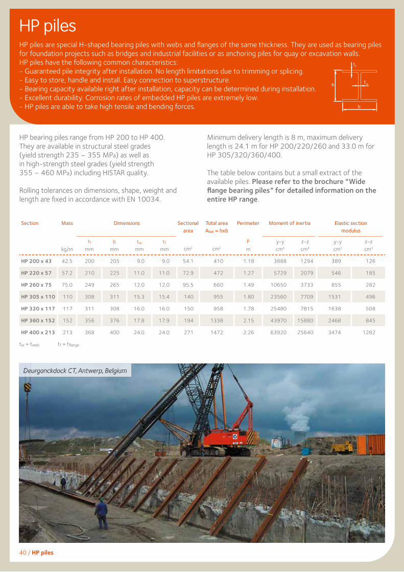
HP bearing piles range from HP 200 to HP 400.They are available in structural steel grades (yield strength 235 – 355 MPa) as well asin high-strength steel grades (yield strength355 – 460 MPa) including HISTAR quality.
Rolling tolerances on dimensions, shape, weight and length are fi xed in accordance with EN 10034.
Minimum delivery length is 8 m, maximum deliverylength is 24.1 m for HP 200/220/260 and 33.0 m forHP 305/320/360/400.
The table below contains but a small extract of the available piles. Please refer to the brochure “Wide fl ange bearing piles” for detailed information on the entire HP range.
HP pilesHP piles are special H-shaped bearing piles with webs and fl anges of the same thickness. They are used as bearing piles for foundation projects such as bridges and industrial facilities or as anchoring piles for quay or excavation walls.HP piles have the following common characteristics:- Guaranteed pile integrity after installation. No length limitations due to trimming or splicing.- Easy to store, handle and install. Easy connection to superstructure.- Bearing capacity available right after installation, capacity can be determined during installation.- Excellent durability. Corrosion rates of embedded HP piles are extremely low.- HP piles are able to take high tensile and bending forces.
Section
Mass
kg/m
Dimensions
Sectionalarea
cm2
Total areaAtot = hxb
cm2
Perimeter
Pm
Moment of inertia
Elastic sectionmodulus
hmm
bmm
twmm
tfmm
HP 200 x 43 42.5 200 205 9.0 9.0 54.1 410 1.18 3888 1294 389 126
HP 220 x 57 57.2 210 225 11.0 11.0 72.9 472 1.27 5729 2079 546 185
HP 260 x 75 75.0 249 265 12.0 12.0 95.5 660 1.49 10650 3733 855 282
HP 305 x 110 110 308 311 15.3 15.4 140 955 1.80 23560 7709 1531 496
HP 320 x 117 117 311 308 16.0 16.0 150 958 1.78 25480 7815 1638 508
HP 360 x 152 152 356 376 17.8 17.9 194 1338 2.15 43970 15880 2468 845
HP 400 x 213 213 368 400 24.0 24.0 271 1472 2.26 63920 25640 3474 1282
Deurganckdock CT, Antwerp, Belgium
b
h
t f
t w
y-ycm4
y-ycm3
z-zcm4
z-zcm3
tw = tweb tf = tfl ange
40 / HP piles

Corrosion rates
Durability of steel sheet piles
Unprotected steel in the atmosphere, water or soil is subject to corrosion that may lead to damage. Local weakening and rusting-through are normally considered to be maintenance problems that can be remedied locally.Depending on life-time requirements and accessibility of the structure, the service life of a steel structure can be achieved by one or a combination of following methods:– protection by coating
(typically only in high corrosion zones),– use of a stronger section or a higher steel grade to
create a ‘statical reserve’,
– use of Marine Grade Steel ASTM A690 (splash zone),– avoiding important bending moments in the high
corrosion zones,– extension of the concrete capping beam below the
low-water level,– cathodic protection by impressed current or by
sacrificial anodes (protects the surface constantly in contact with water),
– use of AMLoCor steel grade (permanent immersion zone and low water zone).
The maximum steel stress in most maritime sheet pile structures is situated within the permanent immersion zone. The loss of thickness in this zone is considerably lower than in the high corrosion zones. Steel stress is generally very low in the maximum corrosion zones: splash zone & low water zone. These locations are therefore not the critical part of the structure despite their negative appearance if unprotected.
Typical loss of thickness due to corrosion and moment distribution for anchored sheet pile wall in marine environment:
The use of a new steel grade AMLoCor significantly increases the design life of marine structures.Please refer to EC 3 Part 5 (EN 1993-5) for details on loss of steel thickness as a result of exposure in different media.
Durability / 41
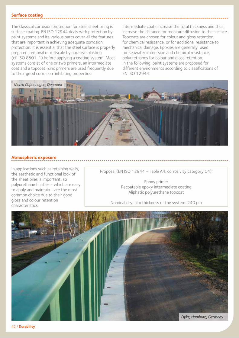
Metro Copenhagen, Denmark
Surface coating
The classical corrosion protection for steel sheet piling is surface coating. EN ISO 12944 deals with protection by paint systems and its various parts cover all the features that are important in achieving adequate corrosion protection. It is essential that the steel surface is properly prepared: removal of millscale by abrasive blasting (cf. ISO 8501-1) before applying a coating system. Most systems consist of one or two primers, an intermediate coat and a topcoat. Zinc primers are used frequently due to their good corrosion-inhibiting properties.
Intermediate coats increase the total thickness and thus increase the distance for moisture diffusion to the surface. Topcoats are chosen for colour and gloss retention, for chemical resistance, or for additional resistance to mechanical damage. Epoxies are generally used for seawater immersion and chemical resistance, polyurethanes for colour and gloss retention. In the following, paint systems are proposed for different environments according to classifi cations of EN ISO 12944.
Atmospheric exposure
In applications such as retaining walls, the aesthetic and functional look of the sheet piles is important, so polyurethane fi nishes - which are easy to apply and maintain - are the most common choice due to their good gloss and colour retention characteristics.
Proposal (EN ISO 12944 – Table A4, corrosivity category C4):
Epoxy primerRecoatable epoxy intermediate coating
Aliphatic polyurethane topcoat
Nominal dry-fi lm thickness of the system: 240 µm
Dyke, Hamburg, Germany
42 / Durability
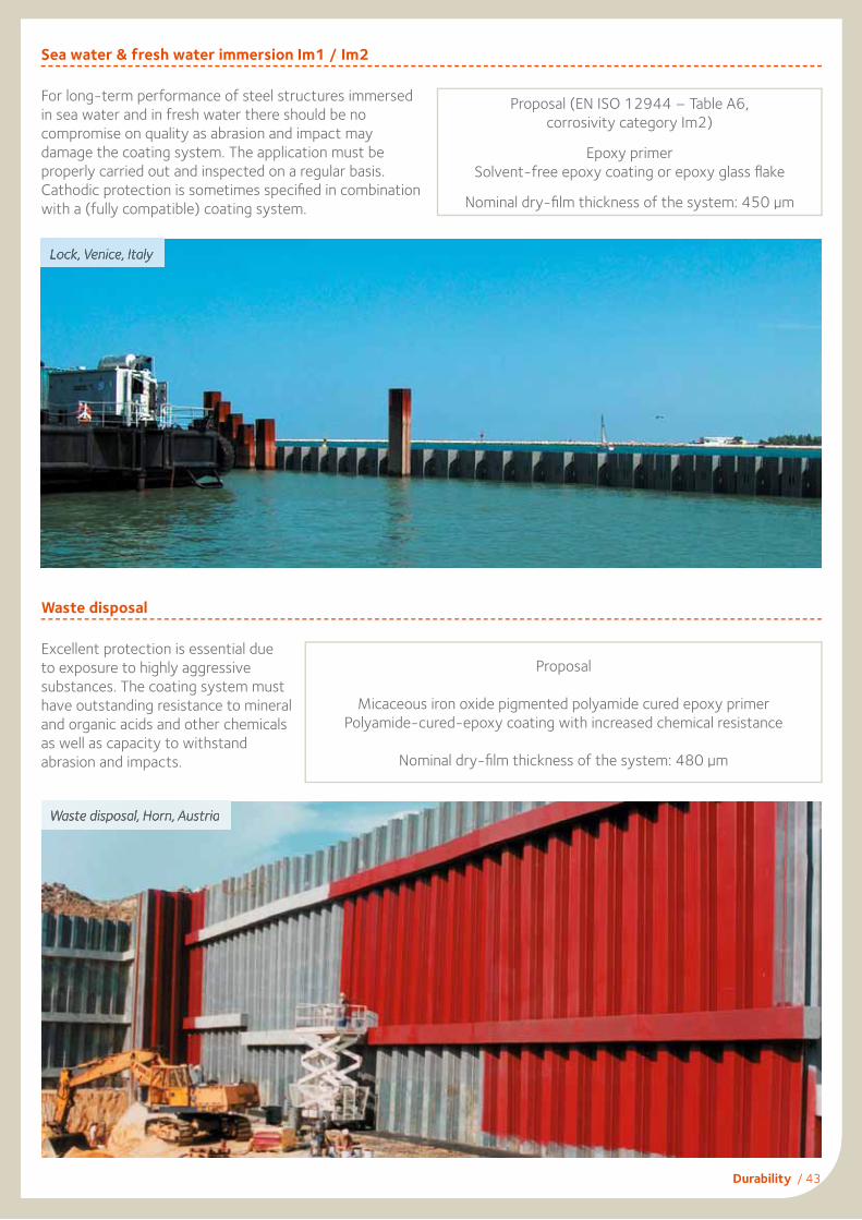
Durability / 43
Lock, Venice, Italy
Sea water & fresh water immersion Im1 / Im2
For long-term performance of steel structures immersedin sea water and in fresh water there should be no compromise on quality as abrasion and impact may damage the coating system. The application must be properly carried out and inspected on a regular basis. Cathodic protection is sometimes specifi ed in combination with a (fully compatible) coating system.
Waste disposal
Excellent protection is essential dueto exposure to highly aggressive substances. The coating system must have outstanding resistance to mineral and organic acids and other chemicals as well as capacity to withstand abrasion and impacts.
Proposal (EN ISO 12944 – Table A6,corrosivity category Im2)
Epoxy primerSolvent-free epoxy coating or epoxy glass fl ake
Nominal dry-fi lm thickness of the system: 450 µm
Waste disposal, Horn, Austria
Proposal
Micaceous iron oxide pigmented polyamide cured epoxy primerPolyamide-cured-epoxy coating with increased chemical resistance
Nominal dry-fi lm thickness of the system: 480 µm

AMLoCorTM
New corrosion resistant steel grade for marine applications
44 / AMLoCor™
AMLoCor™ is ArcelorMittal’s new ‘low corrosion’ steel grade that will revolutionize the design of port structures in the future.
The key advantage of AMLoCor is a signifi cant reduction of the corrosion rates in the ‘Low Water Zone’ (LWZ) and in the ‘Permanent Immersion Zone’ (PIZ), which is normally the location of the maximum bending moments, and consequently highest steel stresses. This new steel grade is the solution from our R&D department to address the major concern of designers and port authorities: durability of marine structures like quay walls, breakwaters, jetties.
Eurocode 3 Part 5 contains reference tables with typical corrosion rates valid for standard carbon steel in northern European countries. In-situ tests have proven that the loss of steel thickness of AMLoCor is reduced by a factor 3 (PIZ) to 5 (LWZ) compared to standard structural steel in the critical zones.
AMLoCor leads to considerable savings in steel weight compared to the unprotected carbon steel piling solution, as soon as loss of steel thickness due to corrosion in the immersion zone is signifi cant. Cathodic protection or coatings can be used to increase the service life of the sheet pile structure. However, AMLoCor will in many cases yield the most cost-effective solution in the long-term. AMLoCor is compatible with cathodic protection and coatings.
In addition AMLoCor protects steel from “ALWC” (Accelerated Low Water Corrosion) which is related to biological activity enhancing degradation of steel in the low water zone.
The mechanical properties of AMLoCor steel are fully equivalent to standard piling grades, so that structural resistance can be determined according to all relevant design codes used for steel sheet piling structures, like EN 1993-5:2007 in European countries.
Some AZ sections are already available in AMLoCor steel grades, ranging from AMLoCor Blue 320 to Blue 390 (yield strength 320 MPa up to 390 MPa). Please check our website for regular updates on available sections.
A driving test was performed in very compact soil in Denmark. Sheet piles in S 355 GP and AMLoCor Blue 355 were driven into very hard soils with some boulders. The sheet piles were monitored during driving, then pulled out and inspected. This test has demonstrated that the behaviour of AMLoCor sheet piles is as good as regular carbon steel sheet piles.
For more detailed information (e.g. on welding) please check our new brochure ‘AMLoCor’, part 1 to 3.
Zone of high attack
Zone of high attack
Permanentimmersion zone
Waterside Earthside
MHW
MLW
Anchor
Loss
of t
hick
ness
Bend
ing
Mom
ent
Atmospheric zone
Intertidal zone
Low water zone
Splash zone
Mmax.
Carbon SteelAMLoCor
MHW
MLW
0
2
4
6
8
10
12
14
0.00 0.05 0.10 0.15 0.20 0.25
Corrosion rate (mm/year)
Dis
tanc
e fr
om to
p of
she
et p
iling
wal
l (m
)
Atmospheric
Splash
Tidal
Low water
Permanentimmersion
MHW
MLW
Carbon Steel AMLoCor
Typical loss of steel thickness in a marine environment: regular carbon steel vs. AMLoCor
Strain (%)
Stre
ss (M
Pa)
00
Carbon SteelAMLoCor
Typical Stress – Strain diagram of carbon steel & AMLoCor
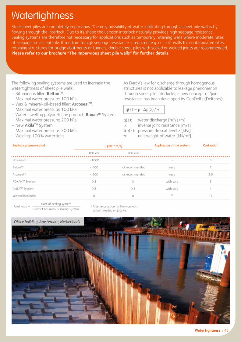
WatertightnessSteel sheet piles are completely impervious. The only possibility of water infi ltrating through a sheet pile wall is by fl owing through the interlock. Due to its shape the Larssen interlock naturally provides high seepage resistance. Sealing systems are therefore not necessary for applications such as temporary retaining walls where moderate rates of seepage are acceptable. If medium to high seepage resistance is required, e.g. cut-off walls for contaminated sites, retaining structures for bridge abutments or tunnels, double sheet piles with sealed or welded joints are recommended. Please refer to our brochure “The impervious sheet pile walls” for further details.
Offi ce building, Amsterdam, Netherlands
Sealing system/method ρ [10-10 m/s] Application of the system Cost ratio1)
100 kPa 200 kPa
No sealant > 1000 - - 0
BeltanTM < 600 not recommended easy 1
ArcosealTM < 600 not recommended easy 2.5
ROXANTM System 0.3 3 with care 5
AKILATM System 0.3 0.3 with care 4
Welded interlocks 0 0 2) 15
1) Cost ratio =Cost of sealing system
Cost of bituminous sealing system2) After excavation for the interlock
to be threaded on jobsite.
The following sealing systems are used to increase the watertightness of sheet pile walls:– Bituminous fi ller: BeltanTM.
Maximal water pressure: 100 kPa.– Wax & mineral-oil-based fi ller: ArcosealTM.
Maximal water pressure: 100 kPa.– Water-swelling polyurethane product: RoxanTM System.
Maximal water pressure: 200 kPa.– New AkilaTM System.
Maximal water pressure: 300 kPa.– Welding: 100% watertight.
As Darcy’s law for discharge through homogenous structures is not applicable to leakage phenomenon through sheet pile interlocks, a new concept of ‘joint resistance’ has been developed by GeoDelft (Deltares).
q(z) = ρ • ∆p(z)/γ
q(z): water discharge [m3/s/m]ρ: inverse joint resistance [m/s]∆p(z): pressure drop at level z [kPa]γ: unit weight of water [kN/m3]
Watertightness / 45

A series of in-situ tests were carried out in stiff clays and in soft sandy soils. Single and crimped double sheet piles fi tted out with the AKILA™ system were driven into the ground using an impact hammer as well as a vibratory hammer.
In case of vibrodriving, sheet piles were driven continuously at a minimum rate of 20 seconds per meter. After installation, watertightness was tested at water pressures of 2 and 3 bar, according to a procedure developed by Delft Geotechnics (Deltares) and ArcelorMittal. The testing and the results were witnessed and certifi ed by ‘Germanischer Lloyd’, an independent third party.
The average inverse joint resistance ρm was determined according to EN 12063.
For more information contact our technical department.
46 / AKILA™
AKILATM. New sealing system
Inverse joint resistance ρm
AKILA™ is a brand new environmentally friendly high performance sealing system for ArcelorMittal steel sheet piles. The system is based on three sealing ‘lips’ mechanically extruded into the free interlocks using a product called MSP-1. The common interlock of double piles is sealed with a second product called MSP-2.
MSP-1 and MSP-2 belong to the family of silane modifi ed polymers (MS-Polymers). Both products resist to humidity and weathering. Their main characteristics are:
– single component elastic sealants with a density of • 1.41 g/cm3 for MSP-1 • 1.48 g/cm3 for MSP-2– UV-stable– excellent adhesion to steel– resist to temperatures between -40°C and +90°C
(up to 120°C for short periods)– elongation at break > 380%– Shore A hardness after complete polymerization • 58 for MSP-1 • 44 for MSP-2 (after 14 days)– durable in contact with freshwater, seawater, as well as
various hydrocarbons, bases and acids (depending on concentration – a complete list is available on request).
MS-Polymers are solvent free and do not contain isocyanates. They can be considered as environmentally friendly products. AKILA™ is certifi ed by the ‘Hygiene-Institut des Ruhrgebiets’ in Germany as suitable for use in contact with groundwater.The interlocks of the free interlocks have to be chamfered at the top (see sketch). Penetration of soil into the inter-locks during driving should be prevented, for instance by inserting a bolt at the bottom of the interlock (bolt tack welded). The ambient temperature during installation must be above 0°C. Additionally, to improve the sliding of the interlocks, an environmentally friendly lubricant must be applied to the sealant in the interlocks prior to driving. The layout and driving direction of the sheet pile wall shall be determined before ordering the sheet piles (delivery form of double piles, chamfering of interlocks, etc).
ρm (m/s)
water pressure 200 kPa 300 kPa
single piles (MSP-1) 4.9 x 10⁻¹¹ 8.6 x 10⁻¹¹
double piles (MSP-1 & MSP-2) 3.3 x 10⁻¹¹ 4.7 x 10⁻¹¹
Sketch of MSP-1 product extruded into the free interlock
Installation recommendations (driving direction, chamfer, etc)
Chamfer
Driving direction
AKILA™& Lubricant
Chamfer
Bolt
Bolt

Environment has become a major focus in the construction industry. Public authorities and private investors are seeking more environmentally-friendly construction methods and products. Environmental factors already infl uence the choice of the construction solution in some countries. The results of a LCA are related to a feature representative of the product and the service being expected from it. The functional unit is used to describe the primary functions to be fulfi lled by a product system. When comparing several products, it is necessary to consider an identical functional unit for both products. The major benefi t of steel sheet piles versus alternative solutions is the fact that besides being 100% recyclable, steel sheet piles can be reused multiple times, hence decreasing its environmental burden.
LCA practitioners usually assess some common environmental indicators. Generally, several substances contribute to a given environmental impact. For example, carbon dioxide (CO2), methane (CH4), nitrous oxide (N2O) and some other components all contribute to greenhouse gases emissions, respectively with different weights according to academic models, and the resulting impact is expressed as “CO2 equivalent” emissions because CO2 is the major contributor. This is a way to illustrate one simple aggregated value for the impact. The main environmental indicators are:• Primary Energy Consumption (MJ) • Global Warming Potential (CO2-equivalent)• Acidifi cation (acidifi cation of rain, SO2-eq)• Ozone formation at low altitude (summer smog, C2H4–eq)• Eutrophication (PO4–eq)• Water (kg of water used).
The functional unit selected is a 100 m retaining wall structure. Results are aggregated as the sum of the impacts of the production and end of life stage. During the use phase, impacts are negligible. Certifi ed data used for the environmental profi le calculations of the steel structure comes from the “World Steel Association“ and it represents European average values for “sections” and World average values for “rebars”. They are dated from 2010. According to the LCA approach, all elements such as transportation, as well as installation and extraction of the sheet piles are taken into account. Usually wall and wailing parts are recovered and therefore recycled. The distribution of impacts is equivalent for all indicators: steel production is the main contributor (between 93% to 98% of the impacts).
Environmental product declaration / 47
Environmental indicators
Environmental profi le of steel sheet piles
Environmental product declarationArcelorMittal is the fi rst steel manufacturer in the world that has performed a Life Cycle Assessment (LCA) study dedicated to steel sheet pilesi, which has been peer reviewed to be in compliance with the ISO standards 14 040 and 14 044.
For detailed information, please consult our brochure ”Environmental product declaration for Steel Sheet Piling structures”.
i Hettinger, A.L.; Bourdouxhe, M.P.; Schmitt, A. “Comparative Environmental evaluation of retaining structures made of steel sheet piling or reinforced concrete”. ArcelorMittal, 2010.
Environmental burdens of steel productsused for sheet piling structures
The offi cial World Steel Association formula used to calculate the environmental burden E is:
E = E’ - (RR - RC) • LCIscrap and LCIscrap = y • (Xpr - Xre)
With:
E‘ “cradle to gate” environmental burden due to the production phase
RR Recycling Rate at the end of lifeRC Recycled Content = amount of scrap used to produce
steelLCIscrap represents the environmental value of scrap
(environmental burden avoided by using scrap as raw material)
y effi ciency of the electrical arc furnace in converting scrap into steel
Xpr LCI for primary steel production (BOF: 100% iron ore)Xre LCI for secondary steel production (EAF: 100% scrap)This formula allows taking into account the benefi t of the end of life recycling, penalizing steel if the recycling rate is lower than the recycled content. Two LCI among the 16 life cycle inventories (LCI) of steel products provided by World Steel Association were used for this LCA.

48 / Delivery conditions
Tolerances on shape and dimensions of hot rolled steel sheet piles according to EN 10248(reduced tolerances on request)
Tolerances AU, PU, GU AZ AS 500 HZM
Mass1) ± 5% ± 5% ± 5% ±5 %
Length (L) ± 200 mm ± 200 mm ± 200 mm ± 200 mm
Height (h)2) h ≤ 200 mm: ± 4 mmh > 200 mm: ± 5 mm
h ≥ 300 mm: ± 7 mm - h ≥ 500 mm: ± 7 mm
Thicknesses (t,s)t, s ≤ 8.5 mm: ± 0.5 mm
t, s > 8.5 mm: ± 6% t, s ≤ 8.5 mm: ± 0.5 mm
t, s > 8.5 mm: ± 6% t > 8.5 mm: ± 6%
t, s ≤ 12.5 mm: –1.0 mm / +2.0 mmt, s > 12.5 mm: –1.5 mm / +2.5 mm
Width single pile (b) ± 2% b ± 2% b ± 2% b ± 2% b
Width double pile (2b) ± 3% (2b) ± 3% (2b) ± 3% (2b) ± 3% (2b)
Straightness (q) ≤ 0.2% L ≤ 0.2% L ≤ 0.2% L ≤ 0.2% L
Ends out of square ± 2% b ± 2% b ± 2% b ± 2% b
Maximum rolling lengths (longer sections available on request)
Section AZ AU, PU GU sp1) GU dp1) AS 500 HZM RH / RZ OMEGA 18 C9 / C14 DELTA 13
Length [m] 31 31 24 22 31 33 24 16 18 171) sp = single pile, dp = double pile. Contact us for more details.
Handling holes
Sheet pile sections are normally supplied without handling holes. If requested, they can be provided with handling holes in the centerline of the section. The standard handling hole dimensions are as follows:
Markings
The following markings can be supplied on request:– Colour marks defi ning section, length and steel grade.– Adhesive stickers showing the customer’s name, destination,
order number, type and length of profi le and steel grade.
Y
Z-Section U-Section Straight Web Section HZM-Section
Diameter D [mm] 40 40 50 50 63.5 40
Distance Y [mm] 75 300 200 250 230 150
Diameter D [in] 2.5
Distance Y [in] 9
Delivery conditions
1) From the mass of the total delivery. 2) Of single pile.
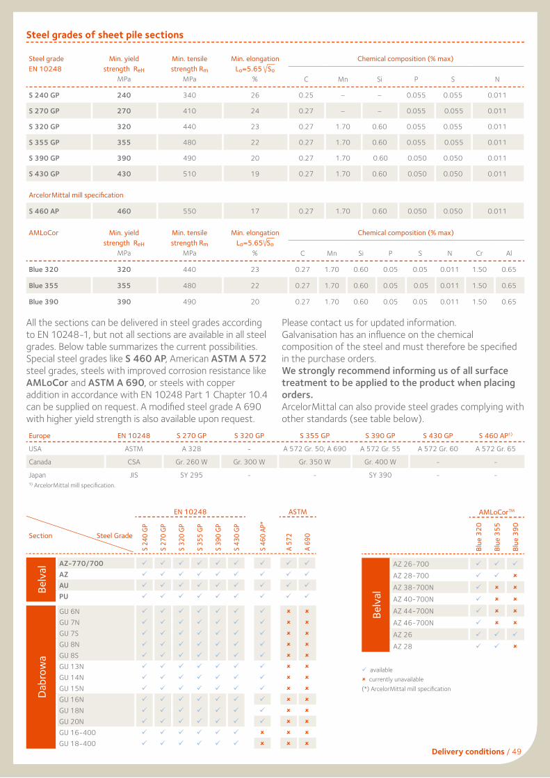
Delivery conditions / 49
Steel grades of sheet pile sections
Steel gradeEN 10248
Min. yield strength ReH
MPa
Min. tensile strength Rm
MPa
Min. elongationLo=5.65 So
%
Chemical composition (% max)
C Mn Si P S N
S 240 GP 240 340 26 0.25 – – 0.055 0.055 0.011
S 270 GP 270 410 24 0.27 – – 0.055 0.055 0.011
S 320 GP 320 440 23 0.27 1.70 0.60 0.055 0.055 0.011
S 355 GP 355 480 22 0.27 1.70 0.60 0.055 0.055 0.011
S 390 GP 390 490 20 0.27 1.70 0.60 0.050 0.050 0.011
S 430 GP 430 510 19 0.27 1.70 0.60 0.050 0.050 0.011
ArcelorMittal mill specifi cation
S 460 AP 460 550 17 0.27 1.70 0.60 0.050 0.050 0.011
All the sections can be delivered in steel grades according to EN 10248-1, but not all sections are available in all steel grades. Below table summarizes the current possibilities.Special steel grades like S 460 AP, American ASTM A 572 steel grades, steels with improved corrosion resistance like AMLoCor and ASTM A 690, or steels with copper addition in accordance with EN 10248 Part 1 Chapter 10.4 can be supplied on request. A modifi ed steel grade A 690 with higher yield strength is also available upon request.
Please contact us for updated information.Galvanisation has an infl uence on the chemicalcomposition of the steel and must therefore be specifi edin the purchase orders.We strongly recommend informing us of all surfacetreatment to be applied to the product when placingorders.ArcelorMittal can also provide steel grades complying with other standards (see table below).
Europe EN 10248 S 270 GP S 320 GP S 355 GP S 390 GP S 430 GP S 460 AP1)
USA ASTM A 328 - A 572 Gr. 50; A 690 A 572 Gr. 55 A 572 Gr. 60 A 572 Gr. 65
Canada CSA Gr. 260 W Gr. 300 W Gr. 350 W Gr. 400 W - -
Japan JIS SY 295 - - SY 390 - -1) ArcelorMittal mill specifi cation.
AMLoCor Min. yield strength ReH
MPa
Min. tensile strength Rm
MPa
Min. elongationLo=5.65 So
%
Chemical composition (% max)
C Mn Si P S N Cr Al
Blue 320 320 440 23 0.27 1.70 0.60 0.05 0.05 0.011 1.50 0.65
Blue 355 355 480 22 0.27 1.70 0.60 0.05 0.05 0.011 1.50 0.65
Blue 390 390 490 20 0.27 1.70 0.60 0.05 0.05 0.011 1.50 0.65
EN 10248 ASTM
Section Steel Grade
S 24
0 GP
S 27
0 GP
S 32
0 GP
S 35
5 GP
S 39
0 GP
S 43
0 GP
S 46
0 AP
*
A 57
2
A 69
0
Belv
al
AZ-770/700
AZ
AU
PU
Dab
row
a
GU 6N
GU 7N
GU 7S
GU 8N
GU 8S
GU 13N
GU 14N
GU 15N
GU 16N
GU 18N
GU 20N
GU 16-400
GU 18-400
available currently unavailable(*) ArcelorMittal mill specifi cation
AMLoCorTM
Blue
320
Blue
355
Blue
390
Belv
al
AZ 26-700
AZ 28-700
AZ 38-700N
AZ 40-700N
AZ 44-700N
AZ 46-700N
AZ 26
AZ 28
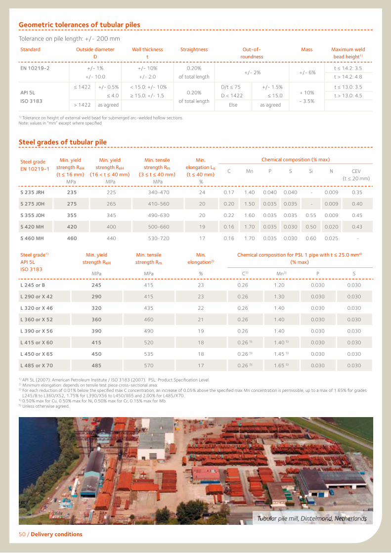
Geometric tolerances of tubular piles
Tubular pile mill, Dintelmond, Netherlands
Standard Outside diameterD
Wall thickness t
Straightness Out-of-roundness
Mass Maximum weldbead height1)
EN 10219-2 +/- 1%+/- 10.0
+/- 10%+/- 2.0
0.20% of total length
+/- 2% +/- 6% t ≤ 14.2: 3.5t > 14.2: 4.8
Steel grades of tubular pile
Steel grade EN 10219-1
Min. yieldstrength ReH(t ≤ 16 mm)
MPa
Min. yield strength ReH
(16 < t ≤ 40 mm) MPa
Min. tensile strength Rm
(3 ≤ t ≤ 40 mm) MPa
Min.elongation Lo(t ≤ 40 mm)
%
Chemical composition (% max)
C Mn P S Si N CEV(t ≤ 20 mm)
S 235 JRH 235 225 340-470 24 0.17 1.40 0.040 0.040 - 0.009 0.35
S 275 J0H 275 265 410-560 20 0.20 1.50 0.035 0.035 - 0.009 0.40
S 355 J0H 355 345 490-630 20 0.22 1.60 0.035 0.035 0.55 0.009 0.45
S 420 MH 420 400 500-660 19 0.16 1.70 0.035 0.030 0.50 0.020 0.43
S 460 MH 460 440 530-720 17 0.16 1.70 0.035 0.030 0.60 0.025 -
Steel grade1)
API 5LISO 3183
Min. yieldstrength ReH
MPa
Min. tensile strength Rm
MPa
Min. elongation2)
%
Chemical composition for PSL 1 pipe with t ≤ 25.0 mm4) (% max)
C3) Mn3) P S
L 245 or B 245 415 23 0.26 1.20 0.030 0.030
L 290 or X 42 290 415 23 0.26 1.30 0.030 0.030
L 320 or X 46 320 435 22 0.26 1.40 0.030 0.030
L 360 or X 52 360 460 21 0.26 1.40 0.030 0.030
L 390 or X 56 390 490 19 0.26 1.40 0.030 0.030
L 415 or X 60 415 520 18 0.26 5) 1.40 5) 0.030 0.030
L 450 or X 65 450 535 18 0.26 5) 1.45 5) 0.030 0.030
L 485 or X 70 485 570 17 0.26 5) 1.65 5) 0.030 0.030
1) API 5L (2007): American Petroleum Institute / ISO 3183 (2007). PSL: Product Specifi cation Level.2) Minimum elongation: depends on tensile test piece cross-sectional area.3) For each reduction of 0.01% below the specifi ed max C concentration, an increase of 0.05% above the specifi ed max Mn concentration is permissible, up to a max of 1.65% for grades
L245/B to L360/X52, 1.75% for L390/X56 to L450/X65 and 2.00% for L485/X70.4) 0.50% max for Cu, 0.50% max for Ni, 0.50% max for Cr, 0.15% max for Mb.5) Unless otherwise agreed.
1) Tolerance on height of external weld bead for submerged arc-welded hollow sections.Note: values in “mm” except where specifi ed
Tolerance on pile length: +/- 200 mm
API 5LISO 3183
≤ 1422 +/- 0.5%≤ 4.0
< 15.0:≥ 15.0:
+/- 10%+/- 1.5 0.20%
of total length
D/t ≤ 75D < 1422
+/- 1.5%≤ 15.0 + 10%
- 3.5%
t ≤ 13.0: 3.5t > 13.0: 4.5
> 1422 as agreed Else as agreed
50 / Delivery conditions

Documentation / 51
The HZM Steel Wall SystemRef. 1-21-11-1
GB, DE, FR, US, IT, SP, PT
AS 500 Straight web steel sheet piles. Design and Execution.
Ref. 1-31-09-1-GB
Spirally welded steel pipesRef. 5-15-08-1
GB
HP bearing pilesRef. 7-1-05-1GB, DE, FR, SP
Cold formed steel pilesRef. 1-6-07-1GB, DE, FR, NL
Harbour constructionRef. 4-2-07-2
GB
Underground car parksRef. 4-13-08-1
GB, PT
Underground car parks – fi re resistanceRef. 3-21-06-1
GB, DE, FR
High speed line south – NLRef. 4-19-07-1
GB, FR, NL
Environmental Product Declaration
Ref. 01-2011 / EPD 00 / 1GB
Installation of sheet pilesRef. 2-21-06
GB, DE, FR
Jetting-assisted sheet pile drivingRef. 2-22-06-1
GB, DE, FR
Anchoring of sheet pilesRef. 2-51-03-1
GB, DE
Off-centre anchoringRef. 2-52-05-1
GB, DE, FR
Impervious steel sheet pile wallsRef. 2-1-08-1
GB, DE, FR
Piling handbookGB
(Electronic fi le only)
Declutching detectorRef. 2-5-05-1
GB, DE, FR
AMLoCor Steel GradeRef. 10.2011 / AMLoCor 1A
GB, DE, RU
AZ sheet piles in combined wallsRef. 5-1-01-1
GB, DE, FR
Waste disposalRef. 4-32-05-1
GB, DE, FR
DocumentationPlease refer to our website to download all our documentation: www.arcelormittal.com/sheetpilingor contact us via E-mail: [email protected]
ArcelorMittal Commercial RPS S.à r.l.Sheet Piling
66, rue de LuxembourgL-4221 Esch-sur-Alzette (Luxembourg)
T (+352) 5313 3105F (+352) 5313 3290E [email protected]/sheetpiling
1-1-
12-2
-GB