steel wire rope slings – safety – part 2: specification ... · en 13414-2:2003+a2 october 2008...
TRANSCRIPT

February 2009DEUTSCHE NORM
English price group 13No part of this standard may be reproduced without prior permission ofDIN Deutsches Institut für Normung e. V., Berlin. Beuth Verlag GmbH, 10772 Berlin, Germany,has the exclusive right of sale for German Standards (DIN-Normen).
ICS 53.020.30
!$UkW"1507252
www.din.de
DDIN EN 13414-2
Steel wire rope slings –Safety –
Part 2: Specification for information for use and maintenance to be
provided by the manufacturer (includes Amendment A2:2008)
English version of DIN EN 13414-2:2009-02
Anschlagseile aus Stahldrahtseilen –Sicherheit –Teil 2: Vom Hersteller zu liefernde Informationen für Gebrauch und Instandhaltung(enthält Änderung A2:2008)Englische Fassung DIN EN 13414-2:2009-02
©
SupersedesDIN EN 13414-2:2003-12 andDIN EN 13414-2/A1:2005-12
www.beuth.de
Document comprises 25 pages
Copyright Deutsches Institut Fur Normung E.V. Provided by IHS under license with DIN
Not for ResaleNo reproduction or networking permitted without license from IHS
--`,,```,,,,````-`-`,,`,,`,`,,`---
DIN EN 13414-2:2009-02
2
Start of validity
This standard takes effect on 1 February 2009.
DIN EN 13414-2:2003-12 and DIN EN 13414-2/A2:2005-12 may be used in parallel until 28 December 2009.
National foreword
This standard has been prepared by Technical Committee CEN/TC 168 “Chains, ropes, webbing, slings and accessories – Safety” (Secretariat: BSI, United Kingdom).
The responsible German body involved in its preparation was the Normenausschuss Stahldraht und Stahldrahterzeugnisse (Steel Wire and Wire Products Standards Committee), Technical Committee NA 099-00-04 AA Drahtseile, Seil-Endverbindungen und Anschlagseile. For more detailed information about the Normenausschuss Stahldraht und Stahldrahterzeugnisse (NAD), please visit www.nad.din.de.
This standard includes Amendment A1:2005 and Amendment A2:2008 to EN 13414-2:2003 and contains specifications meeting the essential requirements set out in Annex I of the “Machinery Directive”, Directive 98/37/EC (valid until 28 December 2009), and the “revised Machinery Directive”, Directive 2006/42/EC, which takes effect on 29 December 2009, and which apply to machines that are either first placed on the market or commissioned within the EEA. This standard serves to facilitate proof of compliance with the essential requirements of the directives.
Once this standard is cited in the Official Journal of the European Union, it is deemed a “harmonized” standard and thus, a manufacturer applying this standard may assume compliance with the requirements of the Machinery Directive (“presumption of conformity”).
Clause 5 of this standard includes safety requirements.
Annex A is informative.
Requirements for slings for general lifting service are specified in DIN EN 13414-1+A2 and requirements for grommets and cable-laid slings are specified in DIN EN 13414-3+A1.
Amendments
This standard differs from DIN EN 13414-2:2003-12 and DIN EN 13414-2/A1:2005-12 as follows:
a) Amendments A1:2005 and A2:2008 have been incorporated.
b) Annex ZA (informative) “Relationship between this European Standard and the Essential Requirements of EU Directive 98/37/EC” has been added.
c) Annex ZB (informative) “Relationship between this European Standard and the Essential Requirements of EU Directive 2006/42/EC” has been added.
Previous editions
DIN 15060: 1952-07, 1968-03 DIN 3088: 1976-05, 1989-05 DIN EN 13414-2: 2003-12 DIN EN 13414-2/A1: 2005-12
Copyright Deutsches Institut Fur Normung E.V. Provided by IHS under license with DIN
Not for ResaleNo reproduction or networking permitted without license from IHS
--`,,```,,,,````-`-`,,`,,`,`,,`---

EUROPEAN STANDARD
NORME EUROPÉENNE
EUROPÄISCHE NORM
EN 13414-2:2003+A2
October 2008
ICS 53.020.30 Supersedes EN 13414-2:2003
English Version
Steel wire rope slings - Safety - Part 2: Specification for information for use and maintenance to be provided by the
manufacturer
Élingues en câbles d'acier - Sécurité - Partie 2: Spécifications sur les informations à fournir par le fabricant
concernant l'utilisation et la maintenance
Vom Hersteller zu liefernde Informationen für Gebrauch
und Instandhaltung
This European Standard was approved by CEN on 25 March 2003 and includes Amendment 1 approved by CEN on 1 August 2005 and Amendment 2 approved by CEN on 18 September 2008. CEN members are bound to comply with the CEN/CENELEC Internal Regulations which stipulate the conditions for giving this European Standard the status of a national standard without any alteration. Up-to-date lists and bibliographical references concerning such national standards may be obtained on application to the CEN Management Centre or to any CEN member. This European Standard exists in three official versions (English, French, German). A version in any other language made by translation under the responsibility of a CEN member into its own language and notified to the CEN Management Centre has the same status as the official versions. CEN members are the national standards bodies of Austria, Belgium, Bulgaria, Cyprus, Czech Republic, Denmark, Estonia, Finland, France, Germany, Greece, Hungary, Iceland, Ireland, Italy, Latvia, Lithuania, Luxembourg, Malta, Netherlands, Norway, Poland, Portugal, Romania, Slovakia, Slovenia, Spain, Sweden, Switzerland and United Kingdom.
EUROPEAN COMMITTEE FOR STANDARDIZATION C O M I T É E U R O P É E N D E N O R M A LI S A T I O N EUR OP ÄIS C HES KOM ITEE FÜR NOR M UNG
Management Centre: rue de Stassart, 36 B-1050 Brussels
© 2008 CEN All rights of exploitation in any form and by any means reserved worldwide for CEN national Members.
Ref. No. EN 13414-2:2003+A2:2008: E
Anschlagseile aus Stahldrahtseilen - Sicherheit - Teil 2:
Copyright Deutsches Institut Fur Normung E.V. Provided by IHS under license with DIN
Not for ResaleNo reproduction or networking permitted without license from IHS
--`,,```,,,,````-`-`,,`,,`,`,,`---

EN 13414-2:2003+A2:2008 (E)
2
Contents
Page
Foreword......................................................................................................................................................................3 1 Scope...............................................................................................................................................................4 2 Normative references .....................................................................................................................................4 3 Terms and Definitions ....................................................................................................................................4 4 Hazards ...........................................................................................................................................................5 5 Safety requirements ......................................................................................................................................5 Annex A (informative) Example of documented information to be provided by the manufacturer for
use and maintenance of wire rope slings for general lifting service .......................................................7 Annex ZA (informative) ####Relationship between this European Standard and the Essential
Requirements of EU Directive 98/37/EC$$$$...............................................................................................21 Annex ZB (informative) ####Relationship between this European Standard and the Essential
Requirements of EU Directive 2006/42/EC$$$$...........................................................................................22 Bibliography ..............................................................................................................................................................23
DIN EN 13414-2:2009-02
Copyright Deutsches Institut Fur Normung E.V. Provided by IHS under license with DIN
Not for ResaleNo reproduction or networking permitted without license from IHS
--`,,```,,,,````-`-`,,`,,`,`,,`---
EN 13414-2:2003+A2:2008 (E)
3
Foreword
This document (EN 13414-2:2003+A2:2008) has been prepared by Technical Committee CEN/TC 168 “Chains, ropes, webbings, slings and accessories - Safety”, the secretariat of which is held by BSI.
This European Standard shall be given the status of a national standard, either by publication of an identical text or by endorsement, at the latest by April 2009, and conflicting national standards shall be withdrawn at the latest by December 2009.
This document supersedes EN 13414-2:2003.
This document includes Amendment 1, approved by CEN on 2005-08-01 and Amendment 2, approved by CEN on 2008-09-18.
The start and finish of text introduced or altered by amendment is indicated in the text by tags !" and # $.
This document has been prepared under a mandate given to CEN by the European Commission and the European Free Trade Association, and supports essential requirements of EU Directive(s).
#For relationship with EU Directive(s), see informative Annexes ZA and ZB, which are integral parts of this document.$
The other parts of this European Standard are:
Part 1: Slings for general lifting service
Part 3: Grommets and cable-laid slings
Annex A is informative.
According to the CEN/CENELEC Internal Regulations, the national standards organizations of the following countries are bound to implement this European Standard: Austria, Belgium, Bulgaria, Cyprus, Czech Republic, Denmark, Estonia, Finland, France, Germany, Greece, Hungary, Iceland, Ireland, Italy, Latvia, Lithuania, Luxembourg, Malta, Netherlands, Norway, Poland, Portugal, Romania, Slovakia, Slovenia, Spain, Sweden, Switzerland and United Kingdom.
DIN EN 13414-2:2009-02
Copyright Deutsches Institut Fur Normung E.V. Provided by IHS under license with DIN
Not for ResaleNo reproduction or networking permitted without license from IHS
--`,,```,,,,````-`-`,,`,,`,`,,`---

EN 13414-2:2003+A2:2008 (E)
4
Introduction
This European Standard has been prepared to be a harmonised standard to provide one means of complying with the essential safety requirements of the Machinery Directive and associated EFTA regulations.
The extent to which the hazards are covered is indicated in the scope.
1 Scope
This Part of EN 13414 specifies the information on use and maintenance to be provided by the manufacturer of wire rope slings.
NOTE Certain clauses are relevant to component parts and accessories conforming to EN 1677 parts 1 to 6
Annex A is informative, and provides some of the detailed information for use and maintenance which may be appropriate for general lifting service.
The hazards covered by this Part of EN13414 are identified in clause 4.
2 Normative references
This European Standard incorporates by dated or undated reference, provisions from other publications. These normative references are cited at appropriate places in the text and the publications are listed hereafter. For dated references, subsequent amendments to, or revisions of, any of these publications apply to this European Standard only when incorporated in it by amendment or revision. For undated references the latest edition of the publication referred to applies.
EN 292-2: 1991/A1:1995, Safety of machinery - Basic concepts, general principles for design – Part 2: Technical principles and specifications (Amendment 1:1995)
EN 1050: 1996, Safety of machinery – Principles for risk assessment
3 Terms and Definitions
For the purposes of this Part of EN13414 the definitions given in prEN13414 part 1 apply together with the following:
3.1 inspection a visual check on the condition of the wire rope sling to identify obvious damage or deterioration which might affect its fitness for use
3.2 thorough examination a visual examination carried out by a competent person, and where necessary, supplemented by other means, such as measurement and non-destructive testing, in order to detect damage or deterioration and to assess its importance in relation to the safety and continued safe use of the wire rope sling
DIN EN 13414-2:2009-02
Copyright Deutsches Institut Fur Normung E.V. Provided by IHS under license with DIN
Not for ResaleNo reproduction or networking permitted without license from IHS
--`,,```,,,,````-`-`,,`,,`,`,,`---
EN 13414-2:2003+A2:2008 (E)
5
4 Hazards
The release of a load due to the improper use or maintenance of a wire rope sling puts at risk either directly or indirectly the safety or health of those persons within the danger zone of lifting equipment.
Table 1 contains those hazards which require action to reduce risk identified by risk assessment as being specific or significant.
Table 1 — Hazards and associated requirements
Hazards identified in annex A of EN 1050 : 1996
Relevant clause of annex A of EN 292-2 : 1991/A1: 1995
Relevant clause/subclause this Part of EN13414
26 Insufficient 1.7.4 5 (see also annex A) instructions for the 3.6.3 b user 4.4.1
5 Safety requirements
5.1 General
Instructions for use and maintenance shall be provided by the manufacturer covering the subjects listed in 5.2 to 5.5.
NOTE Informative annex A is an example of documented information to be provided by the manufacturer for the use and maintenance of wire rope slings for general lifting service.
5.2 Limitations on the use of the wire rope sling due to adverse environmental conditions or hazardous conditions
Any limitations on the use of the wire rope sling due to the following shall be given: a) Adverse environments eg. chemical, temperature (see also A.1.2)
b) Hazardous conditions (see also A.1.3)
5.3 Actions to be taken before putting the wire rope sling into first use
Information shall be given regarding the following (see also A.1.4):
a) The intended use of the wire rope sling;
b) The need to ensure the availability of the manufacturer’s certificate;
c) The need to enter full details of the sling in a register of slings;
d) !The need to ensure that the identification and WLL of the sling corresponds to the information on the certificate."
DIN EN 13414-2:2009-02
Copyright Deutsches Institut Fur Normung E.V. Provided by IHS under license with DIN
Not for ResaleNo reproduction or networking permitted without license from IHS
--`,,```,,,,````-`-`,,`,,`,`,,`---
EN 13414-2:2003+A2:2008 (E)
6
5.4 Information regarding safe use of the wire rope sling
Information regarding the following shall be provided.
a) determination of the adequacy of the sling(s) to be used taking into account the mass of the load, its centre of gravity, attachment points and the method of attachment;
b) checking of the conformity of the method of lifting and mass of the load to the working load limit specified by the manufacturer for the working configuration;
c) attachment of wire rope sling to hook of lifting machine;
d) attachment of wire rope sling to load: direct attachment, choke hitch, basket hitch, special components and associated forces;
e) protection of wire rope sling and load;
f) controlling rotation of load;
g) ensuring even balance of the load;
h) avoidance of shock loading;
i) use of personal protective equipment;
j) use of less than the full number of legs;
k) preparation of landing place;
l) detachment of wire rope sling from load;
m) correct storage of wire rope sling;
n) pre-use check before each use.
5.5 Thorough examination and maintenance
Information shall be given regarding the following:
a) Withdrawal criteria;
b) Records of examination, maintenance and repairs.
DIN EN 13414-2:2009-02
Copyright Deutsches Institut Fur Normung E.V. Provided by IHS under license with DIN
Not for ResaleNo reproduction or networking permitted without license from IHS
--`,,```,,,,````-`-`,,`,,`,`,,`---
EN 13414-2:2003+A2:2008 (E)
7
Annex A (informative)
Example of documented information to be provided by the manufacturer for
use and maintenance of wire rope slings for general lifting service
A.1 Use of wire rope slings
A.1.1 General
The adequacy of a wire rope sling should be checked to ensure that it is capable of lifting the load without releasing it.
Consideration should be given to the guidance in A.1.2 to A.1.5.
A.1.2 Use in adverse environments
A.1.2.1 High and low temperatures
Account should be taken of the maximum temperature that can be reached by the wire rope sling in service. This is difficult in practice but underestimation of the temperature should be avoided.
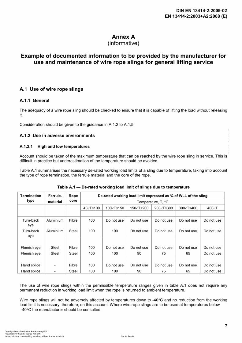
Table A.1 summarises the necessary de-rated working load limits of a sling due to temperature, taking into account the type of rope termination, the ferrule material and the core of the rope.
Table A.1 — De-rated working load limit of slings due to temperature
De-rated working load limit expressed as % of WLL of the sling Termination type
Ferrule. material
Rope core Temperature, T, °C
40<T≤100 100<T≤150 150<T≤200 200<T≤300 300<T≤400 400<T
Turn-back eye
Aluminium Fibre 100 Do not use Do not use Do not use Do not use Do not use
Turn-back eye
Aluminium Steel 100 100 Do not use Do not use Do not use Do not use
Flemish eye Steel Fibre 100 Do not use Do not use Do not use Do not use Do not use Flemish eye Steel Steel 100 100 90 75 65 Do not use
Hand splice - Fibre 100 Do not use Do not use Do not use Do not use Do not use Hand splice - Steel 100 100 90 75 65 Do not use
The use of wire rope slings within the permissible temperature ranges given in table A.1 does not require any permanent reduction in working load limit when the rope is returned to ambient temperature.
Wire rope slings will not be adversely affected by temperatures down to -40°C and no reduction from the working load limit is necessary, therefore, on this account. Where wire rope slings are to be used at temperatures below -40°C the manufacturer should be consulted.
DIN EN 13414-2:2009-02
Copyright Deutsches Institut Fur Normung E.V. Provided by IHS under license with DIN
Not for ResaleNo reproduction or networking permitted without license from IHS
--`,,```,,,,````-`-`,,`,,`,`,,`---
EN 13414-2:2003+A2:2008 (E)
8
A.1.2.2 Acidic conditions
Wire rope slings should not be used either immersed in acidic solutions or exposed to acid fumes.
Attention is drawn to the fact that certain production processes involve acidic solutions, fumes and sprays and in these circumstances the manufacturer’s advice should be sought.
A.1.2.3 Conditions in which the sling is likely to be subjected to attack (chemical, abrasive, etc.)
The manufacturer of the sling should be consulted, particularly if the sling is to be exposed to chemicals combined with high temperatures.
A.1.3 Use in hazardous conditions
The rating of slings for general lifting service excludes hazardous conditions including offshore activities, the lifting of persons and lifting of potentially dangerous loads such as molten metals, corrosive materials or fissile materials. In such cases the degree of hazard should be assessed by a competent person and the working load limit adjusted accordingly.
A.1.4 Actions to be taken before putting into first use
Before first use of the wire rope sling it should be ensured that:
a) the sling is precisely as ordered;
b) the manufacturer’s certificate is to hand;
c) the identification and working load limit marking on the sling correspond to the information on the certificate;
d) full details of the sling are recorded in a register of slings;
e) the actual use is to be as intended.
A.1.5 Information for safe use of the wire rope sling
A.1.5.1 Preparation
Before starting the lift, it should be ensured that the load is free to move and is not bolted down or otherwise obstructed.
Packing may be required where a rope comes into contact with a load in order to protect either the rope or the load or both, since sharp corners of hard material may bend or damage the rope or, conversely, the rope may damage the load because of high contact pressure. Corner protection should be used to prevent such damage.
In order to prevent dangerous swaying of the load and to position it for loading, a tag line is recommended.
When loads are accelerated or decelerated suddenly, dynamic forces occur which increase the stresses in the rope. Such situations, which should be avoided, arise from snatch or shock loading e.g. from not taking up the slack rope before starting to lift.
A.1.5.2 Mass of the load
It is essential that the mass of the load to be lifted is known
DIN EN 13414-2:2009-02
Copyright Deutsches Institut Fur Normung E.V. Provided by IHS under license with DIN
Not for ResaleNo reproduction or networking permitted without license from IHS
--`,,```,,,,````-`-`,,`,,`,`,,`---
EN 13414-2:2003+A2:2008 (E)
9
A.1.5.3 Stability of the load when first raised
It is assumed that the attachment point of the hook is directly above the centre of gravity of the load. To lift the load the following conditions should be met:
For loads with attachment points
a) For single-leg and single endless wire rope slings the attachment point should be vertically above the centre of gravity.
b) For two-leg wire rope slings the attachment points should be either side of and above the centre of gravity.
c) For three- and four-leg wire rope slings the attachment points should be distributed in plan around the centre of gravity. It is preferable that the distribution should be equal (but see A.1.5.6) and that the attachment points are above the centre of gravity.
If the attachment points using a) or b) are at or below the centre of gravity, other lifting arrangements should be used.
A.1.5.4 Angles for multi-leg slings
When using two-, three- and four-leg wire rope slings the attachment points and sling configuration should be selected to achieve angles between the sling legs and the vertical within the range marked on the sling. Preferably all angles to the vertical (angle β in figure A.1) should be equal (but see A.1.5.6). Angles to the vertical of less than 15° should be avoided if possible as they present a significantly greater risk of load imbalance.
All multi-leg slings exert a horizontal component of force (see figure A.1) which increases as the angle between the sling legs is increased. Care should always be taken to ensure that the load to be moved is able to resist the horizontal component of force without being damaged.
DIN EN 13414-2:2009-02
Copyright Deutsches Institut Fur Normung E.V. Provided by IHS under license with DIN
Not for ResaleNo reproduction or networking permitted without license from IHS
--`,,```,,,,````-`-`,,`,,`,`,,`---

EN 13414-2:2003+A2:2008 (E)
10
1. Loading of leg 2. Horizontal component of force Hatched area: not covered by tag The hatched area indicates angles greater than 60° to the vertical for which wire rope slings are not intended to be used.
Figure A.1 — Variation of wire rope sling leg loading with leg angle for a load of Q
A.1.5.5 Method of connection
A wire rope sling is usually attached to the load and the lifting machine by means of terminal fittings. Sling legs should not be twisted or knotted. The lifting point should be seated well down in a hook, never on the point or wedged in the opening; the sling hook should be free to incline in any direction so as to avoid bending. For the same reason, the terminal fitting should be free to incline in any direction on the hook to which it is fitted.
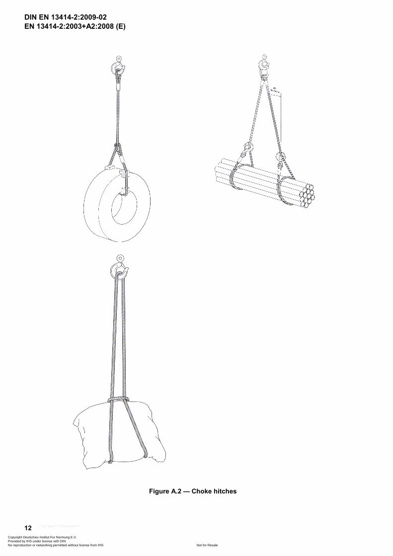
The rope may be passed under or through the load to form a choke hitch (see figure A.2) or basket hitch (see figure A.3). When using basket hitch method and where it is necessary, due to the danger of the load tilting, to use more than one sling, this should preferably be done in conjunction with a lifting beam having two upper connections to the crane hook.
When a wire rope sling is used in a choke hitch, the rope should be allowed to assume its natural angle and should not be hammered down.
When attaching the sling to the lifting hook, ensure that there is adequate clearance to permit articulation and to prevent damage to the sling. Never force, hammer or wedge a sling into position. If there is insufficient clearance, fit a shackle between the sling and the hook. To prevent the formation of kinks and subsequent weakening of the rope of slings having soft eye terminations, ensure that the effective diameter of the shackle pin / hook is at least twice the diameter of the rope.
In the case of a mutli-leg sling the tip of a sling hook should be directed outwards. No rope should be wrapped around a crane hook.
DIN EN 13414-2:2009-02
Copyright Deutsches Institut Fur Normung E.V. Provided by IHS under license with DIN
Not for ResaleNo reproduction or networking permitted without license from IHS
--`,,```,,,,````-`-`,,`,,`,`,,`---
EN 13414-2:2003+A2:2008 (E)
11
Sling legs may be attached to the load in several ways:
a) Straight leg
In this case lower terminals are connected directly to the attachment points. Selection of hooks and attachment points should be such that the load is carried in the seat of the hook and tip loading of the hook is avoided.
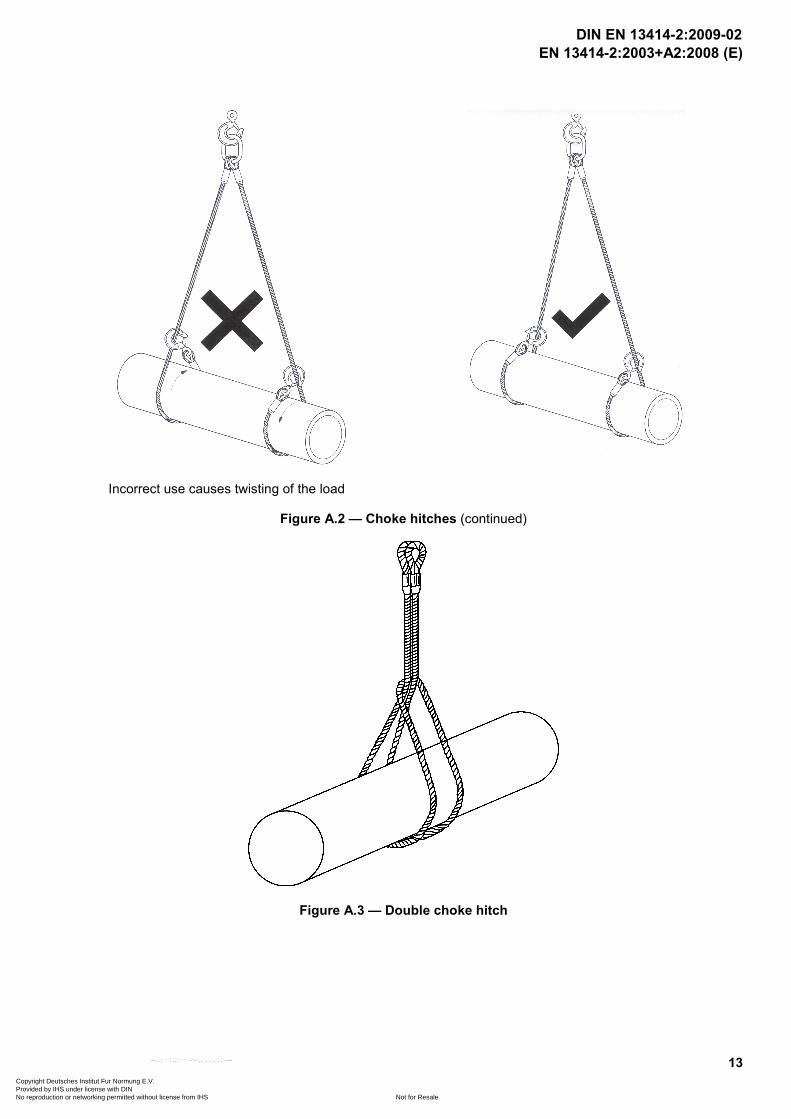
b) Choke hitch
In this case sling legs are passed through or under the load and the lower terminal back hooked or reeved onto the rope (see figure A.2). A single-leg sling may also be used in a double choke hitch(see Figure A.3).
This method can, therefore, be used where no suitable attachment points are available and has the additional advantage that the wire rope sling legs tend to bind the load together.
Where choke hitch is employed the working load limit (WLL) of the sling should be no more than 80 % of that marked.
If two or more wire rope sling legs are used in a choke hitch or a double choke hitch care should be taken:
1) if it is important, to avoid imparting a torque to the load, to align the chokes; or
2) if it is important, to avoid the load rolling or moving laterally when first lifted, to ensure that (at least) one leg passes either side of the load.
When endless slings are used they should be so placed such that any joining ferrules or splices are in the free length of the sling.
c) Basket hitch
There are two methods of forming a basket hitch; passing a single sling through a load or wrapping two slings around the load. The second method is not suitable where the slings are able to move towards each other when the load is lifted or when lifting loads which are not held together such as loose bundles; a choke hitch is preferred. Examples of basket hitches are given in figure A.4.
DIN EN 13414-2:2009-02
Copyright Deutsches Institut Fur Normung E.V. Provided by IHS under license with DIN
Not for ResaleNo reproduction or networking permitted without license from IHS
--`,,```,,,,````-`-`,,`,,`,`,,`---
EN 13414-2:2003+A2:2008 (E)
12
Figure A.2 — Choke hitches
DIN EN 13414-2:2009-02
Copyright Deutsches Institut Fur Normung E.V. Provided by IHS under license with DIN
Not for ResaleNo reproduction or networking permitted without license from IHS
--`,,```,,,,````-`-`,,`,,`,`,,`---
EN 13414-2:2003+A2:2008 (E)
13
Incorrect use causes twisting of the load
Figure A.2 — Choke hitches (continued)
Figure A.3 — Double choke hitch
DIN EN 13414-2:2009-02
Copyright Deutsches Institut Fur Normung E.V. Provided by IHS under license with DIN
Not for ResaleNo reproduction or networking permitted without license from IHS
--`,,```,,,,````-`-`,,`,,`,`,,`---

EN 13414-2:2003+A2:2008 (E)
14
Figure A.4 — Basket hitches
DIN EN 13414-2:2009-02
Copyright Deutsches Institut Fur Normung E.V. Provided by IHS under license with DIN
Not for ResaleNo reproduction or networking permitted without license from IHS
--`,,```,,,,````-`-`,,`,,`,`,,`---
EN 13414-2:2003+A2:2008 (E)
15
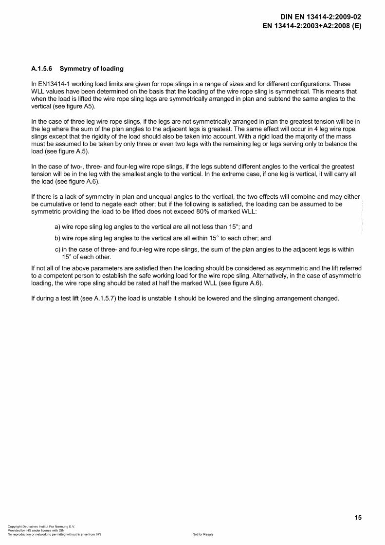
A.1.5.6 Symmetry of loading
In EN13414-1 working load limits are given for rope slings in a range of sizes and for different configurations. These WLL values have been determined on the basis that the loading of the wire rope sling is symmetrical. This means that when the load is lifted the wire rope sling legs are symmetrically arranged in plan and subtend the same angles to the vertical (see figure A5).
In the case of three leg wire rope slings, if the legs are not symmetrically arranged in plan the greatest tension will be in the leg where the sum of the plan angles to the adjacent legs is greatest. The same effect will occur in 4 leg wire rope slings except that the rigidity of the load should also be taken into account. With a rigid load the majority of the mass must be assumed to be taken by only three or even two legs with the remaining leg or legs serving only to balance the load (see figure A.5).
In the case of two-, three- and four-leg wire rope slings, if the legs subtend different angles to the vertical the greatest tension will be in the leg with the smallest angle to the vertical. In the extreme case, if one leg is vertical, it will carry all the load (see figure A.6).
If there is a lack of symmetry in plan and unequal angles to the vertical, the two effects will combine and may either be cumulative or tend to negate each other; but if the following is satisfied, the loading can be assumed to be symmetric providing the load to be lifted does not exceed 80% of marked WLL:
a) wire rope sling leg angles to the vertical are all not less than 15°; and
b) wire rope sling leg angles to the vertical are all within 15° to each other; and
c) in the case of three- and four-leg wire rope slings, the sum of the plan angles to the adjacent legs is within 15° of each other.
If not all of the above parameters are satisfied then the loading should be considered as asymmetric and the lift referred to a competent person to establish the safe working load for the wire rope sling. Alternatively, in the case of asymmetric loading, the wire rope sling should be rated at half the marked WLL (see figure A.6).
If during a test lift (see A.1.5.7) the load is unstable it should be lowered and the slinging arrangement changed.
DIN EN 13414-2:2009-02
Copyright Deutsches Institut Fur Normung E.V. Provided by IHS under license with DIN
Not for ResaleNo reproduction or networking permitted without license from IHS
--`,,```,,,,````-`-`,,`,,`,`,,`---

EN 13414-2:2003+A2:2008 (E)
16
Figure A.5 — Multi-leg slings: Load distribution
β 1β 2
2
3
1
1. Centre of gravity 2. High load in this leg 3. Load P
Figure A.6 — Asymmetric loading
DIN EN 13414-2:2009-02
Copyright Deutsches Institut Fur Normung E.V. Provided by IHS under license with DIN
Not for ResaleNo reproduction or networking permitted without license from IHS
--`,,```,,,,````-`-`,,`,,`,`,,`---

EN 13414-2:2003+A2:2008 (E)
17
A.1.5.7 Safety of lift
Hands and other parts of the body should be kept away from the sling to prevent injury as the slack is taken up. When ready to lift, the slack should be taken up until the rope is taut. The load should be raised slightly and a check made that it is secure and assumes the position intended. Persons undertaking the lift should be aware of the potential hazards associated with the load tilting or swaying. This is especially important with basket or other loose hitches where friction retains the load.
NOTE ISO 12480-1 gives advice for planning and management of the lifting operation and the adoption of safe systems of working.
A.1.5.8 Multi-leg wire rope slings with less than the full number of legs in use
As a general principle, wire rope slings should be used only for the purpose for which they have been designed. In practice, however, occasions may arise when a lift needs to be made using a smaller number of legs than the number of legs in the sling. In such cases the WLL should be reduced from that marked on the sling by applying the relevant factor given in table A.2.
Legs that are not in use should be hooked back to reduce the risk of such legs swinging freely, or snagging when the load is moved.
Table A.2— Working load limit (WLL) factors
Types of sling Number of legs used Factor to apply to marked WLL
two-leg 1 1/2 three- and four-leg 2 2/3 three- and four-leg 1 1/3
A.1.5.9 Working load limit (WLL)
Taking into consideration A.1.5.1 to A.1.5.8 and the cumulative effects of de-rating, the method of slinging should be decided and a suitable wire rope sling or wire rope slings selected so that the mass to be lifted does not exceed the WLL.
A.1.5.10 Landing the load
The landing site should be prepared. It should be ensured that the ground or floor is of adequate strength to take the load taking account of any voids, ducts, pipes etc. which may be damaged or collapse. It should also be ensured that there is adequate access to the site and that it is clear of any unnecessary obstacles and people. It is preferable to use timber bearers or similar material to avoid trapping the sling or to protect the floor or load or to ensure the stability of the load when landed.
The load should be landed carefully ensuring that hands and feet are kept clear. Care should be taken to avoid trapping the wire rope sling beneath the load as this may damage it. Before allowing the rope to become slack, the load should be checked to ensure that it is properly supported and stable. This is especially important when several loose objects are in basket hitch and choke hitch. When the load is safely landed the wire rope sling should be carefully removed to avoid damage or snagging or cause the load to topple over. The load should not be rolled off the sling as this may damage the sling.
DIN EN 13414-2:2009-02
Copyright Deutsches Institut Fur Normung E.V. Provided by IHS under license with DIN
Not for ResaleNo reproduction or networking permitted without license from IHS
--`,,```,,,,````-`-`,,`,,`,`,,`---
EN 13414-2:2003+A2:2008 (E)
18
A.1.5.11 Storage of wire rope slings
When not in use wire rope slings should normally be kept on a properly designed rack. They should not be left lying on the ground where they may be damaged.
If the wire rope slings are to be left suspended from a crane hook, the sling hooks should be engaged in an upper link to reduce the risk of sling legs swinging freely or snagging.
If it is likely that wire rope slings will be out of use for some time they should be cleaned, dried and protected from corrosion, e.g. lightly oiled.
A.2 Inspection, thorough examination and maintenance
A.2.1 General
During service, wire rope slings are subjected to conditions that affect their safety. It is necessary, therefore, to ensure, as far as is reasonably practicable, that the sling is safe for continued use.
The sling should be inspected for any obvious signs of deterioration before each use, see A.2.2.
If, at any time there is reason to doubt the safe condition of the sling, it should be withdrawn from service and subjected to a thorough examination, see A.2.3.
If the tag or label identifying the sling and its working load limit becomes detached and the necessary information is not marked on the master link, or by some other means, the sling should be withdrawn from service.
A.2.2 Inspection
An inspection is a visual check on the condition of the sling to identify any obvious damage or deterioration that might affect its fitness for use.
The sling should be withdrawn from service and referred to a competent person for thorough examination if any of the following is observed before each use:
a) Illegible sling markings, i.e. sling identification and/or working load limit. b) Wear, distortion and/or cracking of the upper or lower terminals and/or ferrules. c) Concentration(s) of broken wires. d) Severe rope distortion, such as kinks or protrusion of the core. e) Significant rope wear. f) Corrosion. g) Heat damage.
!Following examination of a sling with illegible markings and unless it can be shown that the sling was fabricated from rope having a grade other than 1770, the competent person should assume that the rope grade is 1770 when determining the new working load limit (WLL)."
A.2.3 Thorough examination and discard criteria
A.2.3.1 General
A thorough examination should be carried out at intervals not exceeding twelve months. This interval should be less where deemed necessary in the light of service conditions.
To facilitate examination, slings may need to be cleaned so as to be free from oil, dirt and rust prior to examination. This can usually be accomplished by using a wire brush. Other methods may be used providing that the parent metal is not damaged. Methods to avoid are those using acids, overheating or removal of metal.
Records of such examinations should be maintained.
DIN EN 13414-2:2009-02
Copyright Deutsches Institut Fur Normung E.V. Provided by IHS under license with DIN
Not for ResaleNo reproduction or networking permitted without license from IHS
--`,,```,,,,````-`-`,,`,,`,`,,`---

EN 13414-2:2003+A2:2008 (E)
19
The sling should be withdrawn from service if any of the conditions in A.2.3.2 to A.2.3.9 are present, reached or exceeded.
A.2.3.2 Sling markings
The sling markings, i.e. information on the sling identification and /or the working load limit, are illegible.
A.2.3.3 Damaged upper and lower terminals
Wear, distortion or cracking of the upper or lower terminals.
NOTE Particular attention should be paid to signs of opening up, distortion or cracking of the hook, distortion and wear of links or the closing of the thimble, indications that the sling may have been overloaded.
A.2.3.4 Damaged rope terminations
Wear, distortion or cracking of ferrules or the pulling out of a splice.
A.2.3.5 Broken wires
A.2.3.5.1 General
Broken wires are detrimental because of
a) the possibility of injury to the user’s hands; b) the loss of strength in the rope.
Broken wires are usually caused by mechanical damage, although corrosion may also be a factor.
The appearance of well distributed broken wires may have no marked effect on the strength of the sling but the discard criteria in A.2.3.5.2 and A.2.3.5.3 should be adopted for randomly distributed broken wires and concentrated broken wires respectively.
NOTE To prevent injury to the user’s hands, protruding broken wires can be broken off in the valleys between the strands by reverse bending the wire, with the help of pliers, until fracture occurs. Such actions should be recorded.
A.2.3.5.2 Randomly distributed broken wires
6 randomly distributed broken outer wires in a length of 6d but no more than 14 randomly distributed broken wires in a length of 30d where d is the nominal rope diameter.
A.2.3.5.3 Concentrated broken wires
3 adjacent broken outer wires in one strand.
A.2.3.6 Rope distortion
Kinking, crushing, birdcaging or core protrusion or other damage which distorts the rope structure.
NOTE The main thing to look for is wires or strands that are pushed out of their original positions in the rope. Slight bends in a rope where wires or strands are still relatively in their original positions would not be considered serious damage.
A.2.3.7 Rope wear
10% of the nominal rope diameter (d).
DIN EN 13414-2:2009-02
Copyright Deutsches Institut Fur Normung E.V. Provided by IHS under license with DIN
Not for ResaleNo reproduction or networking permitted without license from IHS
--`,,```,,,,````-`-`,,`,,`,`,,`---
EN 13414-2:2003+A2:2008 (E)
20
A.2.3.8 Corrosion
Pitting of the wires or loss of flexibility of the rope due to severe internal corrosion.
NOTE Corrosion may occur where slings have been improperly stored or have been used in particularly corrosive conditions, such as moving loads in and out of acid/alkali baths. The effect is readily identified through the loss of flexibility and roughness to the touch. While light surface rusting is unlikely to affect the rope strength, it may be indicative of internal corrosion, the effect of which is not predictable.
A.2.3.9 Heat damage
Heat damage as evidenced by discolouration of the wires, loss of lubrication or pitting of the wires caused by electric arcing.
A.2.4 Maintenance
Any replacement component or part of the wire rope sling should be in accordance with the appropriate European Standard for that component or part.
Components that are cracked, visibly distorted or twisted, severely corroded or have deposits that cannot be removed should be discarded and replaced.
Minor damage such as nicks and gouges to terminal fittings may be removed by careful grinding or filing. The surface should blend smoothly into adjacent material without abrupt change of section. The complete removal of the damage should not reduce the thickness of the section at that point to less than the manufacturer’s specified minimum dimensions or by more than 10% of nominal thickness of the section.
DIN EN 13414-2:2009-02
Copyright Deutsches Institut Fur Normung E.V. Provided by IHS under license with DIN
Not for ResaleNo reproduction or networking permitted without license from IHS
--`,,```,,,,````-`-`,,`,,`,`,,`---

EN 13414-2:2003+A2:2008 (E)
21
Annex ZA
(informative)
####Relationship between this European Standard and the Essential Requirements of EU Directive 98/37/EC
This European Standard has been prepared under a mandate given to CEN by the European Commission and the European Free Trade Association to provide a means of conforming to Essential Requirements of the New Approach Directive 98/37/EC amended by 98/79/CE on machinery.
Once this standard is cited in the Official Journal of the European Communities under that Directive and has been implemented as a national standard in at least one Member State, compliance with the normative clauses of this standard confers, within the limits of the scope of this standard, a presumption of conformity with the relevant Essential Requirements of that Directive and associated EFTA regulations.
WARNING - Other requirements and other EU Directives may be applicable to the product(s) falling within the scope of this standard.$
DIN EN 13414-2:2009-02
Copyright Deutsches Institut Fur Normung E.V. Provided by IHS under license with DIN
Not for ResaleNo reproduction or networking permitted without license from IHS
--`,,```,,,,````-`-`,,`,,`,`,,`---
EN 13414-2:2003+A2:2008 (E)
22
Annex ZB (informative)
####Relationship between this European Standard and the Essential
Requirements of EU Directive 2006/42/EC
This European Standard has been prepared under a mandate given to CEN by the European Commission and the European Free Trade Association to provide a means of conforming to Essential Requirements of the New Approach Directive 2006/42/EC on machinery.
Once this standard is cited in the Official Journal of the European Communities under that Directive and has been implemented as a national standard in at least one Member State, compliance with the normative clauses of this standard confers, within the limits of the scope of this standard, a presumption of conformity with the relevant Essential Requirements of that Directive and associated EFTA regulations.
WARNING - Other requirements and other EU Directives may be applicable to the product(s) falling within the scope of this standard.$
DIN EN 13414-2:2009-02
Copyright Deutsches Institut Fur Normung E.V. Provided by IHS under license with DIN
Not for ResaleNo reproduction or networking permitted without license from IHS
--`,,```,,,,````-`-`,,`,,`,`,,`---
EN 13414-2:2003+A2:2008 (E)
23
Bibliography
[1] EN 1677-1, Components for slings – Safety - Part 1: Forged steel components - Grade 8
[2] EN 1677-2, Components for slings – Safety - Part 2: Forged steel lifting hooks with latch - Grade 8
[3] EN 1677-3, Components for slings – Safety - Part 3: Forged steel self-locking hooks - Grade 8
[4] EN 1677-4, Components for slings – Safety - Part 4: Links - Grade 8
[5] EN 1677-5, Components for slings – Safety - Part 5: Forged steel lifting hooks with latch - Grade 4
[6] EN 1677-6, Components for slings – Safety - Part 6: Links - Grade 4
[7] EN 10002-2: 1991, Metallic materials - Tensile testing - Part 2: Verification of the forces measuring system of the tensile testing machines.
[8] ISO 12480-1, Cranes - Safe use - Part 1 - General
DIN EN 13414-2:2009-02
Copyright Deutsches Institut Fur Normung E.V. Provided by IHS under license with DIN
Not for ResaleNo reproduction or networking permitted without license from IHS
--`,,```,,,,````-`-`,,`,,`,`,,`---