steel/ptfe-pipes and fittings - fluoroplastic...
TRANSCRIPT

Steel/PTFE-Pipes and Fittings ANSI 16.5 Class 150 Blind Flanges
Spacers and Armoured Spacers
Elbows 45° and 90°
Crosses and Reducing Crosses
Reducers concentric and eccentric
Pipes (straight)
Tees and Reducing Tees Lateral Tees (45°-Branch) Instrument-Tappings Reducing Flanges

f.e.s.
fluoroplastic engineering service
f.e.s. GmbH & Co. KG • Senefelderstrasse 1/T5 • D - 63110 Rodgau • Telephone (06106) 88 61 97 • E-Mail: [email protected]
PTFE-lined Pipes, -Fittings and supplementary PTFE-lined Items General Information
Standard Performance Identification Wall Thicknesses Boundary Measures and Tolerances
Supervision and Quality Assurance Raw Materials Semi-finished Products Items Ready for Use Inspection Certificates/Reports Test Reports/Certificates
Straight pipes are equipped with loose and fixed flanges, fittings typically with fixed flanges. Extra loose flanges, however, are available upon request.. With the exception of spacers (Type F) every type of lined item displays the manufacturer’s logo (LMP). Supplementary data are being stamped in terms of nominal size, pressure rating, and material of lining and production date (month/year) respectively. A given serial number will allow an unequivocal iden-tification in context with the quality assurance. Items lined with electrostatically conductive lining display the ""-Symbol. Wall thicknesses for pipes follow DIN 2848 Part 4 Column 2, for elbows DIN 2605 Part 1, Tees, Crosses und Reducing pieces ASME/ANSI Schedule 40 (DN 15 - DN 150), and commencing DN 200 ASME/ANSI Schedule 20. The thickness of the liner goes up with increasing dimensions. The Standard thicknesses for PTFE range from 3 to 7 mm (DN 15 to DN 300). Electrostatical-ly conductive lining will be 6 - 8 % inferior on account of higher shrinkage. The accepted variances remain in full accordance with the generally accepted GKV-Rules and yield 10 % in terms of wall thickness and 3 % in diameter. Boundary measures and tolerances thereof are in compliance with DIN 2848 Part 3. Incoming raw materials, semi-finished products and readily manufactured items undergo regular quality assurance inspections. PTFE-Granulates are routinely scrutinized with respect to density, elongation at break, tensile strength, humidity, particle size and sintering behaviour. The lining is repeatedly controlled in terms of porosity, crevices and weak points by dint of spark tests following the regulation DIN 28055 Part 2. The applied voltage varies between 15-35 kV in dependence of the individual wall thickness. In supplement hereto externally manufactured semi finished items are visually inspected and dimensionally controlled. Prior to release the concise items undergo pressure tests with 1.5-fold nominal pressure at ambient temperature. The manufacturing process, both the steel handling and the PTFE-lining part are regularly supervised by authorised organisations (Notified Bodies) Welding technologies are supervised in consideration of pertinent welding Standards, such as AD-Merkblatt HP 2/1 and DIN EN 288-3; Welding approvals acc. to DIN EN 287-1 and AD-Merkblatt HP 3 are simultaneously taken into account. Pre-requisites to grant the manufacturing of pipes, fittings and supplementary lined items meet the requirements of the Pressure Equipment Directives (2014/68/EU) in conjunction with the Technical Guidelines TRR 100 and AD-Merkblatt HP 0 / DIN EN 729-3. 2014/68/EU-Approvals were certified repeatedly for Module A (Category I), Module A1 (Category II) and B + C1 (Category III). Declarations of Conformity are regularly distributed together with the manufac-tured items. The tightness of lined flange connections meets the requirements of the Ger-man Regulation of Clean Air (TA-Luft) Paragraph 5.2.6.4 (2002) and the VDI-Regulation (VDI 2440, Paragraph 3.3.1.4 (Nov. 2000) respectively. Test Reports acc. to EN 10204 2.2 or else Inspection Certificates acc. to EN 10204 3.1 are available upon request at extra charge. The necessity of certifi-cates must be declared at the point of order placement.
Subject to change until further notice SPPÜ2DD © f.e.s. Version 01/2016

f.e.s.
fluoroplastic engineering servicef.e.s. GmbH & Co. KG • Senefelderstraße 1/T5 • D - 63110 Rodgau • Telefon (06106) 88 61 97 • E-Mail: [email protected]
PTFE-Lined Pipes and -Fittings Operational Limits
Chemical Resistance As fully fluorinated polymer PTFE features excellent chemical properties. A very few limitations, however, have to be taken into account:
Alkali metals, such as sodium and potassium, besides alkaline-earth metals
(i.e. calcium), either molten or as complex compound lead to destruction of PTFE and to degradation of the polymer structure.
Fluorinated carbohydrates (Freon®) create swellings, occasionally even at ambient temperature. Limited exposure may turn out reversible, extended contact, however, lead to permanent volume increase with substantially re-stricted physical properties.
Elementary fluorine, halogens und chlorine trifluoride reveal no detrimental effect at ambient temperature. At elevated temperature levels intensified re-actions up to complete degradation will be very likely.
Benzyl chloride, dimethylformamide and fuming nitric acid besides nitridic acid create at elevated temperatures a structural degradation..
Monomers of Styrene, Butadiene, Acrylonitrile and further homologues tend to penetrate into the molecular structure giving rise to spontaneous polymer-ization leading to gain in volume and structural failure (Popcorn-Effect).
Radiation with boosting energy of >10kGy may diminish the mechanical properties by 50% or more.
Vacuum Resistance PTFE-lined pipes and fittings reveal limited vacuum resistance. Individual border-
lines for Linings in “Standard Duty” and “Heavy Duty” are displayed underneath.
Vacuum Resistance for „Standard Duty“ PTFE-Lining; Values expressed in mbar and in kPa.
Dimension ½“ ¾“ 1“ 1¼“ 1½“ 2“ 2½“ 3“ 4“ 5“ 6“ 8“ 10“ 12“PTFE-Wall Thickness (mm) 3,0 3,0 3,0 3,0 3,0 3,0 3,5 4,0 4,5 4,5 5,0 6,0 7,0 7,0 Pressure Rating (lbs/inch²) 150 150 150 150 150 150 150 150 150 150 150 150 150 150 Minimum Temperature (°C) -10 -10 -10 -10 -10 -10 -10 -10 -10 -10 -10 -10 -10 -10Maximum Temperature (°C) 200 200 200 200 200 200 200 200 200 200 200 200 200 200 Vacuum Resistance (mbar) 10 10 10 10 10 10 10 10 200 300 500 600 800 800 Vacuum Resistance (kPa) 1 1 1 1 1 1 1 1 20 30 50 60 80 80
Vacuum Resistance for “Heavy Duty” PTFE-Lining (strengthened PTFE-Wall thickness); Values expressed in mbar and kPa.
Dimension ½“ ¾“ 1“ 1¼“ 1½“ 2“ 2½“ 3“ 4“ 5“ 6“ 8“ 10“ 12“PTFE-Wall Thickness (mm) 3,0 3,0 3,0 3,0 3,0 3,0 3,5 4,0 7,0 7,0 8,0 9,5 11,0 11,0Pressure Rating (lbs/inch²) 150 150 150 150 150 150 150 150 150 150 150 150 150 150Minimum Temperature (°C) -10 -10 -10 -10 -10 -10 -10 -10 -10 -10 -10 -10 -10 -10Maximum Temperature (°C) 200 200 200 200 200 200 200 200 200 200 200 200 200 200 Vacuum Resistance (mbar) 10 10 10 10 10 10 10 10 10 20 30 50 80 100 Vacuum Resistance (kPa) 1 1 1 1 1 1 1 1 1 2 3 5 8 10
Vacuum Resistance based upon defined operation temperatures; Values expressed in mbar.
„Standard DutySPTFE „Standard Duty“ PTFE „Heavy Duty“ Dimension ½“ ¾“ 1“ 1¼“ 1½“ 2“ 2½“ 3“ 4“ 5“ 6“ 8“ 10“ 12“Operation Temperature 20 °C 1 1 1 1 1 1 1 1 20 30 50 60 80 80 Operation Temperature 20 °C 1 1 1 1 1 1 1 1 1 2 3 5 8 10Operation Temperature 50 °C 3 3 3 3 3 3 3 3 50 75 130 150 200 200Operation Temperature 50 °C 3 3 3 3 3 3 3 3 3 5 10 15 20 30 Operation Temperature 100 °C 5 5 5 5 5 5 5 5 100 150 250 300 400 400 Operation Temperature 100 °C 5 5 5 5 5 5 5 5 5 10 15 30 40 50 Operation Temperature 150 °C 8 8 8 8 8 8 8 8 150 225 380 450 600 600 Operation Temperature 150 °C 8 8 8 8 8 8 8 8 8 15 25 40 60 80 Operation Temperature 200 °C 10 10 10 10 10 10 10 10 200 300 500 600 800 800 Operation Temperature 200 °C 10 10 10 10 10 10 10 10 10 20 30 50 80 100
Electrostatically conductive lining results in reduced vacuum resistance of approximately 15 %.
Subject to change without further notice SPPÜ3DD © f.e.s. Version 01/2016

f.e.s. fluoroplastic engineering servicef.e.s. GmbH & Co. KG • Senefelderstrasse 1/T5 D - 63110 Rodgau • Telephone (06106) 88 61 97 • E-Mail: [email protected]
REQUIRED SIZES AND LENGTHS OF STUD BOLTS AND NUTS FOR ANSI 150 lbs. FLANGES
s
s
h1h1
mm
l1
D
d2
Dfixed flange
fixed flange
s
s
loose flange
fixed flange
d2 h1m
mh2
l2
h2m
D
d2
loose flange
s
s
loose flange
h2m
l3
ANSI 150 lbs. flanges – regular PTFE-Thickness (“Standard Duty”)
DN s n x d2 h1 h2 D m (ca)1
l1 l2 l3
½“ 3 4 x 15,9 13,6 23,1 ½” 14 55 65 75
¾“ 3 4 x 15,9 15,2 26,3 ½” 14 55 70 80
1“ 3 4 x 15,9 17,3 28,4 ½” 14 60 75 85
1¼“ 3 4 x 15,9 18,9 30,0 ½” 14 65 75 85
1½“ 3 4 x 15,9 20,5 31,6 ½” 14 70 80 90
2“ 3 4 x 19,0 22,1 36,2 5/ 8” 17,5 80 90 110
2½“ 3,5 4 x 19,0 25,2 39,4 5/ 8” 17,5 90 100 110
3“ 4 4 x 19,0 26,8 42,6 5/ 8” 17,5 90 100 120
4“ 4,5 8 x 19,0 26,8 42,6 5/ 8” 17,5 90 100 120
5“ 4,5 8 x 22,2 26,8 44,2 ¾” 21 100 110 130
6“ 5 8 x 22,2 30,4 46,3 ¾” 21 100 120 130
8“ 6 8 x 22,2 33,1 53,7 ¾” 21 110 130 150
10“ 7 12 x 25,4 35,2 57,4 7/ 8” 24 120 140 160
12“ 7 12 x 25,4 36,8 58,9 7/ 8” 24 120 140 160
ANSI 150 lbs. flanges – strengthened PTFE-Thickness (“Heavy Duty”)
DN s n x d2 h1 h2 D m (ca)1
l1 l2 l3
½“ 3 4 x 15,9 13,6 23,1 ½” 14 55 65 75
¾“ 3 4 x 15,9 15,2 26,3 ½” 14 55 70 80
1“ 3 4 x 15,9 17,3 28,4 ½” 14 60 75 85
1¼“ 3 4 x 15,9 18,9 30,0 ½” 14 65 75 85
1½“ 3 4 x 15,9 20,5 31,6 ½” 14 70 80 90
2“ 3 4 x 19,0 22,1 36,2 5/ 8” 17,5 80 90 110
2½“ 3,5 4 x 19,0 25,2 39,4 5/ 8” 17,5 90 100 110
3“ 4 4 x 19,0 26,8 42,6 5/ 8” 17,5 90 100 120
4“ 7 8 x 19,0 29,3 45,1 5/ 8” 17,5 90 110 130
5“ 7 8 x 22,2 29,3 46,7 ¾” 21 100 120 140
6“ 8 8 x 22,2 33,4 49,3 ¾” 21 110 120 140
8“ 9,5 8 x 22,2 36,6 57,2 ¾” 21 120 140 160
10“ 11 12 x 25,4 39,2 61,4 7/ 8” 24 130 150 170
12“ 11 12 x 25,4 40,8 62,9 7/ 8” 24 130 150 170
*) Including washer and heavy hexagonal nuts
Subject to change without notice Pipe ANSI 150 © f.e.s. Version 01/2016
f.e.s.
fluoroplastic engineering servicef.e.s. GmbH & Co. KG • Senefelderstrasse 1/T5 • D - 63110 Rodgau • Telephone 0049 6106 88 61 97 • E-;Mail: [email protected]
Carbon Steel/PTFE-lined Pipes and Fittings Assembly Instructions
for ANSI 150 lbs Flanges
Assembly Instructions for PTFE-lined Pipes and Fittings
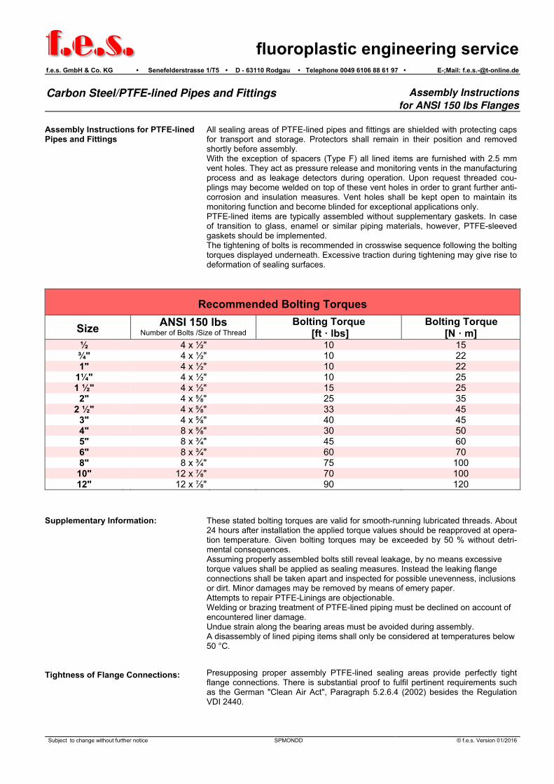
All sealing areas of PTFE-lined pipes and fittings are shielded with protecting caps for transport and storage. Protectors shall remain in their position and removed shortly before assembly. With the exception of spacers (Type F) all lined items are furnished with 2.5 mm vent holes. They act as pressure release and monitoring vents in the manufacturing process and as leakage detectors during operation. Upon request threaded cou-plings may become welded on top of these vent holes in order to grant further anti-corrosion and insulation measures. Vent holes shall be kept open to maintain its monitoring function and become blinded for exceptional applications only. PTFE-lined items are typically assembled without supplementary gaskets. In case of transition to glass, enamel or similar piping materials, however, PTFE-sleeved gaskets should be implemented. The tightening of bolts is recommended in crosswise sequence following the bolting torques displayed underneath. Excessive traction during tightening may give rise to deformation of sealing surfaces.
Recommended Bolting Torques
Size ANSI 150 lbs Number of Bolts /Size of Thread
Bolting Torque [ft · lbs]
Bolting Torque [N · m]
½ 4 x ½" 10 15 ¾" 4 x ½" 10 22 1" 4 x ½" 10 22
1¼" 4 x ½" 10 25 1 ½" 4 x ½" 15 25
2" 4 x " 25 35 2 ½" 4 x " 33 45
3" 4 x " 40 45 4" 8 x " 30 50 5" 8 x ¾" 45 60 6" 8 x ¾" 60 70 8" 8 x ¾" 75 100 10" 12 x " 70 100 12" 12 x " 90 120
Supplementary Information: Tightness of Flange Connections:
These stated bolting torques are valid for smooth-running lubricated threads. About 24 hours after installation the applied torque values should be reapproved at opera-tion temperature. Given bolting torques may be exceeded by 50 % without detri-mental consequences. Assuming properly assembled bolts still reveal leakage, by no means excessive torque values shall be applied as sealing measures. Instead the leaking flange connections shall be taken apart and inspected for possible unevenness, inclusions or dirt. Minor damages may be removed by means of emery paper. Attempts to repair PTFE-Linings are objectionable. Welding or brazing treatment of PTFE-lined piping must be declined on account of encountered liner damage. Undue strain along the bearing areas must be avoided during assembly. A disassembly of lined piping items shall only be considered at temperatures below 50 °C. Presupposing proper assembly PTFE-lined sealing areas provide perfectly tight flange connections. There is substantial proof to fulfil pertinent requirements such as the German "Clean Air Act", Paragraph 5.2.6.4 (2002) besides the Regulation VDI 2440.
Subject to change without further notice SPMONDD © f.e.s. Version 01/2016

f.e.s.
fluoroplastic engineering servicef.e.s. GmbH & Co. KG • Senefelderstrasse 1/T5 • D - 63110 Rodgau • Telefon (06106) 88 61 97 • E-Mail: [email protected]
PTFE-Lined Pipes and -Fittings Assembly Instructions
Advises for Assembly
Flat sealing areas of PTFE-lined pipes and fittings are secured with wooden protec-tors during transport and storage. Protectors shall be removed merely prior to as-sembly. Bolting material consisting of threaded bolts, hexagonal nuts and washers, based upon carbon steel 5.6 or else 8.8 represent the materials of choice. Threads shall be lubricated prior to assembly in order to ease its function. An assembly of PTFE-lined items is recommended omitting supplementary gas-kets. Transitions to glass piping, enamel lined piping and similar material, however, require supplementary gasket, preferably based upon PTFE-lined make-up. Tight-ening actions shall be executed in crosswise sequence in order to maintain sym-metrical assembly. Overexerted bolting torques may give rise to deformation of sealing areas.
Recommended Bolting Torques
DN PN 10/16 Number of Bolts /DIN Thread
PN 25/40 Number of Bolts /DIN Thread Bolting Torque [Nm]
15 4 x M12 4 x M12 15 20 4 x M12 4 x M12 22
25 4 x M12 4 x M12 22 32 4 x M16 4 x M16 25 40 4 x M16 4 x M16 25
50 4 x M16 4 x M16 35 65 4 x M16 4 x M16 45 80 8 x M16 8 x M16 45 100 8 x M16 8 x M20 50 125 8 x M16 8 x M24 60 150 8 x M20 8 x M24 70 200 8 x M20 12 x M24 100 250 12 x M20 12 x M27 100 300 12 x M20 16 x M27 120
Supplementary Remarks Sealing Tightness of Flange Connec-tions
All data mentioned above are valid for lubricated threads. About 24 hours after assembly all threaded connections shall be monitored with respect to applied bolting torques. The recommended torque values may be sur-passed by a maximum of 50 %. In case of leakage despite correctly applied bolting torques it is advisable not to exceed the given torque values the involved sealing areas shall be inspected for unevenness and surface inclusions besides possible coarseness. Interfering distor-tions must be smoothened and straightened out. Lesser surface lesions may be reduced by grinding actions. Repair actions of PTFE-lined areas are beyond acceptance. Welding and soldering actions in close vicinity to PTFE-Lined areas must be ex-cluded, due to possible damage of lining material. Inacceptable constraints are expected to create untimely malfunction of the lined item. A disassembly of PTFE-lined items shall be executed only at temperatures below 50 °C. PTFE-lined flange connections represent perfect sealing systems when properly assembled. They meet the pre-requisites of the Federal German Clean Air Act (TA-Luft, chapter 5.2.6.4.(2002) in conjunction with the VDI-Regulation 2440.
Änderungen vorbehalten SPMONDD © f.e.s. Version 01/2016

f.e.s. fluoroplastic engineering servicef.e.s. GmbH & Co. KG • Senefelderstrasse 1/T5 D - 63110 Rodgau • Telephone (06106) 88 61 97 • E-Mail: [email protected]
FLANGED PIPE according to ANSI B 16.5 Class 150
Mat erial specif icat ion: Tubes: ASTM A 106 Grade B according t o ANSI B 36.10
API 5L Grade B according t o ANSI B 36.10
Flanges: ASTM A 105 according t o ANSI B 16.5
Lining: Virgin PTFE according t o ASTM-D 4894 - 4895
Del ivery t erms: according t o DIN 2874
Dimensions expressed in mm
L DN 15 ÷ 300: 3.000max.
d d 1d 4k
h h
d 2
1 2
D
s f
s
DN d1 sf d s n x d2 d4 k D h1 h2
½“ 24.0 3.00 12 3 4 x 15.9 35 60.3 88.9 13.6 23.1
¾“ 24.0 3.00 12 3 4 x 15.9 43 69.8 98.4 15.2 26.3
1“ 33.4 3.38 19 3 4 x 15.9 51 79.4 107.9 17.3 28.4
1¼“ 42.2 3.56 28 3 4 x 15.9 64 88.9 117.5 18.9 30.0
1½“ 48.3 3.68 32 3 4 x 15.9 73 98.4 127.0 20.5 31.6
2“ 60.3 3.91 44 3 4 x 19.0 92 120.6 152.4 22.1 36.2
2½“ 73.0 5.16 61 3.5 4 x 19.0 105 139.7 177.8 25.2 39.4
3“ 88.9 5.49 69 4 4 x 19.0 127 152.4 190.5 26.8 42.6
4“ 114.3 6.02 94 4.5 8 x 19.0 157 190.5 228.6 26.8 42.6
5“ 141.3 6.55 121 4.5 8 x 22.2 185 215.9 254.0 26.8 44.2
6“ 168.3 7.11 144 5 8 x 22.2 216 241.3 279.4 30.4 46.3
8“ 219.1 6.35 194 6 8 x 22.2 270 298.4 342.9 33.1 53.7
10“ 273.0 6.35 246 7 12 x 25.4 324 361.9 406.4 35.2 57.4
12” 323.8 6.35 297 7 12 x 25.4 381 431.8 482.6 36.8 58.9
16” 406.4 7.9 374 8 16 x 28.6 470 539.7 596.9 44.6 68.6
20“ 508.0 11.0 468 9 20 x 31.7 585 635.0 698.5 52.0 78.0
St eel t ubes acc. t o Schedule 40 up t o 6” (included) and Schedule 20 f rom 8” t o 20” respect ively
Upon demand “ Heavy Dut y” l inings for vacuum services
Vent holes upon operat or’ s request
Subject to change without notice Pipe ANSI 150 © f.e.s. Version 01/2016

f.e.s.
fluoroplastic engineering servicef.e.s. GmbH & Co. KG • Senefelderstrasse 1/T5 D - 63110 Rodgau • Telephone (06106) 88 61 97 • E-Mail: [email protected]
FLANGED 45° BEND according to ANSI B 16.5 Class 150
Mat erial specif icat ion: St eel f rame: ASTM A 234 Grade WPB according t o ANSI B 16.28
Flanges: ASTM A 105 according t o ANSI B 16.5
Lining: Virgin PTFE according t o ASTM-D 4894
Del ivery t erms: according t o DIN 2874
Dimensions expressed in mm
D
k
d
l /l
34
l /l
34
r
4
s
DN s Elbow Type r l3 l4 d4 k D
½“ 3 L. R. 38.1 45 35 60.3 88.9
¾“ 3 L. R. 28.6 45 43 69.8 98.4
1“ 3 L. R. 38.1 45 51 79.4 107.9
1¼“ 3 L. R. 47.6 51 64 88.9 117.5
1½“ 3 L. R. 57.2 57 73 98.4 127.0
2“ 3 L. R. 50.8 64 92 120.6 152.4
2½“ 3.5 S. R. 63.5 76 105 139.7 177.8
3“ 4 S. R. 76.2 76 127 152.4 190.5
4“ 4.5 S. R. 101.6 102 157 190.5 228.6
5“ 4.5 S. R. 127.0 114 185 215.9 254.0
6“ 5 S. R. 152.4 127 216 241.3 279.4
8“ 6 S. R. 203.2 140 270 298.4 342.9
10“ 7 S. R. 254.0 165 324 361.9 406.4
12“ 7 S. R. 304.8 190 381 431.8 482.6
On demand “ Heavy Dut y” l ining available for vacuum services
St eel f rames according t o Schedule 40
Bends wit h individual angle degrees available upon request
Vent holes upon operat or’ s request
Subject to change without notice Ell 45 ANSI © f.e.s. Version 01/2016

f.e.s.
fluoroplastic engineering servicef.e.s. GmbH & Co. KG • Senefelderstrasse 1/T5 • D - 63110 Rodgau • Telephone (06106) 88 61 97 • E-Mail: [email protected]
FLANGED 90° BEND according to ANSI B 16.5 Class 150
Mat erial specif icat ion: St eel f rame: ASTM A 234 Grade WPB according t o ANSI B 16.28
Flanges: ASTM A 105 according t o ANSI B 16.5
Lining: Virgin PTFE according t o ASTM-D 4894
Del ivery t erms: according t o DIN 2874
Dimensions expressed in mm
l /l
1 2
l /l 2
1
rd k D
s4
DN s Elbow Type r l1 l2 d4 k D
½“ 3 L. R. 38.1 65 35 60.3 88.9
¾“ 3 L. R. 28.6 75 43 69.8 98.4
1“ 3 L. R. 38.1 89 51 79.4 107.9
1¼“ 3 L. R. 47.6 95 64 88.9 117.5
1½“ 3 L. R. 57.2 102 73 98.4 127.0
2“ 3 L. R. 50.8 114 92 120.6 152.4
2½“ 3.5 S. R. 63.5 127 105 139.7 177.8
3“ 4 S. R. 76.2 140 127 152.4 190.5
4“ 4.5 S. R. 101.6 165 157 190.5 228.6
5“ 4.5 S. R. 127.0 190 185 215.9 254.0
6“ 5 S. R. 152.4 203 216 241.3 279.4
8“ 6 S. R. 203.2 229 270 298.4 342.9
10“ 7 S. R. 254.0 279 324 361.9 406.4
12“ 7 S. R. 304.8 305 381 431.8 482.6
Upon demand “ Heavy Dut y” l inings for vacuum services
St eel f rames according t o Schedule 40
On request bends wit h individual angles
Vent holes upon operat or’ s request
Subject to change without notice Ell 90 ANSI 150 © f.e.s. Version 01/2016

f.e.s.
fluoroplastic engineering servicef.e.s. GmbH & Co. KG • Senefelderstrasse 1/T5 • D - 63110 Rodgau • Telephone (06106) 88 61 97 • E-Mail: [email protected]
EQUAL AND REDUCING TEES according to ANSI B 16.5 class 150
Mat erial specif icat ion: St eel f rame: ASTM A 234 Grade WPB according t o ANSI B 16.28
Flanges: ASTM A 105 according t o ANSI B 16.5
Lining: Virgin PTFE according t o ASTM-D 4894
Del ivery t erms: according t o DIN 2874 Dimensions expressed in mm
dkD
D
k
d
l
l l
DN
DN
1
2
42
2
2
1 1
4111
2
s 1
s2
DN1 s1 l1 d41 k1 D1 DN2 s2 l2 d42 k2 D2
½” 3 65 35 60.3 88.9 ½”
¾” 3 75 43 69.8 98.4 ¾”
¾” 3 75 43 69.8 98.4 ½” 3 75 35 60.3 88.9
1” 3 89 51 79.4 107.9 1”
1” 3 89 51 79.4 107.9 ¾” 3 89 43 69.8 98.4
1” 3 89 51 79.4 107.9 ½” 3 89 35 60.3 88.9
1¼” 3 95 64 88.9 117.5 1¼”
1¼” 3 95 64 88.9 117.5 1” 3 95 51 79.4 107.9
1¼” 3 95 64 88.9 117.5 ¾” 3 95 43 69.8 98.4
1¼” 3 95 64 88.9 117.5 ½” 3 95 35 60.3 88.9
1½” 3 102 73 98.4 127.0 1½”
1½” 3 102 73 98.4 127.0 1¼” 3 102 64 88.9 117.5
1½” 3 102 73 98.4 127.0 1” 3 102 51 79.4 107.9
1½” 3 102 73 98.4 127.0 ¾” 3 102 43 69.8 98.4
1½” 3 102 73 98.4 127.0 ½” 3 102 35 60.3 88.9
Subject to change without notice Tee1 ANSI 150 © f.e.s. Version 01/2015

f.e.s.
fluoroplastic engineering servicef.e.s. GmbH & Co. KG • Senefelderstrasse 1/T5 • D - 63110 Rodgau • Telephone (06106) 88 61 97 • E-Mail: [email protected]
EQUAL AND REDUCING TEES according to ANSI B 16.5 Class 150
Mat erial specif icat ion: St eel f rame: ASTM A 234 Grade WPB according t o ANSI B 16.28
Flanges: ASTM A 105 according t o ANSI B 16.5
Lining: Virgin PTFE according t o ASTM-D 4894
Del ivery t erms: according t o DIN 2874
Dimensions expressed in mm
DN1 s1 l1 d41 k1 D1 DN2 s2 l2 d42 k2 D2
2” 3 114 92 120.6 152.4 2”
2” 3 114 92 120.6 152.4 1½” 3 114 73 98.4 127.0
2” 3 114 92 120.6 152.4 1¼” 3 114 64 88.9 117.5
2” 3 114 92 120.6 152.4 1” 3 114 51 79.4 107.9
2” 3 114 92 120.6 152.4 ¾” 3 114 43 69.8 98.4
2” 3 114 92 120.6 152.4 ½” 3 114 35 60.3 88.9
2½” 3.5 127 105 139.7 177.8 2½”
2½” 3.5 127 105 139.7 177.8 2” 3 127 92 120.6 152.4
2½” 3.5 127 105 139.7 177.8 1½” 3 127 73 98.4 127.0
2½” 3.5 127 105 139.7 177.8 1¼” 3 127 64 88.9 117.5
2½” 3.5 127 105 139.7 177.8 1” 3 127 51 79.4 107.9
2½” 3.5 127 105 139.7 177.8 ¾” 3 127 43 69.8 98.4
2½” 3.5 127 105 139.7 177.8 ½” 3 127 35 60.3 88.9
3” 4 140 127 152.4 190.5 3”
3” 4 140 127 152.4 190.5 2½” 3.5 140 105 139.7 177.8
3” 4 140 127 152.4 190.5 2” 3 140 92 120.6 152.4
3” 4 140 127 152.4 190.5 1½” 3 140 73 98.4 127.0
3” 4 140 127 152.4 190.5 1¼” 3 140 64 88.9 117.5
3” 4 140 127 152.4 190.5 1” 3 140 51 79.4 107.9
3” 4 140 127 152.4 190.5 ¾” 3 140 43 69.8 98.4
3” 4 140 127 152.4 190.5 ½” 3 140 35 60.3 88.9
4” 4.5 165 157 190.5 228.6 4”
4” 4.5 165 157 190.5 228.6 3” 4 165 127 152.4 190.5
4” 4.5 165 157 190.5 228.6 2½” 3.5 165 105 139.7 177.8
4” 4.5 165 157 190.5 228.6 2” 3 165 92 120.6 152.4
4” 4.5 165 157 190.5 228.6 1½” 3 165 73 98.4 127.0
4” 4.5 165 157 190.5 228.6 1¼” 3 165 64 88.9 117.5
4” 4.5 165 157 190.5 228.6 1” 3 165 51 79.4 107.9
4” 4.5 165 157 190.5 228.6 ¾” 3 165 43 69.8 98.4
4” 4.5 165 157 190.5 228.6 ½” 3 165 35 60.3 88.9
5” 4.5 190 185 215.9 254.0 5”
5” 4.5 190 185 215.9 254.0 4” 4.5 190 157 190.5 228.6
5” 4.5 190 185 215.9 254.0 3” 4 190 127 152.4 190.5
5” 4.5 190 185 215.9 254.0 2½” 3.5 190 105 139.7 177.8
5” 4.5 190 185 215.9 254.0 2” 3 190 92 120.6 152.4
5” 4.5 190 185 215.9 254.0 1½” 3 190 73 98.4 127.0
5” 4.5 190 185 215.9 254.0 1¼” 3 190 64 88.9 117.5
5” 4.5 190 185 215.9 254.0 1” 3 190 51 79.4 107.9
Subject to change without notice Tee2 ANSI 150 © f.e.s. Version 01/2016

f.e.s.
fluoroplastic engineering servicef.e.s. GmbH & Co. KG • Senefelderstrasse 1/T5 • D - 63110 Rodgau • Telephone (06106) 88 61 97 • E-Mail: [email protected]
EQUAL AND REDUCING TEES according to ANSI B 16.5 class 150
Mat erial specif icat ion: St eel f rame: ASTM A 234 Grade WPB, according t o ANSI B 16.28
Flanges: ASTM A 105 according t o ANSI B 16.5
Lining: Virgin PTFE according t o ASTM-D 4894
Del ivery t erms: according t o DIN 2874
Dimensions expressed in mm
DN1 s1 l1 d41 k1 D1 DN2 s2 l2 d42 k2 D2
6” 5 203 216 241.3 279.4 6”
6” 5 203 216 241.3 279.4 5” 4.5 203 185 215.9 254.0
6” 5 203 216 241.3 279.4 4” 4.5 203 157 190.5 228.6
6” 5 203 216 241.3 279.4 3” 4 203 127 152.4 190.5
6” 5 203 216 241.3 279.4 2½” 3.5 203 105 139.7 177.8
6” 5 203 216 241.3 279.4 2” 3 203 92 120.6 152.4
6” 5 203 216 241.3 279.4 1½” 3 203 73 98.4 127.0
6” 5 203 216 241.3 279.4 1¼” 3 203 64 88.9 117.5
6” 5 203 216 241.3 279.4 1” 3 203 51 79.4 107.9
8” 6 229 270 298.4 342.9 8”
8” 6 229 270 298.4 342.9 6” 5 229 216 241.3 279.4
8” 6 229 270 298.4 342.9 5” 4.5 229 185 215.9 254.0
8” 6 229 270 298.4 342.9 4” 4.5 229 157 190.5 228.6
8” 6 229 270 298.4 342.9 3” 4 229 127 152.4 190.5
8” 6 229 270 298.4 342.9 2½” 3.5 229 105 139.7 177.8
8” 6 229 270 298.4 342.9 2” 3 229 92 120.6 152.4
10” 7 279 324 361.9 406.4 10”
10” 7 279 324 361.9 406.4 8” 6 279 270 298.4 342.9
10” 7 279 324 361.9 406.4 6” 5 279 216 241.3 279.4
10” 7 279 324 361.9 406.4 5” 4.5 279 185 215.9 254.0
10” 7 279 324 361.9 406.4 4” 4.5 279 157 190.5 228.6
10” 7 279 324 361.9 406.4 3” 4 279 127 152.4 190.5
10” 7 279 324 361.9 406.4 2½” 3.5 279 105 139.7 177.8
10” 7 279 324 361.9 406.4 2” 3 279 92 120.6 152.4
12” 7 305 381 431.8 482.6 12”
12” 7 305 381 431.8 482.6 10” 7 305 324 361.9 406.4
12” 7 305 381 431.8 482.6 8” 6 305 270 298.4 342.9
12” 7 305 381 431.8 482.6 6” 5 305 216 241.3 279.4
12” 7 305 381 431.8 482.6 5” 4.5 305 185 215.9 254.0
12” 7 305 381 431.8 482.6 4” 4.5 305 157 190.5 228.6
12” 7 305 381 431.8 482.6 3” 4 305 127 152.4 190.5
12” 7 305 381 431.8 482.6 2½” 3.5 305 105 139.7 177.8
12” 7 305 381 431.8 482.6 2” 3 305 92 120.6 152.4
Upon demand “ Heavy Dut y” l ining for vacuum services
St eel f rames according t o Schedule 40
Vent holes upon operat or’ s request
Subject to change without notice Tee3 ANSI 150 © f.e.s. Version 01/2016

f.e.s.
fluoroplastic engineering servicef.e.s. GmbH & Co. KG • Senefelderstrasse 1/T5 • D - 63110 Rodgau • Telephone (06106) 88 61 97 • E-Mail: [email protected]
45° LATERAL TEE according to ANSI B 16.5 Class 150
Mat erial specif icat ion: St eel f rame:A 106 Grade B, API 5L Grade B according t o
ANSI B 36.10
Flanges: ASTM A 105 according t o ANSI B 16.5
Lining: Virgin PTFE according t o ASTM-D 4894
Del ivery t erms: according t o DIN 2874
Dimensions expressed in mm
l l
l
k d D
2 1
1
4
45°s
DN s l1 l2 d4 k D
1“ 3 180 40 51 79.4 107.9
1¼“ 3 210 45 64 88.9 117.5
1½“ 3 220 50 73 98.4 127.0
2“ 3 240 55 92 120.6 152.4
2½“ 3.5 260 60 105 139.7 177.8
3“ 4 290 70 127 152.4 190.5
4“ 4.5 320 80 157 190.5 228.6
5“ 4.5 350 90 185 215.9 254.0
6“ 5 380 100 216 241.3 279.4
8“ 6 455 120 270 298.4 342.9
St eel f rames according t o Schedule 40
Upon demand “ Heavy Dut y” l ining for vacuum services
Reduced lat eral t ees and/ or lat eral t ees wit h dif ferent branch angles available on request
Vent holes upon operat or’ s request
Subject to change without notice Lateral Tee © f.e.s. Version 01/2016

f.e.s.
fluoroplastic engineering servicef.e.s. GmbH & Co. KG • Senefelderstrasse 1/T5 • D - 63110 Rodgau • Telephone (06106) 88 61 97 • E-Mail: [email protected]
EQUAL AND REDUCING CROSSES according to ANSI B 16.5 Class 150
Mat erial specif icat ion: St eel f rame: ASTM A 234 grade WPB according t o ANSI B 16.28
Flanges: ASTM A 105 according t o ANSI B 16.5
Lining: Virgin PTFE according t o ASTM-D 4894
Del ivery t erms: according t o DIN 2874
Dimensions expressed in mm
d 42
k
D
2
2
D k d 1 1 41
l l 1 1
l 2l 2
DN1
DN2
s 1
s2
DN1 s1 l1 d41 k1 D1 DN2 s2 l2 d42 k2 D2
½” 3 65 35 60.3 88.9 ½” 3 65 35 60.3 88.9
¾” 3 75 43 69.8 98.4 ¾” 3 75 43 69.8 98.4
¾” 3 75 43 69.8 98.4 ½” 3 75 35 60.3 88.9
1” 3 89 51 79.4 107.9 1” 3 89 51 79.4 107.9
1” 3 89 51 79.4 107.9 ¾” 3 89 43 69.8 98.4
1” 3 89 51 79.4 107.9 ½” 3 89 35 60.3 88.9
1¼” 3 95 64 88.9 117.5 1¼” 3 95 64 88.9 117.5
1¼” 3 95 64 88.9 117.5 1” 3 95 51 79.4 107.9
1¼” 3 95 64 88.9 117.5 ¾” 3 95 43 69.8 98.4
1¼” 3 95 64 88.9 117.5 ½” 3 95 35 60.3 88.9
1½” 3 102 73 98.4 127.0 1½” 3 102 73 98.4 127.0
1½” 3 102 73 98.4 127.0 1¼” 3 102 64 88.9 117.5
1½” 3 102 73 98.4 127.0 1” 3 102 51 79.4 107.9
1½” 3 102 73 98.4 127.0 ¾” 3 102 43 69.8 98.4
1½” 3 102 73 98.4 127.0 ½” 3 102 35 60.3 88.9
Subject to change without notice Cross1 ANSI © f.e.s. Version 01/2016

f.e.s.
fluoroplastic engineering servicef.e.s. GmbH & Co. KG • Senefelderstrasse 1/T5 • D - 63110 Rodgau • Telephone (06106) 88 61 97 • E-Mail: [email protected]
EQUAL AND REDUCING CROSSES according to ANSI B 16.5 Class 150
Mat erial specif icat ion: St eel f rame: ASTM A 234 Grade WPB according t o ANSI B 16.28
Flanges: ASTM A 105 according t o ANSI B 16.5
Lining: Virgin PTFE according t o ASTM-D 4894
Del ivery t erms: according t o DIN 2874
Dimensions expressed in mm
DN1 s1 l1 d41 k1 D1 DN2 s2 l2 d42 k2 D2
2” 3 114 92 120.6 152.4 2” 3 114 92 120.6 152.4
2” 3 114 92 120.6 152.4 1½” 3 114 73 98.4 127.0
2” 3 114 92 120.6 152.4 1¼” 3 114 64 88.9 117.5
2” 3 114 92 120.6 152.4 1” 3 114 51 79.4 107.9
2” 3 114 92 120.6 152.4 ¾” 3 114 43 69.8 98.4
2” 3 114 92 120.6 152.4 ½” 3 114 35 60.3 88.9
2½” 3.5 127 105 139.7 177.8 2½” 3,5 127 105 139.7 177.8
2½” 3.5 127 105 139.7 177.8 2” 3 127 92 120.6 152.4
2½” 3.5 127 105 139.7 177.8 1½” 3 127 73 98.4 127.0
2½” 3.5 127 105 139.7 177.8 1¼” 3 127 64 88.9 117.5
2½” 3.5 127 105 139.7 177.8 1” 3 127 51 79.4 107.9
2½” 3.5 127 105 139.7 177.8 ¾” 3 127 43 69.8 98.4
2½” 3.5 127 105 139.7 177.8 ½” 3 127 35 60.3 88.9
3” 4 140 127 152.4 190.5 3” 4 140 127 152.4 190.5
3” 4 140 127 152.4 190.5 2½” 3.5 140 105 139.7 177.8
3” 4 140 127 152.4 190.5 2” 3 140 92 120.6 152.4
3” 4 140 127 152.4 190.5 1½” 3 140 73 98.4 127.0
3” 4 140 127 152.4 190.5 1¼” 3 140 64 88.9 117.5
3” 4 140 127 152.4 190.5 1” 3 140 51 79.4 107.9
3” 4 140 127 152.4 190.5 ¾” 3 140 43 69.8 98.4
3” 4 140 127 152.4 190.5 ½” 3 140 35 60.3 88.9
4” 4.5 165 157 190.5 228.6 4” 4.5 165 157 190.5 228.6
4” 4.5 165 157 190.5 228.6 3” 4 165 127 152.4 190.5
4” 4.5 165 157 190.5 228.6 2½” 3.5 165 105 139.7 177.8
4” 4.5 165 157 190.5 228.6 2” 3 165 92 120.6 152.4
4” 4.5 165 157 190.5 228.6 1½” 3 165 73 98.4 127.0
4” 4.5 165 157 190.5 228.6 1¼” 3 165 64 88.9 117.5
4” 4.5 165 157 190.5 228.6 1” 3 165 51 79.4 107.9
4” 4.5 165 157 190.5 228.6 ¾” 3 165 43 69.8 98.4
4” 4.5 165 157 190.5 228.6 ½” 3 165 35 60.3 88.9
5” 4.5 190 185 215.9 254.0 5” 4.5 190 185 215.9 254.0
5” 4.5 190 185 215.9 254.0 4” 4.5 190 157 190.5 228.6
5” 4.5 190 185 215.9 254.0 3” 4 190 127 152.4 190.5
5” 4.5 190 185 215.9 254.0 2½” 3.5 190 105 139.7 177.8
5” 4.5 190 185 215.9 254.0 2” 3 190 92 120.6 152.4
5” 4.5 190 185 215.9 254.0 1½” 3 190 73 98.4 127.0
5” 4.5 190 185 215.9 254.0 1¼” 3 190 64 88.9 117.5
5” 4.5 190 185 215.9 254.0 1” 3 190 51 79.4 107.9
Subject to change without notice Cross2 ANSI © f.e.s. Version 01/2016

f.e.s.
fluoroplastic engineering servicef.e.s. GmbH & Co. KG • Senefelderstrasse 1/T5 • D - 63110 Rodgau • Telephone (06106) 88 61 97 • E-Mail: [email protected]
EQUAL AND REDUCING CROSSES according to ANSI B 16.5 Class 150
Mat erial specif icat ion: St eel f rame: ASTM A 234 Grade WPB according t o ANSI B 16.28
Flanges: ASTM A 105 according t o ANSI B 16.5
Lining: Virgin PTFE according t o ASTM-D 4894
Del ivery t erms: according t o DIN 2874
Dimensions expressed in mm
DN1 s1 l1 d41 k1 D1 DN2 s2 l2 d42 k2 D2
6” 5 203 216 241.3 279.4 6” 5 203 216 241.3 279.4
6” 5 203 216 241.3 279.4 5” 4.5 203 185 215.9 254.0
6” 5 203 216 241.3 279.4 4” 4.5 203 157 190.5 228.6
6” 5 203 216 241.3 279.4 3” 4 203 127 152.4 190.5
6” 5 203 216 241.3 279.4 2½” 3.5 203 105 139.7 177.8
6” 5 203 216 241.3 279.4 2” 3 203 92 120.6 152.4
6” 5 203 216 241.3 279.4 1½” 3 203 73 98.4 127.0
6” 5 203 216 241.3 279.4 1¼” 3 203 64 88.9 117.5
6” 5 203 216 241.3 279.4 1” 3 203 51 79.4 107.9
8” 6 229 270 298.4 342.9 8” 6 229 270 298.4 342.9
8” 6 229 270 298.4 342.9 6” 5 229 216 241.3 279.4
8” 6 229 270 298.4 342.9 5” 4.5 229 185 215.9 254.0
8” 6 229 270 298.4 342.9 4” 4.5 229 157 190.5 228.6
8” 6 229 270 298.4 342.9 3” 4 229 127 152.4 190.5
8” 6 229 270 298.4 342.9 2½” 3.5 229 105 139.7 177.8
8” 6 229 270 298.4 342.9 2” 3 229 92 120.6 152.4
10” 7 279 324 361.9 406.4 10” 7 279 324 361.9 406.4
10” 7 279 324 361.9 406.4 8” 6 279 270 298.4 342.9
10” 7 279 324 361.9 406.4 6” 5 279 216 241.3 279.4
10” 7 279 324 361.9 406.4 5” 4.5 279 185 215.9 254.0
10” 7 279 324 361.9 406.4 4” 4.5 279 157 190.5 228.6
10” 7 279 324 361.9 406.4 3” 4 279 127 152.4 190.5
10” 7 279 324 361.9 406.4 2½” 3.5 279 105 139.7 177.8
10” 7 279 324 361.9 406.4 2” 3 279 92 120.6 152.4
12” 7 305 381 431.8 482.6 12” 7 305 381 431.8 482.6
12” 7 305 381 431.8 482.6 10” 7 305 324 361.9 406.4
12” 7 305 381 431.8 482.6 8” 6 305 270 298.4 342.9
12” 7 305 381 431.8 482.6 6” 5 305 216 241.3 279.4
12” 7 305 381 431.8 482.6 5” 4.5 305 185 215.9 254.0
12” 7 305 381 431.8 482.6 4” 4.5 305 157 190.5 228.6
12” 7 305 381 431.8 482.6 3” 4 305 127 152.4 190.5
12” 7 305 381 431.8 482.6 2½” 3.5 305 105 139.7 177.8
12” 7 305 381 431.8 482.6 2” 3 305 92 120.6 152.4
Upon demand “ Heavy Dut y” l ining for vacuum services
St eel f rames according t o Schedule 40
Vent holes upon operat or’ s request
Subject to change without notice Cross3 ANSI © f.e.s. Version 01/2016

f.e.s.
fluoroplastic engineering servicef.e.s. GmbH & Co. KG • Senefelderstrasse 1/T5 • D - 63110 Rodgau • Telephone (06106) 88 61 97 • E-Mail: [email protected]
FLANGED REDUCERS according to ANSI B 16.5 Class 150 CONCENTRIC / ECCENTRIC
Mat erial specif icat ion: St eel f rame: ASTM A 234 Grade WPB according t o ANSI B 16.28
Flanges: ASTM A 105 according t o ANSI B 16.5
Lining: Virgin PTFE according t o ASTM-D 4894
Del ivery t erms: according t o DIN 2874
Dimensions expressed in mm
l l3 3
kD 11 D k1 1k D 22
Dk 2 2
DN1
DN2
DN1
DN2
e
s
s
1
2
s 1
2s
DN1 s1 DN2 s2 e l3 k1 D1 k2 D2
¾“ 3 ½“ 3 3 114 69.8 98.4 60.3 88.9
1“ 3 ¾“ 3 3 114 79.4 107.9 69.8 98.4
1“ 3 ½“ 3 3 114 79.4 107.9 60.3 88.9
1¼“ 3 1“ 3 4 114 88.9 117.5 79.4 107.9
1¼“ 3 ¾“ 3 4 114 88.9 117.5 69.8 98.4
1¼“ 3 ½“ 3 4 114 88.9 117.5 60.3 88.9
1½“ 3 1¼“ 3 3 114 98.4 127.0 88.9 117.5
1½“ 3 1“ 3 7 114 98.4 127.0 79.4 107.9
1½“ 3 ¾“ 3 7 114 98.4 127.0 69.8 98.4
1½“ 3 1“ 3 7 114 98.4 127.0 79.4 107.9
1½“ 3 ½“ 3 7 114 98.4 127.0 60.3 88.9
2“ 3 1½“ 3 6 127 120.6 152.4 98.4 127.0
2“ 3 1¼“ 3 9 127 120.6 152.4 88.9 117.5
2“ 3 1“ 3 13 127 120.6 152.4 79.4 107.9
2“ 3 ¾“ 3 13 127 120.6 152.4 69.8 98.4
2“ 3 ½“ 3 13 127 120.6 152.4 60.3 88.9
2½“ 3.5 2“ 3 8 140 139.7 177.8 120.6 152.4
2½“ 3.5 1½“ 3 14 140 139.7 177.8 98.4 127.0
2½“ 3.5 1¼“ 3 17 140 139.7 177.8 88.9 117.5
2½“ 3.5 1“ 3 21 140 139.7 177.8 79.4 107.9
2½“ 3.5 ¾“ 3 21 140 139.7 177.8 69.8 98.4
2½“ 3.5 ½“ 3 21 140 139.7 177.8 60.3 88.9
Subject to change without notice Reducers1 ANSI © f.e.s. Version 01/2016

f.e.s.
fluoroplastic engineering servicef.e.s. GmbH & Co. KG • Senefelderstrasse 1/T5 • D - 63110 Rodgau • Telephone (06106) 88 61 97 • E-Mail: [email protected]
FLANGED REDUCERS according to ANSI B 16.5 Class 150 CONCENTRIC / ECCENTRIC
Mat erial specif icat ion: St eel f rame: ASTM A 234 Grade WPB according t o ANSI B 16.28
Flanges: ASTM A 105 according t o ANSI B 16.5
Lining: Virgin PTFE according t o ASTM-D 4894
Del ivery t erms: according t o DIN 2874
Dimensions expressed in mm
DN1 s1 DN2 s2 e l3 k1 D1 k2 D2
3“ 4 2½“ 3.5 6 152 152.4 190.5 139.7 177.8
3“ 4 2“ 3 14 152 152.4 190.5 120.6 152.4
3“ 4 1½“ 3 20 152 152.4 190.5 98.4 127.0
3“ 4 1¼“ 3 23 152 152.4 190.5 88.9 117.5
3“ 4 1“ 3 28 152 152.4 190.5 79.4 107.9
3“ 4 ¾“ 3 28 152 152.4 190.5 69.8 98.4
3“ 4 ½“ 3 28 152 152.4 190.5 60.3 88.9
4“ 4.5 3“ 4 13 178 190.5 228.6 152.4 190.5
4“ 4.5 2½“ 3.5 19 178 190.5 228.6 139.7 177.8
4“ 4.5 2“ 3 27 178 190.5 228.6 120.6 152.4
4“ 4.5 1½“ 3 33 178 190.5 228.6 98.4 127.0
4“ 4.5 1¼“ 3 36 178 190.5 228.6 88.9 117.5
4“ 4.5 1“ 3 40 178 190.5 228.6 79.4 107.9
4“ 4.5 ¾“ 3 40 178 190.5 228.6 69.8 98.4
4“ 4.5 ½“ 3 40 178 190.5 228.6 60.3 88.9
5“ 4.5 4“ 4.5 13 203 215.9 254.0 190.5 228.6
5“ 4.5 3“ 4 25 203 215.9 254.0 152.4 190.5
5“ 4.5 2½“ 3.5 32 203 215.9 254.0 139.7 177.8
5“ 4.5 2“ 3 40 203 215.9 254.0 120.6 152.4
6“ 5 5“ 4,5 14 229 241.3 279.4 215.9 254.0
6“ 5 4“ 4,5 27 229 241.3 279.4 190.5 228.6
6“ 5 3“ 4 40 229 241.3 279.4 152.4 190.5
6“ 5 2½“ 3.5 46 229 241.3 279.4 139.7 177.8
6“ 5 2“ 3 54 229 241.3 279.4 120.6 152.4
8“ 6 6“ 5 25 279 298.4 342.9 241.3 279.4
8“ 6 5“ 4.5 40 279 298.4 342.9 215.9 254.0
8“ 6 4“ 4.5 52 279 298.4 342.9 190.5 228.6
10“ 7 8“ 6 27 305 361.9 406.4 298.4 342.9
10“ 7 6“ 5 52 305 361.9 406.4 241.3 279.4
10“ 7 5“ 4.5 67 305 361.9 406.4 215.9 254.0
10“ 7 4“ 4.5 79 305 361.9 406.4 190.5 228.6
12“ 7 10“ 7 25 356 431.8 482.6 361.9 406.4
12“ 7 8“ 6 52 356 431.8 482.6 298.4 342.9
12“ 7 6“ 5 78 356 431.8 482.6 241.3 279.4
Upon demand “ Heavy Dut y” l ining for vacuum services
St eel f rames according t o Schedule 40
Vent holes upon operat or’ s request
Subject to change without notice Reducers2 ANSI © f.e.s. Version 01/2016

f.e.s.
fluoroplastic engineering servicef.e.s. GmbH & Co. KG • Senefelderstrasse 1/T5 • D - 63110 Rodgau • Telephone (06106) 88 61 97 • E-Mail: [email protected]
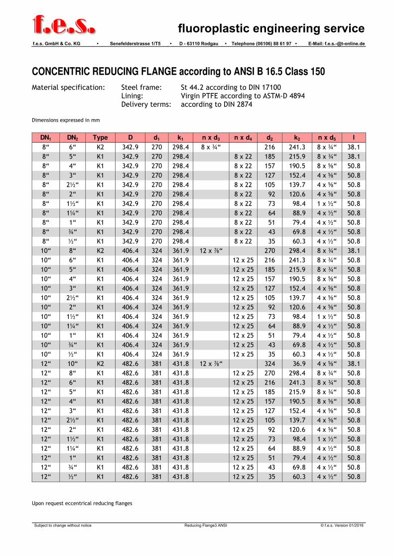
CONCENTRIC REDUCING FLANGE according to ANSI B 16.5 Class 150
Material specification: Steel frame: St 44.2 according to DIN 17100 Lining: Virgin PTFE according to ASTM-D 4894 Delivery terms: according to DIN 2874
Dimensions expressed in mm
DN1
2
DN1
DN2
DN1
DN2
d 5>
d>
5 d>
5
d4
L L L
d
d
k
d
k
D
DN
2
2
1
1
5 d 5
2
2
d
k
D
k
d
1
1
3d
d 5
2
2
d
k
D
k
d
1
1
3d
A B
B
A
C
C
Form K1 Form K2 Form K3
SECTION A - A SECTION B - B SECTION C - C
DN1 DN2 Type D d1 k1 n x d3 n x d4 d2 k2 n x d5 l
¾“ ½“ K3 98.4 43 69.7 4 x ½“ 35 60.3 4 x ½“ 38.1
1“ ¾“ K3 107.9 51 79.4 4 x ½“ 43 69.8 4 x ½“ 38.1
1“ ½“ K3 107.9 51 79.4 4 x ½“ 35 60.3 4 x ½“ 38.1
1¼“ 1“ K3 117.5 64 88.9 4 x ½“ 51 79.4 4 x ½“ 38.1
1¼“ ¾“ K3 117.5 64 88.9 4 x ½“ 43 69.8 4 x ½“ 38.1
1¼“ ½“ K3 117.5 64 88.9 4 x ½“ 35 60.3 4 x ½“ 38.1
1½“ 1¼“ K3 127.0 73 98.4 4 x ½“ 64 88.9 4 x ½“ 38.1
1½“ 1“ K3 127.0 73 98.4 4 x ½“ 51 79.4 4 x ½“ 38.1
1½“ ¾“ K2 127.0 73 98.4 4 x ½“ 43 69.8 4 x ½“ 38.1
1½“ ½“ K2 127.0 73 98.4 4 x ½“ 35 60.3 4 x ½“ 38.1
2“ 1½“ K3 152.4 92 120.6 4 x “ 73 98.4 1 x ½“ 38.1
2“ 1¼“ K3 152.4 92 120.6 4 x “ 64 88.9 4 x ½“ 38.1
2“ 1“ K2 152.4 92 120.6 4 x “ 51 79.4 4 x ½“ 38.1
2“ ¾“ K2 152.4 92 120.6 4 x “ 43 69.8 4 x ½“ 38.1
2“ ½“ K2 152.4 92 120.6 4 x “ 35 60.3 4 x ½“ 38.1
Subject to change without notice Reducing Flange1 ANSI © f.e.s. Version 01/2016

f.e.s.
fluoroplastic engineering servicef.e.s. GmbH & Co. KG • Senefelderstrasse 1/T5 • D - 63110 Rodgau • Telephone (06106) 88 61 97 • E-Mail: [email protected]
CONCENTRIC REDUCING FLANGE according to ANSI B 16.5 Class 150
Material specification: Steel frame: St 44.2 according to DIN 17100 Lining: Virgin PTFE according to ASTM-D 4894 Delivery terms: according to DIN 2874 Dimensions expressed in mm
DN1 DN2 Type D d1 k1 n x d3 n x d4 d2 k2 n x d5 l
2½“ 2“ K3 177.8 105 139.7 4 x “ 92 120.6 4 x “ 38.1
2½“ 1½“ K3 177.8 105 139.7 4 x “ 73 98.4 1 x ½“ 38.1
2½“ 1¼“ K2 177.8 105 139.7 4 x “ 64 88.9 4 x ½“ 38.1
2½“ 1“ K2 177.8 105 139.7 4 x “ 51 79.4 4 x ½“ 38.1
2½“ ¾“ K2 177.8 105 139.7 4 x “ 43 69.8 4 x ½“ 38.1
2½“ ½“ K2 177.8 105 139.7 4 x “ 35 60.3 4 x ½“ 38.1
3“ 2½“ K2 190.5 127 152.4 4 x “ 105 139.7 4 x “ 38.1
3“ 2“ K2 190.5 127 152.4 4 x “ 92 120.6 4 x “ 38.1
3“ 1½“ K2 190.5 127 152.4 4 x “ 73 98.4 1 x ½“ 38.1
3“ 1¼“ K2 190.5 127 152.4 4 x “ 64 88.9 4 x ½“ 38.1
3“ 1“ K1 190.5 127 152.4 4 x 19 51 79.4 4 x ½“ 38.1
3“ ¾“ K1 190.5 127 152.4 4 x 19 43 69.8 4 x ½“ 38.1
3“ ½“ K1 190.5 127 152.4 4 X 19 35 60.3 4 x ½“ 38.1
4“ 3“ K3 228.6 157 190.5 8 x “ 127 152.4 4 x “ 38.1
4“ 2½“ K2 228.6 157 190.5 8 x “ 105 139.7 4 x “ 38.1
4“ 2“ K2 228.6 157 190.5 8 x “ 92 120.6 4 x “ 38.1
4“ 1½“ K1 228.6 157 190.5 8 x 19 73 98.4 1 x ½“ 50.8
4“ 1¼“ K1 228.6 157 190.5 8 x 19 64 88.9 4 x ½“ 50.8
4“ 1“ K1 228.6 157 190.5 8 x 19 51 79.4 4 x ½“ 50.8
4“ ¾“ K1 228.6 157 190.5 8 x 19 43 69.8 4 x ½“ 50.8
4“ ½“ K1 228.6 157 190.5 8 x 19 35 60.3 4 x ½“ 50.8
5“ 4“ K3 254.0 185 215.9 8 x ¾“ 157 190.5 8 x “ 38.1
5“ 3“ K2 254.0 185 215.9 8 x ¾“ 127 152.4 4 x “ 38.1
5“ 2½“ K2 254.0 185 215.9 8 x ¾“ 105 139.7 4 x “ 50.8
5“ 2“ K1 254.0 185 215.9 8 x 22 92 120.6 4 x “ 50.8
5“ 1½“ K1 254.0 185 215.9 8 x 22 73 98.4 1 x ½“ 50.8
5“ 1¼“ K1 254.0 185 215.9 8 x 22 64 88.9 4 x ½“ 50.8
5“ 1“ K1 254.0 185 215.9 8 x 22 51 79.4 4 x ½“ 50.8
5“ ¾“ K1 254.0 185 215.9 8 x 22 43 69.8 4 x ½“ 50.8
5“ ½“ K1 254.0 185 215.9 8 x 22 35 60.3 4 x ½“ 50.8
6“ 5“ K3 279.4 216 241.3 8 x ¾“ 185 215.9 8 x ¾“ 38.1
6“ 4“ K2 279.4 216 241.3 8 x ¾“ 157 190.5 8 x “ 38.1
6“ 3“ K1 279.4 216 241.3 8 x 22 127 152.4 4 x “ 50.8
6“ 2½“ K1 279.4 216 241.3 8 x 22 105 139.7 4 x “ 50.8
6“ 2“ K1 279.4 216 241.3 8 x 22 92 120.6 4 x “ 50.8
6“ 1½“ K1 279.4 216 241.3 8 x 22 73 98.4 1 x ½“ 50.8
6“ 1¼“ K1 279.4 216 241.3 8 x 22 64 88.9 4 x ½“ 50.8
6“ 1“ K1 279.4 216 241.3 8 x 22 51 79.4 4 x ½“ 50.8
6“ ¾“ K1 279.4 216 241.3 8 x 22 43 69.8 4 x ½“ 50.8
6“ ½“ K1 279.4 216 241.3 8 x 22 35 60.3 4 x ½“ 50.8
Subject to change without notice Reducing Flange 2 ANSI © f.e.s. Version 01/2016
f.e.s.
fluoroplastic engineering servicef.e.s. GmbH & Co. KG • Senefelderstrasse 1/T5 • D - 63110 Rodgau • Telephone (06106) 88 61 97 • E-Mail: [email protected]
CONCENTRIC REDUCING FLANGE according to ANSI B 16.5 Class 150
Material specification: Steel frame: St 44.2 according to DIN 17100 Lining: Virgin PTFE according to ASTM-D 4894 Delivery terms: according to DIN 2874 Dimensions expressed in mm
DN1 DN2 Type D d1 k1 n x d3 n x d4 d2 k2 n x d5 l
8“ 6“ K2 342.9 270 298.4 8 x ¾“ 216 241.3 8 x ¾“ 38.1
8“ 5“ K1 342.9 270 298.4 8 x 22 185 215.9 8 x ¾“ 38.1
8“ 4“ K1 342.9 270 298.4 8 x 22 157 190.5 8 x “ 50.8
8“ 3“ K1 342.9 270 298.4 8 x 22 127 152.4 4 x “ 50.8
8“ 2½“ K1 342.9 270 298.4 8 x 22 105 139.7 4 x “ 50.8
8“ 2“ K1 342.9 270 298.4 8 x 22 92 120.6 4 x “ 50.8
8“ 1½“ K1 342.9 270 298.4 8 x 22 73 98.4 1 x ½“ 50.8
8“ 1¼“ K1 342.9 270 298.4 8 x 22 64 88.9 4 x ½“ 50.8
8“ 1“ K1 342.9 270 298.4 8 x 22 51 79.4 4 x ½“ 50.8
8“ ¾“ K1 342.9 270 298.4 8 x 22 43 69.8 4 x ½“ 50.8
8“ ½“ K1 342.9 270 298.4 8 x 22 35 60.3 4 x ½“ 50.8
10“ 8“ K2 406.4 324 361.9 12 x “ 270 298.4 8 x ¾“ 38.1
10“ 6“ K1 406.4 324 361.9 12 x 25 216 241.3 8 x ¾“ 50.8
10“ 5“ K1 406.4 324 361.9 12 x 25 185 215.9 8 x ¾“ 50.8
10“ 4“ K1 406.4 324 361.9 12 x 25 157 190.5 8 x “ 50.8
10“ 3“ K1 406.4 324 361.9 12 x 25 127 152.4 4 x “ 50.8
10“ 2½“ K1 406.4 324 361.9 12 x 25 105 139.7 4 x “ 50.8
10“ 2“ K1 406.4 324 361.9 12 x 25 92 120.6 4 x “ 50.8
10“ 1½“ K1 406.4 324 361.9 12 x 25 73 98.4 1 x ½“ 50.8
10“ 1¼“ K1 406.4 324 361.9 12 x 25 64 88.9 4 x ½“ 50.8
10“ 1“ K1 406.4 324 361.9 12 x 25 51 79.4 4 x ½“ 50.8
10“ ¾“ K1 406.4 324 361.9 12 x 25 43 69.8 4 x ½“ 50.8
10“ ½“ K1 406.4 324 361.9 12 x 25 35 60.3 4 x ½“ 50.8
12“ 10“ K2 482.6 381 431.8 12 x “ 324 36.9 4 x “ 38.1
12“ 8“ K1 482.6 381 431.8 12 x 25 270 298.4 8 x ¾“ 50.8
12“ 6“ K1 482.6 381 431.8 12 x 25 216 241.3 8 x ¾“ 50.8
12“ 5“ K1 482.6 381 431.8 12 x 25 185 215.9 8 x ¾“ 50.8
12“ 4“ K1 482.6 381 431.8 12 x 25 157 190.5 8 x “ 50.8
12“ 3“ K1 482.6 381 431.8 12 x 25 127 152.4 4 x “ 50.8
12“ 2½“ K1 482.6 381 431.8 12 x 25 105 139.7 4 x “ 50.8
12“ 2“ K1 482.6 381 431.8 12 x 25 92 120.6 4 x “ 50.8
12“ 1½“ K1 482.6 381 431.8 12 x 25 73 98.4 1 x ½“ 50.8
12“ 1¼“ K1 482.6 381 431.8 12 x 25 64 88.9 4 x ½“ 50.8
12“ 1“ K1 482.6 381 431.8 12 x 25 51 79.4 4 x ½“ 50.8
12“ ¾“ K1 482.6 381 431.8 12 x 25 43 69.8 4 x ½“ 50.8
12“ ½“ K1 482.6 381 431.8 12 x 25 35 60.3 4 x ½“ 50.8
Upon request eccentrical reducing flanges
Subject to change without notice Reducing Flange3 ANSI © f.e.s. Version 01/2016

f.e.s.
fluoroplastic engineering servicef.e.s. GmbH & Co. KG • Senefelderstrasse 1/T5 • D - 63110 Rodgau • Telephone (06106) 88 61 97 • E-Mail: [email protected]
BLIND FLANGE according to ANSI B 16.5 Class 150
Mat erial specif icat ion: Flange: ASTM A 105 according t o ANSI B 16.5
Lining: Virgin PTFE according t o ASTM-D 4894
Del ivery t erms: according t o DIN 2874
Dimensions expressed in mm
d
k
D
s4
DN s d4 k D
½“ 3 35 60.3 88.9
¾ 3 43 69.8 98.4
1“ 3 51 79.4 107.9
1¼“ 3 64 88.9 117.5
1½“ 3 73 98.4 127.0
2“ 3 92 120.6 152.4
2½“ 3.5 105 139.7 177.8
3“ 4 127 152.4 190.5
4“ 4.5 157 190.5 228.6
5“ 4.5 185 215.9 254.0
6“ 5 216 241.3 279.4
8“ 6 270 298.4 342.9
10“ 7 324 361.9 406.4
12” 7 381 431.8 482.6
Subject to change without notice Blind Flange ANSI © f.e.s. Version 01/2016

f.e.s. fluoroplastic engineering service
f.e.s. GmbH & Co. KG • Senefelderstrasse 1/T5 • D - 63110 Rodgau • Telephone (06106) 88 61 97 • E-Mail: [email protected]
SPACERS and ARMORED SPACERS according to ANSI B 16.5 Class 150
Mat erial specif icat ion: Form F: Virgin PTFE according t o ASTM-D 4894
Form G + H: ASTM A 106 Grade B according t o ANSI B 36.10
API 5L Grade B according t o ANSI B 36.10
ASTM A 105 according t o ANSI B 36.10
St 52.0 according t o DIN 1629
Del ivery t erms: according t o DIN 2874
Dimensions expressed in mm
l l l
dd 15 1d 1ddd 45 5 4d d
Form F Form G Form H
s ss f
DN d1 ss s d4 d5 l (Form F) l (Form G) l (Form H)
½“ 9 3.00 3 35 44
¾“ 15 3.00 3 43 53
1“ 19 3.38 3 51 63
1¼“ 28 3.56 3 64 72
½“ 32 3.68 3 73 82
2“ 44 3.91 3 92 101
2½“ 61 5.16 3.5 105 119 5 - 20 10 - 70 60 - 100
3“ 69 5.49 4 127 132
4“ 94 6.02 4.5 157 171
5“ 121 6.55 4.5 186 192
6“ 144 7.11 5 216 218
8“ 194 6.35 6 270 275
10“ 246 6.35 7 324 337
12” 297 6.35 7 381 406
Subject to change without notice Spacers ANSI © f.e.s. Version 01/2016

f.e.s.
fluoroplastic engineering servicef.e.s. GmbH & Co. KG • Senefelderstrasse 1/T5 • D - 63110 Rodgau • Telephone (06106) 88 61 97 • E-Mail: [email protected]
INSTRUMENT TAPPING according to ANSI B 16.5 Class 150
Mat erial specif icat ion: St eel f rame: ASTM A 106 Grade B according t o ANSI B 36.10
API 5L Grade B according t o ANSI B 36.10
St 52.0 according t o DIN 1629
Flanges: A 105 Grade B according t o ANSI B 16.5
Lining: Virgin PTFE according t o ASTM-D 4894
Del ivery t erms: according t o DIN 2874
Dimensions expressed in mm
s
d
d
l
4
5
2
DN1
DN2
Main passage Branch DN2
DN1 s d4 d5 l1
1“
l2
1½“
l2
2“
l2
1“ 3 51 63 89 51 75 90
1¼“ 3 64 72 95 51 75 90
1½“ 3 73 82 102 51 75 90
2“ 3 92 101 114 51 75 90
2½“ 3.5 105 119 127 51 75 90
3“ 4 127 132 140 51 75 90
4“ 4.5 157 171 165 51 75 90
5“ 4.5 186 192 190 51 75 90
6“ 5 216 218 203 51 75 90
8“ 6 270 275 229 51 75 90
10“ 7 324 337 279 51 75 90
12” 7 381 406 305 51 75 90
Upon request furt her dimensions available
On demand inst rument t appings wit h double, t r iple and quadruple branches available
Vent holes upon operat or’ s request
Subject to change without notice Instrument Tappings ANSI 150 © f.e.s. Version 01/2016