stepper motors - farnell element14 · saia® motors 155 1.937.454.2345 fax: 1.937.898.8624...
TRANSCRIPT

Saia® Motors www.saia-motor-usa.com 1.937.454.2345 Fax: 1.937.898.8624155
Dimensions
Circuit diagramTrave l
Pull (in)
Push (out)
StepperMotors
Linear
Dimensions
Circuit diagram
Saia® Motors www.saia-motor-usa.com 1.937.454.2345 Fax: 1.937.898.8624156
UCE
Stepper Motor UCE 13 N 24 Ω B 1A
13 bipolar, standard magnet 73 bipolar, stronger magnet23 unipolar, standard magnet 83 unipolar, stronger magnet
N
see next page, Resistance per winding for bipolar or unipolar
C see next pages „Connection Types“D
1A Travel 10 mm ± 0,7 mm1B Travel 13 mm ± 0,7 mm
Dimensions (mm)
Travel (mm)
Travel per step (mm)
Thread pitch (mm)
Speed (mm/s) at 200 Hz
Step angle (°)
Max. Force (N)*
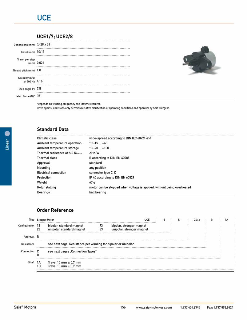
UCE1/7; UCE2/8∅ 28 x 31
10/13
0,021
1,0
4,16
7,5
35
*Depends on winding, frequency and lifetime required. Drive against end stops only permissible after clarification of operating conditions and approval by Saia-Burgess.
Standard Data
Climatic class wide-spread according to DIN IEC 60721-2-1Ambient temperature operation °C -15 ... +60 Ambient temperature storage °C -20 ... +100Thermal resistance at f=0 Rtherm 29 K/W Thermal class B according to DIN EN 60085Approval standardMounting any positionElectrical connection connector type C, DProtection IP 40 according to DIN EN 60529Weight 67 g Rotor stalling motor can be stopped when voltage is applied, without being overheatedBearings ball bearing
Type
Configuration Approval
Resistance
Connection
Shaft
Order Reference
Line
ar
Saia® Motors www.saia-motor-usa.com 1.937.454.2345 Fax: 1.937.898.8624157
Linear
UCE
Technical Data
bipolar type UCE1 UCE1 UCE5 UCE5 Operating frequency Hz 100 200 100 200 max. Push/Pull force * 30% duty cycle N 49 42 50 50 100% duty cycle N 42 28 49 39
unipolar type UCE2 UCE2 UCE6 UCE6 Operating frequency Hz 100 200 100 200 max. Push/Pull force * 30% duty cycle N 35 28 49 39 100% duty cycle N 21 17 29 23
Rated voltage UN: V 6 12 24 Resistance per winding R20 Ω 24 90 380 Steps per mm 48 Duty cycle 100 % Winding temperature Tmax °C 130 Linear travel max. mm 10/13 Axial play at ± 20 N force mm < 0,25 * measured at 23 °C, lifetime depends on load characteristics and ambient conditions
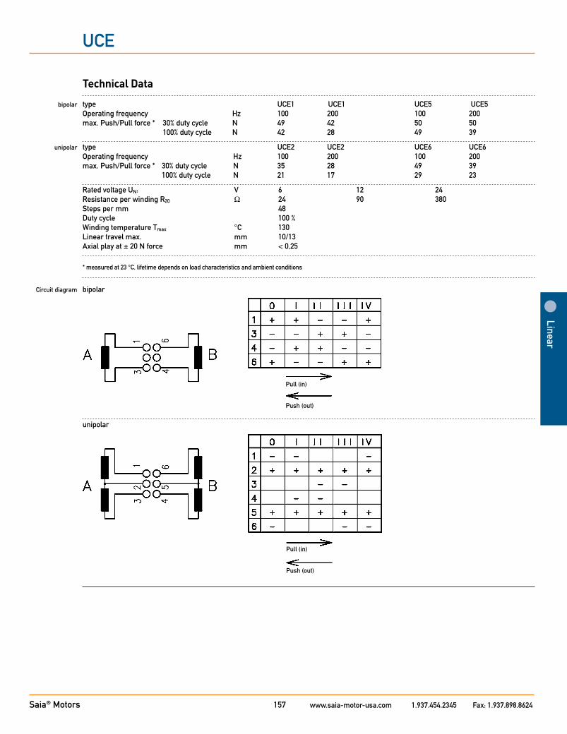
Circuit diagram bipolar
unipolar
Pull (in)
Push (out)
Pull (in)
Push (out)
Saia® Motors www.saia-motor-usa.com 1.937.454.2345 Fax: 1.937.898.8624158
UCE
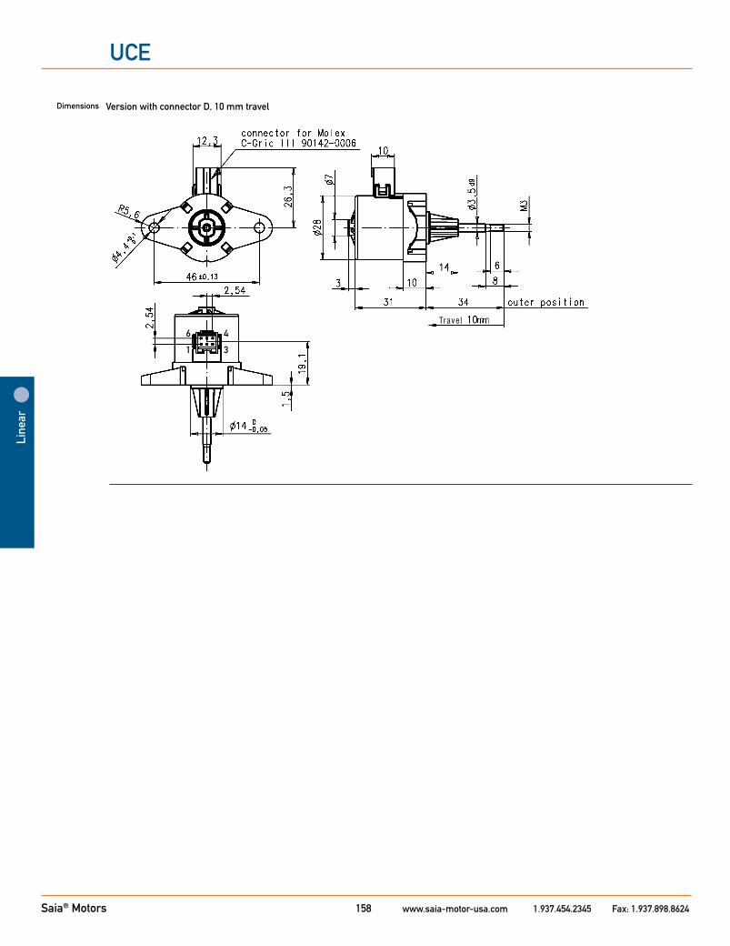
Version with connector D, 10 mm travelDimensions
Trave l
Line
ar
6
1
4
3
Saia® Motors www.saia-motor-usa.com 1.937.454.2345 Fax: 1.937.898.8624159
Linear
UCL
Stepper Motor UCL 13 N 24 Ω B 1A
13 bipolar, standard magnet 73 bipolar, stronger magnet23 unipolar, standard magnet 83 unipolar, stronger magnet
N
see next page, Resistance per winding for bipolar or unipolar
C see next pages „Connection Types“D
1A Travel 10 mm ± 0,7 mm1B Travel 13 mm ± 0,7 mm
Dimensions (mm)
Travel (mm)
Travel per step (mm)
Thread pitch (mm)
Speed (mm/s) at 200 Hz
Step angle (°)
Max. Force (N)*
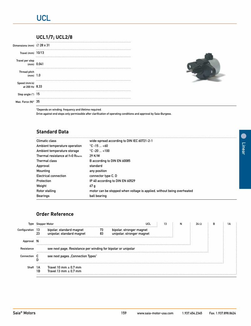
UCL1/7; UCL2/8∅ 28 x 31
10/13
0,041
1,0
8,33
15
35
*Depends on winding, frequency and lifetime required. Drive against end stops only permissible after clarification of operating conditions and approval by Saia-Burgess.
Standard Data
Climatic class wide-spread according to DIN IEC 60721-2-1Ambient temperature operation °C -15 ... +60 Ambient temperature storage °C -20 ... +100Thermal resistance at f=0 Rtherm 29 K/W Thermal class B according to DIN EN 60085Approval standardMounting any positionElectrical connection connector type C, DProtection IP 40 according to DIN EN 60529Weight 67 g Rotor stalling motor can be stopped when voltage is applied, without being overheatedBearings ball bearing
Type
Configuration Approval
Resistance
Connection
Shaft
Order Reference

Saia® Motors www.saia-motor-usa.com 1.937.454.2345 Fax: 1.937.898.8624160
UCL
Technical Data
bipolar type UCL1 UCL1 UCL5 UCL5 Operating frequency Hz 100 200 100 200 max. Push/Pull force * 30% ED N 35 30 50 45 100% ED N 30 20 35 28
unipolar type UCL2 UCL2 UCL6 UCL6 Operating frequency Hz 100 200 100 200 max. Push/Pull force * 30% ED N 25 20 35 28 100% ED N 15 12 21 17
Rated voltage UN: V 6 12 24 Resistance per winding R20 Ω 24 90 380 Steps per mm 24 Duty cycle 100 % Winding temperature Tmax °C 130 Linear travel max. mm 10/13 Axial play at ± 20 N force mm < 0,25 * measured at 23 °C, lifetime depends on load characteristics and ambient conditions
Circuit diagram bipolar
unipolar
Pull (in)
Push (out)
Pull (in)
Push (out)
Line
ar
Saia® Motors www.saia-motor-usa.com 1.937.454.2345 Fax: 1.937.898.8624161
Linear
UCL
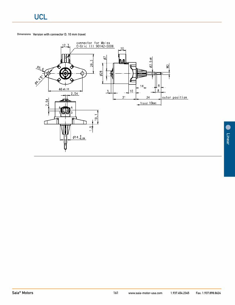
Version with connector D, 10 mm travelDimensions
Trave l
6
1
4
3
Saia® Motors www.saia-motor-usa.com 1.937.454.2345 Fax: 1.937.898.8624162
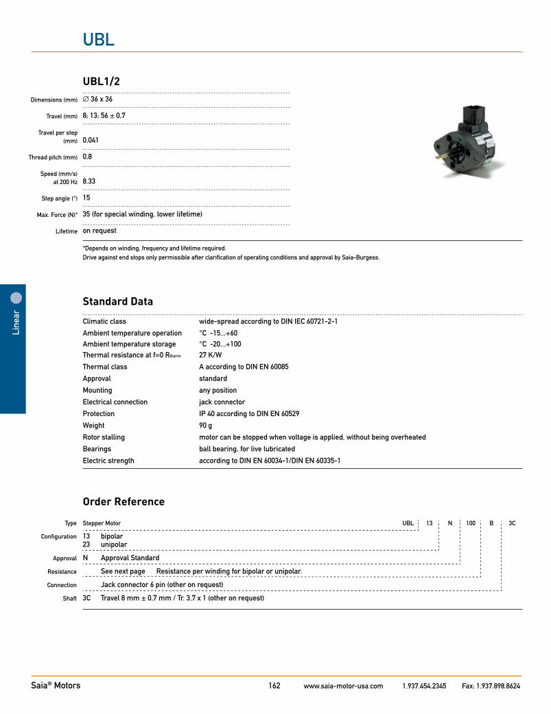
UBL
Dimensions (mm)
Travel (mm)
Travel per step (mm)
Thread pitch (mm)
Speed (mm/s) at 200 Hz
Step angle (°)
Max. Force (N)*
Lifetime
UBL1/2∅ 36 x 36
8; 13; 56 ± 0,7
0,041
0,8
8.33
15
35 (for special winding, lower lifetime)
on request
*Depends on winding, frequency and lifetime required. Drive against end stops only permissible after clarification of operating conditions and approval by Saia-Burgess.
Standard Data
Climatic class wide-spread according to DIN IEC 60721-2-1
Ambient temperature operation °C -15...+60 Ambient temperature storage °C -20...+100 Thermal resistance at f=0 Rtherm 27 K/W
Thermal class A according to DIN EN 60085
Approval standard
Mounting any position
Electrical connection jack connector
Protection IP 40 according to DIN EN 60529
Weight 90 g
Rotor stalling motor can be stopped when voltage is applied, without being overheated
Bearings ball bearing, for live lubricated
Electric strength according to DIN EN 60034-1/DIN EN 60335-1
Type
Configuration
Approval
Resistance
Connection
Shaft
Stepper Motor UBL 13 N 100 B 3C
13 bipolar 23 unipolar
N Approval Standard
See next page Resistance per winding for bipolar or unipolar.
Jack connector 6 pin (other on request)
3C Travel 8 mm ± 0,7 mm / Tr. 3,7 x 1 (other on request)
Order Reference
Line
ar
Saia® Motors www.saia-motor-usa.com 1.937.454.2345 Fax: 1.937.898.8624163
Linear
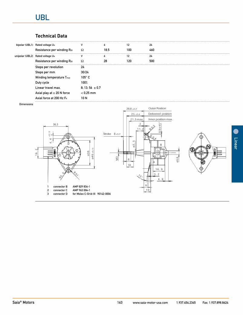
UBL
Technical Data
bipolar (UBL1) Rated voltage UN V 6 12 24
Resistance per winding R20 Ω 18,5 100 460
unipolar (UBL2) Rated voltage UN V 6 12 24
Resistance per winding R20 Ω 28 120 500
Steps per revolution 24
Steps per mm 30/24
Winding temperature Tmax 105° C
Duty cycle 100%
Linear travel max. 8; 13; 56 ± 0,7
Axial play at ± 20 N force < 0,25 mm
Axial force at 200 Hz FA 10 N
Dimensions
1 connector B AMP 829 836-12 connector C AMP 963 004-13 connector D for Molex C-Grid-III 90142-0006
Saia® Motors www.saia-motor-usa.com 1.937.454.2345 Fax: 1.937.898.8624164
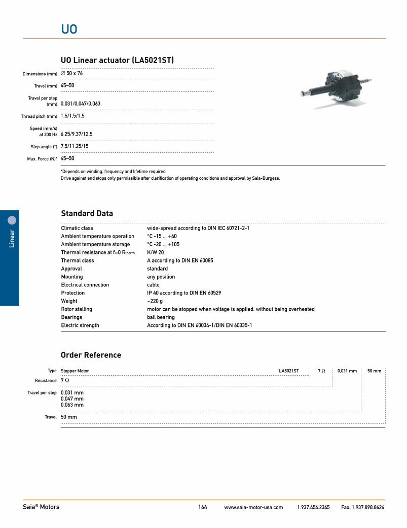
UO
Stepper Motor LA5021ST 7 Ω 0,031 mm 50 mm
7 Ω
0,031 mm0,047 mm0,063 mm
50 mm
Dimensions (mm)
Travel (mm)
Travel per step (mm)
Thread pitch (mm)
Speed (mm/s) at 200 Hz
Step angle (°)
Max. Force (N)*
UO Linear actuator (LA5021ST)∅ 50 x 76
45–50
0,031/0,047/0,063
1,5/1,5/1,5
6,25/9,37/12,5
7,5/11,25/15
45–50
*Depends on winding, frequency and lifetime required. Drive against end stops only permissible after clarification of operating conditions and approval by Saia-Burgess.
Standard Data
Climatic class wide-spread according to DIN IEC 60721-2-1Ambient temperature operation °C -15 ... +40 Ambient temperature storage °C -20 ... +105Thermal resistance at f=0 Rtherm K/W 20 Thermal class A according to DIN EN 60085Approval standardMounting any positionElectrical connection cableProtection IP 40 according to DIN EN 60529Weight ~220 g Rotor stalling motor can be stopped when voltage is applied, without being overheatedBearings ball bearingElectric strength According to DIN EN 60034-1/DIN EN 60335-1
Type
Resistance Travel per step
Travel
Order Reference
Line
ar
Saia® Motors www.saia-motor-usa.com 1.937.454.2345 Fax: 1.937.898.8624165
Linear
UO
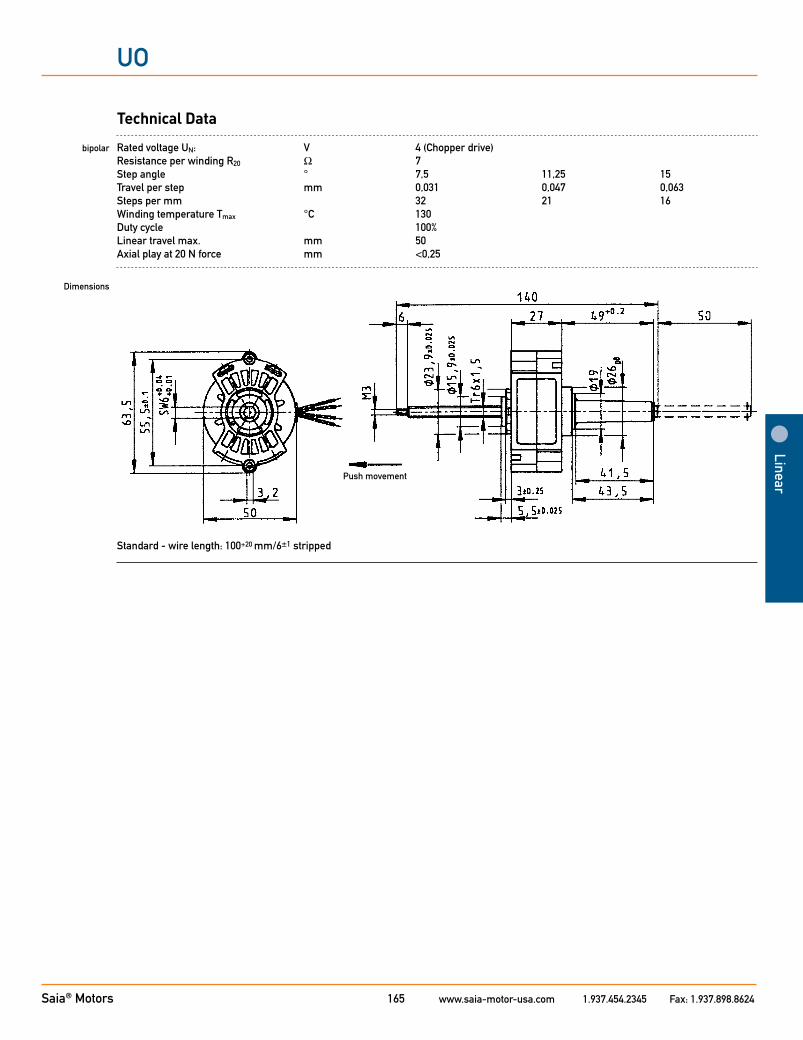
Technical Data
bipolar Rated voltage UN: V 4 (Chopper drive) Resistance per winding R20 Ω 7 Step angle ° 7,5 11,25 15 Travel per step mm 0,031 0,047 0,063 Steps per mm 32 21 16 Winding temperature Tmax °C 130 Duty cycle 100% Linear travel max. mm 50 Axial play at 20 N force mm <0,25 Dimensions
Push movement
Standard - wire length: 100+20 mm/6±1 stripped
Saia® Motors www.saia-motor-usa.com 1.937.454.2345 Fax: 1.937.898.8624166
UO
Stepper Motor SP5022ST 7 Ω 0,031 mm 68 mm
7 Ω
0,031 mm0,047 mm0,063 mm
68 mm130 mm
Dimensions (mm)
Travel (mm)
Travel per step (mm)
Thread pitch (mm)
Speed (mm/s) at 200 Hz
Step angle (°)
Max. Force (N)*
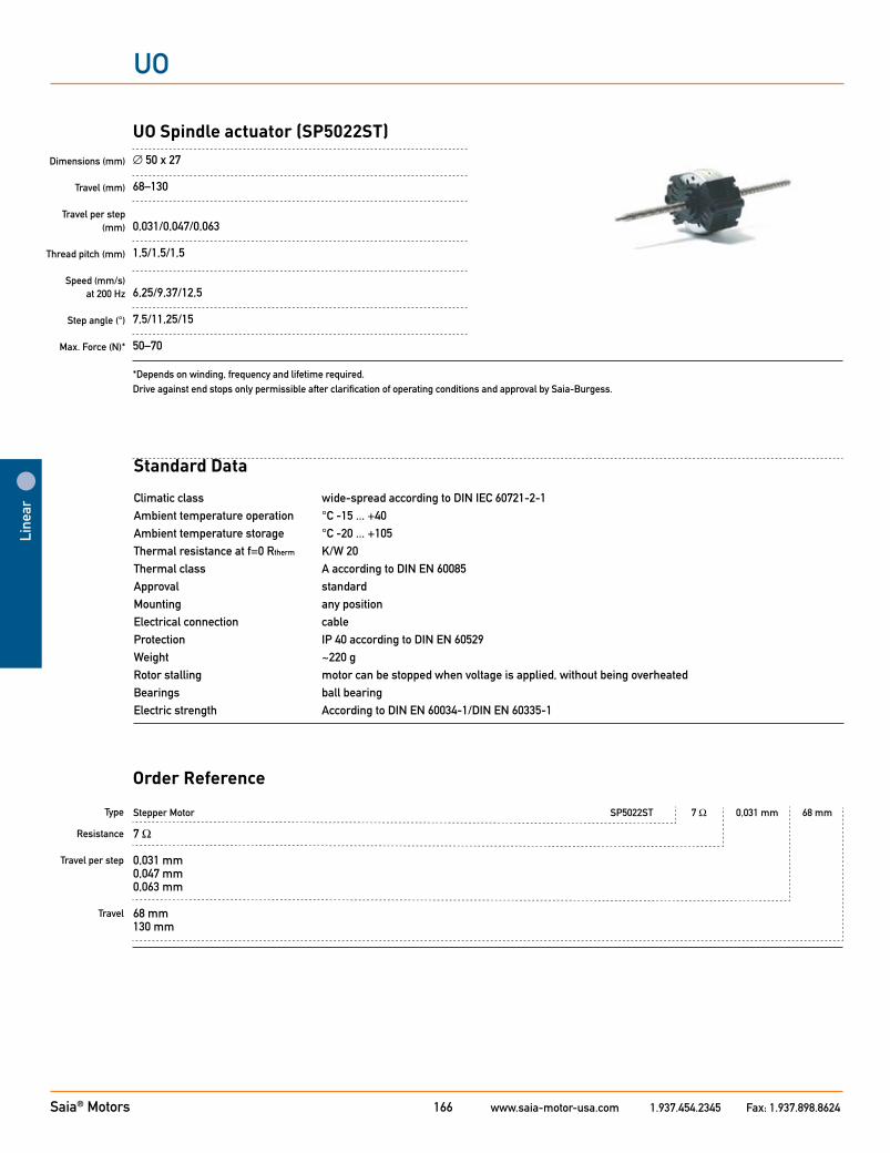
UO Spindle actuator (SP5022ST)∅ 50 x 27
68–130
0,031/0,047/0,063
1,5/1,5/1,5
6,25/9,37/12,5
7,5/11,25/15
50–70
*Depends on winding, frequency and lifetime required. Drive against end stops only permissible after clarification of operating conditions and approval by Saia-Burgess.
Standard Data
Climatic class wide-spread according to DIN IEC 60721-2-1Ambient temperature operation °C -15 ... +40 Ambient temperature storage °C -20 ... +105Thermal resistance at f=0 Rtherm K/W 20 Thermal class A according to DIN EN 60085Approval standardMounting any positionElectrical connection cableProtection IP 40 according to DIN EN 60529Weight ~220 g Rotor stalling motor can be stopped when voltage is applied, without being overheatedBearings ball bearingElectric strength According to DIN EN 60034-1/DIN EN 60335-1
Type
Resistance Travel per step
Travel
Order Reference
Line
ar
Saia® Motors www.saia-motor-usa.com 1.937.454.2345 Fax: 1.937.898.8624167
Linear
UO
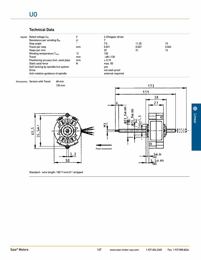
Technical Data
bipolar Rated voltage UN: V 4 (Chopper drive) Resistance per winding R20 Ω 7 Step angle ° 7,5 11,25 15 Travel per step mm 0,031 0,047 0,063 Steps per mm 32 21 16 Winding temperature Tmax °C 130 Travel mm ~68/+130 Positioning accuacy (incl. axial play) mm ± 0,15 Static axial force N max. 50 Self-locking by spindle/nut system yes Drive not stall-proof Anti-rotation guidance of spindle external required
Dimensions Version with Travel 68 mm 130 mm
Push movement
Standard - wire length: 100+20 mm/6±1 stripped
Saia® Motors www.saia-motor-usa.com 1.937.454.2345 Fax: 1.937.898.8624Addendum 1
Linear
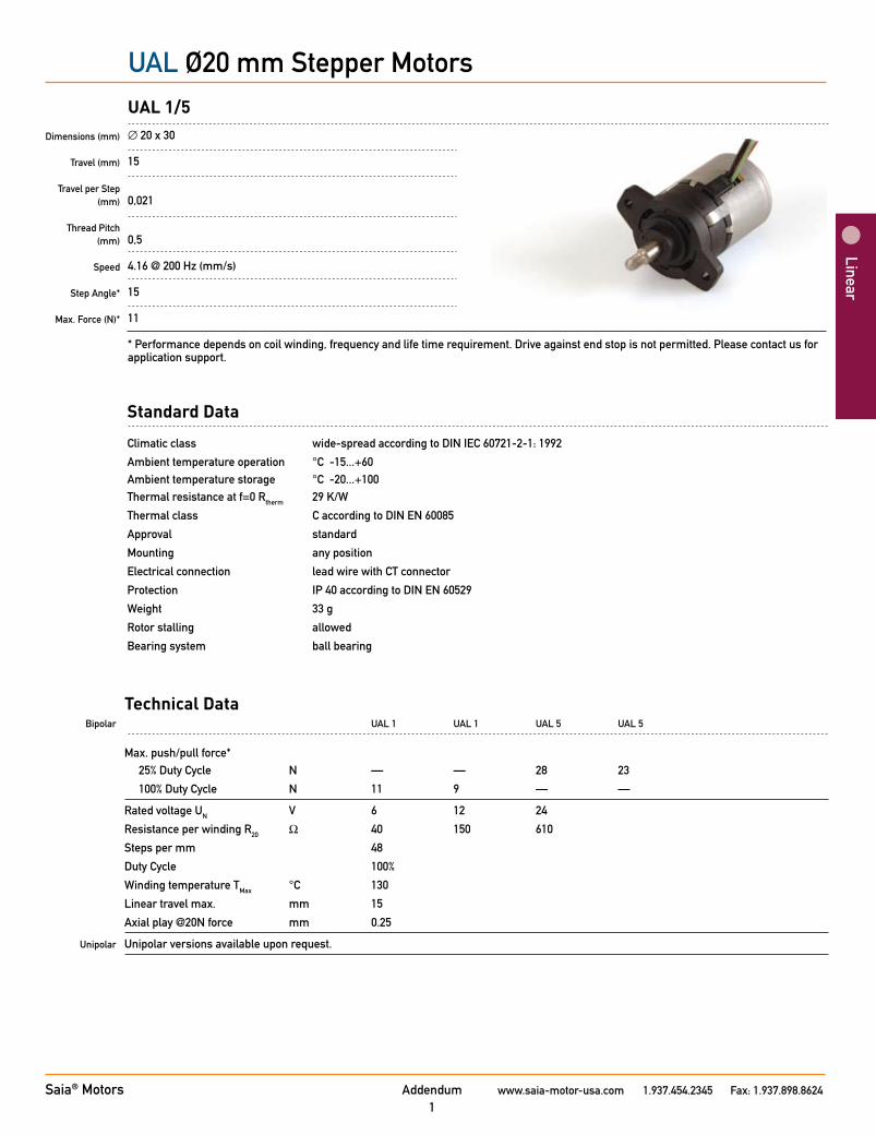
UAL Ø20 mm Stepper Motors
Dimensions (mm)
Travel (mm)
Travel per Step (mm)
Thread Pitch (mm)
Speed
Step Angle*
Max. Force (N)*
UAL 1/5∅ 20 x 30
15
0,021
0,5
4.16 @ 200 Hz (mm/s)
15
11
* Performance depends on coil winding, frequency and life time requirement. Drive against end stop is not permitted. Please contact us for application support.
Standard Data
Climatic class wide-spread according to DIN IEC 60721-2-1: 1992
Ambient temperature operation °C -15...+60 Ambient temperature storage °C -20...+100 Thermal resistance at f=0 Rtherm 29 K/W
Thermal class C according to DIN EN 60085
Approval standard
Mounting any position
Electrical connection lead wire with CT connector
Protection IP 40 according to DIN EN 60529
Weight 33 g
Rotor stalling allowed
Bearing system ball bearing
Technical Data Bipolar UAL 1 UAL 1 UAL 5 UAL 5
Max. push/pull force* 25% Duty Cycle N — — 28 23
100% Duty Cycle N 11 9 — —
Rated voltage UN V 6 12 24
Resistance per winding R20 Ω 40 150 610
Steps per mm 48
Duty Cycle 100%
Winding temperature TMax °C 130
Linear travel max. mm 15
Axial play @20N force mm 0.25
Unipolar Unipolar versions available upon request.
Technical Data
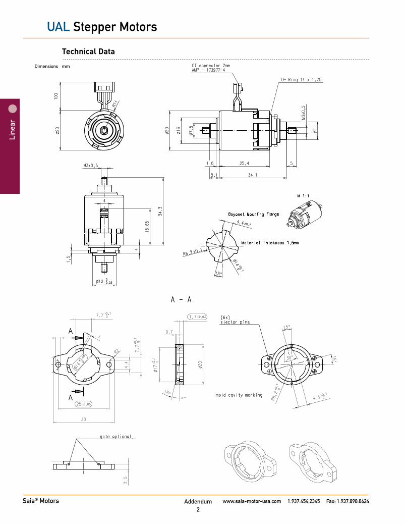
Dimensions mm
Addendum 2
Line
ar
UAL Stepper Motors
Saia® Motors www.saia-motor-usa.com 1.937.454.2345 Fax: 1.937.898.8624

Stepper Motor UAL 13 N 150 (Ω) E 1B
13 bipolar, standard magnet 53 bipolar, stronger magnet
N Approval Standard
Resistance per winding (see previous page)
C 100 mm lead wire with CT connector
1B Travel 15 mm ±0.7 mm (others upon request)
Type
Configuration
Approval
Resistance
Connection
Shaft
Order Reference
Technical Data
Circuit Diagram
Dimensions mm
Saia® Motors www.saia-motor-usa.com 1.937.454.2345 Fax: 1.937.898.8624Addendum3
UAL Stepper Motors

Features and Benefits•Constantpositioningforceoverfulltravel•Compactdesignenvelope•NEMA23mountingflange•Flexibledesigntoaccommodatemanycustom
requirements
Functional Advantages•Unipolarorbipolar•Positionforceto400N•Strokesto300mm•Flexiblemounting
Linear Stepper MotorsIntroducing: Advanced Performance Saia® ULE Series Linear Stepper Motors
Markets/Applications•Valvecontrols•Positioningand
adjustmentsystems•Handlingsystemsfor
theautomationindustry
Saia® Motors www.saia-motor-usa.com 1.937.454.2345 Fax: 1.937.898.8624
Circuit Diagram
Pull (in)
Push (out)
Bipolar
Unipolar
Pull (in)
Push (out)
Pull (in)
Push (out)
Bipolar
Unipolar
Pull (in)
Push (out)
Technical Data*
General Performance/Mechanical Data
Dimensions mm Ø55 x 55Linear Travel Max mm Up to 300 (longer travels available upon request)Linear Travel Standard mm 10Travel per Step mm 0,031Thread Pitch mm 1,5Speed mm/s 6.25 @ 200 HzStep Angle** ° 7.5Steps per mm 32Bearing System ball bearingDuty Cycle 25% ... 100%Max. Force** N 400Axial Play @ 20 N Force 0.3Max. Push/Pull Force* 25% Duty Cycle N 400 100% Duty Cycle N 205
Electrical
Rated Voltage UN V 24 Resistance per Winding R20 ULE 1 Ω 100Winding Temperature TMax °C 155Thermal Resistance at f=0 Rtherm K/W 8.7Electrical Connection lead wire (connectors available upon request)
*Data based on Bipolar models. Unipolar versions available upon request.** Performance depends on coil winding, frequency and life time requirement.
Order Reference Example:
Type ULE Stepper Motor ULE 13 N 100 N 1A
Configuration 13 Bipolar, standard magnet
Approval N Approval Standard
Resistance Resistance per winding (Ω) (see previous page)
Connection N 150 mm lead wire (connectors available upon request)
Shaft 1A Travel 10 mm ±0.7 mm (others upon request)
801 Scholz Drive Vandalia, OH 45377 T +1 937 454 2345 F +1 937 898 8624www.saia-motor-usa.com
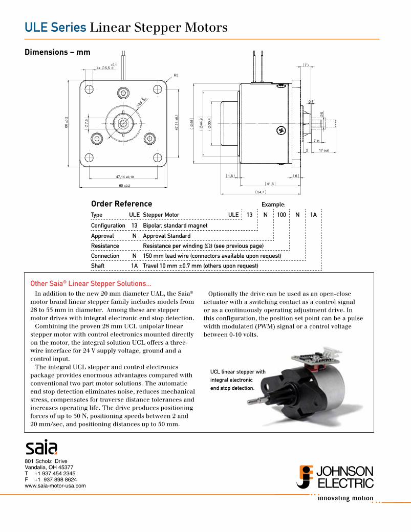
ULE Series LinearStepperMotors
Dimensions – mm
Other Saia® Linear Stepper Solutions...Inadditiontothenew20mmdiameterUAL,theSaia®
motorbrandlinearstepperfamilyincludesmodelsfrom28to55mmindiameter.Amongthesearesteppermotordriveswithintegralelectronicendstopdetection.
Combiningtheproven28mmUCLunipolarlinearsteppermotorwithcontrolelectronicsmounteddirectlyonthemotor,theintegralsolutionUCLoffersathree-wireinterfacefor24Vsupplyvoltage,groundandacontrolinput.
TheintegralUCLstepperandcontrolelectronicspackageprovidesenormousadvantagescomparedwithconventionaltwopartmotorsolutions.Theautomaticendstopdetectioneliminatesnoise,reducesmechanicalstress,compensatesfortraversedistancetolerancesandincreasesoperatinglife.Thedriveproducespositioningforcesofupto50N,positioningspeedsbetween2and20mm/sec,andpositioningdistancesupto50mm.
Optionallythedrivecanbeusedasanopen-closeactuatorwithaswitchingcontactasacontrolsignalorasacontinuouslyoperatingadjustmentdrive.Inthisconfiguration,thepositionsetpointcanbeapulsewidthmodulated(PWM)signaloracontrolvoltagebetween0-10volts.
UCL linear stepper with integral electronic end stop detection.
±0,260
-0,050
±0,10
7,5±0
,2
R5
60
25
47,14
4x 5,5 0+0,1
47,1
4±0
,1
2 17 out
7
in
5
6
0,5
7
1,6
54,7
41,6
55 30,4
44,9