steps for preparing files for 3d printingdclabs.wikispaces.asu.edu/file/view/steps for...
TRANSCRIPT

Digital Culture – Steps for preparing files for 3D printing – Carlo Sammarco- 10/31/11
-1-
Steps for preparing files for 3D Printing
1. Ensuring proper units
Go to Tools>Options and click on the Units tab. If the model units are not set to inches,
set them to inches and click OK.
A pop-up window appears asking whether you want to rescale dimensions to the new unit or
simply change the units. Click “No”. So if you were inadvertently working in millimeters before,
1 millimeter is now 1 inch.
2- Checking for size limitations
You are allowed up to 4 inches in any of the three axis (X,Y, or Z). To check the extents of your
model, go to Transform>Bounding box. Select all elements of your model and at the next

Digital Culture – Steps for preparing files for 3D printing – Carlo Sammarco- 10/31/11
-2-
prompt, accept the world as the coordinate system. The result will show an actual box around
your input in the display area and will display the extents of this bounding box in units in the
prompt…
The dimensions are listed in terms of X, Y and Z in that order. So in my example, if I can’t exceed
4 inches in any one dimension, I’m over by one inch in the X axis. To rescale, we can use the
bounding box to our advantage. Select all the objects (all your original objects plus the
bounding box) and go to Transform>Scale>Scale 3D. Make sure your end snaps are active. For
your “Origin point”, click on one of the corners in the X axis. For your “Scale factor or first
reference point”, click on the second corner in the X axis.
Initial geometry
Result after running the
Bounding Box command
2nd
click
1st
click

Digital Culture – Steps for preparing files for 3D printing – Carlo Sammarco- 10/31/11
-3-
Finally, for the “Second reference point”, enter the value you want to scale to (4 in this case).
When done you can delete the bounding box. If you re-run the bounding box command, you
can confirm that the change has taken place. Note that we are using a 3D scale, so the other
two axis will scale proportionately (i.e. the object will not distort)…
If your object exceeds the 4 inch limit in more than one axis, scale whichever is the largest axis.
3- Making sure everything is a closed solid
A 3D printer only prints solids. It doesn’t understand zero-thickness objects like individual
surfaces or joined surfaces that remain open along some edges. In the illustrations below, the
magenta colored edges indicate edges that are not joined…
After scaling
Individual surfaces A polysurface with two open edges A closed solid polysurface
Won’t print Won’t print Will print

Digital Culture – Steps for preparing files for 3D printing – Carlo Sammarco- 10/31/11
-4-
We have a few tools to make sure our objects are valid for 3D printing.
Type “what” in the command prompt. This will bring up information about whatever is
selected. In the example below, all the parts were booleaned together, forming one object. The
result is shown as a “closed solid”. Great!
In cases where there multiple objects are selected, these will be listed as separate entries in the
Object Description window (a separate ID: for each object). That means one entry for each
object. It can be tedious scrolling through to check each one. Since all we really need to confirm
is that everything in the design are solids, we can test using more visually direct methods.
At the prompt, type “SelOpenSrf”.
Anything that gets selected is an open, unjoined surface. This will not print. It will need to be
capped or joined to other surfaces so that it becomes part of a volume.
Digital Culture – Steps for preparing files for 3D printing – Carlo Sammarco- 10/31/11
-5-
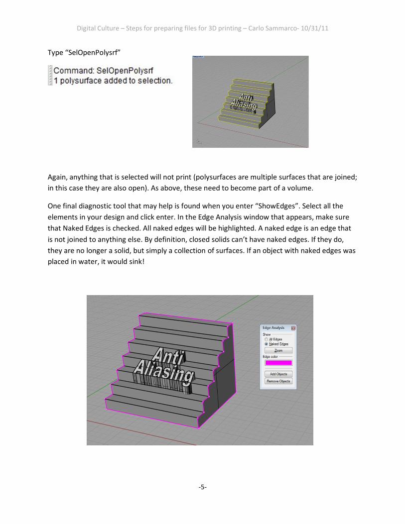
Type “SelOpenPolysrf”
Again, anything that is selected will not print (polysurfaces are multiple surfaces that are joined;
in this case they are also open). As above, these need to become part of a volume.
One final diagnostic tool that may help is found when you enter “ShowEdges”. Select all the
elements in your design and click enter. In the Edge Analysis window that appears, make sure
that Naked Edges is checked. All naked edges will be highlighted. A naked edge is an edge that
is not joined to anything else. By definition, closed solids can’t have naked edges. If they do,
they are no longer a solid, but simply a collection of surfaces. If an object with naked edges was
placed in water, it would sink!
Digital Culture – Steps for preparing files for 3D printing – Carlo Sammarco- 10/31/11
-6-
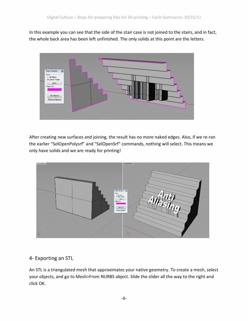
In this example you can see that the side of the stair case is not joined to the stairs, and in fact,
the whole back area has been left unfinished. The only solids at this point are the letters.
After creating new surfaces and joining, the result has no more naked edges. Also, if we re-ran
the earlier “SelOpenPolysrf” and “SelOpenSrf” commands, nothing will select. This means we
only have solids and we are ready for printing!
4- Exporting an STL
An STL is a triangulated mesh that approximates your native geometry. To create a mesh, select
your objects, and go to Mesh>From NURBS object. Slide the slider all the way to the right and
click OK.

Digital Culture – Steps for preparing files for 3D printing – Carlo Sammarco- 10/31/11
-7-
The mesh is created in the same location as the geometry.
To select it easily, type SelMesh in the prompt SelLast (to select the result of the last command)
and move the selection away from the original NURBS geometry.
NURBS
Mesh
Digital Culture – Steps for preparing files for 3D printing – Carlo Sammarco- 10/31/11
-8-
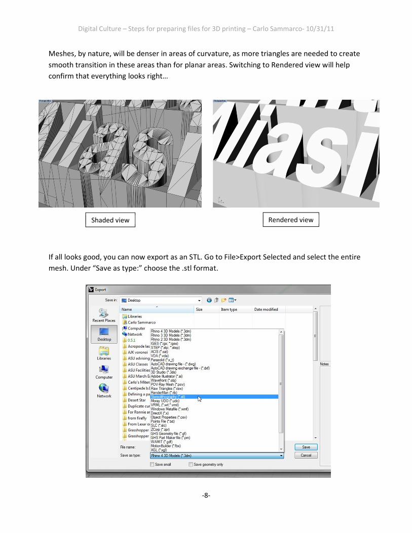
Meshes, by nature, will be denser in areas of curvature, as more triangles are needed to create
smooth transition in these areas than for planar areas. Switching to Rendered view will help
confirm that everything looks right…
If all looks good, you can now export as an STL. Go to File>Export Selected and select the entire
mesh. Under “Save as type:” choose the .stl format.
Shaded view Rendered view

Digital Culture – Steps for preparing files for 3D printing – Carlo Sammarco- 10/31/11
-9-
When you click “Save”, you will have one final window. Choose Binary.
You are DONE!