steve upson, horticulturist, the noble foundation · pdf filesteve upson, horticulturist, the...
TRANSCRIPT

Construction and Advanced Cultural Technology for Home, Community and Market Gardens
Steve Upson, horticulturist, The Noble Foundation
"But he who is noble devises noble things, and by noble things he stands."
– Isaiah 32:8
"Family" is the word that comes to mind when I describe both the people assisting with this publication and the environment in which it was developed.
I'm deeply grateful to all my Noble Foundation "brothers and sisters" who have made this publication possible. I want to give special thanks to Tommy Smith, Felix Peña, Steve Howe, David Miller and Dusty Pittman. Without their contributions, there would be no Noble Foundation Horticulture Center. Also, special thanks goes to the NF Publications and Visual Media Department and fellow Agricultural Division staff for editorial work, design and printing.
Most of all, I thank the patriarch of our "family," Lloyd Noble, founder of The Samuel Roberts Noble Foundation and visionary extraordinaire, without whom this work would not have been possible.
– Steve Upson, Horticulturist
An Old Chinese Proverb: If you wish to be happy for a few hours, drink wine until your head spins pleasantly; If you wish to be happy for a few days, get married and hide away; If you wish to be happy for a week, roast a pig and have a feast; If you wish to be happy all your life, become a gardener.
© 1997-2007 by The Samuel Roberts Noble Foundation, Inc.

Raised bed gardens built of boards at the Noble Foundation Horticulture Center, Ardmore, Okla.
The Noble Foundation Horticulture Center was created to assist the market gardener and the serious home gardener in producing high quality vegetables, fruit and flowers on marginal soils.
To accomplish this, a project was initiated in 1990 to research and demonstrate the advantages of raised bed gardening.
After 16 years of utilizing this growing system, I'm converted to the gospel of raised bed gardening, and I'm not alone.Raised bed gardening has become the gardening system of choice by thousands of serious gardeners. In recent times, U.S. gardeners havediscovered the benefits of growing with raised beds – benefits known to the Chinese thousands of
years ago. Some of those benefits include:
Improved drainage. This is the chief reason raised beds at the Noble Foundation are utilized. The soil at the horticulture center has poor internal drainage due to high clay content, making it inaccessible following periods of heavy rain.
Poorly drained soils tend to be oxygen deficient. Consequently, growth and development is impeded, and production potential is seldom achieved. Raising the soil above ground level allows excess moisture to drain out. As gravitational water moves out, air (oxygen) moves in. Plant roots require oxygen to function. This is why waterlogged plants fail to grow and even die if the poor drainage situation persists.
Higher yields. Because plants are uniformly spaced over the surface of a wide bed as opposed to single rows separated by pathways, a high plant density can be realized. This translates into increased yield per square foot of garden space.
Extended season. Raised beds heat up earlier in the spring. Because of their height, they intercept more of the sun's rays in late winter and early spring. This phenomenon permits earlier seeding and transplanting. Plants also grow faster once they are established.
No soil compaction. Once constructed, beds are never walked on during the growing season. In a traditional garden, walking along rows compacts the soil, often in close proximity to the plants. Plant roots struggle to penetrate compacted soil. Water and oxygen move more slowly in compacted soil. Surface tillage cannot alleviate compaction at a lower depth.

Temporary raised beds made with a tractor and a bed shaper.
Two basic types of raised beds are used today. One uses some type of border to maintain the shape of the bed. These are referred to as permanent beds. The other is borderless and, although less expensive to build, by its very nature is temporary.
Temporary beds are usually formed with a tiller or tractor-powered bed shaper. Much of the commercial vegetable production around the world is achieved on temporary beds. This production tends to be located on Class 1 soils — typically well-drained, loamy soils. These qualities enable them to be worked over a wider range of soil moisture conditions. Therefore, as
a rule, permanent raised beds can't be justified on these types of soils. Permanent beds are ideal, however, on sloped ground or on soils that possess a high clay content and drain poorly. Permanent beds effectively overcome the drainage limitations of tight clay soils. Erosion can be controlled on hillsides with the use of terraces and permanent beds.
The Bootstrap Community Garden, built of 1-inch by 6-inch lumber, in Ardmore, Okla.
Permanent beds utilize borders to contain the growing medium. Without borders, temporary beds are susceptible to erosion from rainfall and need continuous reforming. Unlike temporary beds dependent on fair weather for bed formation, permanent beds are always ready for service, even during periods of heavy rainfall. Seeding, transplanting and harvesting schedules can be maintained to a greater degree during adverse weather.
Some additional advantages of permanent beds involve bed height and versatility. Many individuals are not able to work in a typical raised bed garden due to physical limitations. Permanent beds can be adjusted to chair height or even waist height to accommodate gardeners with special needs.

Even hard-to-reach crops like strawberries can be harvested while comfortably seated on the bed border.
Accessories like trellises can make raised bed gardens even more productive.
Many permanent beds are constructed using rigid materials. Because of this, they can be engineered to readily accept plastic crop covers and mulches, trellises, harvest aids, bird netting, shade screens, wind breaks and other cultural and environmental control items.
At the Noble Foundation Horticulture Center, various raised bed materials and production methods have been evaluated over the past 16 years. Each type of material evaluated has advantages and disadvantages.
Three of the more promising unconventional materials evaluated include rubber lumber fabricated from used automobile tires, corrugated sheet metal and high density plastic mesh, commonly used for windbreaks and construction site barriers.
We will focus on the use of these three novel materials in raised bed construction. Information on preparing these beds for planting is also included.

Some of the different types of material that can be used for raised bed construction include: top to bottom, sand bags; straw bales, and c-purlin.
Also included is detailed information on topics such as plant spacing, crop support structures, fertilizer and water management, and season-extending technology developed specifically for the kinds of beds outlined here.
This publication is not intended to be a general gardening guide. Indeed, there are hundreds of those references available at local libraries and bookstores. Several excellent raised bed gardening references also are listed in the appendix.
Varieties and pest control recommendations are not included in this publication. Because of the variable nature of these topics, it is suggested the reader contact their local Cooperative Extension office for the most up-to-date information.
Gardeners don't have to be professional builders to construct and outfit the beds described in this manual. Most of the work can be accomplished with hand tools. A few power tools and specialized equipment are required in some situations. If these tools aren't available in the garage or work shed, don't panic. All of them are available through equipment rental stores.
Enough talk – let's get started!

Broccoli can be a prime raised bed crop, here growing in 20-inch-wide raised beds.
Over the past several years at the Noble Foundation Horticulture Center, experiments have been conducted with various bed widths. Crops were successfully grown in 6-foot-, 5-foot-, 4-foot-, 3 1/2-foot-, 3-foot- and 20-inch-wide beds. Every width has advantages and disadvantages.
Each gardener should consider several factors before deciding on a bed width. Some of these include:
Value. As bed width increases, construction cost per square foot decreases. A 5-foot by 20-foot bed constructed of 2-inch by 12-inch lumber is comparable in cost to a 3-foot by 20-foot bed of similar construction (approximately $100, not including labor or soil medium costs). The material cost per square foot is considerably less for the 100-square-foot bed ($1 per square foot) compared to the 60-square-foot bed ($1.66 per square foot).
Utilization of space. Another advantage of wide beds is increased utilization of space. Generally speaking, the wider the beds, the fewer the pathways. Where space is limited, more bed space and fewer paths translate into more yield per square foot of overall garden area.
Climate control devices. Many plastic row covers and mulches are available for use on 40-inch or narrower beds. Also, the narrower the bed, the easier it is to apply these devices. With wide beds, some of these materials must be custom made.
Personal stature. Tall individuals can easily reach the center of a 5-foot bed. Most people find it more convenient to use narrower beds. On wide beds, it is often necessary to place one foot on the bed and the other on the path, in order to reach the center. Stepping on beds is not encouraged because it compacts the soil. However, this practice is easier on the gardener because it takes strain off the back. This may sound trivial, but to anyone with a bad back, placing a foot on the bed makes all the difference in the world. No detrimental effect on yield has been noted from occasionally stepping on beds, especially when a large growing area is utilized. Anyone not wanting to step on beds can place a 1-inch by 12-inch standing board across the bed top. This will reduce the possibility of soil compaction.

Showing why 6-foot beds are too wide for most people.
At the Noble Foundation, our bed width of choice is 40 inches. This width combines the attributes of both narrow and wide beds.
Theoretically, beds can be constructed to any length. At the Foundation, most beds are 30 feet in length. A bed 40 inches wide and 30 feet long provides approximately 100 square feet of usable space. Most consumer fertilizer and pesticide products give rates of application on a 1,000 square feet basis. Moving the decimal one place to the left gives a rate for a 100-square-foot bed. This is the beauty of growing in this size of a raised garden – it makes computations easy! For example, 10 pounds of 13-13-13 fertilizer per 1,000-square-feet, a common rate for most garden soils, translates to one pound for the 100-square-foot garden.
Bed height is determined by the gardener's personal needs, budget and the nature of the materials with which the beds will be constructed. Most vegetable crops extract the vast majority of water and nutrients from the top 12 inches of soil. Any raised bed constructed on asphalt, concrete or other surface denying root penetration should be constructed to a height of 12 inches.
Good results have been obtained at the Noble Foundation in 6-inch high beds constructed over poor soil. A 6-inch-increase in soil depth above the existing grade will greatly enhance drainage.
Six-foot plastic mulch fits 40-inch-wide beds like a glove.
It appears that beds constructed 18 inches and above in height require extra fortification, often involving the need for anchored support columns or posts. High beds constructed of such materials as corrugated sheet metal require support posts because they lack rigidity.
By contrast, railroad ties can be stacked several high without the need for support. Small box-type beds are able to stand alone without additional support. The 4-foot by 8-foot box bed made of interlocking landscape timbers is an example of a stand-alone bed. Plan on "beefing up" any raised bed that will double for a bench.

Extra high beds require fortification.
There is no hard and fast rule as to the width of paths between beds. Anyone planning to use wheeled equipment such as a wheel barrow, garden cart or lawn mower between beds should make sure the paths are wide enough to handle the equipment. All of the Noble Foundation's 40-inch by 30-foot beds are on 5-foot centers. Path width was sacrificed for production area. Although the 20-inch-wide paths do not permit access by
garden cart, they provide easy access by one person with a harvest bucket.
Ideally, beds should be built on a north-south orientation. This alignment minimizes shading of low-growing plants. If it is impossible to orient the beds north and south, don't worry. Excellent results have been obtained growing crops in east-west oriented beds as well. In this situation, keep the tallest growing plants on the north side of the garden and try to group similarly sized plants together.
Make a scale drawing of the raised bed garden on graph paper. Once a bed width is selected, adjust bed length on the sketch to fit the site in the most efficient manner.
Box-type beds are excellent for classroom use at Oak Hall Episcopal School, Ardmore, Okla.
The perfect combination – 40-inch by 30-foot recycled tire beds constructed on 5-foot centers.

Plastic mesh provides a perfect windbreak for raised bed gardens.
Scale drawing of the Martin Luther King Jr. Outreach Center's Bootstrap Community Garden in Ardmore, Okla.
Select a sunny location for your raised bed garden. Generally, the more hours of sunlight the garden receives, the better the crops will perform. Sites that do not receive at least half a day of full sun should not be considered. Trees compete with the garden for nutrients and water as well as sunlight. Select a site out from under the drip line of trees.
The ideal location also should provide wind protection. Springtime winds are notorious for snapping the tender stems of young plants. Summer winds increase water use by plants and, under severe conditions, dry out or desiccate foliage. A border of shrubs is effective in reducing wind speed, as are various types of fences. An artificial windbreak can be constructed of high-density polyethylene (HDPE) plastic mesh available at most farm supply and home improvement stores. This is the same type of material used as barrier fencing around construction sites. Reducing wind speed reduces plant stress, which pays dividends in the form of earlier and greater yields.
Locate the garden near a water source. Although raised bed gardening offers many advantages, beds tend to dry out more quickly because of their elevation. Consequently, irrigation is mandatory. Consult the chapter on drip irrigation for information on installing a drip irrigation system in the raised bed garden.
A few property owners are blessed with productive soil. However, most are not. If soil at the planned site is inadequate from a gardening perspective, don't despair. None of the soil used in the Noble Foundation raised beds is native to the site – it has been trucked in. A quality soil delivered to the site allows the gardener to overcome the limitations imposed by tight clay or rocky soil.

Weed control prior to preparing the site is important for gardeners.
Establish a uniform grade before constructing the garden beds.
Prior to bed construction, eliminate all weeds and turf from the site. In the southern United States, bermudagrass is the turf of choice for sunny areas. Unfortunately, bermudagrass, affectionately referred to in some circles as "devil's grass," is a gardener's worst nightmare.
A glyphosate-based herbicide will control hard-to-kill perennial weeds such as bermudagrass and johnsongrass, in addition to a wide spectrum of other common weeds. The use of glyphosate has one drawback – it can only be used during the growing season. Care should be taken to not apply this herbicide on desired vegetation. Refer to the product label for application directions.
If the growing season is missed, consider controlling bermudagrass by undercutting the sod and removing it from the garden site. Don't expect much control by merely peeling off the top layer of soil, though. The deeper the cut, the greater amount of control achieved. Most of the soil can be recovered by
shaking the sod to remove the rhizomes and stolons (runners). Depending on the size of the garden, however, this can be an overwhelming task. An easier way is to replace the removed sod with a good quality top soil. Purchase enough extra for the raised beds and have it all delivered at one time.
Once weeds are controlled, an appropriate grade for the location should be established. Begin by loosening the soil by tilling or discing. This will permit movement of soil from high areas to low ones in the leveling or grading process. On occasion, it will be necessary to add fill to establish a level bed site or a uniform grade. This also is a good time to remove unwanted matter from the site such as stones, weeds, glass, metal or any other material that would prove dangerous or detrimental.

A sloped site and permanent beds — a perfect match!
Water standing between the beds is an indication the site was developed improperly.
It is not imperative that all beds be level with each other. It is important, however, that each bed be level. For example, on a slope where the long axis of the beds run across or perpendicular to the direction of the slope, each bed is constructed on a slightly different elevation. While the beds are not level one with another, each bed should be level. This is an important consideration because soil moisture and, to a lesser extent, mineral nutrients (especially nitrogen) flow downhill. In a level bed, gravitational forces are distributed evenly across the bed.
In order for irrigation water to be applied evenly, as in the case of drip irrigation, and distributed uniformly in the soil profile, the bed must be level. The bottom line is this: if your beds are not level, expect non-uniform crop growth.
On a hillside, terraces should be constructed for the raised beds. Hillsides make better sites for permanent raised bed gardens in one respect – they seldom have drainage problems. Therefore, if the site is extremely sloped, don't worry. With a little extra planning and preparation, a negative situation can be turned into a positive one.
If large numbers of beds are planned in close proximity to each other, or if converting a hillside into a terraced garden is being considered, seek the help of someone with surveying skills. If slope is not taken into consideration during site development, there is a very real chance some of the beds will be left standing in water after a rainstorm.
On small sites where only a few beds will be constructed, a line level is adequate for determining slope and leveling the site for individual beds. For larger areas, a surveying instrument or leveling instrument is preferred. Don't underestimate the importance of leveling the site and providing for drainage away from the garden. A little time invested in site preparation will insure convenience and peak performance for years to come.

A fence makes a good line of reference.
The following procedure can be used to establish the boundaries and elevation of a large square orlrectangular raised bed plot.First, the site should have been adequately prepared and a grade established. Ideally, a surveying instrument was used to level the site or establish a uniform slope. If you have difficulty with this step, consult a soil conservationspecialist, civil engineer, home builder, vocational/technical instructor or anyone with surveying skills.
Figure 1. Establishing a square plot
To do a good job laying out your plot, you will need the following tools: sledge hammer, carpenter's square, level, hammer, several small and large nails, twine or heavy string, two rebar stakes, eightwood stakes, a surveying instrument, measuring rod, twomeasuring tapes long enough to reach across the plot and apermanent marker. Begin by marking off one side of the plot. It isusually desirable to make this side parallel or perpendicular to theside of a nearby building, road or fence line. However, if the line ofreference does not run true north-south or east-west, considerusing a compass to establish the first side.
Drive two rebar stakes (points A and B) an equal distance from the line of reference or locate them based on compass headings (Figure 1). Make sure the distance between points A and B is greater by several feet than the actual plot measurement. String a line between points A and B.
When using a tape measure, make sure the tape is taut. Use the same tapefor all measurements and be consistent in your technique. Although not required, the presence of a second person greatly simplifies and speeds up
the measuring process.
Initial squaring of plot can be accomplished with the aid of a framing square.
Next, push a large nail (a 16-penny or gutter nail is best) into the soil directly under the string and at the point you designate to be one corner of the plot (point C in Figure 1). Place another nail directly beneath the string at thepoint designating an adjacent corner of the plot (point D). Line CD represents one side of the plot. Measure the distance to both corners on the opposite side of the plot, designating their locations (points E and F) with nails. Use a framing squareto make corners C and D as close to a 90-degree angle as possible.

The 3-4-5 method of establishing a right angle; use a carpenter's level to insure the line is directly above the nail; and obtaining a diagonal measurement to be sure the plot is square.
Now make sure corner C (angle FCD) forms a 90-degree angle. This is best accomplished by using the 3-4-5 triangle ratio (referring to lengths of the sides of a right-angled triangle whether in inches, feet, meters, etc.). The beauty of this procedure is that it enables you to square up the entire plot using one corner set at 90 degrees. Refer to Table 1 to determine the best ratio to use for your plot.
In our example in Figure 1, the plot is of sufficient size to justify use of the 24-32-40 ratio. A 90-degree angle is established at corner C by first measuring 24 feet from point C and placing a nail directly under the string (point G).
Next, two measuring tapes are attached to the nails at points C and G. A nail is placed at the union (point H) where the 32-foot and 40-foot marks of the respective tapes converge.
After removing the measuring tapes, a line is strung between points C and F. To insure the string is straight, it should be taut, but not so taut as to move the nails. The string should be positioned directly above the nail at point H. If not, the nail at point F is adjusted accordingly. Corner C (angle FCD) should now be approximately 90 degrees.
The distance between points F and E should be the same as the distance between points C and D. If not, the nail at point E (not F) is adjusted accordingly. Corner D (angle EDC) should now approximate 90 degrees.
If you've followed these steps, your plot should be close to square. For the final proof, lines CE and DF must be of equal length. If the lengths are unequal, observe the following guidelines to square the plot:
1. Only adjust the location of points E and F. 2. Move the nails in only one direction along line EF, never towards or away from C or D. 3. When making an adjustment, always move nails in the same direction and at an equal distance.
For example, if line CE is found to be 4 inches longer than line DF, move both nails 2 inches to theleft along line EF. Measure lines CF, DE and EF to make sure they are still the proper lengths.Next, measure CE and DF again. Repeat procedure until plot is square.

Table 1 3-4-5 90° Angle ProcedureShortest dimension
Ratio (length or width) of plot3, 4, 5 Less than 20 feet6, 8, 10 Less than 40 feet
12, 16, 20 Less than 60 feet24, 32, 40 Less than 80 feet
Next, prepare eight 2-inch by 4-inch by 24-inch wood stakes. Drive a small nail into the broad (4-inch) side of each stake, four inches from the top. Locate the stakes 18 inches from each corner, centeringthem on each boundary line. Drive the stakes into the ground only a few inches at this time. Make sure thestakes are oriented with nails facing away from the plot.
Figure 2. Both A and D stakes should be driven to the same height above ground (not the same elevation), with the height determined by the height of the beds. Because the site is sloped, A and D will be at different elevations. To insure a uniform slope across the plot, use a leveling instrument to level A and B stakes with each other and C and D stakes with each other.
Select one stake and drive it to a height above the soil surface equivalent to the height of the bed. For example, if your choice is rubber lumber or plastic mesh, set the stake 8 inches and 6 inches above the soil surface respectively. If you want to construct corrugated sheet metal beds, set the stake 14 inches above soil surface.
Use a surveying instrument and leveling rod to establish the remaining stakes at the same elevation as the first. An alternative method, although less accurate, is to use string lines and line (bubble) levels to set the other seven stakes level with the first.
Some sites have too great a range in elevation to try to level. If this is the case with your site, refer to Figure 2 for details on preparing a plot on sloped ground.
Next, establish the exact position of each boundary (perimeter). Attach strings to the nails on each stake, making sure strings run over the top of the stakes. Be sure each string line is taut.
Use a carpenter's level or plumb bob to position each string line precisely above the nail points. Mark the position of each string line on the top of each stake with a marker or pencil. Mark both sides of the string. If a string breaks or you need to remove the strings prior to bed construction, they may be reattached to their exact location using the pencil marks.
Drive the first stake to a height equivalent to that of the bed; "fine tune" the position of boundary
lines with the use of a level; and designate the location of each boundary line on stakes with a waterproof marker.
Congratulations! You have now defined the exact perimeter, or boundary, and bed elevation of your raised bed plot.

Recycled auto tire beds — an idea whose time has come!
United States residents throw away enough tires each year to more than circle the globe. According to the Environmental Protection Agency, more than 290 million scrap tires are generated each year in the United States. To compound the problem, anywhere from 1.5 billion to 3 billion tires are already piled on roadsides and in dumps and vacant lots.
Most states no longer let landfills take whole tires because they can capture gas and squeeze up through other garbage to break through the heavy clay layer used to cap landfills.
Uses for recycled tires have become as varied as imagination allows. Strips of rubber are cut into shoe soles and fabricated into mats for erosion control. Crumbed rubber becomes part of hockey pucks, road pavement, racetracks for people and horses, playground cover and custom soil mixes.
Add to this list rubber lumber for raised bed gardens. After several years of trial and error, modification and evaluation under field conditions at the Noble Foundation's Horticulture Center, raised beds constructed of rubber boards fabricated from used tire treads have proven successful in producing a variety of vegetable and floral crops.
While material cost is minimal, a fair amount of time and labor is required to fabricate rubber lumber. If hired labor is used for this task, the cost advantage of using rubber lumber in bed construction is lost.
Now, for the good news! Cost of material to construct a recycled auto tire bed, excluding soil mix, runs as low as 20 cents/square foot of bed, less than half the cost of a 1-inch by 6-inch treated lumber bed.
If you're looking for a raised bed design that will provide countless years of service, is low maintenance, safe, environmentally friendly, has a low material construction cost and is easy on equipment, this bed is for you!

Avoid odd-sized tires such as low profile tires and 16-inch truck tires.
The ideal type of tire used to fabricate rubber boards is a well-worn, 15-inch steel belted passenger tire. The lack of tread makes the tire more flexible and easier to work with, and 15-inch tires are a common size for passenger vehicles.
When a screw is inserted into a tire tread reinforced with steel belts, the strands of wire wrap around the screw, ensuring a secure fastening. Fortunately, the vast majority of tires manufactured today are steel
reinforced. Sixteen-inch tires should be avoided, as they are less flexible due to their heavier build. Also avoid self-sealing tires, as the sealing compound is not compatible with gardening. And avoid low profile tires, as they tend to be stiff and inflexible.
A simple elevated workbench for extra long rubber boards.
Several types of power tools are required to fabricate rubber boards. A power drill equipped with a Phillips head bit will speed up the fastening process. A grinder does quick work removing any screw tips protruding from the sides of rubber boards. A chop/cut-off saw works best to prepare large numbers of rebar sections.
A jigsaw serves to slice and dice the tires. Steel reinforced tire tread is easily cut using a jigsaw equipped with a metal cutting or hacksaw blade. For easier cutting, choose a saw with a high reciprocating speed. Purchase only fine-toothed blades for smooth cutting. We have good results using blades with 18 teeth per inch (TPI).
Use a workbench when fabricating large numbers of boards. For extra long boards, use 2-inch by 12-inch lumber supported by saw horses or concrete blocks as a working surface. Protruding screw tips can damage your workbench surface, so it's a good idea to cover the surface with a piece of particleboard.

Using a jigsaw to cut through tire tread.
Hardware requiredItem Quantity
7/8-inch, No. 10 Phillips head sheet metal screws
Two per foot of board
Tools requiredJigsaw equipped with hacksaw bladesHand drill equipped with Phillips bitHand grinderEye protectionTape measureVinyl knife (for initiating cut in sidewalls)Tires required: approximately 6 tires/30-foot board
Rubber boards can theoretically be fabricated to any length. At the Noble Foundation, we've fabricated boards up to 30 feet long. Boards longer than 30 feet are not recommended because of their excessive bulk and weight.
To produce a rubber board, select a group of tires having similar tread width. Start by cutting a small slit in the sidewall close to the tread large enough to insert a jigsaw blade. Make one cut through the tread of each tire using the jigsaw equipped with a hacksaw blade.
Next, remove the sidewalls using the jigsaw. Cut as close to the tread as possible but avoid cutting into the steel bolts located in the tread. This produces sections of tread 5 to 7 feet in length and 6 to 8 inches in width, depending on tire size.
Based on the length of board needed, arrange the appropriate number of tread sections on your work bench end-to-end, making sure tread is facing down. Working from one end, slide the second section under the first section 6 inches and secure with four sheet metal screws. To insure a strong union, place a screw in all four corners of the overlapped sections of tread, being careful to not get too close (within one inch) to the edge.

Use a jigsaw to remove sidewalls from the tires.
Fastening one piece of tread to another. Orient pieces with tread facing down.
Forming the loop at the end of the board.
Place the third section of tread under the second and overlap 6 inches. Secure this second union in a manner like the first.
Slide the fourth section of tire under the third and fasten. Repeat this procedure until the desired length of board is obtained. Adjust the length of the last section by cutting or simply overlapping the excess with the previous section.
Form a tight loop at both ends and secure with a minimum of two sheet metal screws. The loops need to be of sufficient size to accept a 5/8-inch diameter piece of rebar.
Using a jigsaw equipped with a hacksaw blade, cut 6-inch-wide pieces of rubber from sections of tread. The use of a tread-cutting jig makes this task easier.
Place these pieces of rubber on the board, tread facing up. Space the pieces on 18-inch centers and secure each piece with two screws, one placed an inch from the left edge and the other an inch from the right, equidistant top to bottom.
Rebar stakes inserted through these "pockets" allow the board to stand erect and be anchored to the ground. Overlapping sections of tread also serve as pockets. Take this into consideration when spacing the small pieces of rubber on the board.
When the board is finished, flip it over and remove the screw points, using a grinder. Repeat procedure for each additional board required.

Sectioning tread with a cutting jig made from three laminated 2- by 12-inch boards. A gap between the top two boards is necessary to provide clearance for the blade.
Fastening a 6-inch wide piece of rubber to the board to form a pocket.
A 30-foot rubber board ready for transport.
Removing screw tips with a grinder.
Use a grinder to remove wire stubs

A 30-foot rubber board rests in rebar "cradles".
Hardware requiredItem Quantity
3/8-inch by 18-inch* rebar stakes
One for every 18 inches of border
5/8-inch by 36-inch* rebar stakes
Four per bed
5/8-inch by 10-inch rebar rod (for use with sling)*May vary, depending on soil type
Tools requiredPower hacksaw or chop saw for preparing stakesSledge hammerHand winchWire slingString lineShovelGarden rakeCarpenter's levelSafety glassesTape measure
Using the appropiate perimeter stake line, mark off the corners of one end of each bed by driving 5/8-inch by 36-inch-length rebar stakes into the ground next to the string. This means that, using our example of 40-inch beds on 5-foot centers, the stakes would be positioned at 0, 40, 60, 100, 120, 160, 180 and 220 inches and so on the length of the string, depending on the number of beds to be constructed.
If the plot is level, stakes may be driven flush with the string, 8 inches above grade. If the plot is sloped perpendicular to the long axis of the beds, only the first corner stake of each bed (0, 60, 120, etc.) should be driven flush with the line and a carpenter's level used to level the second corner stake with the first. Orienting the stakes at a slight angle leaning away from the bed will help minimize their movement when the rubber boards are stretched.
Use the same procedure to mark off the corners on the other end of the beds, with one exception: drive the stakes into the ground only a few inches, as they will need to be pulled out and repositioned at a later time.
Working across the plot, designate the exact location of the first bed border (rubber board) by stringing a line between the first set of rebar end stakes. Every 3 feet along the string, drive a pair of 3/8-inch rebar stakes 1/2-inch to either side of the string. Drive the stakes into the ground only a few inches, as they will need to be relocated later. These temporary stake "cradles" act to hold theboard erectly on edge.

Use of a chop saw to make rebar stakes

Use a string line to make certain the board is level.
Remove the string lines from the rebar end stakes and the perimeter stake lines as they will be in the way when installing the bed border. Pull up the temporary end stake and lay it aside.
Move a board into place alongside the row of stake cradles. Loop one end of the board over the permanent 5/8-inch stake. Place a portion of the board in each cradle until the entire board is on edge.
Attach the other end to a hand winch by means of a 10-inch piece of 5/8-inch rebar and the wire sling. Anchor the winch to a stationary object such as another stake. Make sure the board is oriented correctly. Pockets should be facing outward (towards the path) and the tread facing inward.
Remove excess slack by stretching the board. Applying too much tension may result in personal injury! With the board under tension, remove the cradle stakes one at a time and insert into the pockets. Drive the stakes to within 3 inches of the top of the board and stop.
Use a hand winch to stretch 30-foot-long rubber boards prior to staking.

A 40-inch by 30-foot rubber board bed ready to fill with soil mix
The last stake to be driven is the remaining 5/8-inch stake. First, release tension on the winch and remove the sling and rod. Place the stake through the loop and drive it into position.
Replace the perimeter stake lines. String a line across the perimeter stake lines parallel with the bed border. Finish driving the 3/8-inch stakes to their final depth. Use the string line to gauge proper elevation of each stake. The border can be considered level when the top edge is flush with the stakes. Occasionally, because of high spots, soil may need to be removed under a border before it can be leveled.
You have now completed a rubber board border. Repeat the procedure to install additional borders. When borders have all been constructed, fabricate end pieces from single sections of tread. It is now time to fill the beds. One of the drawbacks associated with permanent raised bed gardening is the significant amount of time required for bed construction. Because time is money, this is of particular concern to the market gardener. In response to this problem, we began searching in 1991 for a relatively inexpensive material that could be quickly and easily used to construct raised beds. To date, experience has shown that a material known as HDPE (high-density polyethylene) plastic mesh is such a material.
An end piece made from a single piece of tire tread

Tomato production in raised beds made of mesh.
The particular type of mesh we've evaluated at the Noble Foundation is commonly usedfor windbreaks and barrier fences. The meshdesign enables the material to be anchored tothe ground using rebar stakes woven throughthe fabric. Unlike rubber lumber, whichrequires fabrication, the only tool required toprepare the mesh is a pair of scissors.
There are several brands of plastic fencing onthe market. A list of companies handling these materials appears in the Appendix. Also check your local home improvement center foravailability of these products.
The majority of fencing products when used as a bed border will not retain soil, requiring the use of a liner. At the Noble Foundation, we've had good luck using strips of roll roofing as liners in our plastic mesh beds. Roll roofing is available at most lumberyards and home improvement centers.
Be careful not to select a fencing material with too tight a mesh. It can be difficult, if not impossible, to weave the 3/8-inch rebar anchor stakes through the mesh if the mesh weave is too tight.
Obviously, a plastic mesh border will not stand up to the level of abuse of more rigid, heavier materials such as treated lumber and rubber lumber. Knowing this, several precautions should be taken. When using power equipment such as a weed trimmer or a rototiller in or around beds, take care to not come in contact with the mesh borders. For this reason, we do not turn a walk-behind tiller around in the bed, but wait until the tiller is exited out of the bed before turning it around for the next pass. When tilling close to the border, maintain a distance of 4 to 6 inches between the tiller and the border at all times. This rule also applies to the smaller, hand-held mini tillers. Despite these drawbacks, a properly maintained bed constructed of plastic mesh will provide several years of useful service.
If you're looking for a quickly and easily constructed raised bed garden at about half the initial material cost of a 1-inch by 6-inch treated lumber bed, consider HDPE plastic mesh.

Cutting mesh borders couldn't be easier – household scissors are sufficient to get the job done!
Hardware requirednone
Tools requiredScissors
Tape measureMaterial required
One 5-foot by 100-foot roll of mesh material makes approximately 1,000 feet of border 6 inches wide. This is enough material to construct 16 beds, 30 feet in length.3/8-inch by 8-inch rebar rod, two per border (four per bed)Roll roofing cut into 6-inch wide strips
Prepare borders by cutting material into strips 6 inches wide and 6 inches longer than the length of the bed you are constructing. Scissors work fine for this cutting.
Form loops on both ends of the mesh strips by bending material back on itself approximately 4 inches and securing with the 8-inch pieces of 3/8-inch rod woven through both layers of material.
If prepared properly, each mesh strip will be several inches shorter than the bed length. The mesh will stretch when tension is applied using a hand winch.
A crop of cut flowers growing in plastic mesh beds

Roll roofing makes an effective liner for plastic mesh beds.
Hardware requiredItem Quantity
3/8-inch by 18-inch* rebar One for every 18 inches of border
5/8-inch by 30-inch* rebar Four per bed *May vary, depending on soil type
Tools required Chop saw for preparing stakes Sledge hammer Hand winch Wire sling Shovel Garden rake Carpenter's level Tape measure Safety glasses
Using the appropriate perimeter stake line, mark off the corners of one end of each bed by driving 5/8-inch rebar stakes into the ground next to the string. Using our example of 40-inch beds on 5-foot centers, the stakes should be positioned at zero, 40, 60, 100, 120, 160, 180, 220 inches and so on along the length of the string, depending on the number of beds to be constructed.
If the plot is level, stakes may be driven flush with the string, 6 inches above grade. If the plot is sloped perpendicular to the long axis of the beds, only the first corner stake of each bed (0, 60, 120, etc.) should be driven flush with the line and a carpenter's level used to level the second corner stake with the first. Orienting the stakes at a slight angle leaning away from the bed will help minimize their movement when the rubber boards are stretched.
Mark off the corners on the other end of the beds using the same procedure described previously, with one exception: don't drive stakes to their final elevation. Rather, drive them into the ground only a few inches, as they will need to be pulled up and attached to the material prior to their permanent placement. Remove the perimeter stake lines as they will be in the way when installing the plastic strips.
Next, attach one end of the plastic strips to the permanent 5/8-inch stakes by looping the material over the stakes.

Use a hand winch to stretch the mesh before driving the stakes into place.
Pull one of the strips of material across the plot and attach the free end to a hand winch by means of the8-inch piece of 3/8-inch rebar and a wire sling. Applying tension to the material using the winch will ensure a nice, tight, straight border. With tension applied, make sure the strip of material rests against the temporary 5/8-inch rebar stake.
If this is done properly, the material should be standing on edge. While under tension, remove the temporary 5/8-inch endstake, place through the loop and drive into the ground. Anchor the material to the ground using 3/8-inch stakes positioned every 18 inches. Be sure to weave the rodthrough the material prior to driving them into the ground.
Drive the stakes to within 3 inches of the top of the material (9 inches above ground level) and stop. Care should be taken not to stretch the material too tight, as it could rip when the support stakes are woven through the mesh.
Replace the perimeter stake lines. String a line across the perimeter stake lines parallel with the strip of material. Finish driving 3/8-inch stakes to their final positions. Use the string as a gauge to ensure all the stakes are set at the proper elevation.
Secure the mesh to the ground with 3/8-inch rebar stakes.
You have now completed a plastic mesh border. Remove the winch and repeat the procedure for other borders.
Next, line the inside surface of each border with strips of the roll roofing material. To hold the liner in place prior to filling the bed, place a shovel scoop of soil against the liner every couple of feet.
Finish construction by placing end pieces on the beds. You can fabricate end pieces out of the mesh fencing, treated lumber or, better yet, pieces of tire tread (see section on recycled auto tire bed assembly). You are now ready to fill the beds!

Table 1. Building materials needed to construct one 40-inch wide x 30-foot-long corrugated sheet metal raised bed
Quantity Item Description Unit Price Total210 foot 5/8-inch sucker rod $0.28 $58.80
2 2-inch x 4-inch x 12-foot treated lumber $5.97 $11.944 2-inch x 4-inch x 10-foot treated lumber $5.39 $21.561 2-inch x 4-inch x 8-foot treated lumber $4.97 $4.973 26 -inch x 12-foot corrugated sheeting $10.60 $31.801 10-foot steel angle (flashing) $5.85 $5.85
67 foot 1-inch x 2-inch treated lath $0.19 $12.734 2-inch x 4-inch saddle connector $1.17 $4.68
1 pound 1-inch metal-to-wood screws $4.00 $4.001 1/4 pound 1 1/2-inch joist hanger nails $2.64 $2.64
1 pound 1 5/8-inch exterior wood screws $6.07 $6.071 pound 3-inch exterior wood screws $6.07 $6.07
Total $171.11
One limitation of the recycled auto tire bed design is that, at 8 inches high, it is too low to work while in a seated position. Consequently, recent efforts have focused on the development of a relatively inexpensive high profile raised bed.
Corrugated sheet metal beds ready for planting
After evaluating several materials and construction techniques, we settled on a corrugated sheet metal-lined bed supported by a frame made of sucker rod and 2-inch by 4-inch treated lumber.
Of all the different high profile bed designs we've evaluated, the corrugated sheet metal design is the quickest and easist to construct.
The material cost to construct a corrugated sheet metal bed, excluding soil mix, is approximately $1.70 per sq. ft.
Refer to Table 1 for a list of building materials to construct one 40-inch by 30-foot corrugated sheet metal bed.
Refer to Table 2 for a list of components required to assemble one 40-inch by 30-foot corrugated sheet metal raised bed.

Table 2. Components required to assemble one 40-inch by 30-foot corrugated sheet metal raised bed
Quantity Component70 5/8-inch x 36-inch sucker rod2 2-inch x 4-inch x 10-foot 6-inches treated lumber2 2-inch x 4-inch x 10-foot treated lumber2 2-inch x 4-inch x 9-foot 6-inches treated lumber2 2-inch x 4-inch x 3-foot 1-inch treated lumber4 13-inch x 12-foot corrugated sheeting2 13-inch x 9-foot corrugated sheeting2 13-inch x 3-foot corrugated sheeting4 12-inch steel flashing
(Cut to Fit) 1-inch x 2-inch treated lath

Hardware
1-inch self piercing metal-to-wood screws
1 1/2-inch joist hanger nails (9 gauge)
1 5/8-inch exterior wood screws
3-inch exterior wood screws
Tools Required Carpenter's square, drill press or hand drill, chop saw or cutting torch, circular saw, tin snips, power grinder, 11/16-inch wood drill bit, eye and ear protection
Figure 1.
Begin by preparing the wood component of the frame. Cut to size the following 2-inch by 4-inch lumber: two 10 1/2-foot-long boards; two 10-foot-long boards; two 9 1/2-foot-long boards; two 37-inch-long boards.
Using the schematic in Figure 1, mark the location for the stake holes on the narrow side of each board. Be sure to center the mark on the board. Use an 11/16-inch bit to drill the holes. Be sure to keep the bit vertical in order to accurately drill through the center of the board. For speed and accuracy, consider using a drill press for this job.

Mark locations for holes, being sure to center each hole for maximum strength.
Hand drill
Drill press
Next, prepare the stakes. Use a cutting torch or chop saw to prepare 70 5/8-inch by 36-inch long sucker rod stakes. If you're building more than one bed, consider using a cutting torch to make the job quicker. Use a grinder to remove the burrs from the ends of the stakes. A stand-mounted grinding wheel works best for this task. (Note: If sucker rod is not available, rebar can be used as a substitute. An 11/16-inch hole will not readily accept a 5/8-inch diameter rebar so you will need to use a ¾-inch bit. Because drilling larger diameter holes further compromises the strength of the lumber, it is imperative that the holes be drilled accurately).
Cutting torch
Chop saw
Use tin snips to prepare four 12-inch-long pieces of angled metal flashing. The flashing is used to seal the bed corners.
To prepare the bed liner, cut the corrugated sheet metal in half lengthwise using a circular saw. Do not attempt to cut the sheet metal without reversing the blades. Hot fillings are ejected as the metal is being cut, so be sure to wear safety glasses. Cutting the metal is also very noisy, so be sure to wear earplugs.
Complete the fabrication of the liner by cutting a 3-foot-long section off of two of the sheets. When finished, you should have four 13-inch by 12-foot sheets, two 13-inch by 9-foot sheets and two 13-inch by 3-foot sheets.
Use tin snips to prepare flashing.
Use of circular saw to cut sheet metal

Bed Assembly Using a permanent marker, designate the corners of one end of each bed by marking the appropriate perimeter stake line. Using the example of 40-inch beds on 5-foot centers, mark the string at zero, 40, 60, 100, 120, 160, 180, 220 inches and so on along the length of the string, depending on the number of beds to be constructed. Mark off the corners on the other end of the bed using the same procedure.
Next, install the bed border stakes. Place one edge of a carpenter's square against the outside edge (away from the plot) of the perimeter line, making sure the apex is on the first ink mark (refer to picture below). Position a 5/8-inch by 36-inch-long sucker rod stake at the end of the adjacent arm of the square on the corner that is in line with the ink mark. Drive the stake into the ground to a depth of 18 inches. Repeat the process until all of the stakes on both ends of the beds are in place.
Because the perimeter stake lines are under tension, they will have a tendency to stretch causing them to sag over time changing the location of the ink marks. To ensure accuracy, don't delay installing the stakes. If you can't finish the job in one day, disconnect the lines and reconnect them when you start again, making sure the previously installed stakes match their corresponding ink marks.
Designate the exact location of the first border by stringing a line between the border stakes at each end of the bed. Adjust the elevation of the line so it just touches the perimeter lines. If the line does not line up with the ink marks on the perimeter line, make needed adjustments to the stakes. Repeat this process when locating each additional border.

Starting at one end of the bed (perimeter line), measure along the border string line and make a mark at 10 1/2-feet and another at 20 1/2-feet using a permanent marker. These marks designate the location of the 2-inch by 4-inch board unions that form the bed frame.
Set concrete blocks directly under the marks on the string and at both ends 6 inches inside the perimeter lines.
Next, position the drilled 2-inch by 4-inch boards on the concrete blocks. The ends of the boards should join over the blocks. The 10 1/2 and the 9 1/2-foot-long boards should be oriented such that the ends with holes drilled 3 inches from the end are next to the perimeter lines. The 10-foot-long board should be in the middle.
Connect the boards using 2-inch by 4-inch saddles and joint hanger nails.
With the 2-inch by 4-inch frame section turned on edge, use wood shims to raise the elevation of the frame. Adjust the elevation so the top of the frame is even with the string line. Because the string line represents the outside surface of the bed, be sure to position the outer surface of the frame inside the string (towards the bed interior).

Next, drop a 5/8-inch by 36-inch sucker rod stake into each hole, and with the help of a sledgehammer, drive the stakes flush with the top of the boards.
To lock the frame in place, use 1 5/8-inch wood screws to fasten 1-inch by 2-inch wood lath to the top of the wood frame. Space the screws one foot apart.
You can now remove the string line and the concrete blocks and shims from beneath the frame section.
Move to the other side of the bed and repeat process. Remember to place the 2-inch by 4-inch boards in the same sequence and orientation as the previous group and locate them on the inside of the line towards the bed interior.
Once you've completed construction of the side frame sections, install the sheet metal lining.
Start by using a chalk line to mark a line on the inner surfaces of both frame sections 1 3/4-inches below the top of the frame. Use a carpenter's square to mark a vertical line on the inner surface of both frame sections 1 1/2-inches from each end.
You will need two 12-foot long pieces and one 9-foot piece of sheet metal for each side. It doesn't matter in what sequence you install the pieces. The pieces are purposely oversized so they will overlap each other. Plan on overlapping the pieces about 20 inches. Align the top of the sheets with the chalk mark and remember to recess the inches recess the sheet metal 1 1/2-inches from each end of the side framesections. Be sure to orient the sheets with the top edge sloping towards the frame. This will eliminate any gap between the metal and the frame, making it more difficult to cut your hands on the metal liner when working in the beds.
Attach metal liner making sure the top edge is sloped towards the frame.

Attach metal liner making sure the top edge is sloped towards the frame.
recess the sheet metal 1 1/2-inches from each end of the side frame sections. Be sure to orient the sheets with the top edge sloping towards the frame. This will eliminate any gap between the metal and the frame, making it more difficult to cut your hands on the metal liner when working in the beds.
Attach the sheet metal to the frame using 1-inch self-piercing metal-to-wood screws. Space the screws 1 foot apart and 3/4 inches from the top edge of the metal.

Before constructing the bed ends, install a piece of angled flashing at all four corners. Insert one arm of the flashing between the frame and the liner, making sure the center fold of the flashing rests against the end of the liner. The bottom edge of the flashing should align with the bottom edge of the liner.
Secure the flashing to the liner using metal-to-wood screws (or sheet metal screws). To prevent injury, be sure to remove protruding screw tips.
Complete the frame by installing the end sections. Attach a 2-inch by 4-inch by 37-inch-long drilled board to each bed end using 3-inch wood screws. Before fastening, make sure the upper and outer surfaces of the boards are flush with the upper and end surfaces of the 2-inch by 4-inch boards in each side frame section.
Drop 5/8-inch by 36-inch-long sucker rod stakes into each hole and drive the stakes flush with the top of the boards.
Lock the end frame sections in place using pieces of lath and wood screws.
Finish construction by installing a 3-foot-long piece of sheet metal to the inside surface of each end frame section. Be sure the top of each piece is level with the top of the metal sheets on the sides of the bed before fastening with metal-to-wood screws.
Last but not least, secure the metal liner at each end of the bed to the flashing on each corner using metal-to-wood screws. Don't forget to clip off the protruding screw tips.
You have now completed a corrugated sheet metal bed. Construct additional beds using the previously described procedures.
It is now time to fill the beds.

Layer soil components and mix a few inches at a time.
If at all possible, use existing soil as the primary source to fill the beds. If your garden site is elevated and blessed with good quality soil, consider scraping off an appropriate amount of topsoil during site preparation and setting it aside. This procedure is recommended only for sites located on high ground. The depression created will be prone to flooding unless water can be channeled off the site.
The same scenario occurs when soil located in pathways between the beds is removed and used to fill the beds. A heavy rain will fill the lowered pathways, turning them into quagmires. Unless the water can be channeled away from the plot to a lower area, the problem will remain.
The ideal soil for your beds is a loam. Loam soils contain varying amounts of sand, silt and clay. Most gardeners prefer a sandy loam because of its favorable drainage characteristics and ease of tilth.
By design, raised beds are endowed with superior drainage characteristics. Consequently, they can utilize a broad spectrum of soil types and be effective. Clay loam soils, which are often unacceptable, can work quite nicely in raised beds if amended with sand and organic matter.
In situations where existing soil quality, quantity or site topography is inadequate, an alternative source of fill will be needed. Ask to examine any sample of fill you are considering purchasing. Spend a few dollars to have the soil tested for salt content and texture in addition to nutrient content.
For best results, consider amending the fill soil with additional materials. At the Noble Foundation Horticulture Center, good results have been obtained by using a mix consisting of equal parts (volume) of either fine sandy loam or silt loam and peat moss. Fine-textured soils such as clay loams can be amended with equal parts sand and peat moss. Avoid using sand exclusively or in combination with only peat moss. Sand, even with copious amounts of added organic matter, tends to excessively drain, making it prone to nutrient leaching.
If you are working with large numbers of beds or deep beds, the amount of peat moss recommended might be cost prohibitive. Don't worry. Simply use the amount you can justify. With continued applications of peat moss or other sources of organic matter such as compost, the tilthand water and nutrient holding capacity of the soil will be improved over time.

A soil portioning tool, when used with a front-end loader, directs soil into the beds, saving time and energy during bed filling.
Calculate the amount of fill required by determining the total volume of your beds. Multiplying width times depth times length will give volume. As an example, the volume of a bed 3 1/3-foot wide (40 inches) times 1/2-foot deep (6 inches) times 30-feet long is equal to 50 cubic feet or approximately 2 cubic yards (27 cubic feet/cubic yard). If you constructed 10 of these beds, you would need to order 20 yards of soil or a combination of soil and sand. Do not consider volume of organic matter in your calculations, as it compresses easily and once mixed with soil, doesn't displace much volume.
Begin the soil preparation process by spading or tilling the existing soil as deeply as is feasible. Tilling a tight clay soil to a depth of 6 inches can be quite a chore, requiring several passes of the rototiller. If you have a strong back and are not opposed to hard work, consider turning the soil with a fork or spade. Turning the soil prior to tilling makes the tilling process much easier. If the site was thoroughly worked during site preparation, this process of loosening the subsoil prior to adding fill will proceed better. Don't disturb the soil when it's wet. If soil won't dislodge easily from your spade while digging, you shouldn't be working the soil. Serious damage to soil structure can occur when working with soil that is too wet, especially with clay soils.
Be sure to mix a small amount of fill with the existing soil prior to adding the remaining fill. This will help avoid problems that can arise from having two different soil layers. Plan on incorporating about 2 inches of fill into the existing soil.
Don't attempt to uniformly blend a full bed of soil, peat moss and sand with one pass of the tiller. Rather, spread an inch layer of peat moss, an inch of sand or soil, etc. Till until thoroughly mixed and repeat the process until the bed is full. The growing mix will settle over time, so don't be afraid to overfill the beds.
If you plan to use plastic mulch over the beds, you'll want to prepare enough mix to form a nice crown on the bed. A crowned bed is essential to insuring a tight fit of the plastic to the soil surface. During the mixing process, some of the mix will spill over into the pathways. Be sure and utilize this fallout to insure a crowned bed. Once you've filled a bed, you'll have a better idea of how much material to add to produce the crown you want.
Think twice about using compost as a substitute for peat moss in your growing mix. Depending on

the source, compost can be loaded with soluble salts. As a rule, plant-based composts are not as 'hot' as manure-based composts. Manure is high in soluble salts which act to inhibit water uptake by plants causing wilting and even foliar burn in extreme cases.
If you use quite a bit of composted manure in your growing mix, plan on having the finished product tested. If salts are present in excess, a thorough watering to leach excess salts from the soil mix is recommended. A good soaking rain will suffice. This practice is especially important if you plan on using plastic mulch because the beds become 'leach proof' once the mulch is applied.
Soluble salts are not the only problem associated with using copious amounts of any compost. As organic matter decomposes, nitrate nitrogen (the form of nitrogen utilized by plants) becomes available to the crop. The greater the amount of compost in the growing mix, the greater the amount of nitrate generated.
Garden crops vary on the amount of nitrogen they need depending on the kind and growth stage. An excessive amount of nitrogen available to fruiting plants during early development can cause a delay in fruiting because the plants remain vegetative.
Avoid the temptation to use large amounts of compost in your raised bed growing mix. When it comes to compost, think proper use not abuse!

Incorporating fertilizer prior to planting
A good seed-bed needs to be prepared prior to planting. Based on a soil test report, evenly apply fertilizer to beds and incorporate with a rototiller. In the absence of a soil test, apply a source of dolomitic lime, gypsum and a complete fertilizer such as 13-13-13. Apply each at a rate of 1lb. (1 pint) per 100 sq. ft. This 'shotgun' approach will insure a starter supply of nitrogen, phosphorous, potassium, calcium, magnesium and sulfur. Replace any of the mix displaced during tilling.Smooth the soil surface using a garden rake.
When preparing crowned beds, use a garden rake to work soil towards the middle of the beds to form a high crown down the center. Gently lower the crown by working the soil back towards the edges, forming a uniformly curved surface crowned a few inches in the middle. (Note: Before proceeding with seedbed preparation, you'll need to install drip irrigation if you plan to use plastic mulch. Refer to the following chapter for details.)
Next, firm the soil surface. This can be done one of two ways. A commonly practiced method is to thoroughly soak the beds. If the surface has dried before you start watering, it might shed water. If this is the situation, apply several light sprinklings until the surface is sufficiently moist to break the surface tension. Once the surface tension is broken, you can water the beds heavily.
An even better way to firm the soil surface is to use a turf roller. A couple of trips over the beds using the roller creates a smooth, firm seed bed. Normally there is no need to fill the roller with water. Most turf rollers are heavy enough empty to do a good job for this particular purpose. Test bed firmness by gently pressing on the surface with an open hand. If no depression is created, you're ready to proceed to the next step.
Forming crowned beds
Firming the soil with a turf roller

A hard hose emitter line with a dripper (hole) visible
Drip irrigation should be considered the primary method of providing water to your raised bed garden. It is the only method compatible with plastic mulch culture.
Drip irrigation is defined as the frequent, slow application of water to the soil through mechanical devices called emitters. Operated properly, drip irrigation delivers the ideal amount of water to your crops at the ideal rate, thus avoiding the drench or
drought phenomenon associated with other watering methods. Less plant stress translates into optimum growth and greater yields.
Every drip system has three general parts: 1) the head unit, which includes all control components and a filter; 2) a transmission system of plastic hose or pipe; and 3) the emitters. Sources of water to supply the system might include a municipal water supply, well or holding tank.
Components of the head unit include a valve to turn water on and off; an anti-siphon valve designed to prevent contaminated water from flowing back from the system into the domestic clean water supply; a pressure regulation device designed to maintain the optimum working pressure; and a filter to prevent entrance of damaging foreign particles such as sand and silt into the drip system.
Water flows from the head to the emitters through plastic pipe or hose or a combination of both. This main line should be buried to protect it from light and physical damage, and to keep the entire installation less cluttered.
The kind of emitter recommended for use in permanent raised bed gardens is referred to as a line emitter or emitter line. They are ideal for closely spaced crops such as flowers, vegetables and small fruits.
Several types of emitter lines are on the market. Some of the more popular include double-walled polyethylene collapsible tubing, soaker hose and hard hose with pre-installed drippers.
The collapsible tubing is commonly referred to as tape. This type of emitter has openings in the outer wall every 12, 18 or 24 inches.

The soaker hose type of emitter is equipped with very fine pores throughout its length. This type of emitter is commonly manufactured from recycled automobile tires.
We have used both the tape and the soaker hose emitters extensively in our raised bed operations. The soaker hose emitter proved unsatisfactory due to its lack of application uniformity. Tape emitters provide uniform water distribution. However, because of their thin wall design, they are susceptible to rodent and bird damage.

Use an "ell" fitting to connect the main line with emitters.
The emitter line of choice for use in permanent beds is the thick-walled hard hose with pre-installed drippers at 12- or 18-inch intervals. While initial cost is greater than that of tape, the hard hose emitter has a long service life and can be overwintered in the beds, thanks to its rugged design. Experience has shown hard hose to be the easiest of all the emitter types to install in our raised bed growing system, as well.
In order to develop a shopping list for your drip system, you should first design the system. Refer to the scale drawing of your raised bed garden.
Start by locating the source of water in the drawing. Ideally, the faucet or hydrant should be within 100 feet of the farthest bed. This shouldn't be a concern
in most backyard garden situations, however.
If the source needs to be closer to the garden, consider installing a freeze-proof hydrant nearby. Freeze-proof hydrants permit irrigation during the winter months, if necessary. When not in use, water in the hydrant is automatically drained off, preventing freeze-up.
To determine the amount of emitter line to purchase, multiply the number of beds by the length of line per bed. The length of emitter line per bed can vary, depending on the number of lines per bed.
Certain crops such as tomato, squash, cucumber, cantaloupe and eggplant are typically planted in single rows when grown in 40-inch beds on 5-foot centers. In such situations, one emitter line per bed will suffice.
In situations where multiple rows of closely spaced root and leafy green crops are distributed over the entire surface of the bed, two evenly spaced emitter lines per bed provide for a more uniform wetting pattern. Plan on installing two emitter lines per 40-inch bed. You will be pleased with the added performance and flexibility the dual lines provide.
For beds more than 4 feet in width, a third emitter line should be considered. One line should suffice in beds less than 24 inches in width.
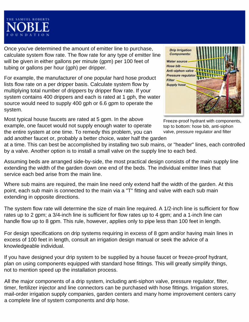
Freeze-proof hydrant with components, top to bottom: hose bib, anti-siphon valve, pressure regulator and filter
Once you've determined the amount of emitter line to purchase, calculate system flow rate. The flow rate for any type of emitter line will be given in either gallons per minute (gpm) per 100 feet of tubing or gallons per hour (gph) per dripper.
For example, the manufacturer of one popular hard hose product lists flow rate on a per dripper basis. Calculate system flow by multiplying total number of drippers by dripper flow rate. If your system contains 400 drippers and each is rated at 1 gph, the water source would need to supply 400 gph or 6.6 gpm to operate the system.
Most typical house faucets are rated at 5 gpm. In the above example, one faucet would not supply enough water to operate the entire system at one time. To remedy this problem, you can add another faucet or, probably a better choice, water half the garden at a time. This can best be accomplished by installing two sub mains, or "header" lines, each controlled by a valve. Another option is to install a small valve on the supply line to each bed.
Assuming beds are arranged side-by-side, the most practical design consists of the main supply line extending the width of the garden down one end of the beds. The individual emitter lines that service each bed arise from the main line.
Where sub mains are required, the main line need only extend half the width of the garden. At this point, each sub main is connected to the main via a "T" fitting and valve with each sub main extending in opposite directions.
The system flow rate will determine the size of main line required. A 1/2-inch line is sufficient for flow rates up to 2 gpm; a 3/4-inch line is sufficient for flow rates up to 4 gpm; and a 1-inch line can handle flow up to 8 gpm. This rule, however, applies only to pipe less than 100 feet in length.
For design specifications on drip systems requiring in excess of 8 gpm and/or having main lines in excess of 100 feet in length, consult an irrigation design manual or seek the advice of a knowledgeable individual.
If you have designed your drip system to be supplied by a house faucet or freeze-proof hydrant, plan on using components equipped with standard hose fittings. This will greatly simplify things, not to mention speed up the installation process.
All the major components of a drip system, including anti-siphon valve, pressure regulator, filter, timer, fertilizer injector and line connectors can be purchased with hose fittings. Irrigation stores, mail-order irrigation supply companies, garden centers and many home improvement centers carry a complete line of system components and drip hose.

A fertilizer injector makes "fertigation" (the application of fertilizer through the drip system) possible.
Components When selecting system components, make sure they are adequate or even necessary. Many name brand manufacturers furnish a do-it-yourself guide to assist with component selection.
Anti-siphon valves are mandatory in most municipalities. Check local ordinances to determine the type of device required.
When selecting a pressure regulator, make sure it is matched with the system operating pressure. Excess pressure can cause rupturing of the emitter lines. Inadequate pressure will result in a lowered flow rate, increasing the time required to water.
Drip systems using city water do not require a filter. However, contamination can occur as the result of water line breaks. Therefore, protect your system by installing a filter having a minimum 150-mesh screen size. If you plan to obtain water from a river, pond or lake, the drip system will require a more sophisticated, and expensive, filter. Consult an irrigation specialist or product representative for details.
A water timer may sound like a good idea, but, if depended on exclusively, can lead to a false sense of security, not to mention poor crop performance. Plants require water based on need, not on any particular schedule. A plant's need changes based on maturity and weather conditions. Therefore, use a timer only as a last resort.
A fertilizer injector is required if you plan on fertilizing. As mentioned earlier, this is the preferred method of fertilizing crops grown under plastic mulch. Before you purchase an injector, make sure it can operate at the low pressure and flow rates common to small garden drip systems. See the
section 'Selection and Use of Fertilizer Injectors' for details.

'Popping' a taut rope against the soil surface to mark the centerline of a bed
Use the centerline as a guide for the emitter line placement.
Placing Emitter Lines Emitter lines may be buried in the beds or placed on the surface, depending on if plastic mulch is used. For best results using plastic mulch, the emitter lines should be buried. Their presence on the soil surface prevents the film from hugging the surface tightly, a condition necessary for rapid and efficient warming of the beds. On unmulched beds, emitter lines may be buried or left on the surface.
Locate emitter line to best accommodate planting configuration. Plan on spacing emitter lines 12 inches apart (6 inches from centerline) when planting one, two or three rows on 40-inch beds. Examples of crops planted on one, two and three rows per bed include tomato, pepper and strawberry, respectively. Plan on spacing emitter lines 18 inches apart (9 inches from centerline) when planting four or more rows per bed. Examples of crops planted four, six and eight rows per bed include lettuce, spinach and carrot, respectively. Refer to Tables 2-A and 2-B for emitter line placement based on planting (row) configuration.
Regardless of how or where emitter lines are spaced, it is critical they be kept straight. Knowing the exact location of emitter lines is possible only if the lines are installed in a straight, precise manner. This will help to avoid damaging buried lines when planting or cultivating. For surface application, use landscape staples or mound soil over the emitter lines at strategic locations to keep them straight.
In cold weather, hard hose emitter tubing can be difficult to work with. To increase flexibility, warm the tubing by exposing it to sunshine.
The easiest method of burying hard hose emitter line is to press the tubing into the soil with your hands. Press the tubing into the soil at least 1 inch. You'll need to dig a trench to bury thin-walled drip tape or if you plan on burying hard hose deeper than 2 inches.

Be sure the soil profile has been shaped and the soil is in a loose, easy-to-crumble condition prior to pressing the tube into place. Once the lines have been installed, go ahead and firm the soil surface in preparation for mulch application.
Installing emitter lines on the surface of unmulched beds has one advantage: if laid out in a straight line, the tubing can be used as a planting guide. Push planters directed alongside emitter lines will insure straight rows of crops. Uniformly spaced drippers permit emitter line to substitute for a measuring tape, providing uniform placement of transplants. Be sure to firm soil prior to surface application of emitter lines.
To prevent the plugging of drippers by foreign material that might have entered the system during installation, be sure and flush emitter lines prior to closing the ends. It's also a good idea to flush mains and header lines prior to attaching emitter lines.
To extend the life of your system, remove the head unit and store out of the elements during cold weather. The emitter lines can be rolled up and stored or left in the beds. If left in place, protect the tubing from sunlight degradation by covering with soil.
To prevent pipes and tubing from bursting during the winter, expel excess water from the system. On small systems, blow water out using your mouth. On larger systems, use a compressed air tank equipped with a hose fitting.
Table 2-A
Emitter Line Placement (1-3 crop rows per bed)
Table 2-B
Emitter Line Placement (4-8 crop rows per bed)

Different colors of mulch films being used at the Noble Foundation Horticulture Center
Plastic mulches have been available since the early 1960s and their popularity has continued to grow. In addition to commercial growers, countless numbers of backyard gardeners have come to appreciate the many advantages plastic mulch provides.
Some of these advantages include the following:
Earlier crops. Most experts consider this to be the single greatest benefit from using plastic mulch. When combined with raised bed culture, plastic mulch acts to raise soil temperature, thereby promoting faster crop development and earlier yields, up to two weeks in some conditions.
Weed control. I consider this to be the second greatest benefit of plastic mulch. For a mulch to be effective, enough light must be blocked to prevent weed growth. An exception is nutgrass, where the nutlike tubers provide enough energy for the seedling to puncture the mulch and emerge.
Reduced evaporation. Soil water loss is reduced under plastic mulch. While mulching insures greater irrigation efficiency, it also necessitates the need for drip irrigation as all moisture falling on the mulched bed, be it from overhead irrigation or rainfall, is shed from the bed.
Reduced fertilizer leaching. Because water runs off the mulch, plant nutrients are not lost through leaching. While plastic mulch does insure greater nutrient use efficiency, it also limits application of dry fertilizer materials, whether processed or natural (organic), prior to applying mulch. Any additional nutrients the crop receives must be applied via the drip system.
Cleaner product. The edible product from a mulched crop is cleaner and less subject to rot because mud from rainfall or irrigation is not splashed on the plants or fruit.
Plastic film mulch is available in several styles and widths. Black plastic is the most popular because it retards weed growth, warms the soil and is relatively inexpensive. White on black mulch provides a cooler soil temperature and is commonly used for establishing such crops as fall tomatoes or cole (cabbage, broccoli, etc.) crops under hot summer conditions.
Clear mulch provides the greatest soil warming potential of any mulch. A drawback of clear mulch is that it promotes weed growth because the plastic is transparent to sunlight. At the Noble Foundation, clear plastic mulch is used religiously during July and August in fallow beds to control weeds and soil-borne pathogens using heat, in a process known as solarization.
The best qualities of both clear and black plastic are available with IRT (infrared transmitting) mulch. IRT mulch transmits infrared radiation to warm the soil similar to clear mulch, but blocks most visible radiation, as does black mulch. IRT mulches are typically translucent green or brown.

Recently, several types of crop-specific, or "designer," mulches have been developed. For example, tomatoes are partial to red mulch while potatoes favor pale blue or white. Squash and eggplant have responded favorably to blue. Research has shown growing tomatoes on red mulched beds, rather than conventional black mulched ones, can increase harvest of quality fruit by 10 to 15 percent.
It's not the colors of the mulch that enhance yield, but the difference the colors make in the light reflected onto the plants.
Research on the effects colored mulches have on plant growth and yields is ongoing. No doubt other colors will be identified as beneficial to certain fruit and vegetable crops, and new products will be offered as research becomes conclusive.
Various types of woven and perforated mulches that are porous to air, water and nutrients also can be used effectively on permanent raised beds. These "weed mat" or "landscape fabric" types of mulches provide excellent weed control and can be used in combination with sprinkler irrigation systems. Their heavier design endows them with several years of service life. Consequently, they are ideally suited for use with perennial crops such as small fruit.
Expect to pay more for porous mulches. Also, don't expect the same soil warming benefit from porous mulches that can be achieved using thinner film mulches.
Plastic mulch film generally comes on rolls 4- to 5-feet-wide. Less common 3- and 6-feet-wide rolls also are available.
Mulch films are available in various lengths with 2400- and 4000-foot rolls most common. Shorter lengths are available from mail order catalogs. See the appendix for a list of companies carrying plastic mulch.
Mulch films are available in either smooth or embossed surface finish. The embossed film hugs the bed better and is not as prone to loosen during warm weather. Expect to pay a little more for embossed film.
Ranging in thickness from 1 to 1.25 mils (1 mil = 1/1000 inch), mulch film is thinner than the woven fabric mulch sold at home improvement centers. Because it is very thin, don't plan on using the mulch for more than one growing season.
Before you decide on the use of plastic mulch as a component of your raised bed gardening system, consider the increased amount of maintenance required. Growing crops on plastic mulch also is a whole new game when it comes to water and nutrient management. A thorough understanding of the use of tensiometers to schedule irrigation and of fertilizer injection equipment to inject nutrients into the drip system is required to realize the full potential of the mulched growing system.

Preparing trenches to bury mulch film
Burying the edges of plastic mulch in pathways using the trench method.
Burying the edges of plastic mulch within the bed using the alternative trench application method.
Most growers would be well advised to master the use of drip irrigation and fertigation (the application of fertilizer through the irrigation system) on unmulched beds before attempting growing crops on plastic mulch. If you are determined to utilize plastic mulch without any previous experience, consult as many references as possible and then use mulch on a limited scale. Seeking the assistance of an experienced grower also would be prudent.
If you intend to use plastic mulch to hasten growth, don't wait until planting to apply it. For spring planting, the mulch should be applied at least seven days before planting to allow time for soil warming.
Beds are ready to receive plastic mulch only when they have been properly prepared. All beds should have pre-plant fertilizer applied, drip irrigation installed, and be crowned, firmed and moist. Never apply mulch to excessively dry beds as the growing medium could settle, allowing mulch to loosen after wetting.
There are two basic methods of applying mulch to permanent beds. One involves wrapping the entire bed profile with plastic and burying the edges of the mulch film in trenches dug along the edge of the bed borders. The other method utilizes wood lath to secure the film to the bed borders.
The trench method of mulch application is ideally suited for use with recycled auto tire beds and plastic mesh beds. A 40-inch-wide bed requires a 6-foot-wide roll of mulch to wrap the entire bed and provide enough excess to adequately bury edges in the pathways.
If the pathways are too water-soaked to accommodate digging trenches, consider burying the edges of the mulch in trenches dug along the interior edge of the bed borders. A 4-foot roll of mulch is ideally suited to this technique when applied to 40-inch beds.

When preparing trenches, be sure they are of sufficient width and depth to securely hold the edges of the mulch when soil is replaced. Use a garden hoe to prepare 6-inch-wide by 3-inch-deep trenches in the pathways next to the bed. If the soil in the pathways is tight or compacted, a tiller is used to loosen it prior to trenching.
When preparing trenches along the interior edge of the borders, use a square-point shovel to carve out 4-inch-wide by 6-inch deep trenches.
While effective, the process of digging trenches to bury mulch film requires considerable time and energy. In an effort to make mulch application more user friendly, we developed a technique that uses short pieces of wood lath to attach the film to the bed.
To apply mulch film to an auto tire bed using the lath technique, start by installing a single 1-inch hex head sheet metal screw into each pocket, placing the screws in the middle and 1 inch below the top of the pocket. Do not fully insert the screws at this time, just get them
started.
You will also need to prepare 1-inch-wide by 6-inch-long lath made from 1/4-inch plywood. Plywood is preferred over other types of wood lath because it resists splitting when screws are used. Prepare one piece of lath for every pocket. A single 4-foot by 8-foot sheet of plywood will supply 268 pieces of lath.

Roll of mulch film mounted on stands for easy unrolling
Unroll the mulch film using one of the following methods:
Traveling roll – Place the roll of mulch at one end of the bed. Place a weight, such as a concrete block, on the free end of the roll to hold the film to the ground. Insert a pipe through the roll. Pick up the roll by the pipe "handles" and walk to the other end of the bed, unrolling the film as you go. This method requires two people.
Stationary roll – This method involves placing the pipe handles on portable stands at one end of the bed. Walk the
loose end of the film to the opposite end, unrolling the film as you go. This method requires only one person (although two is preferred) and is easier on the back.
Wrap several times for extra strength.
Inserting lath behind pocket
Securing lath to bed wall
Stretch film for a tighter fit.
Attach the free end of the film to the end of the bed using the lath pieces. Working with one piece of lath at a time, wrap the film around the lath, pull the top of the rubber pocket away from the bed and insert the lath behind the pocket. Releasing the pocket top should lock the lath in place. Secure the lath to the pocket using the preinstalled hex head screws.
Proceed to the other end of the bed. Cut the film from the roll, leaving an extra foot of film to work with. Repeat the fastening process on this end. As you roll the film around the lath, pull the film

Attaching film to both sides of bed
towards you to remove any slack. Don't overstretch the film because tearing could occur.
Using the same pocket and lath technique, attach film to both sides of the bed, stretching the film crossways to remove any slack prior to attaching.

Plastic mulch applied to a recycled auto tire bed using the lath technique
"Rolling out" mulch film
Use a minimum of four pieces of lath to attach mulch film to the end of bed.
Placement of lath on frame between stakes
To remove the film, back the hex head screws out of the pockets until the lath pieces are released. Collect the lath pieces and store them in a dry location to prevent warping. Dispose of the mulch film in a responsible manner. Leave the hex head screws in the pockets where they will be ready for service the next time film is applied.
Applying plastic mulch to a corrugated sheet metal bed using the lath technique is similar to an auto tire bed with a few differences.
Begin by unrolling the mulch film using one of the two methods previosly described.
Attach the free end of the film to the end of the bed using the lath pieces. Working with one piece of lath at a time, wrap the film around the lath, pull the film over the top of the bed and attach the lath to the side of the 2-inch by 4-inch frame using 1-inch hex head screws. Space the lath pieces 1 foot apart.
Proceed to the other end of the bed. Cut the film from the roll, leaving an extra foot of film to work with. Repeat the fastening process on this end. As you roll the film around the lath, pull the film towards you to remove any slack. Don't overstretch the film because tearing could occur.
Using the same lath technique, attach film to both sides of the beds, stretching the film crossways to remove any slack prior to attaching. Attach the film to the portion of the wood frame located between the sucker rod stakes.

A helpful tip when applying mulch on a windy day: if at all possible, walk with the wind while unrolling the film, keeping the film as low as possible. The first time the mulch goes airborne, you'll appreciate the advice.
Depending on how you've configured the drip irrigation, you possibly will need to cut a hole in the mulch to accept the drip supply line feeding one end of the beds.
After removing the plastic mulch, collect the hex head screws or simply reinsert them into the wood frame. Remember to store the wood lath in a dry place when it's not in use.
A few closing comments on the use of mulch film. While black plastic mulch is recommended for use on spring planted crops, problems can arise if used in conjunction with summer plantings. In the southern U.S., the extreme heat generated with the use of black plastic mulch exerts tremendous stress on young seedlings.
During summer months, some growers substitute white or silver-colored mulch for black. These lighter colored films are more efficient in reflecting sunlight, thus preventing excessive heat buildup in the beds. They are commonly used for establishing such crops as fall tomatoes or cole (cabbage, broccoli, etc.) crops under hot summer conditions.
Organic materials offer an effective alternative to plastic for summer mulching. At the Noble Foundation, we mulch all of our summer plantings with compost. Summer use of organic mulch offers all the advantages common to plastic mulch, plus it constitutes a source of slow-release fertilizer. When incorporated into the soil, organic mulch increases the water and nutrient holding capacity of the soil and improves soil tilth.

A set of template row markers with stakes attached
Anchoring a template to one end of a bed after centering on bed
Before planting your raised bed garden, refer to tables 1 and 2. Table 1 lists inter- and intra-row vegetable plant spacings developed specifically for 40-inch-wide beds. If your beds are equipped with buried drip irrigation, determine the location of the emitter lines prior to marking rows. Refer to Table 2 (A and B) for the proper emitter line placement for various row spacings.
Several techniques are available for marking planting rows. The oldest method used to ensure a straight row is a taut string between two stakes. The template row marker is a modification of this simple technique and is ideal for quickly and accurately marking multiple rows per bed.
The template row marker consists of a matching set of wooden templates and a rope marker. Each template is equipped with an array of screws (or nails) that correspond to the location of a row on the bed. Use the calibration guide in Figure 1 and a permanent marker to properly locate and label each screw on the templates. Leave 1/4 inch of the shank exposed when inserting the screws into the templates so the rope can be attached.
When ready to mark rows, position the templates at both ends of the bed. To prevent movement, use rebar stakes to anchor each template to the bed surface. Remember to center the template on the bed before anchoring.
Attach the looped ends of the rope (clothesline works well) to the corresponding screws on each template. When attached, the rope should be taut. Lifting and releasing, or "popping", the rope several times will leave an indention in the soil surface, which marks the rows and doubles as a furrow for hand-sown small seeds.
Using a template row marker on a plastic mulched bed by substituting chalked line for rope
Marking a row by popping line

Use a bolt and a wing nut to make the template set transportable.
If you have an exceptionally large garden and desire a quicker mothod of marking rows, consider constructing a rolling row marker. Our marker, similar to that cited by Eliot Coleman in his book "The New Organic Grower", can be constructed for less than $40. It uses a series of wheels to mark each row simultaneously as it is pulled over the bed surface.
The Noble Foundation's rolling marker consists of a series of eight 7 5/8-inch-diameter wheels mounted on a 3-foot-long piece of 5/8-inch-diameter threaded rod. The wheels are cut from 1/2-inch plywood and mounted on the threaded rod axle through their centered 5/8-inch-diameter holes. Tightened nuts on either side of the wheels prevent them from moving off their designated settings.

Dimensions of the Noble Foundation rolling row marker
Cotter pin used to secure threaded rod to axle body
Close up of rolling marker
Mounting additional marking wheels onto axle
The ability to lock two or more wheels in any position along the length of the axle simply by tightening and loosening nuts is what makes this design so versatile. As with the template row marker, the rolling marker must be calibrated for use on 40-inch-wide beds. Use the calibration guide and a permanent marker to locate and label wheel settings on
the face of the axle body.
Consider using a wood preservative to extend the life of your rolling row marker and minimize wheel warping. For extra protection, apply a coat of polyurethane, especially to the wheels.
Rolling Row Marker Parts DescriptionAmt. Item Size Price
1 Board 1" x 6" x 8' $3.001 Plywood 1/2" x 2' x 4' $8.0020 Eye screws 1/8" eye opening $1.0016 Nuts 5/8" $5.0018 Washers 5/8" $5.001 Threaded rod 5/8" x 3' $3.501 Galvanized wire No. 10 x 6' $0.5020 Wood screws No. 10 x 1 1/2" $2.002 Cotter pins 1/8" x 2" $0.20
Total $28.20

Crosschecking rows with a rolling marker equipped with crosswires
An opened eye screw is used to lock the cross wire into place.
When equipped with crosswires, the rolling row marker can be used to mark planting locations in the rows. Mounting two crosswires opposite each other on the forward edges of the wheels enables the rolling marker to crosscheck each row every 12 inches. The straight pieces of No. 10 galvanized wire are attached to the wheels by means of eye screws. "Opened" eye screws inserted into the outer surface of one of the outside wheels are used to lock in the crosswires, which can be removed simply by pushing the bent ends out from under the screws and
sliding them free.
To ensure straight rows, keep the rolling marker centered on the bed. Try using the bed borders as a visual guide. If the borders are straight, your rows will be straight.
If you are a neatness freak, you will want to space plants uniformly in the rows. Marking planting sites with a measuring tape is fine in small gardens, but can quickly become a chore in larger ones. To make this job quick
and easy, consider constructing a plant locator.
An assembled and ready to use plant locator
A plant locator consists of four pieces of 1-inch by 2-inch treated lath and a few nuts and bolts. Our plant locator is calibrated for plant spacings of 12, 18 and 24 inches. It works well on both unmulched and plastic mulched beds. Once you have used this tool, you will never consider using a measuring tape again. The legs of the locator accurately mark planting sites when the device is walked downa row.
Cross member of a plant locator calibrated for 12-, 18- and 24-inch spacings
"Walking" a plant locator down a row to mark planting sites
A plant locator makes easy work of marking planting sites on plastic mulch.

An Earthway garden seeder
A Cole Planet Jr. push planter
If you are looking for a quick and easy way to seed your beds, consider purchasing a push planter. Several models are priced for the home and market gardener. The Earthway Garden Seeder, priced around $100, is the most popular. It comes equipped with several seed plates, giving it the capability of planting both small and large seed. Because of its lightweight design, the seedbed must be in good tilth and free of clods and plant debris, which have a tendency to ball up in front of the furrow opener and push the seeder out of the soil.
The Cole Planet Jr. vegetable seeder, priced around $500, is designed with the market gardener in mind. The steel construction allows it to take plenty of abuse and increases its weight, permitting this push planter to perform well in soil containing greater amounts of debris.
For best results sowing small-seeded crops such as carrot, lettuce, onion, radish and spinach consider purchasing a Glaser seeder, which works only on finely tilled, debris-free soil surfaces. The single row model is available for around $125.
Contact local garden centers or consult mail order garden supply catalogs for availability of these planters and others.
When setting plants through plastic mulch, use a bulb planter for preparing holes for standard size transplants. For plants grown in 4-inch or larger containers, use a post hole digger or a similar sized tool to prepare planting holes. Keeping the forward edge of these tools sharp will ensure a precise cut with minimal stretching and tearing of the plastic.
To get your transplants off to a good start, water them with a soluble fertilizer solution high in phosphorous.
For more information on scheduling planting dates for your area, contact your local county extension office.

A bed successfully planted using a push planter
Preparing planting holes for strawberry transplants
Tools for digging transplant holes: left, a bulb planter; middle, a customized soil extractor made from electrical conduit and thin-walled pipe; right, a post hole digger
The Glaser seeder is ideal for small seeded crops.

Table 1. Vegetable Plant Spacing for 40"-Wide Beds Constructed on 60" (5-ft.) Centers
CropNo. of Rows/
BedSpacing between
Rows (inches)
Final Spacing in the Rows1
(inches)Asparagus 2 18" 18"Bean, bush 2 18" 4"Bean, pole 2 18" 12"Beet 8 4.5" 4"Broccoli 2 18" 18"Brussels sprouts 2 18" 18"Cabbage 2 18" 18"Cantaloupe/Muskmelon 1 NA 24"Carrot 8 4.5" 2"Cauliflower 2 18" 18"Collard 2 18" 18"Cucumber 1 NA 12"Eggplant 1 NA 24"Kale 2 18" 18"Kohlrabi 4 9" 6"Leek 4 9" 4"Lettuce, butterhead and romaine 4 9" 8"Lettuce, crisphead 4 9" 10"Lettuce, leaf 4 9" 6"Mustard greens 3 12" 6"New Zealand spinach 2 18" 12"Okra 1 NA 12"Onion, bulb 4 9" 4"Onion, green 8 4.5" 1"Pea, dwarf 2 18" 4"Pea, vining 2 18" 12"Pepper 2 18" 18"Potato 1 NA 12"Pumpkin, standard size2 1 NA 36"Radish 8 4.5" 2"Southern pea, bush 2 18" 4"Southern pea, semivining 1 NA 8"Spinach 6 6" 6"Squash, bush 1 NA 24"(yellow and zucchini)

Squash, vining 1 NA 36"(butternut, acorn and hubbard)Strawberry 3 12" 18"Sweet corn 2 18" 12"Sweet potato 1 NA 12"Swiss chard 2 18" 12"Tomato 1 NA 24"Turnip 4 9" 4"Watermelon, standard size2 1 NA 36"1 Many small-seeded crops, such as leafy greens, can be harvested while still immature. Oversow thick, then thin to desired spacing and enjoy fresh produce in the process! 2 Because of large vines, plant every other bed. Also consider planting crop at the edge of the garden to reduce competition with other crops.

Table 2a. Emitter Line Placement (1-3 crop rows per bed)
Table 2b. Emitter Line Placement (4-8 crop rows per bed)
Figure 1.
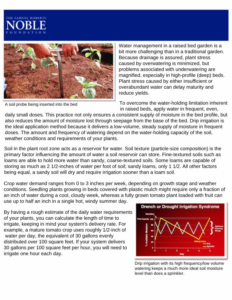
A soil probe being inserted into the bed
Water management in a raised bed garden is a bit more challenging than in a traditional garden. Because drainage is assured, plant stress caused by overwatering is minimized, but problems associated with underwatering are magnified, especially in high-profile (deep) beds. Plant stress caused by either insufficient or overabundant water can delay maturity and reduce yields.
To overcome the water-holding limitation inherent in raised beds, apply water in frequent, even, daily small doses. This practice not only ensures a consistent supply of moisture in the bed profile, but also reduces the amount of moisture lost through seepage from the base of the bed. Drip irrigation is the ideal application method because it delivers a low-volume, steady supply of moisture in frequent doses. The amount and frequency of watering depend on the water-holding capacity of the soil, weather conditions and requirements of your plants.
Soil in the plant root zone acts as a reservoir for water. Soil texture (particle-size composition) is the primary factor influencing the amount of water a soil reservoir can store. Fine-textured soils such as loams are able to hold more water than sandy, coarse-textured soils. Some loams are capable of storing as much as 2 1/2-inches of water per foot of soil; sandy loams, only 1 1/2. All other factors being equal, a sandy soil will dry and require irrigation sooner than a loam soil.
Drip irrigation with its high frequency/low volumewatering keeps a much more ideal soil moisture level than does a sprinkler.
Crop water demand ranges from 0 to 3 inches per week, depending on growth stage and weather conditions. Seedling plants growing in beds covered with plastic mulch might require only a fraction of an inch of water during a cool, cloudy week, whereas a fully grown tomato plant loaded with fruit can use up to half an inch in a single hot, windy summer day.
By having a rough estimate of the daily water requirements of your plants, you can calculate the length of time to irrigate, keeping in mind your system's delivery rate. For example, a mature tomato crop uses roughly 1/2-inch of water per day, the equivalent of 30 gallons evenly distributed over 100 square feet. If your system delivers 30 gallons per 100 square feet per hour, you will need to irrigate one hour each day.

Top, removing soil from the probe; middle, squeezing the sample by hand; bottom, hand showing wet outline of soil
Using stage of growth and weather conditions to schedule irrigation is a calculated guess at best. A better method is to evaluate the soil moisture condition by either sampling with a soil probe or short piece of thin-walled pipe or installing a soil-moisture-measuring instrument. The probe should be inserted into the bed 6 to 12 inches from the base of the plant, where roots are actively growing, or for closely spaced crops, in the plant row. To avoid cutting drip emitter lines, determine their locations before inserting the probe.
Nearly all garden crops grown under irrigation extract water from the top 2 feet of the soil profile. In fact, up to 95 percent of the roots are in the top 12 inches, so it isn't necessary to sample below a 12-inch depth when you use a soil probe.
You can estimate available soil water by appearance and touch. To estimate moisture content, remove a handful of soil from the probe and squeeze very firmly with your fingers. If the soil ball is squeezed immediately following an irrigation or heavy rain, water will drip from it. If this high level of moisture persists, plant health and performance could suffer, but if you're growing plants in raised beds, excessive moisture shouldn't be a problem. The ideal soil moisture content is indicated when, upon being squeezed, the soil ball emits no free water and only a wet outline of the ball remains on your hand. If there is no outline, the soil is dry and should be irrigated. Although measuring soil water by appearance and feel is not precise, with experience and judgment, you should be able to schedule irrigation with a reasonable degree of accuracy.
A more accurate method of measuring soil moisture to schedule irrigation involves the use of a tensiometer, a device that measures how tightly water is held in the soil which is an indirect indication of soil moisture content. A tensiometer consists of a sealed water-filled tube equipped with a vacuum gauge on the upper end and a porous ceramic tip on the lower end. As the soil around the tensiometer dries, water is drawn from the tube through the ceramic tip, creating in the tube a vacuum or tension that can be read on the gauge. When the soil water content is increased through rainfall or irrigation, water enters the tube through the porous tip, lowering the gauge reading.

A tensiometer
A gauge face showing centibar graduations
Top, making hole slightly smaller than tensiometer shaft diameter for a snug fit; middle, filling the hole with water; bottom, inserting the tensiometer, making sure it is well seated. Do not use excessive force.
Soil tension levels used to schedule irrigation vary with soil texture. In a sandy loam, irrigation should begin when soil tension reaches 20 centibars (a unit of pressure) and cease when it falls to 10 centibars. A soil tension reading of 0 indicates complete saturation. In a finer-textured soil such as silt loam, there is no need to irrigate until soil tension reaches 30 centibars.
Insert the tensiometer as you would a probe, 6 to 12 inches from the base of the plant or in the row if crops are closely spaced.
Expect to spend extra time at first to learn how the tensiometer reacts to various weather and cropping situations. With time, you will be able to schedule irrigations to achieve the desired soil moisture response.
Tensiometers come in various lengths. The 6-inch model is ideal for use in raised beds. Although not required, a 12-inch model placed alongside the 6-inch tensiometer helps determine the depth of water penetration so that water won't be wasted.
Because of their cost ($50 to $60 for a 6-inch model), it is impractical to place a tensiometer in every bed or crop. If you have only one tensiometer, locate it among plants having the greatest water demand (tomatoes would be the candidate in most
gardens). Adjust irrigation to match water requirements of other crops accordingly.
For information on the use and care of your tensiometer, refer to the owner's manual. With proper care, a tensiometer can provide many years of useful service. For a list of tensiometer (also called an irrometer) merchandisers, refer to the appendix. Following these guidelines will help you manage your water resource. Proper scheduling of irrigation will help ensure maximum production with minimum watering.

Table 3 Topdressing with Nitrogen FertilizerRate: 1/3 - 1/2 lb 34-0-0/100 sq ft
Crop Time Beans Flowering Broccoli, Cabbage, Cauliflower 3 weeks after transplanting Cucumber and Cantaloupe Vines begin to run Okra Flowering Greens (Spinach, Lettuce, Collard) 3 weeks after emergence Sweet Corn 1-foot high Tomato, Pepper, Eggplant Golf ball size fruit Watermelon and Squash When yield drops
During seedbed preparation, any nutrient deficiencies should be corrected with fertilizer. Regardless of whether you use an organic or chemical (granular) fertilizer, the application should be based on a soil test report. Contact your local county or state Cooperative Extension office for information on soil testing.
With the exception of nitrogen, all the recommended nutrients should be applied during bed preparation. Only a portion (30 to 40 percent) of the crop's total nitrogen requirement should be present in the soil at planting because too much nitrogen applied prior to planting can result in delayed fruiting. For most vegetable crops, this portion is equivalent to 40 to 50 pounds of actual nitrogen per acre, enough to get your garden off to a good start. If a nitrogen deficiency is reported, consult your soil test report for a pre-plant nitrogen fertilizer recommendation.
Typically, additional nitrogen is supplied by one or more fertilizer applications over the life of the crop. Fertilizer should be applied to the soil surface around plants (topdressed) at critical stages of crop growth. For a few vegetable crops, Table 3 lists topdressing times based on stage of growth.
Although topdressing addresses the problem of overfertilization, it does have limitations, the most obvious being its incompatibility with plastic mulch. The plastic film acts as a barrier to the fertilizer. Second, the practice of topdressing is not calibrated to the nitrogen requirement (growth curve) of plants. Figure 2 illustrates the relationship of a crop's nitrogen requirement to its stage of development or growth curve. Early in the life of a crop, plants are small and devoid of fruit; their requirement for nitrogen is limited. As plants grow, their demand for and ability to use nitrogen increase, peaking during reproduction (fruiting).
Matching fertilizer application to a crop's growth curve is a far better way to fertilize and is best accomplished by using your drip irrigation system to deliver small, frequent doses of soluble fertilizer to the plant's root system, a process referred to as fertigation. Under plastic, drip fertigation permits precise nutrient placement with less waste.

Figure 2
The one disadvantage of drip fertigation is the need for multiple applications of fertilizer. Ideally, crops should be fertilized no less than once a week, a routine that has yielded excellent results at the Noble Foundation. Plan on designating one day of the week as "feeding" day.
A fertigation schedule for 16 popular vegetable crops is given in Table 4 and was developed by researchers at the University of Florida for the commercial vegetable industry. We have modified it
for garden use.
Note this about the schedule: it was designed to be used as a guide only. The fertilizer rates have been developed for crops grown on plastic-mulched raised beds composed of sandy soils low in organic matter. If a soil test-based pre-plant fertilizer application has been made or if the soil test indicates sufficient levels of all plant nutrients, the first two scheduled nitrogen applications may be omitted. Ammonium nitrate (34-0-0) is the most readily available form of soluble nitrogen. In the absence of a pre-plant fertilizer application, use a soluble form of a complete fertilizer such as Miracle-Gro 18-18-21, Rapid-Gro or Peter's.
When using this schedule on soils amended with large quantities of organic materials, expect to lower the scheduled rate according to (1) nitrogen content of the material (compost is an excellent source of nitrogen, while peat moss is a poor one); (2) stage of decomposition (nitrogen is more readily available from a well-decomposed source of organic matter, such as compost, than from raw animal manure or lawn clippings); and (3) soil temperature (as soil temperature increases, the rate of decomposition increases, thereby increasing the availability of nitrogen).
In certain situations in which organic soil amendments are used, little if any additional nitrogen will be required. Normally, several trials are needed to fine-tune this schedule to a particular practice. Regular soil testing, in combination with careful observation and note taking, will help you control nutrient management.
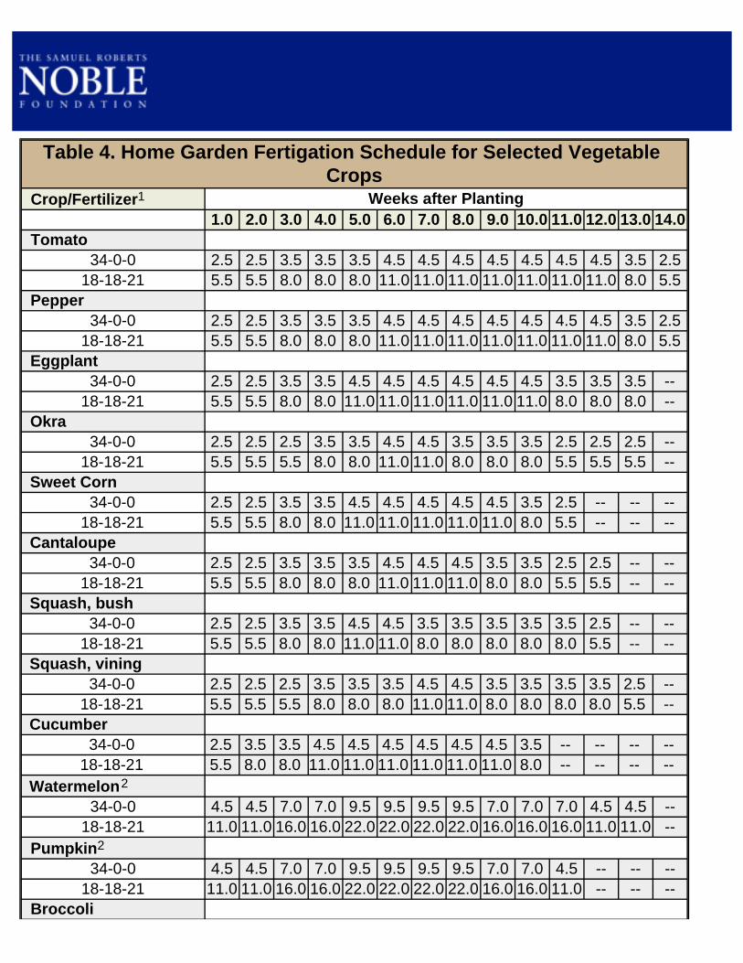
Table 4. Home Garden Fertigation Schedule for Selected Vegetable Crops
Crop/Fertilizer1 Weeks after Planting1.0 2.0 3.0 4.0 5.0 6.0 7.0 8.0 9.0 10.0 11.0 12.0 13.0 14.0
Tomato34-0-0 2.5 2.5 3.5 3.5 3.5 4.5 4.5 4.5 4.5 4.5 4.5 4.5 3.5 2.5
18-18-21 5.5 5.5 8.0 8.0 8.0 11.0 11.0 11.0 11.0 11.0 11.0 11.0 8.0 5.5 Pepper
34-0-0 2.5 2.5 3.5 3.5 3.5 4.5 4.5 4.5 4.5 4.5 4.5 4.5 3.5 2.518-18-21 5.5 5.5 8.0 8.0 8.0 11.0 11.0 11.0 11.0 11.0 11.0 11.0 8.0 5.5
Eggplant34-0-0 2.5 2.5 3.5 3.5 4.5 4.5 4.5 4.5 4.5 4.5 3.5 3.5 3.5 --
18-18-21 5.5 5.5 8.0 8.0 11.0 11.0 11.0 11.0 11.0 11.0 8.0 8.0 8.0 -- Okra
34-0-0 2.5 2.5 2.5 3.5 3.5 4.5 4.5 3.5 3.5 3.5 2.5 2.5 2.5 --18-18-21 5.5 5.5 5.5 8.0 8.0 11.0 11.0 8.0 8.0 8.0 5.5 5.5 5.5 --
Sweet Corn34-0-0 2.5 2.5 3.5 3.5 4.5 4.5 4.5 4.5 4.5 3.5 2.5 -- -- --
18-18-21 5.5 5.5 8.0 8.0 11.0 11.0 11.0 11.0 11.0 8.0 5.5 -- -- -- Cantaloupe
34-0-0 2.5 2.5 3.5 3.5 3.5 4.5 4.5 4.5 3.5 3.5 2.5 2.5 -- --18-18-21 5.5 5.5 8.0 8.0 8.0 11.0 11.0 11.0 8.0 8.0 5.5 5.5 -- --
Squash, bush34-0-0 2.5 2.5 3.5 3.5 4.5 4.5 3.5 3.5 3.5 3.5 3.5 2.5 -- --
18-18-21 5.5 5.5 8.0 8.0 11.0 11.0 8.0 8.0 8.0 8.0 8.0 5.5 -- -- Squash, vining
34-0-0 2.5 2.5 2.5 3.5 3.5 3.5 4.5 4.5 3.5 3.5 3.5 3.5 2.5 --18-18-21 5.5 5.5 5.5 8.0 8.0 8.0 11.0 11.0 8.0 8.0 8.0 8.0 5.5 --
Cucumber34-0-0 2.5 3.5 3.5 4.5 4.5 4.5 4.5 4.5 4.5 3.5 -- -- -- --
18-18-21 5.5 8.0 8.0 11.0 11.0 11.0 11.0 11.0 11.0 8.0 -- -- -- -- Watermelon2
34-0-0 4.5 4.5 7.0 7.0 9.5 9.5 9.5 9.5 7.0 7.0 7.0 4.5 4.5 --18-18-21 11.0 11.0 16.0 16.0 22.0 22.0 22.0 22.0 16.0 16.0 16.0 11.0 11.0 --
Pumpkin2
34-0-0 4.5 4.5 7.0 7.0 9.5 9.5 9.5 9.5 7.0 7.0 4.5 -- -- --18-18-21 11.0 11.0 16.0 16.0 22.0 22.0 22.0 22.0 16.0 16.0 11.0 -- -- --
Broccoli

34-0-0 3.5 3.5 3.5 4.5 4.5 6.0 6.0 4.5 4.5 -- -- -- -- --18-18-21 8.0 8.0 8.0 11.0 11.0 13.5 13.5 11.0 11.0 -- -- -- -- --
Cauliflower34-0-0 3.5 3.5 3.5 4.5 4.5 6.0 6.0 4.5 4.5 -- -- -- -- --
18-18-21 8.0 8.0 8.0 11.0 11.0 13.5 13.5 11.0 11.0 -- -- -- -- -- Collards
34-0-0 3.5 3.5 3.5 4.5 4.5 4.5 4.5 4.5 4.5 -- -- -- -- --18-18-21 8.0 8.0 8.0 11.0 11.0 11.0 11.0 11.0 11.0 -- -- -- -- --
Cabbage34-0-0 3.5 3.5 3.5 4.5 4.5 6.0 6.0 4.5 4.5 -- -- -- -- --
18-18-21 8.0 8.0 8.0 11.0 11.0 13.5 13.5 11.0 11.0 -- -- -- -- -- Lettuce
34-0-0 3.5 3.5 4.5 6.0 6.0 6.0 6.0 4.5 -- -- -- -- -- --18-18-21 8.0 8.0 11.0 13.5 13.5 13.5 13.5 11.0 -- -- -- -- -- --
1 Fertilizer rates (level tablespoon) per 100 square feet (40-inch by 30-foot bed). 2 Because vines are large, plant every other bed. Do not fertilize unplanted beds because the amount of nutrients received by planted beds will be reduced.

A brass siphon mixer injector
Once you've decided to fertigate your garden, you should select a fertilizer injector. An injector is required to add the fertilizer to the system. Whether you have one bed or a hundred, there is a suitable model. The price of injectors ranges from a few dollars to several thousand. Fortunately, the less expensive models are compatible with most small-scale drip irrigation systems. The least expensive injector is the brass siphon mixer, which is sold under various brand names and is available at most garden centers and nurseries for around $15 to $20.
The siphon mixer is nothing more than a suction device. As water flows through the tapered orifice within the siphon mixer, the velocity rapidly increases, creating a vacuum that siphons the fertilizer concentrate from a tank or bucket into the system.
Although reasonably priced, brass siphon mixers have limitations. They are designed to be coupled with watering wands and sprinklers having flow rates of 3 gallons per minute (gpm) or higher, far in excess of many backyard drip systems' flow rates. Before purchasing a siphon mixer, determine the flow rate of your system. If your drip system delivers between 1/2 and 3 gpm, consider using a Grow Pro brand injector which costs around $30. Unlike the siphon mixer, the Grow Pro has a built-in 12-ounce reservoir that you fill with a concentrated fertilizer solution before use. The existing water pressure forces the concentrate into the system and exhausts it in 50 gallons of flow. Models capable of handling higher flow rates are also available. (See the appendix for a listing of companies carrying Grow Pro and Add-It injectors.) The EZ FLO injector operates on a similar principle as the Grow Pro injector. A small amount of irrigation water is diverted through the fertilizer tank where it mixes with soluble fertilizer before being injected into the irrigation system. The EZ FLO is an upgrade over the Grow Pro as it is equipped with an adjustable injection rate control. EZ FLO injectors are available in 3/4-, 1 1/3- and 3-gallon models. The 3/4-gal model is priced around $70 which includes a faucet switching kit. The switching kit is recommended for folks who need a quick way of switching out the injector from one drip system to another. (See the appendix for a listing of companies carrying EZ FLO injectors.)

Grow Pro fertilizer injector
An EZ FLO injector equipped with a faucet switching kit
A fourth type of injector compatible with both small and large drip systems can be assembled from a new or used pump-up hand sprayer and a few pipe fittings for under $50. This contraption, affectionately referred to as the "pump-it" injector, relies on air pressure generated by the hand-operated pump to force fertilizer concentrate into the system.

Because fertilizer is corrosive, choose a sprayer that has a polyethylene tank and a pump housing made entirely of plastic. For the typical backyard garden, a 1-gallon sprayer will suffice. A 3-gallon sprayer is recommended for gardens larger than 1,000 square feet.
Before operating the pump-it injector, fill the tank with the desired amount of fertilizer concentrate. Insert the pump into the tank and tighten the handle. Insert the injector manifold into the head assembly of the drip system, making sure the manifold ball valve is closed prior to turning on the system. Once the system is
fully charged, pressurize the tank by using the hand pump. When you are ready to inject the concentrate, simply open the ball valve and adjust it to control the injection rate. The vacuum breaker adjacent to the ball valve prevents irrigation water from entering the tank if the tank pressure falls below the system's operating pressure.
"Pump-It" Fertilizer Injector Parts Description Part Price 3-Gallon Polyethylene Hand Sprayer $25.00 Brass Quick-Connect Set $6.00 1/2-Inch Galvanized Tee $0.60 1/2-Inch MPT x 3/4-Inch MHT Brass Adapter $2.00 1/2-Inch MPT x 3/4-Inch FHT Brass Adapter $2.00 1/2-Inch MPT x 3/4-Inch FHT Brass Adapter $2.00 3/4-Inch MHT x 3/4-Inch FHT Plastic Ball Valve $1.60 3/4-Inch MHT x 3/4-Inch FHT Plastic Vacuum Breaker $3.00 3/4-Inch MHT x 1/2-Inch FPT Brass Adapter $2.00 1/2-Inch MPT x 1/4-Inch FPT Brass Adapter $1.25 1/4-Inch MPT x 1/4-Inch Barb Adapter $1.70 Teflon Tape $1.50 Total $48.65

The disadvantage of the pump-it injector is that emptying the tank can require several pressurizations, the number of pumping strokes depending on the pressure differential between the tank and the system, the volume of concentrate in the tank and the desired rate of injection.
Don't try to force all of the concentrate into the system rapidly; rather, attempt to inject fertilizer at a uniform rate over a 30-minute period. While operating the injector, take time to inspect your garden, catch up on a few chores, visit with your next door neighbor, or perhaps meditate on the meaning of life. After each use, be sure to rinse the tank thoroughly, fill it with clean water and flush the hose and manifold.
At the Noble Foundation, we have used the brass siphon, Grow Pro, EZ FLO and our homemade pump-it injector successfully. Regardless of the model you select for your system, the injector must be installed below (downstream of) the head assembly vacuum breaker or check valve and ahead (or upstream) of the filter.
When using an injector, always wait until the system is fully charged before injecting fertilizer. When finished fertigating, run the system for a few more minutes to flush any remaining fertilizer out of the system.

Freeze damage to a young cucumber plant
A question I often ask tour groups at the Noble Foundation Horticulture Center is, "Why doesn't Oklahoma have a horticultural industry rivaling that of California's Central Valley?" Some common responses include lack of irrigation, markets, labor, poor soil and a short growing season. Although all of these have some legitimacy, they are not paramount. The single greatest deterrent to sustainable horticulture in Oklahoma is extreme weather.
The Horticulture Center was developed in part to address the problems gardeners face in extreme weather regions. During the mid-1990s, our emphasis shifted from researching and demonstrating the benefits of permanent raised beds to addressing weather-based problems, primarily temperature-related ones.
In response to these problems, horticultural researchers have joined forces with plastic film manufacturers to develop protective covers for both commercial and hobby gardens.
There are two types of plastic crop covers. The first consists of polyethylene film supported on frames or hoops to form a tunnel over a row or bed. The second is a fabric-like polypropylene material that floats or can rest directly on the crop. The edges of both kinds of cover are anchored in the soil to combat wind.
The polyethylene row covers are generally cheaper, but more labor-intensive because of the support structure. They create higher daytime temperatures, which is desirable for early- and late-season production, but require venting to control heat buildup on warm, sunny days. Some manufacturers offer row covers with preinstalled slits or circular perforations for automatic venting. Some even offer pigmented (opaque) covers for added cooling. The standard width for row covers is 6 feet.
Because of their porous, lightweight design, floating covers are self-venting and usually don't require a support structure, making them more versatile than row covers. Their width varies from about 6 feet up to about 60 feet, large enough to cover an entire garden. However, if whipped by high winds, floating covers can injure young seedlings. If your garden is exposed, consider using a support structure or erecting a windbreak.
Fibrous nature of floating covers

Opaque and clear slitted covers
Providing additional ventilation by cutting open the row cover supported by re-mesh wire
Tomato leaf protruding through vent slits
Floating cover protecting a 30-foot by 60-foot raised bed plot
Floating covers have a variety of functions based on the weight of the fabric. Lightweight covers are used primarily for insect exclusion; heavier covers are used for elevating day and night temperature; and the heaviest material is used for frost control.
Don't expect crop covers to save your plants from heavy freezes. Row covers and medium-weight floating covers will keep the temperature only 2° to 3°F warmer than the ambient (outside) air. Wind speed and soil temperature influence the degree of protection achieved.
The major benefit of crop covers is their overall growth-enhancing characteristic when used in cool weather. Crops planted one to two weeks ahead of the normal time can mature three weeks early.
Particular attention must be given to cover removal. Depending on the crop and the environmental conditions, row covers can be left in place for about a month. Floating covers can remain in place longer because of their ventilation. Most of the heavier floating covers used for frost control are removed during the day.

Top, heavyweight floating cover used for frost protection; bottom, floating cover removed from flowering cantaloupe
Yields of wind-pollinated crops such as tomato, pepper and eggplant can be reduced if covers are left on too long. Temperature under the covers should not exceed 90°F for more than a few hours during the flowering stage. For crops requiring bee pollination such as squash, cucumbers and melon, the covers should be removed when female flowers appear.
Row covers not only enhance crop development but also hasten weed growth. Because of the impracticality of weeding under crop covers, you should use plastic mulch as well. You can't beat this combination for maximum crop growth and weed control.
If you're interested in taking crop protection to the next level, consider constructing a hoop house, whose primary advantage is convenience. You don't have to remove a cover to gain access to your plants; you simply walk in!
Hoop houses are generally Quonset-shaped structures constructed of metal or plastic hoops. They are covered with a single layer of 6-mil greenhouse-grade polyethylene film and are vented by rolling up the sides. There is no permanent heating system, and there are no electrical connections. The ends of the houses are framed and covered with poly film or other transparent materials. You can place a door in the end walls or make them completely detachable, permitting better access. Compared to greenhouses, hoop houses are relatively inexpensive at $1.50 to $3.00 per square foot.
Hoop house temperature management is difficult because the size of the house, film transparency, cloud cover and wind speed affect heat gain or loss. As a rule, houses should be vented before the internal air temperature reaches 90°F. The amount of venting depends on the wind speed, the ambient temperature and the desired growing temperature (80° to 85°F for bell pepper, snap bean and tomato; 90°F for cucurbits, eggplant, hot pepper, southern pea and okra), which can be maintained by side vent adjustments.
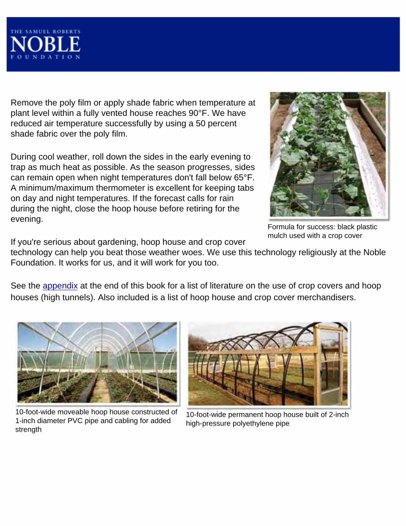
Formula for success: black plastic mulch used with a crop cover
Remove the poly film or apply shade fabric when temperature at plant level within a fully vented house reaches 90°F. We have reduced air temperature successfully by using a 50 percent shade fabric over the poly film.
During cool weather, roll down the sides in the early evening to trap as much heat as possible. As the season progresses, sides can remain open when night temperatures don't fall below 65°F. A minimum/maximum thermometer is excellent for keeping tabs on day and night temperatures. If the forecast calls for rain during the night, close the hoop house before retiring for the evening.
If you're serious about gardening, hoop house and crop cover technology can help you beat those weather woes. We use this technology religiously at the Noble Foundation. It works for us, and it will work for you too.
See the appendix at the end of this book for a list of literature on the use of crop covers and hoop houses (high tunnels). Also included is a list of hoop house and crop cover merchandisers.
10-foot-wide moveable hoop house constructed of 1-inch diameter PVC pipe and cabling for added strength
10-foot-wide permanent hoop house built of 2-inch high-pressure polyethylene pipe

10-foot-wide moveable hoop house equipped with removable end walls and roll-up door
Roll-up side walls, fully retracted
Using shade cloth for temperature reduction

Building Materials Needed to Construct One Mini Tunnel to Cover a 40-Inch by 30-Foot Recycled Auto Tire or Corrugated Sheet Metal Raised Bed
Quantity Item Description Unit Price Total200 feet ¼-inch nylon rope $0.08/ft $16.001,8-ft by 38-ft sheet 6-mil greenhouse poly film $0.13/sq ft $39.5280 foot ½-inch sch 40 PVC pipe $0.22/ft $17.6020 foot 1-inch sch 40 PVC pipe $0.44/ft $8.8044 2-inch wood screw $0.05 $2.202 3/8-inch by 2-foot rebar $0.75 $1.502 Eye screw $0.50 $1.00*Prices may vary depending on location, etc. Total $86.62
After years of tinkering with existing low tunnel designs and making various modifications, we've developed a low tunnel custom designed for use with both recycled auto tire and corrugated sheet metal beds. The low tunnel will provide the gardener with a versatile, user-friendly means of protecting and enhancing the growth of crops growing in permanent raised beds.
The basic components of this low tunnel are hoops made from PVC pipe, a polyethylene greenhouse film cover and hold-down straps made from 1/4-inch rope. The tunnel cover is held in place using rope straps located between each hoop. The straps enable the user to raise and lower the cover without unfastening or fastening the cover every time the tunnel is opened or closed.
Begin tunnel construction by fabricating hoop receptacles from 1-inch schedule 40 PVC pipe. When attached to the side of beds, the receptacles hold the hoops in an upright position.

If you intend to cover an auto tire bed, cut the pipe into 6-inch pieces. You will need to prepare 22 pieces to construct a 30-foot-long tunnel. Drill a 7/16-inch-diameter hole completely through the side of each piece of pipe 2 inches from one end. Attach the receptacles to the bed sides using 2-inch wood screws. Locate one screw in the middle of the pipe and the other 1 inch above the base of the pipe. The use of two screws will keep the pipe from rotating. When attached, the top of the pipe should be no higher than the side of the bed, and the drilled holes should run parallel to the side of the bed. Space the hoop receptacles 3 feet apart starting at the end of the bed.
If you are covering a corrugated sheet metal bed, cut the 1-inch PVC pipe into 4-inch pieces. You will need to prepare 22 pieces to construct a 30-foot-long tunnel. Attach the pipe to the 2-inch by 4-inch wood frame using 2-inch wood screws. Locate one screw in the center of the pipe and locate the other 1 inch from the base of the pipe. When attached, the pipe should be level with the top of the frame. Space the
hoop receptacles 3 feet apart starting at the end of the bed.
Fabricate hoops for the tunnel out of 1/2-inch schedule 40 PVC pipe. We recommend cutting a 20-foot joint of pipe into three equal sections measuring 80 inches. An 80-inch hoop will create a tunnel about 2 1/2 feet high when used in conjunction with a 40-inch-wide bed. You will need to prepare 11 hoops for use with a 30-foot-long bed.
We recommend using 6-mil greenhouse film for the tunnel cover. Thinner film will work, but isn't as durable and will need to be replaced more often. Construction grade plastic film may be used, but will need to be replaced annually due to sunlight degradation. Porous floating row covers may be used, but only the heavier weight covers will provide any long-term serviceability due to the wear and tear on the fabric that occurs with repeated opening and closing of the tunnel.
The tunnel cover will need to be wide enough and long enough to hang over the sides and the ends of the tunnel. When using 80-inch-long hoops on a 30-foot-long bed, you will need to prepare a piece of film 8 feet wide and 38 feet long.

Proceed with the tunnel assembly by installing the hoops. Insert one end of the hoop into a receptacle and the other end of the hoop into the receptacle directly opposite on the other side of the bed. When installed correctly, the hoop ends should rest against the screws used to secure the receptacles to the sides of the beds.
To prevent excess bending of the end hoops when the cover is applied, use a piece of rope to connect the top of the hoops to the ends of the beds. If you're covering a rubber lumber bed, fasten the rope to an eye screw inserted into the rubber at each end of the bed. If you're covering a corrugated sheet metal bed, tie the rope to the sucker rod stakes at each end of the bed.
Eye screw inserted into bed wall at end of bed
Use a piece of rope to connect the top of the hoops to the ends of the beds.

Centering the tunnel cover
Preparing cover end prior to securing to frame
Securing cover end to frame
Next, install the tunnel cover. Do this on a calm day to make the job easier. Make sure the cover is centered over the hoops. Gather the cover at one end of the tunnel and twist it into a tight spiral. If you're covering a corrugated sheet metal bed, tie off the twisted end of the cover with a piece of rope and secure it to the middle two sucker rod stakes at the end of the bed using the rope. Repeat the process on the other end of the tunnel, pulling the cover towards you prior to securing to the stakes. Stretching the cover removes excess slack in the material.
With one exception, the process is the same if you're installing a tunnel on a rubber lumber bed. We use a 1-foot-long U-shaped stake made from a 3/8-inch-diameter piece of rebar to secure the tied off ends to the soil at both ends of the bed.
Next, make the hold-down straps. Select 1/4-inch-diameter rope to use for the straps. To reduce the amount of abrasion that occurs when the cover is raised and lowered, choose a rope that is soft to the touch. We'vehad good results using nylon braided rope. Two hundred feet of rope is more than enough to make the hold-down straps for a 30-foot-long tunnel, reinforce the end hoops and tie off both ends of the cover. Prepare the straps by cutting the rope into 16-foot pieces. You will need one strap for each hoop.
U-shaped stake

Proper orientation of hold down rope strap at point of attachment to bed
Exploded view of knot
If you're covering a corrugated metal bed, start at one end of the bed and thread a piece of rope half-way through the opening between the sucker rod stake and the bed wall directly beneath a hoop receptacle. Throw both free ends over the cover to the other side in the direction of the opposite receptacle. One half of the rope should be positioned on one side of the hoop and the other half on the other side of the hoop.
Tie a loop in one end of the rope and thread the other end behind the sucker rod stake beneath the receptacle and through the loop. Pull down on the free end to cinch up the hold-down strap. Tie off the free end using a slippery half hitch knot. Repeat the process when installing remaining straps.
Slippery half hitch knot
Loop tied in one end of rope

Proper orientation of hold down strap on end hoop
Adjust hold down strap to draw down cover several inches below hoop
A restraining strap may or may not be needed for each end hoop, depending on the amount of tension desired. If you install a hold-down strap on the end hoops, an 8-foot piece of rope will suffice. Position the strap on the side of the hoop towards the center of the bed.
If you're covering a rubber lumber bed, the process of installing the hold-down straps is similar, with one exception. The rope should be threaded through the hole drilled in each receptacle.
Cinching up the straps forces the cover against the hoop. Adjust the tension so the cover can slide up and down on the hoops with some resistance. The cover should be drawn down several inches below the hoops. Adjust the strap too tight and you won't be able to raise or lower the cover; too loose and the cover will flop in the wind. The hold-down straps will have a tendency to loosen over time. If you need to cinch up a strap, release the knot, adjust the tension and retie the knot.
During the spring and fall, it is often necessary to ventilate tunnels on sunny days and close them when cold or rainy weather threatens. Because of the tension exerted by the hold-down straps, the cover will tend to remain in any desired position. Over time, however, the cover will slide down the hoops. One method of ensuring the tunnel remains fully ventilated is to tie the cover together with rope or with a bungee cord when the cover is bunched together at the top of the tunnel.
Venting a mini tunnel
Tie the cover together with rope or with a bungee cord.

A more flexible method of ventilating the tunnel employs the use of pins inserted into holes drilled into the hoops at desired locations. The pins prevent the cover from sliding down the hoops. This technique enables the gardener to regulate the amount of ventilation on both sides of the tunnel independently of one another.
When the tunnel is no longer needed, the cover can be nested to one side of the bed. Depending on the crops grown, the hoops and straps can remain in place or be removed from the bed. Leaving the tunnel components on site year round is less work, but there is a downside – both the polyethylene cover and PVC pipe are susceptible to sunlight degradation, which will shorten their service life.

Custom-made wood tomato cages
To realize the maximum potential of your raised bed garden, grow vertically. Using the space above your beds will make your garden more productive. In addition toincreasing yield, the practice helps fruit develop off the ground, keeping them cleaner and less susceptible to rot. Elevated crop canopies dry quicker, reducing the risk of foliage disease. Spraying, pruning and harvesting are easier when crops are grown vertically.
There are many support systems gardeners use to grow plants vertically. The one used most extensively at the Noble Foundation consists of cages constructed of 6-inch by 6-inch concrete reinforcing mesh and used to support crops such as tomato, pepper, eggplant, pea, bean and cucumber.
A 5-foot by 150-foot roll of re-mesh costs about $60 and will make 37 cages 4 1/2 feet tall (height above soil level) by 15 inches in diameter or 74 cages 2 feet tall by 15 inches in diameter. If you need only a few cages, check out local construction sites. Chances are you can find enough scrap pieces to suit your needs.
Plan on using the taller cages when growing pole bean, pea, cucumber and indeterminate tomato. The shorter cages work for eggplant, pepper, dwarf pea and determinate tomato.
Custom made pea and bean cage
Removing a 48-inch section of mesh from roll

A roll of concrete reinforcing mesh
Using a bolt to bend wire "fingers"
Mesh wire with bent fingers
Connecting fingers to opposite edge to form cage
Removing an end rung of wire to form wire "toes" Re-mesh cages and cucumbers - what a combo!

Pepper plants supported by a stake and weave trellis
Another popular trellising method known as the 'stake and weave' or 'Florida Weave' uses layers of twine attached to metal or wood stakes to provide plant support. Typically stakes are driven into the ground about 1 foot and spaced between every other plant. A larger (stronger) stake should be located at each end of a bed. After plants reach 1 foot in height, nylon twine is tied to the first stake at the end of the bed then looped around each stake down the row. Throughout the process, it is important to keep the twine taut to prevent sagging. At the end of the row, the twine is looped around the end stake and passed along the other side of the plants, again looping each stake until it is finally tied to the end stake at the
beginning of the row where the process started. The first string is placed at approximately 10 inches above the ground and another string is added as the plants grow each additional 10 inches. The stake and weave method is ideally suited for tomato, pepper and eggplant.

Tomato plants killed by soil-borne disease organisms
Use a water breaker to uniformly wet bed surfaces
Soil-borne pests tend to accumulate in intensively managed gardens. Traditionally, pesticides applied before planting have been used to control a variety of insect pests, weeds and nematodes. Although the treatments are effective, most people object to them because of their toxicity to animals and humans. Also, many soil-applied pesticides are restricted to use on certain vegetable crops.
If you are looking for a non-chemical method of soil-borne pest control, consider solarization, achieved by placing clear plastic film on moist soil during the summer. Plants often grow faster in solarized soil and produce higher yields, both of which are attributable to improved pest control and increased nutrient release from organic matter decomposition.
The plastic film allows the sun's radiant energy to be trapped in the soil. Soil temperature at a 2-inch depth can rise to 130°F, hot enough to kill many disease-causing organisms, nematodes, insects and weed seeds. Although soil solarization controls many weed species, it will not affect deeply rooted perennial weeds such as bermudagrass, johnsongrass and nutsedge (nutgrass). Use a herbicide before solarization to control perennial weeds.
Plant-available nutrient levels increase due to accelerated organic matter decomposition that occurs during solarization. Consequently, you will want to wait until after solarization to soil test. You may not need to apply fertilizer prior to planting your next crop. Also, pay close attention to soil salinity. Soluble salt levels increase with solarization. Consider leaching beds with water if reported soluble salt levels exceed 1000 ppm. Before laying plastic film, prepare beds following the procedure outlined in the 'Seed Bed Preparation' section. Solarization is most effective if the seedbed is smooth and the plastic film rests snug against the soil.

Six-foot-wide clear film applied to single beds
Wet soil conducts heat better than dry soil, making soil organisms more vulnerable. Before laying plastic film, thoroughly soak the beds by using the drip system in combination with a surface watering. Most beds will not need to be irrigated again during solarization. However, if the soil is sandy or if the beds have a high profile, it may be necessary to re-irrigate using the drip system.
Plastic solarization film can be applied to beds separately or in combination. When applied to single beds, the film is laid like mulch film. See Plastic Mulch Application section for details. In complete coverage, film is laid down to form a continuous surface over a few beds or the entire garden, depending on the size of the sheet. The edges of the film should be held in place by burying them in the soil.
For small gardens, UV-inhibiting clear plastic film, sometimes called drop cloths, can be purchased from hardware or home improvement stores. The plastic film can be cut to size or spliced with clear patching tape. The
heavier, thicker film is more tear- and puncture-resistant and can be reused.
For market gardens, clear film can be purchased in rolls 6 feet wide by 2,000 feet long or longer. The 6-foot width is ideal for 40-inch-wide beds. For a list of companies that carry large rolls of clear film, see the appendix.
In southern states, film should be left in place for four to six weeks to allow the soil to heat to the greatest depth possible, while in cooler climates, film should remain in place all summer. Results are best with high solar radiation and minimal wind, regardless of geographical location.

Large sheet of film covering multiple beds
Higher soil temperatures and deeper heating may be achieved with a double layer of plastic. The top layer of film can be applied loosely to form an air pocket capable of reducing heat loss from the soil. Even higher soil temperatures can be obtained when beds are solarized within a closed greenhouse or hoop house. At the Noble Foundation, hoop house bed temperatures at a depth of 6 inches commonly reach 120°F during August.
Once plastic has been removed, the cooled, treated soil can be used. Plastic may remain in place through the winter; however, it may start to degrade, making cleanup difficult in the spring.
There is no reason to cultivate the soil before planting if the beds have been prepared properly. If required, fertilizer may be incorporated prior to planting. Try not to incorporate fertilizer deeper than 3 inches, or you risk bringing weed seeds and pathogens to the surface.
Because soil solarization is laborious and will reduce production for a portion of the summer, limit its use by employing other pest control strategies instead, such as cover crops, organic amendments and crop rotation.
Plastic Mesh Fencing Merchandisers
Hummert (800) 325-3055 www.hummert.com
Gempler's (800) 382-8473 www.gemplers.com
Ben Meadows Company (800) 241-6401 www.benmeadows.com
Farmtek (800) 327-6835 www.farmtek.com
Drip Irrigation Merchandisers
Trickl-eez (800) 874-2553 www.trickl-eez.com
Irrigation-Mart (800) 729-7246 www.irrigation-mart.com
Barry Hill Irrigation (800) 345-3747 www.berryhilldrip.com
Drip Works (800) 522-3747 www.dripworks.com
Plastic Mulch Merchandisers
American Plant Products (800) 522-3376 www.americanplant.com
Trickl-eez (800) 874-2553 www.trickl-eez.com
Irrigation-Mart (800) 729-7246 www.irrigation-mart.com
Johnny's Seeds (877) 564-6697 www.johnnyseeds.com
Peaceful Valley Farm Supply (888) 784-1722 www.groworganic.com
Glaser Seeder Merchandisers
Johnny's Seeds (877) 564-6697 www.johnnyseeds.com
Peaceful Valley Farm Supply (888) 784-1722 www.groworganic.com
Irrometer Merchandisers
Barry Hill Irrigation (800) 345-3747 www.berryhilldrip.com

Gempler's (800) 382-8473 www.gemplers.com
Trickl-eez (800) 874-2553 www.trickl-eez.com
Irrigation-Mart (800) 729-7246 www.irrigation-mart.com
Irrometer Merchandisers
Barry Hill Irrigation (800) 345-3747 www.berryhilldrip.com
Grow Pro and Add-It Fertilizer Injector Merchandisers
Peaceful Valley Farm Supply (888) 784-1722 www.groworganic.com
Strong Enterprises (916) 797-1056 www.fertilizerdispensers.com
Drip Works (800) 522-3747 www.dripworks.com
EZ-FLO Fertilizer Injector Merchandisers
Irrigation-Mart (800) 729-7246 www.irrigation-mart.com
A.M. Leonard (800) 543-8955 www.amleo.com
Hummert (800) 325-3055 www.hummert.com
Drip Works (800) 522-3747 www.dripworks.com
Peaceful Valley Farm Supply (888) 784-1722 www.groworganic.com
Soil Probe Merchandisers
Peaceful Valley Farm Supply (888) 784-1722 www.groworganic.com
A.M. Leonard (800) 543-8955 www.amleo.com
Gempler's (800) 382-8473 www.gemplers.com

Hoop House and Crop Cover Merchandisers
American Plant Products (800) 522-3376 www.americanplant.com
Morgan County Seed (573) 378-2655 www.morgancountyseeds.com
Hoop House Structures (800) 760-5192 www.hoophouse.com
Hummert (800) 325-3055 www.hummert.com
A.M. Leonard (800) 543-8955 www.amleo.com
Peaceful Valley Farm Supply (888) 784-1722 www.groworganic.com
www.groworganic.com
< Previous:
< Previous:
Solarizing Film Merchandisers
Trickl-eez (800) 874-2553 www.trickl-eez.com
Hummert (800) 325-3055 www.hummert.com
Irrigation-Mart (800) 729-7246 www.irrigation-mart.com

Raised Bed Gardening References
Ball, Jeff. Jeff Ball's 60-Minute Vegetable Garden. New York, NY: Macmillan Publishing, 1992.
Bartholomew, Mel. Square Foot Gardening. Emmons, PA: Rodale Press, 1981.
Doscher, Paul; Timothy Fisher and Kathleen Kalb. Intensive Gardening 'Round the Year. Brattleboro, VT: Stephen Greene Press, 1981.
Hunt, Marjorie and Brenda Bartz. High Yield Gardening. Emmons, PA: Rodale Press, 1986.
Jeavons, John. How to Grow More Vegetables than You Ever Thought Possible on Less Land than You can Imagine. Berkeley, CA: Ten Speed Press, 1995.
Mittleider, Jacob. More Food from Your Garden. Santa Barbara, CA: Woodbridge Press, 1975.
The Editorial Staff of Ortho Books. Weather-Wise Gardening, South Edition. San Francisco, CA: Ortho Books, 1974.

Hoop House and Season Extension References
www.hightunnels.org Your one-stop-shop for all things pertaining to high tunnel (hoop house) growing.
Four Season Harvest: Organic Vegetables from Your Home Garden All Year Long. Eliot Coleman 1999, 212 pages Chelsea Green Publishing www.chelseagreen.com
The Hoophouse Handbook Lynn Byczynski 2003, 60 pages Fairplain Publishing, Inc. www.growingformarket.com
The New Organic Grower: A Master's Manual of Tools and Techniques for the Home and Market Gardener. Eliot Coleman 1995, 340 pages Chelsea Green Publishing www.chelseagreen.com
Season Extension Techniques for Market Gardeners Janet Bachman and Richard Earles 2000, 24 pages ATTRA www.attra.org
Solar Gardening: Growing Vegetables Year-Round the American Intensive Way Leandre and Gretchen Poisson 1994, 267 pages Chelsea Green Publishing www.chelseagreen.com
The Winter-Harvest Manual Farming the Backside of the Calendar Eliot Coleman 2001, 62 pages www.fourseasonfarm.com When you have a garden, you have a future. And when you have a future, you are alive. – Frances Hodgson Burnett

Expanded Graphics Section
Permanent Raised Bed Gardening

Scale drawing of the Martin Luther King, Jr. Outreach Center’s Bootstrap Community Garden in Ardmore, OK.
Site Selection
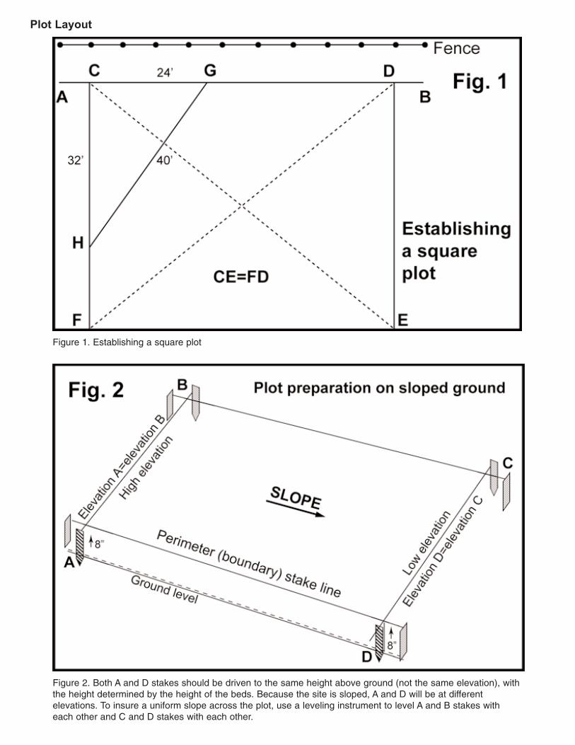
Figure 1. Establishing a square plot
Figure 2. Both A and D stakes should be driven to the same height above ground (not the same elevation), withthe height determined by the height of the beds. Because the site is sloped, A and D will be at different elevations. To insure a uniform slope across the plot, use a leveling instrument to level A and B stakes witheach other and C and D stakes with each other.
Plot Layout

Corrugated Sheet Metal Beds: Material Preparation
Corrugated Sheet Metal Beds: Bed Assembly

Corrugated Sheet Metal Beds: Bed Assembly (cont.)

Corrugated Sheet Metal Beds: Bed Assembly (cont.)

Corrugated Sheet Metal Beds: Bed Assembly (cont.)

Corrugated Sheet Metal Beds: Bed Assembly (cont.)

Corrugated Sheet Metal Beds: Bed Assembly (cont.)

Installing a Drip Irrigation System

Installing a Drip Irrigation System (cont.)
Top: Emitter Line Placement (1-3 crop rows per bed) Bottom: Emitter Line Placement (4-8 crop rows per bed)

Plastic Mulch Application
Planting Techniques for Raised Bed Gardens
A set of template row markers with stakes attached

Planting Techniques for Raised Bed Gardens (cont.)
Dimensions of the Noble Foundation rolling row marker
Top: Cotter pin used to secure threaded rod to axlebodyMiddle: Close up of rolling markerBottom: Mounting additional marking wheels ontoaxle
Crosschecking rows with a rolling marker equipped with crosswires

Planting Techniques for Raised Bed Gardens (cont.)
An opened eye screw is used to lock the cross wire into place.
Cross member of a plant locator calibrated for 12-, 18- and 24-inch spacings

Planting Techniques for Raised Bed Gardens (cont.)
Drip irrigation with its high frequency/low volume watering keeps a much more ideal soil moisture levelthan does a sprinkler.
Water Management

Water Management (cont.)
A tensiometer

Feeding the Growing Garden

Selection and Use of Fertilizer Injectors

Selection and Use of Fertilizer Injectors (cont.)

Construction Plans for a Custom Designed Low (Mini) Tunnel

Construction Plans for a Custom Designed Low (Mini) Tunnel (cont.)