sthira: a formal approach to minimize voltage …iacoma.cs.uiuc.edu/iacoma-papers/pact17.pdf · of...
TRANSCRIPT

Sthira: A Formal Approach to Minimize Voltage Guardbandsunder Variation in Networks-on-Chip for Energy Efficiency
Raghavendra Pradyumna Pothukuchi, Amin Ansari,∗ Bhargava Gopireddy, and Josep TorrellasUniversity of Illinois at Urbana-Champaign ∗Qualcomm Research
http://iacoma.cs.uiuc.edu
Abstract—Networks-on-Chip (NoCs) in chip multiprocessorsare prone to within-die process variation as they span thewhole chip. To tolerate variation, their voltages (Vdd) carryover-provisioned guardbands. As a result, prior work hasproposed to save energy by operating at reduced Vdd whileoccasionally suffering and fixing errors. Unfortunately, theseproposals use heuristic controller designs that provide no errorbounds guarantees.
In this work, we develop a scheme that dynamically mini-mizes the Vdd of groups of routers in a variation-prone NoCusing formal control-theoretic methods. The scheme, calledSthira, saves substantial energy while guaranteeing the stabilityand convergence of error rates. We also enhance the schemewith a low-cost secondary network that retransmits erroneouspackets for higher energy efficiency. The enhanced scheme iscalled Sthira+. We evaluate Sthira and Sthira+ with simulationsof NoCs with 64–100 routers. In an NoC with 8 routers per Vdd
domain, our schemes reduce the average energy consumptionof the NoC by 27%; in a futuristic NoC with one router perVdd domain, Sthira+ and Sthira reduce the average energyconsumption by 36% and 32%, respectively. The performanceimpact is negligible. These are significant savings over the state-of-the-art. We conclude that formal control is essential, and thatthe cheaper Sthira is more cost-effective than Sthira+.
Keywords-Network on chip; Variation; Control theory.
I. INTRODUCTION
Variations in process, supply voltage (Vdd), and tempera-ture parameters present an increasingly important challengeto achieve energy efficiency in processors. These variationsarise from the reduced voltage and feature dimensionsin upcoming processors [1]. To build resilient processorsthat can tolerate such variations, designers are forced touse conservative guardbands, defeating the goal of energyefficiency.
Networks on Chip (NoCs) are especially prone to suchvariations. They connect distant parts of the chip which,due to variations, exhibit different characteristics. Hence, theNoC has to be designed to safely work in the slowest andin the leakiest parts of the chip. This leads to conservativedesigns and energy inefficiencies. Unfortunately, the NoCconsumes a substantial fraction of the on-chip energy —potentially up to ≈30%, according to the literature [2], [3],[4], [5], [6], [7] — and this contribution may increase incommunication-dominated future exascale systems [8]. Asa result, we need to find novel NoC solutions that balancethe opposing goals of low energy and variation tolerance.
A possible approach to achieve energy efficiency in avariation-affected environment is to operate the design withreduced guardbands, occasionally suffering and fixing errors.Prior proposals such as Razor [9] and BlueShift [10] haveused circuit techniques to run cores at high clock frequenciesfor the available timing guardbands. Tangle [11] has reducedthe Vdd guardbands of routers in an NoC without chang-ing their frequency. Bacha and Teodorescu have reduced
the Vdd guardbands in processors while monitoring ECCfeedback [12], [13].
Nearly all of these proposals, however, use ad hoc de-cisions, relying heavily on empirically-tuned settings tocontrol the frequency or the Vdd that leads to improvedoperation. Such heuristic algorithms are often too conserva-tive, and sacrifice energy efficiency. Alternatively, they aresometimes highly complex, which makes their design, tuningand verification efforts prohibitively high. Moreover, thesettings of the ad hoc schemes are known to work only forthe specific environments that are used to design them, andwe do not know how well they work under other conditionsnot encountered at design time. Lastly, ad hoc schemes donot have a clear design methodology. This means that re-using the design for future architectures requires a full searchof a large design space because the current design is highlytuned to the current architecture.
To address these limitations, we require formal method-ologies. In this paper, we use formal control techniquesto design a Vdd controller. Our goal is to dynamicallycontrol the Vdd of groups of routers in a variation-proneNoC, keeping Vdd as low as possible while sustaining asmall but tolerable number of errors. The design, calledSthira, provides guarantees on the convergence, stability, andmaximum resulting error rates for the NoC under control.The result is a robust, scalable and energy-efficient system.
We propose two Sthira designs: a basic version and anaggressive variant called Sthira+. The latter additionallyincludes a low-cost secondary network that operates atnominal Vdd and retransmits a packet when it has suffered anerror in the primary NoC. Retransmitting the packet on theprimary NoC could result in repeated errors, which wouldthen force the controller to increase the steady-state Vdd
suboptimally.We evaluate Sthira+ and Sthira with simulations of
variation-affected NoCs with 64–100 routers running a mixof workloads. With 8 routers per Vdd domain, our schemesreduce the average energy consumption of the NoC by27% with negligible performance overhead. For a futuristicdesign with one router per Vdd domain, Sthira+ and Sthirareduce the average energy consumption of the NoC by36% and 32%, respectively, with negligible performanceimpact. These savings are obtained after taking into accountthe penalty of power losses in voltage regulators, and aresubstantially higher than those attained by prior approaches.While the secondary network helps Sthira+ attain higherenergy savings, its non-negligible hardware cost makesSthira+ less cost-effective than Sthira.
Overall, the contributions of this work are:
• The design of Sthira, a scheme that dynamically min-imizes the Vdd of groups of routers in an NoC usingformal control-theory approaches.

• Sthira’s enhancement into Sthira+, a scheme that furtherintegrates a low-cost secondary network operating atnominal Vdd for higher energy efficiency.
• An evaluation of Sthira and Sthira+ that demonstrateslarge and controllable energy reductions with negligibleperformance impact over the best existing approaches.
II. BACKGROUND
A. Process Variations and Energy Savings
With decreasing feature sizes, process variations havebecome an important concern for chip manufacturers [1].In this paper, we focus on Within-Die (WID) processvariations. WID variations have a systematic and a randomcomponent [14], [15]. The random component is due to ran-dom dopant fluctuations, while the systematic component istypically due to imprecisions in the manufacturing process,and exhibits significant spatial correlation. WID variationsmay reduce the delay in some paths and increase it in others.This results in higher Vdd guardbands and lower operatingfrequencies at the chip level, as dictated by the slowest paths.
Aggressively reducing Vdd or frequency guardbands de-creases energy consumption but can create timing violations,as some of the variation-affected paths may be too slow.If such violations can be detected and corrected withoutsignificant overheads, overall energy efficiency can improve.This insight has been used by several researchers to developheuristics at the circuit level [9], [10], [16] or at the architec-tural level [11], [12], [13], [17] to reduce energy consump-tion in a variation-affected chip. Specifically, Razor [9] andBlueShift [10] decrease the frequency guardbands in proces-sor pipelines. Tangle [11] and Bacha and Teodorescu [12],[13] reduce Vdd guardbands in NoCs and processors whilekeeping the frequency unchanged. Hi-ECC [17] saves energyby reducing DRAM refresh frequency at the expense ofincreasing the strength of ECC codes. Unlike these works,we propose a control-theoretic scheme to reduce the Vdd
of the NoC routers (without changing their frequency).Additionally, we observe that we can obtain large energysavings by tolerating a small but non-zero sustained errorrate, instead of completely avoiding the errors. Therefore,our design lowers the Vdd of the routers to sustain a constanterror rate.
B. Modeling Timing Faults
As Vdd decreases, certain paths may start missing timingunder certain logic values and cause intermittent faults.This timing fault rate increases as Vdd decreases. VARIUS-NTV [15] is a tool that models process variations andthe timing violations that ensue from reduced guardbands.VARIUS-NTV takes a certain logic structure (e.g., thesynthesized RTL implementation of an NoC router), andgives the probability of a timing error for each path inthe different pipeline stages, for a given Vdd. In this paper,we conservatively assume that whenever a timing violationoccurs, it causes an incorrect execution.
C. Supporting Multiple Vdd Domains
An effective approach to tolerate process variations is todivide a logic component into multiple Vdd domains. In thisway, a high Vdd can be applied to sections of the componentthat are slow due to systematic variations, and a low Vdd to
sections that are fast. In an NoC, a natural Vdd domain is aset of neighboring routers.
Currently, using multiple on- or off-chip Switching Volt-age Regulators (SVR) to provide multiple Vdd domains con-sumes significant area and power [18]. However, upcomingtechnology will provide better solutions. One approach mayinvolve integrating Vdd regulators hierarchically [19], [20].The first level of the hierarchy consists of a few SVRs on astacked die or on the package, while the second level consistof many on-chip low-drop-out (LDO) regulators. Each LDOis fed by one of the SVRs and provides the Vdd for a domain.The area overhead of LDOs is negligible, as they reuse thehardware for a power-gating circuit. In addition, LDOs havehigh efficiencies if the ratio of their output (VO) to input(VI ) voltage is close to 1. Also, level converters, requiredfor communication across Vdd domains, can be efficientlydesigned by combining them with latches [21]. In this paper,we use 8 routers per Vdd domain for a conservative design,and 1 router per Vdd domain for an aggressive, futuristicdesign. The IBM POWER8 processor chip has demonstrateda hierarchical, LDO-based Vdd regulator system that attainsa peak power efficiency of 90.5% [22]. Therefore, to keepour analysis simple, in this paper we assume that a near-future system that provides multiple Vdd domains in the NoCwastes 10% of the total power to voltage regulation.
III. NECESSITY OF FORMAL CONTROL
The general approach of designing controllers usingheuristics has a few drawbacks. First, the effort to designand tune the controller is high, due to the lack of aconsistent methodology. In addition, much of this effort hasto be repeated when designing a slightly-different controller.What’s worse, even after painstaking efforts, hand-tunedheuristic-based algorithms may incur unpredictable and un-acceptable behavior outside the training set [23]. As a result,heuristic schemes are typically kept simple to avoid suchunpredictable behavior. With a few exceptions, this makesthe algorithms conservative and reduces their capability toadjust their actions to the dynamic execution.
The alternative is to use control-theoretic techniques [24].Such techniques are formally derived, and manage thesystem in an organized manner. They gracefully adapt tochanges, and provide guarantees on: (i) convergence, (ii)stability, and (iii) error bounds [23]. Convergence meansthat the system will eventually reach the desired operatingpoint specified by the designer — if such an operating pointexists. Stability means that once the steady state is attained,the system will not deviate from it. Error bounds guaranteeslimit the maximum error that the system can have once thesystem reaches the steady state. They also limit the peakovershoot and undershoot while in the process of reachingthe steady state. Overall, control-theoretic systems can de-liver aggressive benefits without unpredictable behavior.
As an example of the need for formal control, considerthe heuristic scheme used in Tangle [11] to reduce energy inthe context of process variations. A controller periodicallyreduces the Vdd of the routers in an NoC and, if an erroroccurs in a flit, immediately raises the Vdd of all routersin the path of that flit. This approach saves some energyin the NoC, but is conservative in its decision-making andsub-optimal.
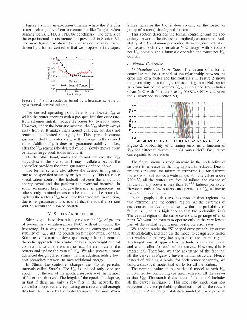
Figure 1 shows an execution timeline where the Vdd of arouter is changed by a heuristic controller like Tangle’s whenrunning GemsFDTD, a SPEC06 benchmark. The details ofthe experimental infrastructure are presented in Section VI.The same figure also shows the changes on the same routerdriven by a formal controller that we propose in this paper.
0 50 100 150
Epochs (50 µs)
0.45
0.50
0.55
0.60
0.65
0.70
0.75
0.80
Rou
ter
Vd
d
Heuristic
Formal Control
Figure 1: Vdd of a router as tuned by a heuristic scheme orby a formal-control scheme.
The desired operating point here is the lowest Vdd atwhich the router operates with a pre-specified tiny error rate.Both schemes initially reduce the router Vdd to a low value.However, under the heuristic scheme, the Vdd slowly swaysaway from it. It makes many abrupt changes, but does notreturn to the desired setting again. This approach cannotguarantee that the router’s Vdd will converge to the desiredvalue. Additionally, it does not guarantee stability — i.e.,after the Vdd reaches the desired value, it slowly moves awayor makes large oscillations around it.
On the other hand, under the formal scheme, the Vdd
stays close to the low value. It may oscillate a bit, but thecontroller provides the three guarantees defined above.
The formal scheme also allows the desired timing errorrate to be specified statically or dynamically. This referencespecification controls the tradeoff between the amount ofenergy saved and the performance overhead incurred. Insome scenarios, high energy-efficiency is paramount; inothers, only minimal errors can be tolerated. The controllerupdates the router’s Vdd to achieve this error rate. In addition,due to its guarantees, it is assured that the actual error ratewill be within the allowed bounds.
IV. STHIRA ARCHITECTURE
Sthira’s goal is to dynamically reduce the Vdd of groupsof routers in a variation-prone NoC (without changing thefrequency) in a way that guarantees the convergence andstability of Vdd, and the bounds on flit error rates. For this,Sthira uses a controller developed using a formal, control-theoretic approach. The controller uses light-weight controlconnections to all the routers to read the error rate in therouters and update the routers’ Vdd. We also present a moreadvanced design called Sthira+ that, in addition, adds a low-cost secondary network to save additional energy.
In Sthira, the controller changes the Vdd at periodicintervals called Epochs. The Vdd is updated only once perepoch — at the end of the epoch, irrespective of the numberof flit errors observed. The length of the epochs is adaptive,in that if there are only a few flits in the network, thecontroller postpones any Vdd tuning on a router until enoughflits have been seen by the router to make a decision. When
Sthira increases the Vdd, it does so only on the router (orgroup of routers) that logged the error.
This section describes the formal controller and the sec-ondary network. The discussion implicitly assumes the avail-ability of a Vdd domain per router. However, our evaluationwill assess both a conservative NoC design with 8 routersper Vdd domain, and a futuristic one with one router per Vdd
domain.
A. Formal Controller
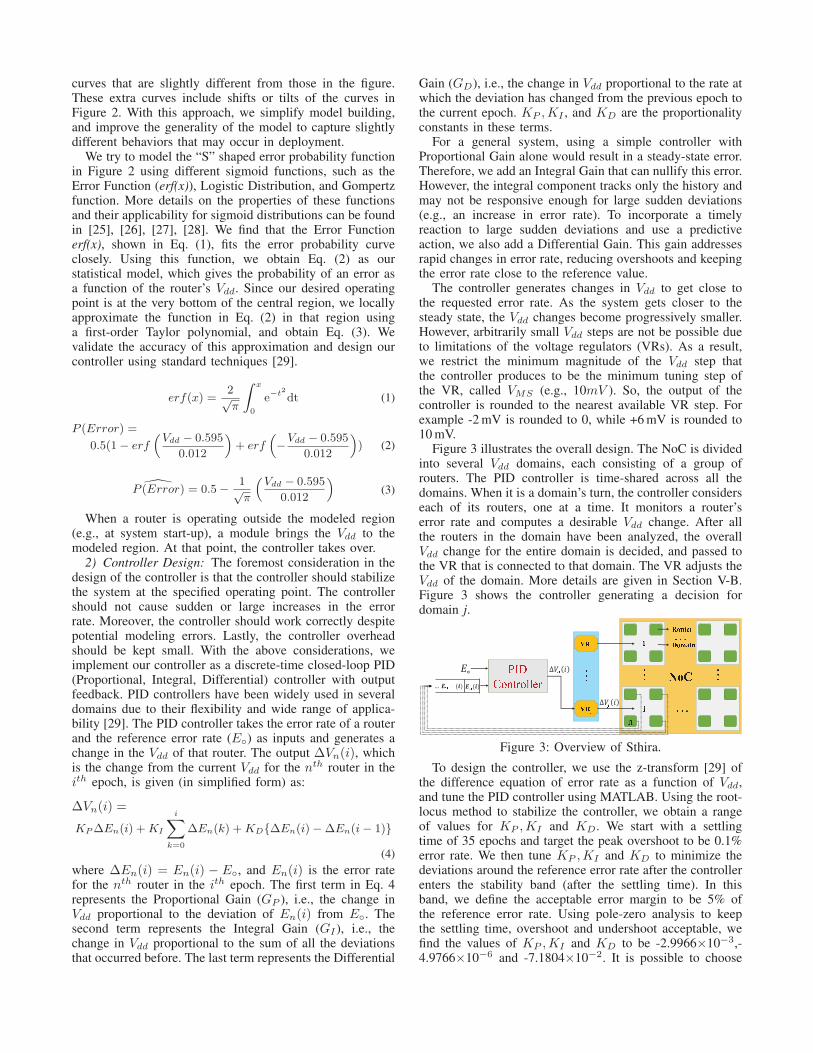
1) Modeling the Error Rate: The design of a formalcontroller requires a model of the relationship between theerror rate of a router and the router’s Vdd. Figure 2 showsthe probability of a timing error occurring in an NoC routeras a function of the router’s Vdd, as obtained from studiesof an NoC with 64 routers using VARIUS-NTV and othertools (described in Section VI).
� � � �� � � �� � � �� � � �� � �� � �� � � �� � � � � � � � � � � � � � � � � � � � � � � � � � � � � � � � � � � � � � � � �� ��� ����� � �� ! ����
Figure 2: Probability of a timing error as a function ofVdd for different routers in a 64-router NoC. Each curvecorresponds to one router.
The figure shows a steep increase in the probability ofan error in a router as the Vdd applied is reduced. Due toprocess variations, the minimum error-free Vdd for differentrouters is spread across a wide range. For Vdd values above720mV , all the routers are free of failure; the chance offailure for any router is less than 10−18 failures per cycle.However, only a few routers can operate at a Vdd as low as570mV without failure.
In this graph, each curve has three distinct regions: thetwo extremes and the central region. At the extremes ofeach curve, the Vdd is either so low that the probability offailure is 1, or it is high enough that the probability is 0.The central region of the curve covers a large range of errorrates. We want the routers to operate only in the very lowestpart of the central region, near negligible error rates.
We need to model the “S” shaped error probability curvesmathematically, and then use the model to design a controllerthat works for the very low segment of the central region.A straightforward approach is to build a separate modeland a controller for each of the curves. However, this isimpractical. Therefore, we take advantage of the fact thatall the curves in Figure 2 have a similar structure. Hence,instead of building a model for each router separately, webuild a statistical model that works for all the routers.
The nominal value of this statistical model at each Vdd
is obtained by computing the mean value of all the curvesat that Vdd. The standard deviation of the model includesall the curves in Figure 2. This stochastic model can nowrepresent the error probability distribution of all the routersin the chip. Also, being a statistical model, it also represents
curves that are slightly different from those in the figure.These extra curves include shifts or tilts of the curves inFigure 2. With this approach, we simplify model building,and improve the generality of the model to capture slightlydifferent behaviors that may occur in deployment.
We try to model the “S” shaped error probability functionin Figure 2 using different sigmoid functions, such as theError Function (erf(x)), Logistic Distribution, and Gompertzfunction. More details on the properties of these functionsand their applicability for sigmoid distributions can be foundin [25], [26], [27], [28]. We find that the Error Functionerf(x), shown in Eq. (1), fits the error probability curveclosely. Using this function, we obtain Eq. (2) as ourstatistical model, which gives the probability of an error asa function of the router’s Vdd. Since our desired operatingpoint is at the very bottom of the central region, we locallyapproximate the function in Eq. (2) in that region usinga first-order Taylor polynomial, and obtain Eq. (3). Wevalidate the accuracy of this approximation and design ourcontroller using standard techniques [29].
erf(x) =2√π
∫
x
0
e−t2
dt (1)
P (Error) =
0.5(1 − erf
(
Vdd − 0.595
0.012
)
+ erf
(
−Vdd − 0.595
0.012
)
) (2)
P (Error) = 0.5 − 1√π
(
Vdd − 0.595
0.012
)
(3)
When a router is operating outside the modeled region(e.g., at system start-up), a module brings the Vdd to themodeled region. At that point, the controller takes over.
2) Controller Design: The foremost consideration in thedesign of the controller is that the controller should stabilizethe system at the specified operating point. The controllershould not cause sudden or large increases in the errorrate. Moreover, the controller should work correctly despitepotential modeling errors. Lastly, the controller overheadshould be kept small. With the above considerations, weimplement our controller as a discrete-time closed-loop PID(Proportional, Integral, Differential) controller with outputfeedback. PID controllers have been widely used in severaldomains due to their flexibility and wide range of applica-bility [29]. The PID controller takes the error rate of a routerand the reference error rate (E◦) as inputs and generates achange in the Vdd of that router. The output ∆Vn(i), whichis the change from the current Vdd for the nth router in theith epoch, is given (in simplified form) as:
∆Vn(i) =
KP ∆En(i) + KI
i∑
k=0
∆En(k) + KD{∆En(i) − ∆En(i − 1)}
(4)
where ∆En(i) = En(i) − E◦, and En(i) is the error ratefor the nth router in the ith epoch. The first term in Eq. 4represents the Proportional Gain (GP ), i.e., the change inVdd proportional to the deviation of En(i) from E◦. Thesecond term represents the Integral Gain (GI ), i.e., thechange in Vdd proportional to the sum of all the deviationsthat occurred before. The last term represents the Differential
Gain (GD), i.e., the change in Vdd proportional to the rate atwhich the deviation has changed from the previous epoch tothe current epoch. KP ,KI , and KD are the proportionalityconstants in these terms.
For a general system, using a simple controller withProportional Gain alone would result in a steady-state error.Therefore, we add an Integral Gain that can nullify this error.However, the integral component tracks only the history andmay not be responsive enough for large sudden deviations(e.g., an increase in error rate). To incorporate a timelyreaction to large sudden deviations and use a predictiveaction, we also add a Differential Gain. This gain addressesrapid changes in error rate, reducing overshoots and keepingthe error rate close to the reference value.
The controller generates changes in Vdd to get close tothe requested error rate. As the system gets closer to thesteady state, the Vdd changes become progressively smaller.However, arbitrarily small Vdd steps are not be possible dueto limitations of the voltage regulators (VRs). As a result,we restrict the minimum magnitude of the Vdd step thatthe controller produces to be the minimum tuning step ofthe VR, called VMS (e.g., 10mV ). So, the output of thecontroller is rounded to the nearest available VR step. Forexample -2 mV is rounded to 0, while +6 mV is rounded to10 mV.
Figure 3 illustrates the overall design. The NoC is dividedinto several Vdd domains, each consisting of a group ofrouters. The PID controller is time-shared across all thedomains. When it is a domain’s turn, the controller considerseach of its routers, one at a time. It monitors a router’serror rate and computes a desirable Vdd change. After allthe routers in the domain have been analyzed, the overallVdd change for the entire domain is decided, and passed tothe VR that is connected to that domain. The VR adjusts theVdd of the domain. More details are given in Section V-B.Figure 3 shows the controller generating a decision fordomain j. " # $%& ' (& ' )* + ,- . / 0 1 . 2 2 3 144 5 6 7 8 9 9 99 9 9::: :::::: ' ; < = > ?@ ; A B C DE F
Figure 3: Overview of Sthira.
To design the controller, we use the z-transform [29] ofthe difference equation of error rate as a function of Vdd,and tune the PID controller using MATLAB. Using the root-locus method to stabilize the controller, we obtain a rangeof values for KP ,KI and KD. We start with a settlingtime of 35 epochs and target the peak overshoot to be 0.1%error rate. We then tune KP ,KI and KD to minimize thedeviations around the reference error rate after the controllerenters the stability band (after the settling time). In thisband, we define the acceptable error margin to be 5% ofthe reference error rate. Using pole-zero analysis to keepthe settling time, overshoot and undershoot acceptable, wefind the values of KP ,KI and KD to be -2.9966×10⁻³,-4.9766×10⁻⁶ and -7.1804×10⁻². It is possible to choose
a different set of values at design time if a differentconvergence time is desired. To counter potential modelingerrors arising from model simplifications and/or hardwarelimitations such as the quantized VR output, we add a gainmargin of 35% and a phase margin of 60◦ to the controllerdesign. This means that the controller will work correctlyeven if the error rate magnitude for a given Vdd changesby up to ± 35%, or if the slope of the error rate vs. Vdd
relationship as captured by the model changes by up to 60◦.These margins are used in a standard manner in controltheory to make PID controllers robust.
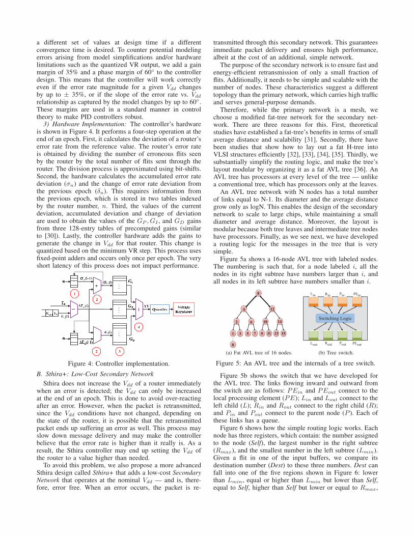
3) Hardware Implementation: The controller’s hardwareis shown in Figure 4. It performs a four-step operation at theend of an epoch. First, it calculates the deviation of a router’serror rate from the reference value. The router’s error rateis obtained by dividing the number of erroneous flits seenby the router by the total number of flits sent through therouter. The division process is approximated using bit-shifts.Second, the hardware calculates the accumulated error ratedeviation (σn) and the change of error rate deviation fromthe previous epoch (δn). This requires information fromthe previous epoch, which is stored in two tables indexedby the router number, n. Third, the values of the currentdeviation, accumulated deviation and change of deviationare used to obtain the values of the GP , GI , and GD gainsfrom three 128-entry tables of precomputed gains (similarto [30]). Lastly, the controller hardware adds the gains togenerate the change in Vdd for that router. This change isquantized based on the minimum VR step. This process usesfixed-point adders and occurs only once per epoch. The veryshort latency of this process does not impact performance.GGGGGGGGG
HI HIJ KJ L M N OJ LJ P Q R SST
SSTP U V W X Y
Z J L M N [ \ OZ J L M N O L M N O] L M N O
^ _^ `a b c d e f g h i N j k l m n o p q rs k t f u g i v wX
x y zxFigure 4: Controller implementation.
B. Sthira+: Low-Cost Secondary Network
Sthira does not increase the Vdd of a router immediatelywhen an error is detected; the Vdd can only be increasedat the end of an epoch. This is done to avoid over-reactingafter an error. However, when the packet is retransmitted,since the Vdd conditions have not changed, depending onthe state of the router, it is possible that the retransmittedpacket ends up suffering an error as well. This process mayslow down message delivery and may make the controllerbelieve that the error rate is higher than it really is. As aresult, the Sthira controller may end up setting the Vdd ofthe router to a value higher than needed.
To avoid this problem, we also propose a more advancedSthira design called Sthira+ that adds a low-cost SecondaryNetwork that operates at the nominal Vdd — and is, there-fore, error free. When an error occurs, the packet is re-
transmitted through this secondary network. This guaranteesimmediate packet delivery and ensures high performance,albeit at the cost of an additional, simple network.
The purpose of the secondary network is to ensure fast andenergy-efficient retransmission of only a small fraction offlits. Additionally, it needs to be simple and scalable with thenumber of nodes. These characteristics suggest a differenttopology than the primary network, which carries high trafficand serves general-purpose demands.
Therefore, while the primary network is a mesh, wechoose a modified fat-tree network for the secondary net-work. There are three reasons for this. First, theoreticalstudies have established a fat-tree’s benefits in terms of smallaverage distance and scalability [31]. Secondly, there havebeen studies that show how to lay out a fat H-tree intoVLSI structures efficiently [32], [33], [34], [35]. Thirdly, wesubstantially simplify the routing logic, and make the tree’slayout modular by organizing it as a fat AVL tree [36]. AnAVL tree has processors at every level of the tree — unlikea conventional tree, which has processors only at the leaves.
An AVL tree network with N nodes has a total numberof links equal to N-1. Its diameter and the average distancegrow only as logN. This enables the design of the secondarynetwork to scale to large chips, while maintaining a smalldiameter and average distance. Moreover, the layout ismodular because both tree leaves and intermediate tree nodeshave processors. Finally, as we see next, we have developeda routing logic for the messages in the tree that is verysimple.
Figure 5a shows a 16-node AVL tree with labeled nodes.The numbering is such that, for a node labeled i, all thenodes in its right subtree have numbers larger than i, andall nodes in its left subtree have numbers smaller than i.
2
4
6
1 3
10
11
12
14
13
8
5 7 9 15
0
(a) Fat AVL tree of 16 nodes.
Switching Logic
PEout Pout Rout Lout
Pin Rin Lin PEin
(b) Tree switch.
Figure 5: An AVL tree and the internals of a tree switch.
Figure 5b shows the switch that we have developed forthe AVL tree. The links flowing inward and outward fromthe switch are as follows: PEin and PEout connect to thelocal processing element (PE); Lin and Lout connect to theleft child (L); Rin and Rout connect to the right child (R);and Pin and Pout connect to the parent node (P ). Each ofthese links has a queue.
Figure 6 shows how the simple routing logic works. Eachnode has three registers, which contain: the number assignedto the node (Self), the largest number in the right subtree(Rmax), and the smallest number in the left subtree (Lmin).Given a flit in one of the input buffers, we compare itsdestination number (Dest) to these three numbers. Dest canfall into one of the five regions shown in Figure 6: lowerthan Lmin, equal or higher than Lmin but lower than Self,equal to Self, higher than Self but lower or equal to Rmax,

and higher than Rmax. Based on where Dest falls in thesefive regions, the flit is routed to the parent, the left subtree,the local node, the right subtree, and the parent, respectively.
Lmin Rmax Self LLmin SelSel RRmaxRRSelf SelSelSel
Send to Lout Send to Rout
Send to Pout
Send to PEout
Send to Pout
Parent Parent Left Sub-tree Right Sub-tree
Send to PE
Figure 6: Simple routing logic for the tree switches.
The secondary network is very lightly used. Hence, weset the bandwidth of the links at the leaves to be 1/8th ofthat of the primary network links. To support the increasingutilization of the links at the upper tree levels, we doublethe width of the links every two levels.
V. DESIGN ISSUES
A. Error Handling
To detect data flit errors, Sthira uses an 8-bit WCDMA-8CRC code [37]. Whenever a flit is corrupted by a router, itfails the CRC at the next router and is dropped. Alternativessuch as SECDED are not suitable for our use because of thepossibility of multi-bit errors at low Vdd. Also, the area andenergy overheads of a multi-bit ECC such as OrthogonalLatin Square Codes go against our primary goal of energyefficiency, considering the small number of errors that wesee in our design. Hence, we use CRC.
Each router has one error counter designated for eachof its neighbors. Whenever a flit from a neighbor is foundfaulty at a router, the corresponding counter is incremented.There are also counters that measure the total number of flitstransmitted through each router. At the end of each epoch,the controller reads all these counters using light-weightcontrol connections (in Sthira) or the secondary network (inSthira+), and makes a decision on the new Vdd to apply.
The source node identifies an error condition using time-outs. A time-out occurs if the source does not receive anacknowledgment (ack) within a certain period. Sthira lever-ages the acks of transactions at the protocol layer (e.g., cachecoherence transactions in shared-memory systems [38]). Ifthe protocol does not have an ack for a given transaction,Sthira adds it. On a time-out, the source assumes the packetis dropped and retransmits the packet on the primary network(Sthira) or secondary one (Sthira+).
In scenarios of network congestion, even though long-duration message stalls are unlikely in NoCs [39], the sourcemight pessimistically assume that a packet is dropped eventhough its flits are progressing slowly through the network.In this case, it re-sends the packet and the destinationreceives two copies of the same packet. By maintaining apair-wise sequence number of the last acknowledged packet,duplicates are identified and dropped at the destination.
An error in control flits may result in misrouting or routingcycles. We implement the detection techniques detailedin [40] to comprehensively identify all such conditions (e.g.,control path and VC bit errors) and drop corrupted flits, sothat the source times-out and retransmits. We include alltheir overheads in our evaluation.
B. Multiple Routers per Vdd Domain
With multiple routers per Vdd domain, the controlleroperates in two steps. First, the controller chooses a Vdd foreach router in the domain after measuring the error rate inthe router. Second, the controller sets the Vdd of the domainto be the maximum of all the chosen Vdds of the routers inthat domain.
Due to this coarse granularity of Vdd control, the energysaved will be lower than with single-router Vdd domains.In reality, due to systematic variations, physically closerouters are similarly affected by process variations, and theiroperational Vdd will likely be close.
C. Controller Characteristics and Aging
As shown in Figure 4, the PID controller is composed oflookup tables and adders. Each table has 128 entries, andeach entry is 15 bits. Consequently, the controller’s area isvery modest. It is a simple circuit, with three adders andone table lookup in its longest path. Moreover, its operationis not time-critical. For example, for a 64-domain network,the controller only needs to operate 64 times every epoch(e.g., every 50 µs).
Over many months of NoC use, the routers may age andchange their speed characteristics slightly. At that point, wemay want to re-profile the routers, recompute the KP ,KI
and KD controller constants, and reprogram the controller.Since aging effects occur at year-level timescale [41], repro-gramming on a yearly basis adds negligible overhead.
D. Costs of the Sthira and Sthira+ Designs
Compared to a standard NoC, a Sthira/Sthira+ system hasfour main costs. Three of them are similar to a state-of-the-art heuristic approach called Tangle [11]; one cost is new.The three similar costs are:
1. Cost of voltage regulation: The multiple Vdd domainsof the NoC are generated by voltage regulators (VRs).As discussed in Section II-C, VRs induce a power loss,but there are many different designs and the technologyis evolving. Using data from the recent IBM POWER8demonstration [22], we assume that providing multiple Vdd
domains in the NoC wastes 10% of the NoC power.2. Cost of error detection and counting: Our results in the
evaluation include the energy and performance overheads ofusing link-level CRC and error counters in each router. Theperformance overhead of using CRC is negligible: it addsonly one extra cycle for encoding at the source node, whilethe checking is done in parallel with flit processing at eachof the routers in the flit’s path.
3. Cost of retransmission buffers: The retransmissionbuffers that temporarily store transmitted packets at thesource to enable retransmission in case of a fault, consumearea and power. They may also cause a stall if they becomefull. Our results include the impact of these buffers.
The new cost is the formal controller system. In addi-tion, for Sthira+, another cost is the secondary network,which replaces Sthira’s control links between controllerand routers. The formal controller and secondary networkparameters are listed in Section VI. These two componentsintroduce small overheads. We estimate that, on average,the controller introduces less than a 1% energy overhead to

Table I: Architecture and variation parameters. For thememory hierarchy, we give round-trip latencies from thecore.
Core Parameters
Frequency 1 GHz
Fetch, issue, and commit 2 per cycle
ROB; Ld/St queue 64 entries; 16/16 entries
Issue queue; I-fetch queue 64 entries; 32 entries
Branch (BR) predictor Tournament (bimodal + 2-level)
BTB; history table 1024 entries, 2-way; 2048 entries
Memory System Parameters
L1 data cache 32KB, 2-way, 2 cyc. latency, 64B line
L1 instr. cache 32KB, 2-way, 2 cyc. latency, 64B line
L2 cache 32MB shared, 64-bank static addr.
L2 cache bank 8-way, 64B line, 6 cyc. latency (local)
Main memory 260 cyc. latency, 4 mem. controllers
Main Network-on-Chip Parameters
Topology; routing 8x8 2D-mesh; X-Y routing, wormhole
Num. virtual channels 4 per physical channel
Buffer depth per virtual channel 4
Min. Vdd tuning step 10mV , 20 cycles latency
Retransmission buffer depth 8
Link width 128b
Nominal Vdd 825mV (10% guardband)
Length of an epoch 50,000 cycles (min.)
Num. routers in Vdd domain From 1 to 64; 1 is default
Penalty to Sthira/Sthira+ NoCs 10% power due to Vdd regulation
Secondary Network Parameters
Topology AVL Tree
Routing Least Common Ancestor routing
Link width 16b (lowest level), double every 2 levels
Number of buffers One per link
Buffer depth 1
Nominal Vdd 825mV
Process Variation Parameters
Tech. node; Vdd guardband 11nm; 10%
Total Vth (σ/µ) 12.5% (equal random & systematic)
Total Leff (σ/µ) 6.25% (equal random & systematic)
Correlation range φ 0.1 (for both Vth and Leff )
the NoC (most of it static), while the secondary networkintroduces a 1.7% energy overhead (with comparable staticand dynamic components). Our results in the evaluationinclude the energy and performance overheads introducedby these two components.
VI. EXPERIMENTAL METHODOLOGY
To evaluate the energy and performance of Sthira/Sthira+,we use several tools. First, we take the Verilog imple-mentation of a wormhole-switched virtual channel routerfrom [42], and develop a 3-stage look-ahead router similar tothat proposed in [43]. Using the Synopsys Design Compiler,we perform timing analysis on this design to extract the 32slowest paths and their netlists, for each stage. We use a3-stage router instead of a more aggressive single-cycle onefor two reasons. First, single-cycle routers tend to operateat slower clock rates. Second, they often rely on speculativeoperation, which makes them less energy efficient [44]. Aswe explore a futuristic chip design, we perform processvariation modeling at 11nm using VARIUS-NTV [15]. Thebaseline chip comprises 64 nodes with private L1 caches, 64routers with virtual channels, and 64 banks of a shared L2.To obtain the timing failure rates due to process variation,we first generate the chip floorplan. Next, the logical effortsextracted from the synthesis phase are used to enable a betterdelay modeling of the different stages of routers.
To obtain performance and energy consumption metrics,we use a cycle-level microarchitectural simulator of a mul-tiprocessor chip with an NoC [40], [45]. Table I shows thearchitecture parameters. The baseline design of the mainnetwork has 64 routers in an 8x8 2D-mesh. Each routeris associated with a core. A router has 5 physical channels(PCs), including the port from the local core to the router.There are 4 virtual channels (VCs) per PC — which areenough to avoid deadlocks. Each VC has a buffer depth of4 flits. We use a wormhole-switched 2D-mesh network withdeterministic X-Y routing (guaranteeing deadlock freedom)that uses credit-based flow control. The secondary networkis a fat AVL tree. The router is implemented in structuralRTL Verilog and synthesized using the Synopsys DesignCompiler with Nangate 45nm open cell library. Based onrules given in [46] and technology parameters from the ITRSreport [47], we scale it down to 11nm.
The simulator also models the cores and caches. The coresare 2-issue out-of-order Alpha DEC EV4-like cores. Theirfrequency is 1GHz to save power and enable operation undera typical power envelope. Similar low frequencies have beenused by researchers for large CMPs [40], [48].
We explore network configurations with 1 to 64 routersper Vdd domain. In the evaluation, the default system has 1router per Vdd domain. We also vary the network size from4x4 to 10x10 nodes. For each network, we use VARIUS-NTV to generate chips with representative variation profiles.
To estimate the static and dynamic power in the routerbuffers, crossbar, and clock distribution, we use our synthesisresults from the Synopsys Design Compiler. The resultsagree with those in DSENT [49] generated by SPICE. Forexample, our synthesis experiments estimate 6.54mW forthe power in the router buffers; DSENT reports 6.93mW .
We use MATLAB to obtain the linearized error probabilityas a function of router Vdd, and design the controller. Usingpole-zero analysis, we find the values for KP ,KI ,KD thatresult in a stable controller with acceptable overshoots andundershoots (Section IV-A2).
For our experiments, we run 10 multi-programmed work-loads. They are a subset of those used in [39]. Of theseworkloads, 3 are commercial (sap, sjas, and tpcw), 4 areengineering (429.mcf, 437.leslie3d, 459.GemsFDTD, and483.xalancbmk) and 3 are scientific (art, ocean, and swim).We use SimPoint [50] to select representative windows ofinstructions for simulation, and we simulate about 10Minstructions per thread after warm-up. In the experiments, weuse a source time-out threshold of three times the round-triplatency, a target error rate of 0.05%, and an epoch durationof 50,000 processor cycles.
Our evaluation compares the energy consumption, per-formance, and error rates of the five NoC architectures ofTable II. These architectures include, in addition to Sthiraand Sthira+: (1) a nominal-Vdd plain NoC with a single Vdd
domain (Baseline); (2) Tangle [11]; and (3) an enhancedversion of Tangle where, on an error, only the erroneousrouter changes Vdd, not all routers in the flit path as Tangledoes. This version is called Tangle+, and is an ad-hocscheme that is more aggressive than Tangle and closer toSthira.
In Tangle and Tangle+, we use a fixed Vdd tuning stepof 10mV . While [11] uses a variable step size, it requires

Tangle Tangle+ Sthira Sthira+0
5
10
15
20
25
30
35
En
erg
yS
avin
gs
(%)
64 100
(a) Energy savings.
Tangle Tangle+ Sthira Sthira+0.00
0.05
0.10
0.15
0.20
0.25
0.30
0.35
Avg.
Err
or
Rate
(%)
64
100
(b) Average error rate.
Tangle Tangle+ Sthira Sthira+0
1
2
3
4
5
Perf
orm
an
ceO
verh
ead
(%) 64
100
(c) Performance overhead.
Tangle Tangle+ Sthira Sthira+0.0
0.2
0.4
0.6
0.8
1.0
Max.
Err
or
Rate
(%)
(d) Maximum error rate.
Figure 7: Comparing the energy savings, average error rate, performance overhead, and maximum error rate of the differentarchitectures. Energy savings and performance overhead are normalized to the NoC without Vdd reduction (Baseline). Thefigure shows data for 64- and 100-router NoCs.
0 50 100 150 2000.50
0.55
0.60
0.65
0.70
0.75
0.80
Volt
age
(V)
(a) Sthira+.
0 50 100 150 2000.50
0.55
0.60
0.65
0.70
0.75
0.80
Volt
age
(V)
(b) Sthira.
0 50 100 150 2000.50
0.55
0.60
0.65
0.70
0.75
0.80
Volt
age
(V)
(c) Tangle+.
0 50 100 150 2000.50
0.55
0.60
0.65
0.70
0.75
0.80
Volt
age
(V)
(d) Tangle.
Figure 8: Variation in the Vdd of each router over time (in epochs) in a 64-router NoC running the GemsFDTD application.Note that both voltage regulators in the hierarchical VR contribute to the voltage reduction.
Table II: NoC architectures compared.
Name Architecture
Baseline Nominal-Vdd plain NoC with a single Vdd domain.Tangle Tangle as described in [11].Tangle+ Tangle except that, on an error, only the erroneous
router changes Vdd, not all routers in the flit path.Sthira Proposed Sthira architecture.Sthira+ Proposed Sthira architecture plus the secondary network.
prior knowledge of a “convergence voltage” VAvgTest. Weconsider that such Vdd is not known for a variation-affectedsystem. In any case, this change has minimal impact becauseit only affects the initial Vdd changes.
VII. EVALUATION
A. Comparing the Different Schemes
We start the evaluation by comparing the schemes inTable II. Figure 7 compares them under four metrics: energysavings (a), average error rate (b), performance overhead (c),and maximum error rate (d). The figure shows data for 64-and 100-router NoCs. Next, we consider each metric in turn.
1) Comparing Energy Savings: Figure 7(a) shows theNoC energy savings relative to an NoC without Vdd reduc-tion (Baseline). The data corresponds to the average of allthe applications. We see that Sthira+ saves 36-37% of theNoC energy, while Sthira saves 32%. Tangle+ saves about30% of the energy, and Tangle only saves 23%.
Sthira+ saves the most because it uses its advanced hard-ware (including the secondary network) to control Vdd well,and keep it the lowest. Sthira also has a formal controller,which helps it reduce the Vdd. However, on an error, themessage is retransmitted on the same network. Since theVdd of the routers is not changed until the beginning of the
next epoch, the retransmitted message may suffer the sameerror again. As a result, Sthira will converge to a slightlyhigher Vdd — hence, saving less energy.
Tangle follows a different approach. As soon as a routerdetects an error, Tangle increases the Vdd without waitingfor the epoch to complete. Moreover, Tangle increases theVdd of all the routers in the path of the flit. As a result, theerror rate will be low. However, the lack of formal controlresults in Vdd values that are higher than the other schemes.Consequently, Tangle saves the least energy.
Tangle+ follows the same eager approach as Tangle toincrease the Vdd of a router immediately when an error isdetected. However, it only increases the Vdd of that router.Hence, the energy savings are higher than in Tangle.
The impact of the different schemes on Vdd is shown inFigure 8. The figure has one plot per scheme, which showsthe variation of the Vdd of each router over time (in epochs)in a 64-router NoC running the GemsFDTD application.Each plot also shows the average Vdd as a thicker line.
From the plots, we see that the steady-state average Vdd
goes up from Sthira+ to Sthira, Tangle+, and Tangle. Thischange broadly explains the difference in energy savings inFigure 7(a). In addition, the plots show the very differentconvergence behavior of Sthira+ and Sthira on the onehand, and of Tangle+ and Tangle on the other. Specifically,in Sthira+ and Sthira, the Vdd of each router convergessmoothly. This is thanks to the formal controller. However, inTangle+ and Tangle, the Vdd of each router keeps oscillating.This produces suboptimal Vdd values — sometimes too highand therefore wasteful, and sometimes too low and so error-inducing.
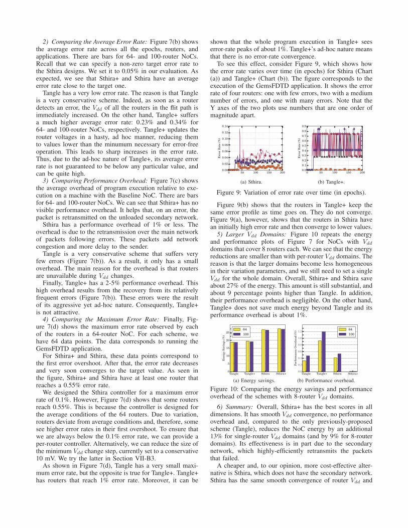
2) Comparing the Average Error Rate: Figure 7(b) showsthe average error rate across all the epochs, routers, andapplications. There are bars for 64- and 100-router NoCs.Recall that we can specify a non-zero target error rate tothe Sthira designs. We set it to 0.05% in our evaluation. Asexpected, we see that Sthira+ and Sthira have an averageerror rate close to the target one.
Tangle has a very low error rate. The reason is that Tangleis a very conservative scheme. Indeed, as soon as a routerdetects an error, the Vdd of all the routers in the flit path isimmediately increased. On the other hand, Tangle+ suffersa much higher average error rate: 0.23% and 0.34% for64- and 100-router NoCs, respectively. Tangle+ updates therouter voltages in a hasty, ad hoc manner, reducing themto values lower than the minumum necessary for error-freeoperation. This leads to sharp increases in the error rate.Thus, due to the ad-hoc nature of Tangle+, its average errorrate is not guaranteed to be below any particular value, andcan be quite high.
3) Comparing Performance Overhead: Figure 7(c) showsthe average overhead of program execution relative to exe-cution on a machine with the Baseline NoC. There are barsfor 64- and 100-router NoCs. We can see that Sthira+ has novisible performance overhead. It helps that, on an error, thepacket is retransmitted on the unloaded secondary network.
Sthira has a performance overhead of 1% or less. Theoverhead is due to the retransmission over the main networkof packets following errors. These packets add networkcongestion and more delay to the sender.
Tangle is a very conservative scheme that suffers veryfew errors (Figure 7(b)). As a result, it only has a smalloverhead. The main reason for the overhead is that routersare unavailable during Vdd changes.
Finally, Tangle+ has a 2-5% performance overhead. Thishigh overhead results from the recovery from its relativelyfrequent errors (Figure 7(b)). These errors were the resultof its aggressive yet ad-hoc nature. Consequently, Tangle+is not attractive.
4) Comparing the Maximum Error Rate: Finally, Fig-ure 7(d) shows the maximum error rate observed by eachof the routers in a 64-router NoC. For each scheme, wehave 64 data points. The data corresponds to running theGemsFDTD application.
For Sthira+ and Sthira, these data points correspond tothe first error overshoot. After that, the error rate decreasesand very soon converges to the target value. As seen inthe figure, Sthira+ and Sthira have at least one router thatreaches a 0.55% error rate.
We designed the Sthira controller for a maximum errorrate of 0.1%. However, Figure 7(d) shows that some routersreach 0.55%. This is because the controller is designed forthe average conditions of the 64 routers. Due to variation,routers deviate from average conditions and, therefore, somesee higher error rates in their first overshoot. To ensure thatwe are always below the 0.1% error rate, we can provide aper-router controller. Alternatively, we can reduce the size ofthe minimum Vdd change step, currently set to a conservative10 mV. We try the latter in Section VII-B3.
As shown in Figure 7(d), Tangle has a very small maxi-mum error rate, but the opposite is true for Tangle+. Tangle+has routers that reach 1% error rate. Moreover, it can be
shown that the whole program execution in Tangle+ seeserror-rate peaks of about 1%. Tangle+’s ad-hoc nature meansthat there is no error-rate convergence.
To see this effect, consider Figure 9, which shows howthe error rate varies over time (in epochs) for Sthira (Chart(a)) and Tangle+ (Chart (b)). The figure corresponds to theexecution of the GemsFDTD application. It shows the errorrate of four routers: one with few errors, two with a mediumnumber of errors, and one with many errors. Note that theY axes of the two plots use numbers that are one order ofmagnitude apart.
0 50 100 150 2000.00
0.02
0.04
0.06
0.08
0.10
0.12
0.14
Error
Rate
(%)
(a) Sthira.
0 50 100 150 2000.0
0.1
0.2
0.3
0.4
0.5
0.6
0.7
0.8
0.9
Error
Rate
(%)
(b) Tangle+.
Figure 9: Variation of error rate over time (in epochs).
Figure 9(b) shows that the routers in Tangle+ keep thesame error profile as time goes on. They do not converge.Figure 9(a), however, shows that the routers in Sthira havean initially high error rate and then converge to lower values.
5) Larger Vdd Domains: Figure 10 repeats the energyand performance plots of Figure 7 for NoCs with Vdd
domains that cover 8 routers each. We can see that the energyreductions are smaller than with per-router Vdd domains. Thereason is that the larger domains become less homogeneousin their variation parameters, and we still need to set a singleVdd for the whole domain. Overall, Sthira+ and Sthira saveabout 27% of the energy. This amount is still substantial, andabout 9 percentage points higher than Tangle. In addition,their performance overhead is negligible. On the other hand,Tangle+ does not save much energy beyond Tangle and itsperformance overhead is about 1%.
Tangle Tangle+ Sthira Sthira+0
5
10
15
20
25
En
erg
yS
avin
gs
(%)
64
100
(a) Energy savings.
Tangle Tangle+ Sthira Sthira+0.0
0.2
0.4
0.6
0.8
1.0
1.2
Perf
orm
an
ceO
verh
ead
(%) 64
100
(b) Performance overhead.
Figure 10: Comparing the energy savings and performanceoverhead of the schemes with 8-router Vdd domains.
6) Summary: Overall, Sthira+ has the best scores in alldimensions. It has smooth Vdd convergence, no performanceoverhead and, compared to the only previously-proposedscheme (Tangle), reduces the NoC energy by an additional13% for single-router Vdd domains (and by 9% for 8-routerdomains). Its effectiveness is in part due to the secondarynetwork, which highly-efficiently retransmits the packetsthat failed.
A cheaper and, to our opinion, more cost-effective alter-native is Sthira, which does not have the secondary network.Sthira has the same smooth convergence of router Vdd and
error rates as Sthira+, thanks to a formal controller. Itsenergy savings and performace overhead are slightly lessfavorable. Still, compared to Tangle, Sthira has the sameminimal performance overhead and reduces the NoC energyby an additional 9% for single-router Vdd domains (and by9% for 8-router domains).
Tangle+ is not attractive. While, for single-router domains,it saves nearly as much energy as Sthira, it slows downexecution by 2-5%. In addition, even in steady state, itsuffers large oscillations in error rate and, to a lesser degree,Vdd. Further, it provides no guarantees on error-rate limits.
B. Sthira/Sthira+ Characterization
We now examine some aspects of Sthira and Sthira+.
1) Energy Savings for Different NoC Sizes: The carefuldesign of the controller in Sthira and Sthira+ enables thesearchitectures to retain the energy savings (about 32% and37%, respectively) across NoC sizes, as shown in Figure 11a.Due to its advanced design, Sthira+ is able to save moreenergy than Sthira for all network sizes.
16 36 64 1000
5
10
15
20
25
30
35
40
En
erg
yS
avin
gs
(%)
Sthira
Sthira+
(a) Across NoC sizes.
1 4 16 640
5
10
15
20
25
30
35
40
En
erg
yS
avin
gs
(%)
Sthira
Sthira+
(b) Across Vdd domain sizes.
Figure 11: Energy Savings across NoC sizes and Vdd domainsizes in Sthira and Sthira+
2) Energy Savings for Different Vdd Domain Sizes: Theenergy savings is expected to reduce with increasing sizeof the Vdd domains in the chip. With larger Vdd domains,the Vdd of an entire domain is set conservatively to themaximum of the Vdd of all the routers in the domain. Hence,the savings decrease as shown in Figure 11b. From thisfigure, it can also be seen that, even in the case of a singleVdd domain for the entire chip (i.e., size of 64), Sthira andSthira+ are able to save 19-20% of the NoC energy.
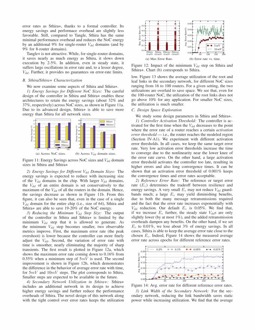
3) Reducing the Minimum Vdd Step Size: The outputof the controller in Sthira and Sthira+ is limited by theminimum Vdd step that it is allowed to generate. Asthe minimum Vdd step becomes smaller, two observablemetrics improve. First, the maximum error rate (the peakovershoot) is lower because the controller can more finelyadjust the Vdd. Second, the variation of error rate withtime is smoother, nearly eliminating the majority of sharptransients. The first result is plotted in Figure 12a, whichshows the maximum error rate coming down to 0.16% from0.55% when a minimum step of 5mV is used. The secondimprovement is shown in Figure 12b, which demonstratesthe difference in the behavior of average error rate with time,for 5mV and 10mV steps. The plot corresponds to Sthira.Smaller steps are expected to be available in the future.
4) Secondary Network Utilization in Sthira+: Sthira+includes an additional network in its design to achievehigher energy savings and further reduce the performanceoverheads of Sthira. The novel design of this network alongwith the tight control over error rates keeps the utilization
Sthira
(5 mV)
Sthira
(10 mV)
Sthira+
(5 mV)
Sthira+
(10 mV)
0.0
0.1
0.2
0.3
0.4
0.5
Max.
Error
Rate
(%)
(a) Max Error Rate.
0 50 100 150 2000.00
0.01
0.02
0.03
0.04
0.05
Avg.
Err
or
Rate
(%)
5 mV
10 mV
(b) Error rate vs. time.
Figure 12: Impact of the minimum Vdd step on Sthira andSthira+. Chart (b) corresponds to Sthira.
low. Figure 13 shows the average utilization of the root andleaf links in the secondary network, for different NoC sizesranging from 16 to 100 routers. For a given setting, the twoutilizations are overlaid to save space. We see that, even forthe 100-router NoC, the utilization of the root links does notgo above 10% for any application. For smaller NoC sizes,the utilization is much smaller.
C. Design Space Exploration
We study some design parameters in Sthira and Sthira+.1) Controller Activation Threshold: The controller is ac-
tivated for the first time when the Vdd decreases to the pointwhere the error rate of a router reaches a certain activationerror threshold — i.e., the router reaches the modeled region(Section IV-A1). We experiment with different activationerror thresholds. In all cases, we keep the same target errorrate. Very low activation error thresholds increase the timeto converge due to the nonlinearity near the lower knee ofthe error rate curve. On the other hand, a large activationerror threshold activates the controller too late, resulting inhigher errors and also long convergence times. It can beshown that an activation error threshold of 0.001% keepsthe convergence times and error rates acceptable.
2) Reference Error Rate: The reference or target errorrate (E◦) determines the tradeoff between resilience andenergy savings. A very small E◦ may not reduce Vdd guard-bands much; a large E◦ may yield diminishing benefits,due to both the many message retransmissions requiredand the fact that the error rate increases exponentially withVdd reduction. Our default E◦ is 0.05%. We find that,if we increase E◦ further, the steady state Vdds are onlyslightly lower (by at most 1%), and the added retransmissionoverheads dampen any benefits. On the other hand, if we setE◦ to 0.01%, we lose about 3% of energy savings. In allcases, Sthira is able to keep the average error rate close to thechosen E◦. Indeed, Figure 14 shows the measured averageerror rate across epochs for different reference error rates.
0 50 100 150 2000.00
0.05
0.10
0.15
0.20
0.25
Avg.
Err
or
Rate
(%)
0.2% 0.1% 0.05% 0.01%
Figure 14: Avg. error rate for different reference error rates.
3) Link Width of the Secondary Network: For the sec-ondary network, reducing the link bandwidth saves staticpower while increasing utilization. We find that the average

{|}~�� {� �� � � � � � � { { � � � � � � � { { � � � � � � � { { � � � � � � � { { � � � � � � � { { � � � � � � � { { � � � � � � � { { � � � � � � � { { � � � � � � � { { � � � � � � � { { � � � � � � � { {� � � � � � � � � � � � � � � � � � � � � � � � � � � � � � � � � � � � � � � � � � � � � � � � � � � � � � � � � � ¡¢ £¤ ¥¦§¦ ©¥¦ ª«¬® ¯ ° ° ± ² ³ ´ µ ³ ¶
Figure 13: Average utilization of the root and leaf links in the secondary network for different NoC sizes. For a given setting,the two utilizations are overlaid to save space.
utilization of the secondary network at the root node growsonly slowly, and stays below 10% for link widths no lowerthan the ones we use as baseline. However, if we furtherreduce the link widths by half, the average utilization at theroot links can go up to 26% for some applications.
4) Fat-Tree Bandwidth: To reduce congestion in a fattree, the bandwidth of the links is gradually increased asthe links get closer to the root level. In Sthira+, maintaininga constant link bandwidth causes the average utilizationat the root level to reach 35%, resulting in a noticeableperformance overhead. Doubling the bandwidth at everylevel brings down the utilization to less than 1%, butincreases area and energy. Hence, we choose to doublethe bandwidth every other layer. This balances the energy-utilization tradeoff.
D. Discussion: Other Sources of Variation
This paper focused on reducing Vdd guardbands added toaddress process variation and, potentially, circuit wearout.However, the control-theoretic design of the controller canpotentially allow it to adapt to more dynamic changes —e.g., temperature changes due to workload variations. In suchscenarios, a controller could be designed to dynamicallylearn and adapt Vdd to these changes. A detailed analysisof such scenarios is beyond the scope of this paper.
VIII. RELATED WORK
The impact of process variation on NoCs has been studiedby Nicopoulos et al. using rigorous circuit analysis [51].Their analysis does not include a fault model or the impactof faults at the system level. In [7], Li et al. show that a highdegree of process variation can force major design modifica-tions to the underlying network architecture. Ogras et al. [52]explore the effectiveness of multiple Vdd-frequency domainsin NoCs when dealing with a deep sub-micron process.Lefurgy et al. [16] use a feedback regulator to reduce theVdd guardbands by continuously monitoring the availabletiming margin. Such approach requires continuous pipelinemonitoring, and responds immediately on an event.
Some proposals compensate for the timing variations oflinks by time borrowing or cycle tuning [53], [54]. Timeborrowing/stealing is a technique that has been used totackle process variations in the processor pipeline [55],[56], [57]. Such techniques are mostly applied statically, atmanufacturing time and require circuit-level modification tothe underlying router design. This limits these techniques inadapting to the runtime conditions of the system.
Many techniques have been proposed to improve thefault tolerance of both links and routers in the presence
of permanent and transient faults [40], [58], [59]. Thesesolutions may incur higher overheads as they are proactive,and tackle all types of faults in the same way. Our goal is toadjust the circuit parameters to address only timing failures.
Pothukuchi et al. [23] advocate the general use of control-theoretic methodologies in controllers to meet multiple ob-jectives in processors. The application of control theory tosave power is explored by Wu et al. [30] in multiple clockdomain processors, and by Raghavendra et al. [60] in datacenters. We have used some of their insights. However, wefocus on a different domain, namely NoC routers. Also,unlike [30], [60], we do not assume multiple frequencydomains, since they necessitate the use of asynchronousqueues to communicate across domains.
Chen et al. [61] use a PI controller to set the uncore DVFS.They measure the memory access time as a function of fre-quency for some programs and generate a PI controller. Weuse control theory for a different goal: to reduce wasteful Vdd
guardbands arising from process variations. Consequently,our approach and design are different.
IX. CONCLUSION
This paper presented Sthira, a scheme that dynamicallyminimizes the Vdd of groups of routers in a variation-prone NoC at constant frequency using formal control-theorymethods. We also enhanced Sthira with a low-cost secondarynetwork that retransmits faulty packets for higher energyefficiency. The enhanced scheme is called Sthira+.
We evaluated Sthira and Sthira+ with simulations of NoCswith 64–100 routers, and compared them to state-of-the-art designs. In an NoC with 8 routers per Vdd domain,our schemes reduced the average energy consumption ofa conventional NoC by 27%; in a futuristic NoC withone router per Vdd domain, Sthira+ and Sthira reducedthe average energy consumption of a conventional NoCby 36% and 32%, respectively. The performance impactwas negligible. These savings are obtained after taking intoaccount the power losses in voltage regulators, and are 9–13 percentage points higher than in the best existing adhoc proposals. Moreover, we showed that formal control isessential to provide guarantees on the convergence, stability,and maximum resulting error rates. Finally, while the sec-ondary network helped Sthira+ attain higher energy savings,it has a non-negligible hardware cost. Hence, Sthira is themost cost-effective design.
ACKNOWLEDGMENTS
This work was supported in part by NSF under grantsCCF-1536795 and CCF-1649432.
REFERENCES
[1] S. Y. Borkar, “Designing Reliable Systems from UnreliableComponents: The Challenges of Transistor Variability andDegradation,” IEEE Micro, 2005.
[2] ——, “Future of Interconnect Fabric: A Contrarian View,” inSLIP, 2010.
[3] N. Carter, A. Agrawal, S. Borkar, R. Cledat, H. David,D. Dunning, J. Fryman, I. Ganev, R. Golliver, R. Knauerhase,R. Lethin, B. Meister, A. Mishra, W. Pinfold, J. Teller,J. Torrellas, N. Vasilache, G. Venkatesh, and J. Xu, “Run-nemede: An Architecture for Ubiquitous High-PerformanceComputing,” in HPCA, Feb. 2013.
[4] S. Dighe, S. Vangal, P. Aseron, S. Kumar, T. Jacob, K. Bow-man, J. Howard, J. Tschanz, V. Erraguntla, N. Borkar,V. De, and S. Borkar, “Within-Die Variation-Aware Dynamic-Voltage-Frequency-Scaling With Optimal Core Allocationand Thread Hopping for the 80-Core TeraFLOPS Processor,”IEEE J. Solid-State Circuits, vol. 46, no. 1, pp. 184–193,2011.
[5] X. Fu, T. Li, and J. A. B. Fortes, “Architecting Reliable Multi-core Network-on-chip for Small Scale Processing Technol-ogy,” in DSN, 2010.
[6] J. Howard, S. Dighe, S. Vangal, G. Ruhl, N. Borkar, S. Jain,V. Erraguntla, M. Konow, M. Riepen, M. Gries, G. Droege,T. Lund-Larsen, S. Steibl, S. Borkar, V. De, and R. VanDer Wijngaart, “A 48-Core IA-32 Processor in 45 nm CMOSUsing On-Die Message-Passing and DVFS for Performanceand Power Scaling,” IEEE J. Solid-State Circuits, vol. 46,no. 1, pp. 173 –183, 2011.
[7] B. Li, L.-S. Peh, and P. Patra, “Impact of Process and Tem-perature Variations on Network-on-Chip Design Exploration,”in NOCS, 2008.
[8] S. Hemmert, “From Petascale to Exascale: R & D Challengesfor HPC Simulation Environments,” Hardware ArchitectureWhite Paper, Mar. 2011.
[9] D. Ernst, N. S. Kim, S. Das, S. Pant, R. Rao, T. Pham,C. Zeisler, D. Blaauw, T. Austin, K. Flautner, and T. Mudge,“Razor: A Low-Power Pipeline Based on Circuit-Level Tim-ing Speculation,” in MICRO, Dec. 2003.
[10] B. Greskamp, L. Wan, U. R. Karpuzcu, J. J. Cook, J. Torrellas,D. Chen, and C. B. Zilles, “Blueshift: Designing Processorsfor Timing Speculation from the Ground Up,” in HPCA, 2009.
[11] A. Ansari, A. Mishra, J. Xu, and J. Torrellas, “Route-Oriented Dynamic Voltage Minimization for Variation-Afflicted, Energy-Efficient On-Chip Networks,” in HPCA,2014.
[12] A. Bacha and R. Teodorescu, “Dynamic Reduction of VoltageMargins by Leveraging On-chip ECC in Itanium II Proces-sors,” in ISCA, 2013.
[13] ——, “Using ECC Feedback to Guide Voltage Speculation inLow-Voltage Processors,” in MICRO, 2014.
[14] X. Liang, R. Canal, G.-Y. Wei, and D. Brooks, “Replacing 6TSRAMs with 3T1D DRAMs in the L1 Data Cache to CombatProcess Variability,” IEEE Micro, vol. 28, no. 1, pp. 60–68,Jan. 2008.
[15] U. R. Karpuzcu, K. B. Kolluru, N. S. Kim, and J. Torrellas,“VARIUS-NTV: A Microarchitectural Model to Capture theIncreased Sensitivity of Manycores to Process Variations atNear-Threshold Voltages,” in DSN, 2012.
[16] C. R. Lefurgy, A. J. Drake, M. S. Floyd, M. S. Allen-Ware,B. Brock, J. A. Tierno, and J. B. Carter, “Active Managementof Timing Guardband to Save Energy in POWER7,” inMICRO, 2011.
[17] C. Wilkerson, A. R. Alameldeen, Z. Chishti, W. Wu, D. So-masekhar, and S.-L. Lu, “Reducing Cache Power with Low-Cost, Multi-bit Error-Correcting Codes,” in ISCA, 2010.
[18] L. Chang, R. Montoye, B. Ji, A. Weger, K. Stawiasz, andR. Dennard, “A Fully-Integrated Switched-Capacitor 2:1 Volt-
age Converter with Regulation Capability and 90% Efficiencyat 2.3A/mm2,” in VLSIC, Jun. 2010.
[19] “Intel R© Xeon R© Processor E3-1200 v3 Product FamilyDatasheet,” http://www.intel.com/content/dam/www/public/us/en/documents/datasheets/xeon-e3-1200v3-vol-1-datasheet.pdf, Jul. 2014.
[20] H. R. Ghasemi, A. Sinkar, M. Schulte, and N. S. Kim,“Cost-Effective Power Delivery to Support Per-Core VoltageDomains for Power-Constrained Processors,” in DAC, Jun.2012.
[21] F. Ishihara, F. Sheikh, and B. Nikolic, “Level conversion fordual-supply systems,” IEEE Trans. VLSI Syst., vol. 12, no. 2,pp. 185–195, Feb. 2004.
[22] E. Fluhr, S. Baumgartner, D. Boerstler, J. Bulzacchelli,T. Diemoz, D. Dreps, G. English, J. Friedrich, A. Gattiker,T. Gloekler, C. Gonzalez, J. Hibbeler, K. Jenkins, Y. Kim,P. Muench, R. Nett, J. Paredes, J. Pille, D. Plass, P. Restle,R. Robertazzi, D. Shan, D. Siljenberg, M. Sperling, K. Staw-iasz, G. Still, Z. Toprak-Deniz, J. Warnock, G. Wiedemeier,and V. Zyuban, “The 12-Core POWER8TM Processor With7.6 Tb/s IO Bandwidth, Integrated Voltage Regulation, andResonant Clocking,” IEEE J. Solid-State Circuits, vol. 50,no. 1, pp. 10–23, Jan. 2015.
[23] R. P. Pothukuchi, A. Ansari, P. Voulgaris, and J. Torrellas,“Using Multiple Input, Multiple Output Formal Control toMaximize Resource Efficiency in Architectures,” in ISCA,2016.
[24] S. Skogestad and I. Postlethwaite, Multivariable FeedbackControl: Analysis and Design. John Wiley & Sons, 2005.
[25] E. W. Weisstein. ”Erf.” From MathWorld–A Wol-fram Web Resource. [Online]. Available: http://mathworld.wolfram.com/Erf.html
[26] ——. ”Gompertz Curve.” From MathWorld–A Wol-fram Web Resource. [Online]. Available: http://mathworld.wolfram.com/GompertzCurve.html
[27] ——. ”Logistic Distribution.” From MathWorld–AWolfram Web Resource. [Online]. Available: http://mathworld.wolfram.com/LogisticDistribution.html
[28] ——. ”Sigmoid Function. From MathWorld – AWolfram Web Resource”. [Online]. Available: http://mathworld.wolfram.com/SigmoidFunction.html.
[29] G. C. Goodwin, S. F. Graebe, and M. E. Salgado, ControlSystem Design, 1st ed. Upper Saddle River, NJ, USA:Prentice Hall PTR, 2000.
[30] Q. Wu, P. Juang, M. Martonosi, and D. W. Clark, “FormalOnline Methods for Voltage/Frequency Control in MultipleClock Domain Microprocessors,” in ASPLOS, 2004.
[31] C. E. Leiserson, “Fat-trees: Universal Networks forHardware-efficient Supercomputing,” IEEE Trans. Comput.,vol. 34, no. 10, pp. 892–901, Oct. 1985.
[32] D. Ludovici, F. Gilabert, S. Medardoni, C. Gomez,M. Gomez, P. Lopez, G. N. Gaydadjiev, and D. Bertozzi,“Assessing Fat-tree Topologies for Regular Network-on-chipDesign under Nanoscale Technology Constraints,” in DATE,2009.
[33] H. Matsutani, M. Koibuchi, and H. Amano, “Performance,Cost, and Energy Evaluation of Fat H-Tree: A Cost-EfficientTree-Based On-Chip Network,” in IPDPS, Mar. 2007.
[34] H. Matsutani, M. Koibuchi, Y. Yamada, D. Hsu, andH. Amano, “Fat H-Tree: A Cost-Efficient Tree-Based On-Chip Network,” IEEE Trans. Parallel Distrib. Syst., vol. 20,no. 8, pp. 1126–1141, Aug. 2009.
[35] Z. Wang, J. Xu, X. Wu, Y. Ye, W. Zhang, M. Nikdast,X. Wang, and Z. Wang, “Floorplan Optimization of Fat-TreeBased Networks-on-Chip for Chip Multiprocessors,” IEEETrans. Comput., vol. 99, p. 1, 2012.
[36] G. M. Adel’son-Vel’sky and Y. M. Landis, “An Algorithmfor the Organization of Information,” Doklady Akademii Nauk

USSR, vol. 146, no. 2, pp. 263–266, 1962.
[37] P. Koopman and T. Chakravarty, “Cyclic Redundancy Code(CRC) Polynomial Selection For Embedded Networks,” inDSN, 2004.
[38] D. Lenoski, J. Laudon, K. Gharachorloo, A. Gupta, andJ. Hennessy, “The Directory-based Cache Coherence Protocolfor the DASH Multiprocessor,” in ISCA, May 1990, pp. 148–159.
[39] A. K. Mishra, N. Vijaykrishnan, and C. R. Das, “A Case forHeterogeneous On-chip Interconnects for CMPs,” in ISCA,2011.
[40] D. Park, C. Nicopoulos, J. Kim, N. Vijaykrishnan, and C. R.Das, “Exploring Fault-Tolerant Network-on-Chip Architec-tures,” in DSN, 2006.
[41] K. Bhardwaj, K. Chakraborty, and S. Roy, “Towards GracefulAging Degradation in NoCs Through an Adaptive RoutingAlgorithm,” in DAC, Jun. 2012.
[42] L.-S. Peh and W. J. Dally, “A Delay Model and SpeculativeArchitecture for Pipelined Routers,” in HPCA, 2001.
[43] J. Kim, D. Park, T. Theocharides, N. Vijaykrishnan, and C. R.Das, “A Low Latency Router Supporting Adaptivity for On-chip Interconnects,” in DAC, Jun. 2005.
[44] A. Kumar, P. Kundu, A. P. Singh, L.-S. Peh, and N. K. Jha,“A 4.6Tbits/s 3.6GHz Single-cycle NoC Router with a NovelSwitch Allocator in 65nm CMOS,” in ICCD, 2007.
[45] R. Das, O. Mutlu, T. Moscibroda, and C. Das, “Application-aware Prioritization Mechanisms for On-chip Networks,” inMICRO, Dec. 2009.
[46] S. Borkar, “Design Challenges of Technology Scaling,” IEEEMicro, Jul. 1999.
[47] “International Technology Roadmap for Semiconductors(ITRS),” 2014 Update.
[48] S. Jain, S. Khare, S. Yada, V. Ambili, P. Salihundam, S. Ra-mani, S. Muthukumar, M. Srinivasan, A. Kumar, S. Kumar,R. Ramanarayanan, V. Erraguntla, J. Howard, S. R. Vangal,S. Dighe, G. Ruhl, P. A. Aseron, H. Wilson, N. Borkar, V. De,and S. Borkar, “A 280mV-to-1.2V wide-operating-range IA-32 processor in 32nm CMOS,” in ISSCC, 2012.
[49] C. Sun, C.-H. Chen, G. Kurian, L. Wei, J. Miller, A. Agarwal,L.-S. Peh, and V. Stojanovic, “DSENT - A Tool ConnectingEmerging Photonics with Electronics for Opto-ElectronicNetworks-on-Chip Modeling,” in NOCS, 2012.
[50] T. Sherwood, E. Perelman, G. Hamerly, and B. Calder, “Au-tomatically Characterizing Large Scale Program Behavior,” inASPLOS, 2002, pp. 45–57.
[51] C. Nicopoulos, S. Srinivasan, A. Yanamandra, D. Park,V. Narayanan, C. R. Das, and M. J. Irwin, “On the Effects ofProcess Variation in Network-on-Chip Architectures,” IEEETrans. Dependable Secure Comput., vol. 7, no. 3, pp. 240–254, Jul. 2010.
[52] U. Y. Ogras, R. Marculescu, and D. Marculescu, “Variation-adaptive Feedback Control for Networks-on-chip with Multi-ple Clock Domains,” in DAC, 2008.
[53] A. K. Mishra, R. Das, S. Eachempati, R. R. Iyer, N. Vi-jaykrishnan, and C. R. Das, “A Case for Dynamic FrequencyTuning in On-chip Networks,” in MICRO, 2009.
[54] M. Simone, M. Lajolo, and D. Bertozzi, “Variation TolerantNoC design by Means of Self-calibrating Links,” in DATE,2008.
[55] X. Liang and D. Brooks, “Mitigating the Impact of ProcessVariations on Processor Register Files and Execution Units,”in MICRO, 2006.
[56] X. Liang, G.-Y. Wei, and D. Brooks, “Revival: A Variation-Tolerant Architecture Using Voltage Interpolation and Vari-able Latency,” IEEE Micro, vol. 29, no. 1, pp. 127–138, Jan.2009.
[57] A. Tiwari, S. R. Sarangi, and J. Torrellas, “ReCycle: Pipeline
Adaptation to Tolerate Process Variation,” in ISCA, 2007.
[58] D. Bertozzi, L. Benini, and G. de Micheli, “Low Power ErrorResilient Encoding for On-Chip Data Buses,” in DATE, 2002.
[59] T. Dumitras, S. Kerner, and R. Marculescu, “Towards On-chipFault-tolerant Communication,” in ASP-DAC, 2003.
[60] R. Raghavendra, P. Ranganathan, V. Talwar, Z. Wang, andX. Zhu, “No ”Power” Struggles: Coordinated Multi-levelPower Management for the Data Center,” in ASPLOS, 2008.
[61] X. Chen, Z. Xu, H. Kim, P. Gratz, J. Hu, M. Kishinevsky,and U. Ogras, “In-network Monitoring and Control Policy forDVFS of CMP Networks-on-Chip and Last Level Caches,” inNOCS, May 2012.