sti section9
DESCRIPTION
spillway gatesTRANSCRIPT
Toledo Bend Project - STI Section 9 Spillway Gates
SECTION 9 SPILLWAY GATES
9.1 MATERIAL PROPERTIES 9.1.1 Type of Spillway Gates
a. There are 11 tainter gates at the spillway, each 40 feet wide. The top of the gates is at Elevation 173.00, which is 28 feet above the crest of the weir. Conservation pool is at 172.0 ft MSL in the reservoir. Releases are instigated when the reservoir level reaches 172.5 ft MSL.
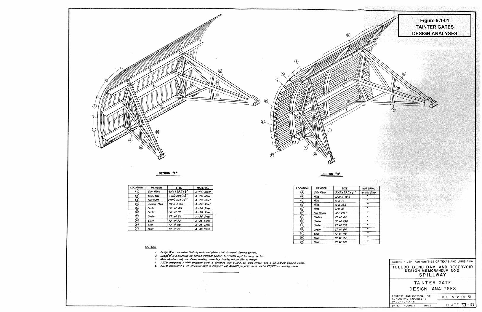
b. Two gate designs were originally considered by Forrest & Cotton in
1962, designated Design “A” and Design “B”. These are shown on Figure 9.1-1. Design “A” was selected for construction.
9.1.2 Component Materials
a. Material properties consist of the following:
Vertical ribs ASTM A441 Steel Skin plates ASTM A441 Steel Girders ASTM A36 Steel Struts ASTM A36 Steel
b. Location and sizes of the above components are shown under the
relevant isometric view on Figure 9.1-1
c. Trunnion Material Properties.
Trunnion Hub Forged Steel Class C Bushing Bronze Alloy ASTM B22 Alloy ‘E’ Trunnion Pin Forged Steel A237, Class ‘B’ Bearing Ring Bronze Alloy ASTM B22 Alloy ‘E’ Thrust Ring Zinc ASTM B69, Type III Trunnion Yoke Steel ASTM A36 Pin Cover Plate Steel ASTM A36 Box Girder Steel ASTM A36
Rev. 0 Page 9-1 12/31/2004
Toledo Bend Project - STI Section 9 Spillway Gates
d. Friction Properties. The friction properties of the trunnion are not indicated in the available documents prepared by Forrest & Cotton. However, Brown & Root contacted the Lubrite Company by phone in 1998, and were told that the trunnions are permanently lubricated and the coefficient of friction could be in the range of 0.07 to 0.15.
Rev. 0 Page 9-2 12/31/2004
Toledo Bend Project - STI Section 9 Spillway Gates
9.2 SUMMARY OF STRESS ANALYSIS COMPUTATIONS 9.2.1 Stress Analysis
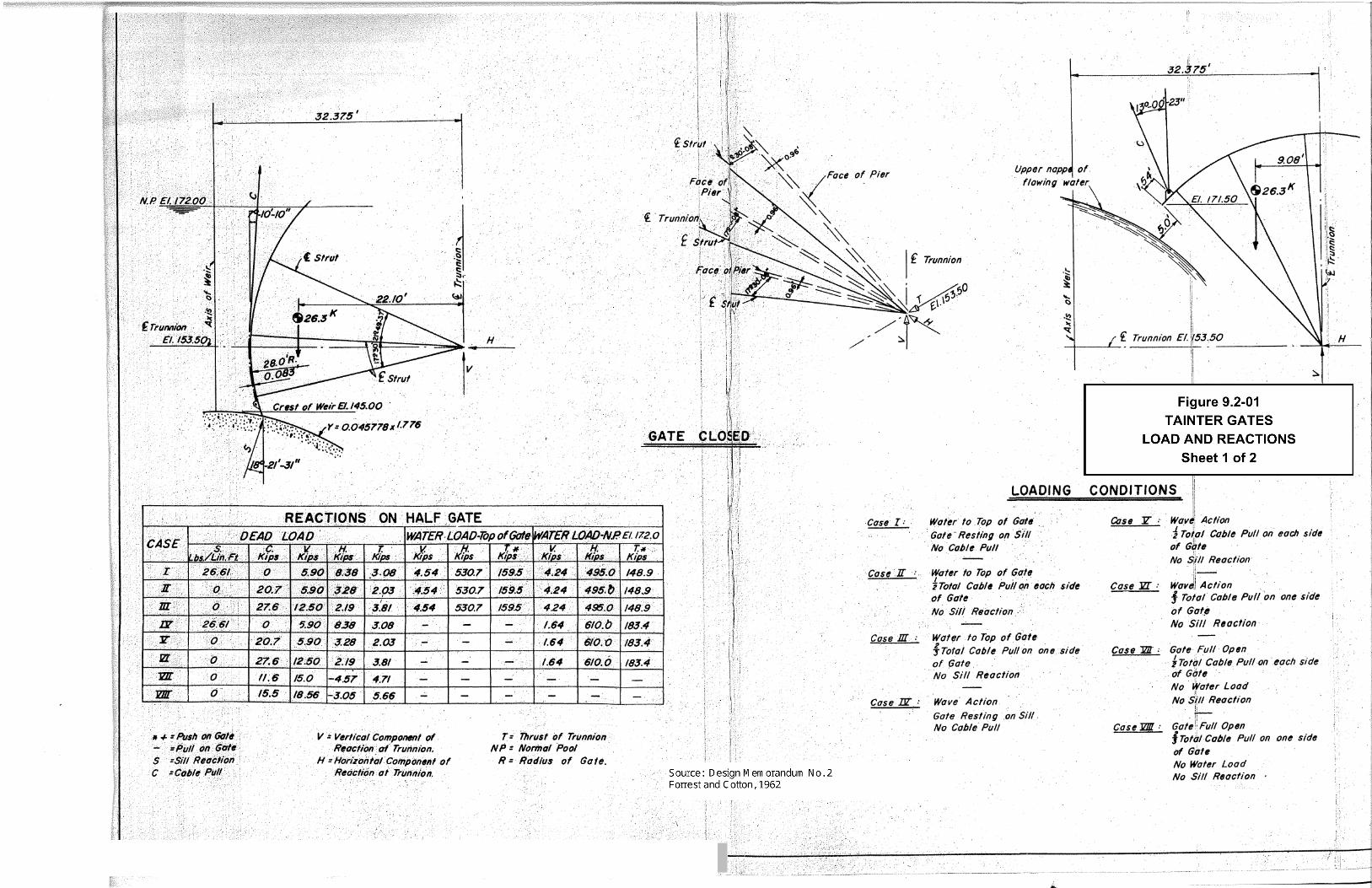
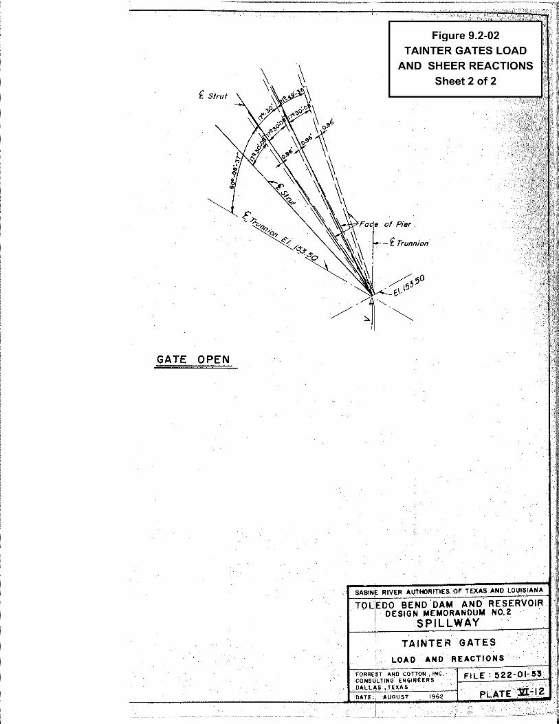
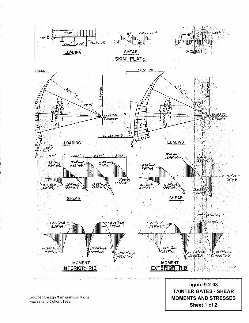
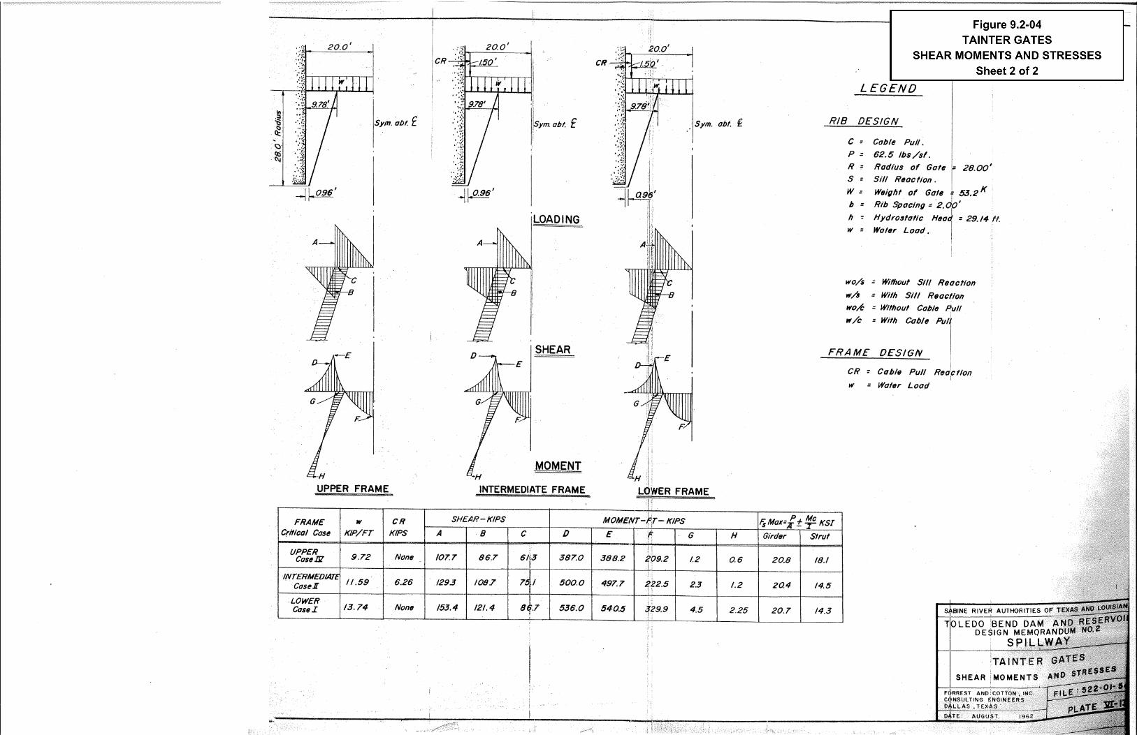
The stress analysis conducted by Forrest & Cotton in 1962 is summarized on Figure 9.2-1 which includes eight design load cases on the gates. Critical stresses and bending moments for the vertical ribs are shown on Figure 9.2-2. Further details of the calculations are not available.
9.2.2 Effect of Trunnion Friction on Struts. In order to assess the effect of trunnion friction on the stresses within the struts, a STAAD III space frame analysis was performed by Brown & Root in 1998. Conservative assumptions were used for the coefficient of friction (0.15). The result of this analysis showed that the middle struts were marginally overstressed at 1.1%, which was judged to be within acceptable limits.
Rev. 0 Page 9-3 12/31/2004
Toledo Bend Project - STI Section 9 Spillway Gates
9.3 TRUNNION LUBRICATION PROCEDURE AND SCHEDULE
The trunnion bushing is a Lubrite self-lubricating bushing. According to the manufacturer, the bronze bushing is impregnated with graphite and will never need lubricating. The trunnion anchor covers are welded closed. To date, an inspection of the trunnion anchor rods has never been conducted.
Rev. 0 Page 9-4 12/31/2004
Toledo Bend Project - STI Section 9 Spillway Gates
9.4 SUMMARY OF GATE HOIST MOTOR LOAD TESTS
To date, no gate hoist motor test data has been collected or recorded on a regular basis. The gates are tested at least annually, raised up to one foot each and then lowered. During the 1998 FERC Part 12D Safety Inspection Report, the motors were found to be drawing more amperage than their rating recommended. Investigations regarding the high amperage draw on the spillway lifting machinery motors should continue and remedial action taken if appropriate. In 2004, this was investigated by Etheredge Electric from Shreveport, Louisiana and a report with recommendations is pending. Their initial investigation, according to Mike Rankin at TBPJO, state that it appears the initial high amperage readings were a result of reading both the motor and brake amperage together. Isolated readings of the motor amperage draw need to be collected to determine if there is a real problem. The independent consultant has not seen an official report, or made independent readings to evaluate these statements. The PFMA Report, of 2005, recommends an extra back-up motor be available on-site for emergency replacement if needed. This was also recommended at the discovery of the motor overloading.
Rev. 0 Page 9-5 12/31/2004
Toledo Bend Project - STI Section 9 Spillway Gates
9.5 SPILLWAY GATE DETAILED INSPECTION REPORTS
NOTE: The following paragraphs contain extracts from prior inspection reports pertaining to tainter gates Photographs referenced in that text are not included in this report.
9.5.1 June 1974 FERC Part 12D Inspection Report
9.5.2 S
9.5.3 J
Rev. 0 12/31/200
4-05. It was noted that some leakage was occurring at all the tainter gates in the spillway (photograph 3) with the greatest amount flowing from gates 2, 4, 5 and 7. The leakage in every case was found at the bottom seal near the corner ofthe gate and was not considered to be excessive or serious.
eptember 1979 FERC Part 12D Inspection Report
3-06. It was noted that portions of the spillway gate hoist equipment required painting and lubrication. It is proposed to establish a program for servicing andmaintaining this equipment on a periodic basis.3-07. A study is planned to determine the feasibility of double circuiting the spillway gate hoists.
une 1985 FERC Part 12D Inspection Report
2.7 Spillway Gates & Machinery
The spillway gates were inspected for corrosion, and evidence of maintenance and leaks around the seals on the sides and bottom of gates. The stoplogs were inspected for corrosion, evidence of stress, damage, or any unusual condition. The lifting machinery was inspected for evidence of maintenance, corrosion, andgeneral condition. The spillway gates, stoplogs, and lifting machinery appear to be in good condition with no evidence of problems. The leakage from the spillway gates is minimal. The gates, stoplogs, and machinery have been painted in the recent past, as evidenced by photographs #32, #33, #34, and #35.
Page 9-6 4
Toledo Bend Project - STI Section 9 Spillway Gates
9.5.4 August 1988 FERC Part 12D Inspection Report
2.7 Spillway Gates & Machinery
The spillway gates were inspected for corrosion, and evidence of maintenance and leaks around the seals on the sides and bottom of gates. The stoplogs were inspected for corrosion, evidence of stress, damage, or any unusual condition. The lifting machinery was inspected for evidence of maintenance, corrosion, and general condition. The spillway gates, stoplogs, and lifting machinery appear to be in good condition but there is evidence of corrosion beginning to appear as seen in photograph #57, #58 and #61. This is an unexpected happening because it is understood that the gates and machinery were painted in 1984. There has been a definite deterioration since the 1985 inspection.
One spillway gate was exercised during the inspection. The discharge is shown in photograph #59. The leakage from the spillway gates is minimal.
6.2.5 Spillway Gates - Corrosion is evident at certain limited areas of the gates and lifting machinery. The gates were painted in the not to distant past. Touchup painting of areas evidencing corrosion could be “touchup painted” to delay the date when full painting will be repaired. No completion date is assigned to this recommended action. Delay will result in more “touchup” work being required.
9.5.5 September 1993 FERC Part 12D Inspection Report
6. Spillway Gates and Machinery
At the time of the inspection the spillway gates and machinery were being painted. In the painting operation, every gate is raised to the maximum open position to facilitate surface preparation and painting.
The spillway gates were inspected for corrosion and evidence of maintenance and leaks around the seals on the sides and bottom of gates. The stop logs were inspected for corrosion, evidence of stress, damage, or any unusual condition. The lifting machinery was inspected for evidence of maintenance, corrosion, and general condition. Photographs #72 through #80 show the gates and equipment.
One spillway gate was exercised during the inspection and the machinery found to be performing properly. Standby power located in the right abutment transition section is automatically started weekly and shows to be in good operating condition.
Rev. 0 Page 9-7 12/31/2004
Toledo Bend Project - STI Section 9 Spillway Gates
9.5.6 O
Rev. 0 12/31/200
C. Maintenance of Spillway
The gated concrete spillway has eleven steel taintor gates with each gate having an individual electric motor to hoist it. The hoisting equipment, consisting of the electric motor, gear reduces and drum, is located above the gates well above expected PMF water levels. The gates and lifting equipment are now being painted. During the painting process all the gates are being exercised with each gate lifted to the maximum up position by the hoisting equipment. Both the gates and hoisting equipment are maintained by cleaning, painting, lubricating and exercising on an as needed or periodic basis.
E. Adequacy of Operation of Spillway Gates and Standby Power
A trained, experienced and diligent staff with an appreciation and understanding ofthe spillway gate opening consequences is in charge of operating the spillway gates. During flood release, the staff has available an abundant amount of information and refined judgement for opening and closing the spillway gates. The Owner’s actions in past major flood releases demonstrate their capability in operating the spillway gates in the prescribed manner. The standby diesel power generator is adequate for emergency use.
ctober 1998 FERC Part 12D Inspection Report
6. Spillway Gates and Machinery
The condition of the spillway gates and machinery is shown in photographs #65 through #73.
The spillway gates were inspected for corrosion, evidence of maintenance and leaks around the seals on the sides and bottom of the gates. The lifting machinery was inspected for evidence of maintenance and corrosion, and to assess general condition. Photographs #72 and #73 show the gate lifting equipment.
The gates show corrosion stains with a particularly bad example in photograph #68. The gates were painted in 1993 and cathodic protection was added in 1994. The actual corrosion should be minimized by the cathodic protection. Future corrosion will verify the effectiveness of the cathodic protection. Photograph #70 shows corrosion in the top gate arm near the trunnion. This corrosion is caused by standing water in the arm. A drain hole was undoubtedly supplied in the web of the beam but the hole has probably become plugged and now should be cleared. The Authority should continually check all gates and unplug holes to prevent this condition, as shown in photograph #70.
Page 9-8 4
Toledo Bend Project - STI Section 9 Spillway Gates
9.5.7 D
Rev. 0 12/31/200
6. Spillway Gates and Machinery [Continued]
One spillway gate was exercised during the inspection and the machinery was found to be performing properly.
One matter of concern is that the gate motors are drawing more amps and are requiring more power to raise than should be needed. Investigations as to the cause are being made and possible corrective actions are being taken including lubrication of moving parts, adjusting the brakes and the use other meters to check the amps. Results of these measures will indicate if the problem persists. If so theAuthority should take actions deemed necessary to correct the matter.
Standby power located in the right abutment transition section is automatically started weekly and appears to be in good operating condition.
ecember 2004 FERC Part 12D Inspection Report
h. Spillway Gates and Machinery 1) The condition of the spillway gates and machinery is shown in photographs S-130 through S-157. 2) The spillway gates were inspected for corrosion, evidence of needed maintenance, and leaks around the seals on the sides and bottom of the gates. The lifting machinery was inspected for evidence of needed maintenance and corrosion, and to assess general condition. Photographs S-130, S-132, and S-134 show the gate lifting equipment. 3) The gates show corrosion stains with a particularly bad example in photograph S-135. The gates were painted in 1993 and cathodic protection was added in 1994. The cathodic protection seems to have stabilized the corrosion occurring on the upstream side of the gates. However, when the anodes were welded to the gates, the paint buckled on the downstream side which has since corroded at those locations. These spots have been touch up painted. Photograph S-147 shows corrosion in the top gate arm near the trunnion. This corrosion is caused by standing water in the arm. A drain holewas undoubtedly supplied in the web of the beam but the hole has probably become plugged and now should be cleared. It is recommended that all gates be checked regularly and that any plugged drain holes be cleared to prevent corrosion. During the 2004 inspection some minor amount of debris and water were standing in the web of the beams which make up the gate arms and gate stiffeners. This should continue to be watched and corrected as needed. 4) Gate No. 1 was exercised during the inspection and the machinery was found to be performing properly. Photograph S-136 shows one of the lifting arms during operation.
Page 9-9
4
Toledo Bend Project - STI Section 9 Spillway Gates
h. Spillway Gates and Machinery (continued) 5) Gate No. 5 had a rolled J-bulb seal. Replacement at the first opportunity is recommended because the seal will continue to deteriorate and leak. Gate No. 4 has water jetting out of the ogee. The trunnion cover plate was inspected at Buttress No. 11 and found to be welded closed all around. 6) One matter of concern is that gate motors are drawing more amps and are requiring more power than should be needed. Investigations as to the cause are being made and possible corrective actions are being taken including lubrication of moving parts, adjusting the brakes and the use other meters to check the amps. See Section 5.2 for further details. Results of these measures will indicate if the problem persists. If so, the recommendation is for the TBPJO to take actions deemed necessary to correct the condition. 7) A generator for standby power is located in the right abutment transition section and is automatically started weekly. The system appears to be in good operating condition.
Rev. 0 Page 9-10 12/31/2004