stick (smaw) welding tig (gtaw) weldinglock8.ca/wp-content/uploads/2015/10/150st.pdf · processes...
TRANSCRIPT

Visit our website at
www.MillerWelds.com
Processes
Description
TIG (GTAW) Welding
Stick (SMAW) Welding
OM-2242 208 580N
2007−12
Arc Welding Power Source
Maxstar 150 S, STL, And STHWith Auto-Line�
�
And Non-CE Models
ES
PAÑ
OL
FR
AN
ÇA
ISE
NG
LIS
H
File: TIG (GTAW)
Miller Electric manufactures a full lineof welders and welding related equipment.For information on other quality Millerproducts, contact your local Miller distributor to receive the latest fullline catalog or individual specification sheets. To locate your nearestdistributor or service agency call 1-800-4-A-Miller, or visit us atwww.MillerWelds.com on the web.
Thank you and congratulations on choosing Miller. Now you can getthe job done and get it done right. We know you don’t have time to doit any other way.
That’s why when Niels Miller first started building arc welders in 1929,he made sure his products offered long-lasting value and superiorquality. Like you, his customers couldn’t afford anything less. Millerproducts had to be more than the best they could be. They had to be thebest you could buy.
Today, the people that build and sell Miller products continue thetradition. They’re just as committed to providing equipment and servicethat meets the high standards of quality and value established in 1929.
This Owner’s Manual is designed to help you get the most out of yourMiller products. Please take time to read the Safety precautions. Theywill help you protect yourself against potential hazards on the worksite.
We’ve made installation and operation quickand easy. With Miller you can count on yearsof reliable service with proper maintenance.And if for some reason the unit needs repair,there’s a Troubleshooting section that willhelp you figure out what the problem is. Theparts list will then help you to decide theexact part you may need to fix the problem.Warranty and service information for yourparticular model are also provided.
Miller is the first weldingequipment manufacturer inthe U.S.A. to be registered tothe ISO 9001:2000 QualitySystem Standard.
Working as hard as you do− every power source fromMiller is backed by the mosthassle-free warranty in thebusiness.
From Miller to You
Mil_Thank 2005−04
TABLE OF CONTENTS
SECTION 1 − SAFETY PRECAUTIONS - READ BEFORE USING 1 . . . . . . . . . . . . . . . . . . . . . . . . . . . . . . . . . . . 1-1. Symbol Usage 1 . . . . . . . . . . . . . . . . . . . . . . . . . . . . . . . . . . . . . . . . . . . . . . . . . . . . . . . . . . . . . . . . . . . . . . . . 1-2. Arc Welding Hazards 1 . . . . . . . . . . . . . . . . . . . . . . . . . . . . . . . . . . . . . . . . . . . . . . . . . . . . . . . . . . . . . . . . . . 1-3. Additional Symbols For Installation, Operation, And Maintenance 3 . . . . . . . . . . . . . . . . . . . . . . . . . . . . . 1-4. California Proposition 65 Warnings 4 . . . . . . . . . . . . . . . . . . . . . . . . . . . . . . . . . . . . . . . . . . . . . . . . . . . . . . .
1-5. Principal Safety Standards 4 . . . . . . . . . . . . . . . . . . . . . . . . . . . . . . . . . . . . . . . . . . . . . . . . . . . . . . . . . . . . . 1-6. EMF Information 4 . . . . . . . . . . . . . . . . . . . . . . . . . . . . . . . . . . . . . . . . . . . . . . . . . . . . . . . . . . . . . . . . . . . . . .
SECTION 2 − DEFINITIONS 5 . . . . . . . . . . . . . . . . . . . . . . . . . . . . . . . . . . . . . . . . . . . . . . . . . . . . . . . . . . . . . . . . . . . 2-1. Warning Label Definitions 5 . . . . . . . . . . . . . . . . . . . . . . . . . . . . . . . . . . . . . . . . . . . . . . . . . . . . . . . . . . . . . . 2-2. Symbols And Definitions 6 . . . . . . . . . . . . . . . . . . . . . . . . . . . . . . . . . . . . . . . . . . . . . . . . . . . . . . . . . . . . . . .
2-3. WEEE Label (For Products Sold Within The EU) 6 . . . . . . . . . . . . . . . . . . . . . . . . . . . . . . . . . . . . . . . . . . . SECTION 3 − SPECIFICATIONS AND INSTALLATION 7 . . . . . . . . . . . . . . . . . . . . . . . . . . . . . . . . . . . . . . . . . . . .
3-1. Specifications 7 . . . . . . . . . . . . . . . . . . . . . . . . . . . . . . . . . . . . . . . . . . . . . . . . . . . . . . . . . . . . . . . . . . . . . . . . 3-2. Duty Cycle And Overheating 7 . . . . . . . . . . . . . . . . . . . . . . . . . . . . . . . . . . . . . . . . . . . . . . . . . . . . . . . . . . . .
3-3. Volt-Ampere Curves 8 . . . . . . . . . . . . . . . . . . . . . . . . . . . . . . . . . . . . . . . . . . . . . . . . . . . . . . . . . . . . . . . . . . . 3-4. Remote 6 Receptacle Information (STL And STH Models Only) 8 . . . . . . . . . . . . . . . . . . . . . . . . . . . . . . . 3-5. Electrical Service Guide For 230 VAC 9 . . . . . . . . . . . . . . . . . . . . . . . . . . . . . . . . . . . . . . . . . . . . . . . . . . . . 3-7. Selecting A Location, And Connecting Input Power 10 . . . . . . . . . . . . . . . . . . . . . . . . . . . . . . . . . . . . . . . . . 3-8. Connecting 1-Phase Input Power For 230 VAC 11 . . . . . . . . . . . . . . . . . . . . . . . . . . . . . . . . . . . . . . . . . . . .
SECTION 4 − OPERATION 12 . . . . . . . . . . . . . . . . . . . . . . . . . . . . . . . . . . . . . . . . . . . . . . . . . . . . . . . . . . . . . . . . . . . . 4-1. Front Panel Controls And Gas Connection 12 . . . . . . . . . . . . . . . . . . . . . . . . . . . . . . . . . . . . . . . . . . . . . . . . 4-2. Process Selection (STL Model Only) 12 . . . . . . . . . . . . . . . . . . . . . . . . . . . . . . . . . . . . . . . . . . . . . . . . . . . . . 4-3. Process Selection (STH Model Only) 13 . . . . . . . . . . . . . . . . . . . . . . . . . . . . . . . . . . . . . . . . . . . . . . . . . . . . . 4-4. Lift-Arc And TIG Impulse Start Procedures 13 . . . . . . . . . . . . . . . . . . . . . . . . . . . . . . . . . . . . . . . . . . . . . . . .
4-5. Set-Up Procedure For The TIG Process And Restoring Factory Default Settings (STH Model Only) 14 SECTION 5 − MAINTENANCE AND TROUBLESHOOTING 16 . . . . . . . . . . . . . . . . . . . . . . . . . . . . . . . . . . . . . . . .
5-1. Routine Maintenance 16 . . . . . . . . . . . . . . . . . . . . . . . . . . . . . . . . . . . . . . . . . . . . . . . . . . . . . . . . . . . . . . . . . . 5-2. Overload Protection 16 . . . . . . . . . . . . . . . . . . . . . . . . . . . . . . . . . . . . . . . . . . . . . . . . . . . . . . . . . . . . . . . . . . . 5-3. Troubleshooting 17 . . . . . . . . . . . . . . . . . . . . . . . . . . . . . . . . . . . . . . . . . . . . . . . . . . . . . . . . . . . . . . . . . . . . . .
SECTION 6 − ELECTRICAL DIAGRAM 18 . . . . . . . . . . . . . . . . . . . . . . . . . . . . . . . . . . . . . . . . . . . . . . . . . . . . . . . . . . SECTION 7 − PARTS LIST FOR S MODELS 20 . . . . . . . . . . . . . . . . . . . . . . . . . . . . . . . . . . . . . . . . . . . . . . . . . . . . . SECTION 8 − PARTS LIST FOR STL MODELS 22 . . . . . . . . . . . . . . . . . . . . . . . . . . . . . . . . . . . . . . . . . . . . . . . . . . . SECTION 9 − PARTS LIST FOR STH MODELS 24 . . . . . . . . . . . . . . . . . . . . . . . . . . . . . . . . . . . . . . . . . . . . . . . . . . . WARRANTY

EN
GL
ISH
dec_stat_1/07
Declaration of Conformity forEuropean Community (CE) Products
� This information is provided for units with CE certification (see rating label on unit).
Manufacturer: European Contact:Miller Electric Mg. Co. Mr. Danilo Fedolfi,1635 W. Spencer St. Managing DirectorAppleton, WI 54914 USA ITW Welding Products Italy S.r.l.Phone: (920) 734-9821 Via Privata Iseo 6/E
20098 San GiulianoMilanese, ItalyPhone: 39(02)98290-1Fax: 39(02)98290203
European Contact Signature:
Declares that this product: Maxstar � 150 S And STHconforms to the following Directives and Standards:
Directives
Low Voltage Directive: 73/23/EEC
Electromagnetic compatibility Directives: 89/336/EEC, 92/31/EEC
Machinery Directives: 98/37EEC, 91/368/EEC, 92/31/EEC, 133/04, 93/68/EEC
Standards
Arc Welding Equipment − Part 10: Electromagnetic Compatibility (EMC) Requirements. IEC 60974-10 August 2002
Arc Welding Equipment − Part 1: Welding Power Sources. IEC 60974-1 Ed. 3
Degrees of Protection Provided By Enclosures (IP Code): IEC 60529 Ed. 2.1
Insulation Coordination For Equipment Within Low-Voltage Systems:Part 1: Principles, Requirements And Tests. IEC 60664-1 Ed. 1.1
The product technical file is maintained by the responsible Business Unit(s) located at the manufacturing facility.
EN
GL
ISH
OM-2242 Page 1
SECTION 1 − SAFETY PRECAUTIONS - READ BEFORE USINGsom _2007−04
7
Protect yourself and others from injury — read and follow these precautions.
1-1. Symbol Usage
DANGER! − Indicates a hazardous situation which, ifnot avoided, will result in death or serious injury. Thepossible hazards are shown in the adjoining symbolsor explained in the text.
Indicates a hazardous situation which, if not avoided,could result in death or serious injury. The possiblehazards are shown in the adjoining symbols or ex-plained in the text.
NOTICE − Indicates statements not related to personal injury.
� Indicates special instructions.
This group of symbols means Warning! Watch Out! ELECTRICSHOCK, MOVING PARTS, and HOT PARTS hazards. Consult sym-bols and related instructions below for necessary actions to avoid thehazards.
1-2. Arc Welding Hazards
The symbols shown below are used throughout this manualto call attention to and identify possible hazards. When yousee the symbol, watch out, and follow the related instructionsto avoid the hazard. The safety information given below isonly a summary of the more complete safety informationfound in the Safety Standards listed in Section 1-5. Read andfollow all Safety Standards.
Only qualified persons should install, operate, maintain, andrepair this unit.
During operation, keep everybody, especially children, away.
ELECTRIC SHOCK can kill.
Touching live electrical parts can cause fatal shocksor severe burns. The electrode and work circuit iselectrically live whenever the output is on. The inputpower circuit and machine internal circuits are also
live when power is on. In semiautomatic or automatic wire welding, thewire, wire reel, drive roll housing, and all metal parts touching thewelding wire are electrically live. Incorrectly installed or improperlygrounded equipment is a hazard.
� Do not touch live electrical parts.� Wear dry, hole-free insulating gloves and body protection.� Insulate yourself from work and ground using dry insulating mats
or covers big enough to prevent any physical contact with the workor ground.
� Do not use AC output in damp areas, if movement is confined, or ifthere is a danger of falling.
� Use AC output ONLY if required for the welding process.� If AC output is required, use remote output control if present on
unit.� Additional safety precautions are required when any of the follow-
ing electrically hazardous conditions are present: in damplocations or while wearing wet clothing; on metal structures suchas floors, gratings, or scaffolds; when in cramped positions suchas sitting, kneeling, or lying; or when there is a high risk of unavoid-able or accidental contact with the workpiece or ground. For theseconditions, use the following equipment in order presented: 1) asemiautomatic DC constant voltage (wire) welder, 2) a DC manual(stick) welder, or 3) an AC welder with reduced open-circuit volt-age. In most situations, use of a DC, constant voltage wire welderis recommended. And, do not work alone!
� Disconnect input power or stop engine before installing orservicing this equipment. Lockout/tagout input power according toOSHA 29 CFR 1910.147 (see Safety Standards).
� Properly install and ground this equipment according to itsOwner’s Manual and national, state, and local codes.
� Always verify the supply ground − check and be sure that inputpower cord ground wire is properly connected to ground terminal indisconnect box or that cord plug is connected to a properlygrounded receptacle outlet.
� When making input connections, attach proper grounding conduc-tor first − double-check connections.
� Keep cords dry, free of oil and grease, and protected from hot metaland sparks.
� Frequently inspect input power cord for damage or bare wiring −replace cord immediately if damaged − bare wiring can kill.
� Turn off all equipment when not in use.
� Do not use worn, damaged, undersized, or poorly spliced cables.
� Do not drape cables over your body.
� If earth grounding of the workpiece is required, ground it directlywith a separate cable.
� Do not touch electrode if you are in contact with the work, ground,or another electrode from a different machine.
� Do not touch electrode holders connected to two welding ma-chines at the same time since double open-circuit voltage will bepresent.
� Use only well-maintained equipment. Repair or replace damagedparts at once. Maintain unit according to manual.
� Wear a safety harness if working above floor level.
� Keep all panels and covers securely in place.
� Clamp work cable with good metal-to-metal contact to workpieceor worktable as near the weld as practical.
� Insulate work clamp when not connected to workpiece to preventcontact with any metal object.
� Do not connect more than one electrode or work cable to anysingle weld output terminal.
SIGNIFICANT DC VOLTAGE exists in inverter-typewelding power sources after removal of inputpower.� Turn Off inverter, disconnect input power, and discharge input
capacitors according to instructions in Maintenance Sectionbefore touching any parts.
HOT PARTS can cause severe burns.
� Do not touch hot parts bare handed.� Allow cooling period before working on gun or
torch.� To handle hot parts, use proper tools and/or
wear heavy, insulated welding gloves andclothing to prevent burns.
OM-2242 Page 2
Welding produces fumes and gases. Breathingthese fumes and gases can be hazardous to yourhealth.
FUMES AND GASES can be hazardous.
� Keep your head out of the fumes. Do not breathe the fumes.
� If inside, ventilate the area and/or use local forced ventilation at thearc to remove welding fumes and gases.
� If ventilation is poor, wear an approved air-supplied respirator.
� Read and understand the Material Safety Data Sheets (MSDSs)and the manufacturer’s instructions for metals, consumables,coatings, cleaners, and degreasers.
� Work in a confined space only if it is well ventilated, or whilewearing an air-supplied respirator. Always have a trained watch-person nearby. Welding fumes and gases can displace air andlower the oxygen level causing injury or death. Be sure the breath-ing air is safe.
� Do not weld in locations near degreasing, cleaning, or spraying op-erations. The heat and rays of the arc can react with vapors to formhighly toxic and irritating gases.
� Do not weld on coated metals, such as galvanized, lead, orcadmium plated steel, unless the coating is removed from the weldarea, the area is well ventilated, and while wearing an air-suppliedrespirator. The coatings and any metals containing these elementscan give off toxic fumes if welded.
Arc rays from the welding process produce intensevisible and invisible (ultraviolet and infrared) raysthat can burn eyes and skin. Sparks fly off from theweld.
ARC RAYS can burn eyes and skin.
� Wear an approved welding helmet fitted with a proper shade of fil-ter lenses to protect your face and eyes when welding or watching(see ANSI Z49.1 and Z87.1 listed in Safety Standards).
� Wear approved safety glasses with side shields under yourhelmet.
� Use protective screens or barriers to protect others from flash,glare and sparks; warn others not to watch the arc.
� Wear protective clothing made from durable, flame-resistant mate-rial (leather, heavy cotton, or wool) and foot protection.
Welding on closed containers, such as tanks,drums, or pipes, can cause them to blow up. Sparkscan fly off from the welding arc. The flying sparks, hotworkpiece, and hot equipment can cause fires and
burns. Accidental contact of electrode to metal objects can causesparks, explosion, overheating, or fire. Check and be sure the area issafe before doing any welding.
WELDING can cause fire or explosion.
� Remove all flammables within 35 ft (10.7 m) of the welding arc. Ifthis is not possible, tightly cover them with approved covers.
� Do not weld where flying sparks can strike flammable material.
� Protect yourself and others from flying sparks and hot metal.
� Be alert that welding sparks and hot materials from welding caneasily go through small cracks and openings to adjacent areas.
� Watch for fire, and keep a fire extinguisher nearby.
� Be aware that welding on a ceiling, floor, bulkhead, or partition cancause fire on the hidden side.
� Do not weld on closed containers such as tanks, drums, or pipes,unless they are properly prepared according to AWS F4.1 (seeSafety Standards).
� Do not weld where the atmosphere may contain flammable dust,gas, or liquid vapors (such as gasoline).
� Connect work cable to the work as close to the welding area aspractical to prevent welding current from traveling long, possiblyunknown paths and causing electric shock, sparks, and firehazards.
� Do not use welder to thaw frozen pipes.� Remove stick electrode from holder or cut off welding wire at
contact tip when not in use.� Wear oil-free protective garments such as leather gloves, heavy
shirt, cuffless trousers, high shoes, and a cap.� Remove any combustibles, such as a butane lighter or matches,
from your person before doing any welding.� After completion of work, inspect area to ensure it is free of sparks,
glowing embers, and flames.� Use only correct fuses or circuit breakers. Do not oversize or by-
pass them.� Follow requirements in OSHA 1910.252 (a) (2) (iv) and NFPA 51B
for hot work and have a fire watcher and extinguisher nearby.
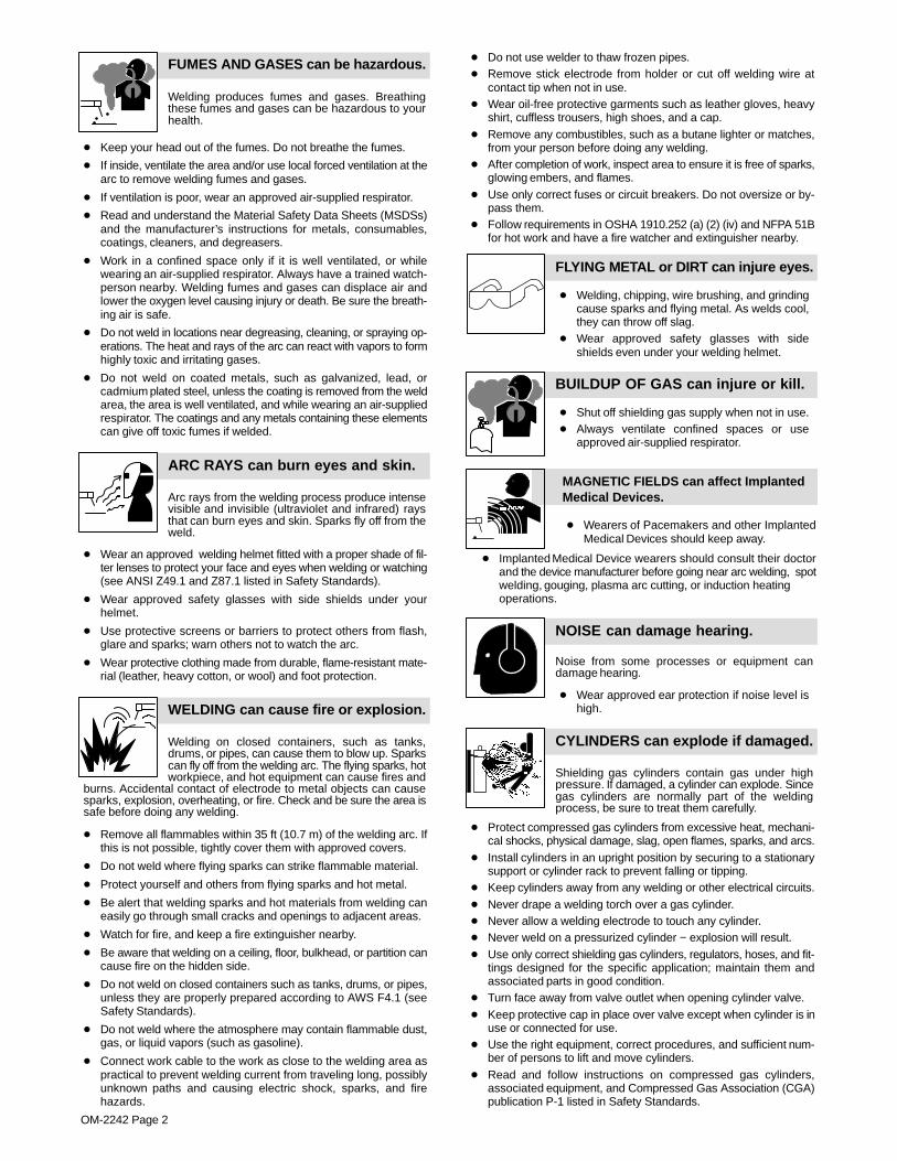
FLYING METAL or DIRT can injure eyes.
� Welding, chipping, wire brushing, and grindingcause sparks and flying metal. As welds cool,they can throw off slag.
� Wear approved safety glasses with sideshields even under your welding helmet.
BUILDUP OF GAS can injure or kill.
� Shut off shielding gas supply when not in use.� Always ventilate confined spaces or use
approved air-supplied respirator.
MAGNETIC FIELDS can affect ImplantedMedical Devices.
� Wearers of Pacemakers and other ImplantedMedical Devices should keep away.
� Implanted Medical Device wearers should consult their doctorand the device manufacturer before going near arc welding, spotwelding, gouging, plasma arc cutting, or induction heatingoperations.
NOISE can damage hearing.
Noise from some processes or equipment candamage hearing.
� Wear approved ear protection if noise level ishigh.
Shielding gas cylinders contain gas under highpressure. If damaged, a cylinder can explode. Sincegas cylinders are normally part of the weldingprocess, be sure to treat them carefully.
CYLINDERS can explode if damaged.
� Protect compressed gas cylinders from excessive heat, mechani-cal shocks, physical damage, slag, open flames, sparks, and arcs.
� Install cylinders in an upright position by securing to a stationarysupport or cylinder rack to prevent falling or tipping.
� Keep cylinders away from any welding or other electrical circuits.� Never drape a welding torch over a gas cylinder.� Never allow a welding electrode to touch any cylinder.� Never weld on a pressurized cylinder − explosion will result.� Use only correct shielding gas cylinders, regulators, hoses, and fit-
tings designed for the specific application; maintain them andassociated parts in good condition.
� Turn face away from valve outlet when opening cylinder valve.� Keep protective cap in place over valve except when cylinder is in
use or connected for use.� Use the right equipment, correct procedures, and sufficient num-
ber of persons to lift and move cylinders.� Read and follow instructions on compressed gas cylinders,
associated equipment, and Compressed Gas Association (CGA)publication P-1 listed in Safety Standards.
EN
GL
ISH
OM-2242 Page 3
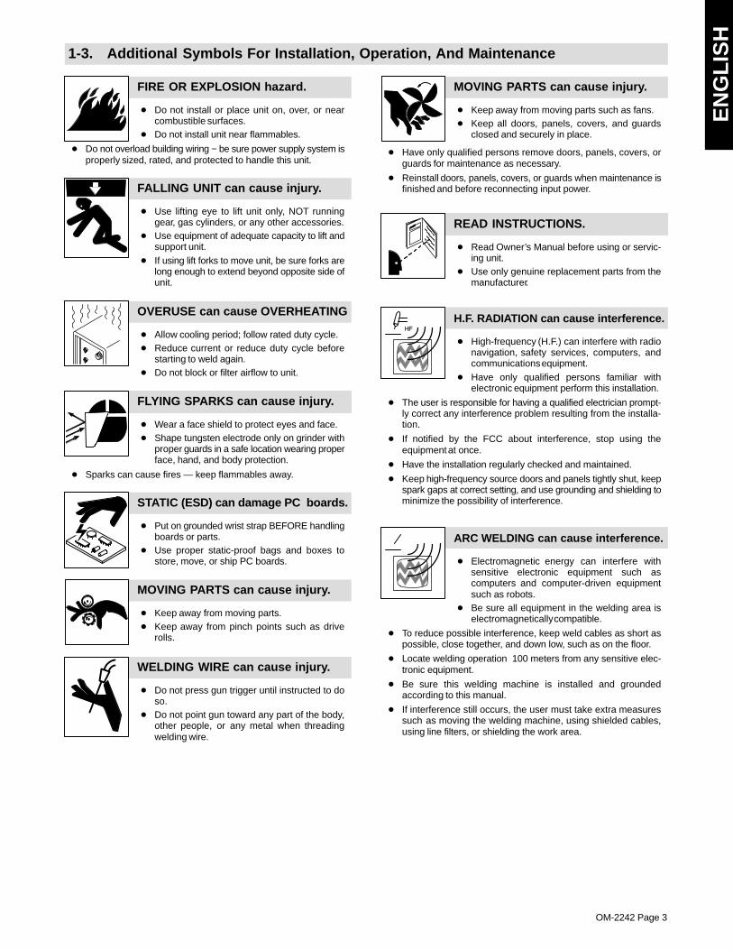
1-3. Additional Symbols For Installation, Operation, And Maintenance
FIRE OR EXPLOSION hazard.
� Do not install or place unit on, over, or nearcombustible surfaces.
� Do not install unit near flammables.
� Do not overload building wiring − be sure power supply system isproperly sized, rated, and protected to handle this unit.
FALLING UNIT can cause injury.
� Use lifting eye to lift unit only, NOT runninggear, gas cylinders, or any other accessories.
� Use equipment of adequate capacity to lift andsupport unit.
� If using lift forks to move unit, be sure forks arelong enough to extend beyond opposite side ofunit.
OVERUSE can cause OVERHEATING
� Allow cooling period; follow rated duty cycle.� Reduce current or reduce duty cycle before
starting to weld again.� Do not block or filter airflow to unit.
FLYING SPARKS can cause injury.
� Wear a face shield to protect eyes and face.� Shape tungsten electrode only on grinder with
proper guards in a safe location wearing properface, hand, and body protection.
� Sparks can cause fires — keep flammables away.
STATIC (ESD) can damage PC boards.
� Put on grounded wrist strap BEFORE handlingboards or parts.
� Use proper static-proof bags and boxes tostore, move, or ship PC boards.
MOVING PARTS can cause injury.
� Keep away from moving parts.� Keep away from pinch points such as drive
rolls.
WELDING WIRE can cause injury.
� Do not press gun trigger until instructed to doso.
� Do not point gun toward any part of the body,other people, or any metal when threadingwelding wire.
MOVING PARTS can cause injury.
� Keep away from moving parts such as fans.� Keep all doors, panels, covers, and guards
closed and securely in place.
� Have only qualified persons remove doors, panels, covers, orguards for maintenance as necessary.
� Reinstall doors, panels, covers, or guards when maintenance isfinished and before reconnecting input power.
READ INSTRUCTIONS.
� Read Owner’s Manual before using or servic-ing unit.
� Use only genuine replacement parts from themanufacturer.
H.F. RADIATION can cause interference.
� High-frequency (H.F.) can interfere with radionavigation, safety services, computers, andcommunications equipment.
� Have only qualified persons familiar withelectronic equipment perform this installation.
� The user is responsible for having a qualified electrician prompt-ly correct any interference problem resulting from the installa-tion.
� If notified by the FCC about interference, stop using theequipment at once.
� Have the installation regularly checked and maintained.
� Keep high-frequency source doors and panels tightly shut, keepspark gaps at correct setting, and use grounding and shielding tominimize the possibility of interference.
ARC WELDING can cause interference.
� Electromagnetic energy can interfere withsensitive electronic equipment such ascomputers and computer-driven equipmentsuch as robots.
� Be sure all equipment in the welding area iselectromagnetically compatible.
� To reduce possible interference, keep weld cables as short aspossible, close together, and down low, such as on the floor.
� Locate welding operation 100 meters from any sensitive elec-tronic equipment.
� Be sure this welding machine is installed and groundedaccording to this manual.
� If interference still occurs, the user must take extra measuressuch as moving the welding machine, using shielded cables,using line filters, or shielding the work area.
OM-2242 Page 4
1-4. California Proposition 65 Warnings
Welding or cutting equipment produces fumes or gaseswhich contain chemicals known to the State of California tocause birth defects and, in some cases, cancer. (CaliforniaHealth & Safety Code Section 25249.5 et seq.)
Battery posts, terminals and related accessories contain leadand lead compounds, chemicals known to the State ofCalifornia to cause cancer and birth defects or otherreproductive harm. Wash hands after handling.
For Gasoline Engines:
Engine exhaust contains chemicals known to the State ofCalifornia to cause cancer, birth defects, or other reproduc-tive harm.
For Diesel Engines:
Diesel engine exhaust and some of its constituents areknown to the State of California to cause cancer, birthdefects, and other reproductive harm.
1-5. Principal Safety Standards
Safety in Welding, Cutting, and Allied Processes, ANSI Standard Z49.1,from Global Engineering Documents (phone: 1-877-413-5184, website:www.global.ihs.com).
Recommended Safe Practices for the Preparation for Welding and Cut-ting of Containers and Piping, American Welding Society StandardAWS F4.1, from Global Engineering Documents (phone:1-877-413-5184, website: www.global.ihs.com).
National Electrical Code, NFPA Standard 70, from National Fire Protec-tion Association, P.O. Box 9101, Quincy, MA 02269-9101 (phone:617-770-3000, website: www.nfpa.org and www. sparky.org).
Safe Handling of Compressed Gases in Cylinders, CGA Pamphlet P-1,from Compressed Gas Association, 4221 Walney Road, 5th Floor,Chantilly, VA 20151 (phone: 703-788-2700, website:www.cganet.com).
Code for Safety in Welding and Cutting, CSA Standard W117.2, fromCanadian Standards Association, Standards Sales, 5060 Mississauga,
Ontario, Canada L4W 5NS (phone: 800-463-6727 or in Toronto416-747-4044, website: www.csa-international.org).Safe Practice For Occupational And Educational Eye And Face Protec-tion, ANSI Standard Z87.1, from American National Standards Institute,25 West 43rd Street, New York, NY 10036–8002 (phone:212-642-4900, website: www.ansi.org).Standard for Fire Prevention During Welding, Cutting, and Other HotWork, NFPA Standard 51B, from National Fire Protection Association,P.O. Box 9101, Quincy, MA 02269-9101 (phone: 617-770-3000, web-site: www.nfpa.org.OSHA, Occupational Safety and Health Standards for General Indus-try, Title 29, Code of Federal Regulations (CFR), Part 1910, Subpart Q,and Part 1926, Subpart J, from U.S. Government Printing Office, Super-intendent of Documents, P.O. Box 371954, Pittsburgh, PA 15250-7954(phone: 1-866-512-1800) (there are 10 Regional Offices—phone forRegion 5, Chicago, is 312-353-2220, website: www.osha.gov).
1-6. EMF Information
Considerations About Welding And The Effects Of Low FrequencyElectric And Magnetic Fields
Welding current, as it flows through welding cables, will cause electro-magnetic fields. There has been and still is some concern about suchfields. However, after examining more than 500 studies spanning 17years of research, a special blue ribbon committee of the NationalResearch Council concluded that: “The body of evidence, in thecommittee’s judgment, has not demonstrated that exposure to power-frequency electric and magnetic fields is a human-health hazard.”However, studies are still going forth and evidence continues to beexamined. Until the final conclusions of the research are reached, youmay wish to minimize your exposure to electromagnetic fields whenwelding or cutting.
To reduce magnetic fields in the workplace, use the followingprocedures:
1. Keep cables close together by twisting or taping them, or using acable cover.
2. Arrange cables to one side and away from the operator.
3. Do not coil or drape cables around your body.
4. Keep welding power source and cables as far away from opera-tor as practical.
5. Connect work clamp to workpiece as close to the weld as possi-ble.
About Implanted Medical Devices:Implanted Medical Device wearers should consult their doctor and thedevice manufacturer before performing or going near arc welding, spotwelding, gouging, plasma arc cutting, or induction heating operations.If cleared by your doctor, then following the above procedures is recom-mended.
EN
GL
ISH
OM-2242 Page 5
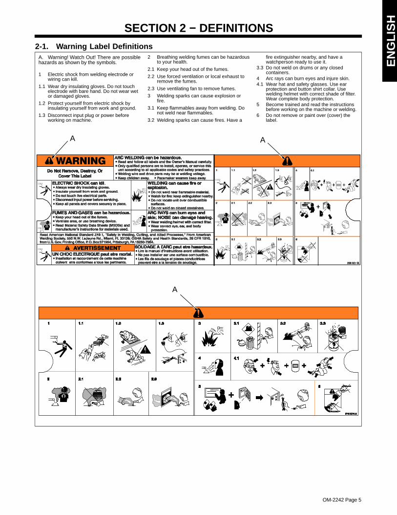
SECTION 2 − DEFINITIONS2-1. Warning Label Definitions
A. Warning! Watch Out! There are possiblehazards as shown by the symbols.
1 Electric shock from welding electrode orwiring can kill.
1.1 Wear dry insulating gloves. Do not touchelectrode with bare hand. Do not wear wetor damaged gloves.
1.2 Protect yourself from electric shock byinsulating yourself from work and ground.
1.3 Disconnect input plug or power beforeworking on machine.
2 Breathing welding fumes can be hazardousto your health.
2.1 Keep your head out of the fumes.
2.2 Use forced ventilation or local exhaust toremove the fumes.
2.3 Use ventilating fan to remove fumes.
3 Welding sparks can cause explosion orfire.
3.1 Keep flammables away from welding. Donot weld near flammables.
3.2 Welding sparks can cause fires. Have a
fire extinguisher nearby, and have awatchperson ready to use it.
3.3 Do not weld on drums or any closedcontainers.
4 Arc rays can burn eyes and injure skin.4.1 Wear hat and safety glasses. Use ear
protection and button shirt collar. Usewelding helmet with correct shade of filter.Wear complete body protection.
5 Become trained and read the instructionsbefore working on the machine or welding.
6 Do not remove or paint over (cover) thelabel.
AA
A
OM-2242 Page 6
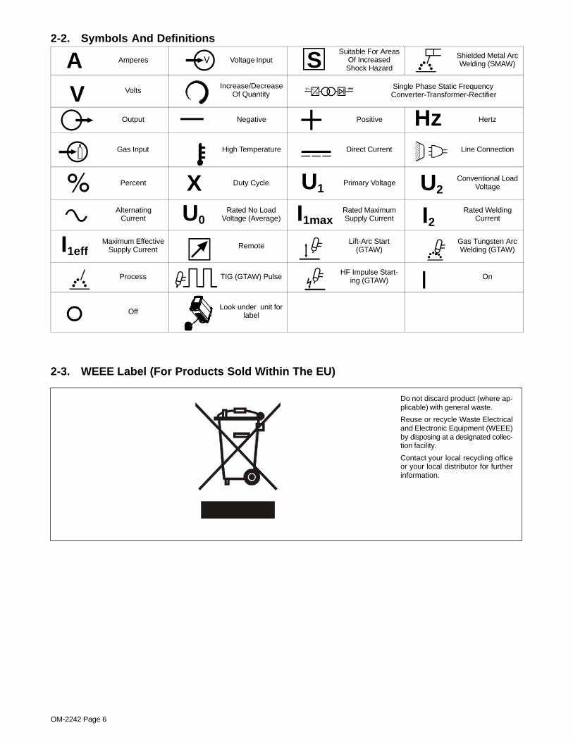
2-2. Symbols And Definitions
A Amperes Voltage Input SSuitable For Areas
Of IncreasedShock Hazard
Shielded Metal ArcWelding (SMAW)
V VoltsIncrease/Decrease
Of QuantitySingle Phase Static FrequencyConverter-Transformer-Rectifier
Output Negative Positive Hz Hertz
Gas Input High Temperature Direct Current Line Connection
Percent X Duty Cycle U1Primary Voltage U2
Conventional LoadVoltage
AlternatingCurrent U0
Rated No LoadVoltage (Average) I1max
Rated MaximumSupply Current I2
Rated WeldingCurrent
I1effMaximum Effective
Supply Current RemoteLift-Arc Start
(GTAW)Gas Tungsten ArcWelding (GTAW)
Process TIG (GTAW) PulseHF Impulse Start-
ing (GTAW) On
OffLook under unit for
label
2-3. WEEE Label (For Products Sold Within The EU)
Do not discard product (where ap-plicable) with general waste.
Reuse or recycle Waste Electricaland Electronic Equipment (WEEE)by disposing at a designated collec-tion facility.
Contact your local recycling officeor your local distributor for furtherinformation.
EN
GL
ISH
OM-2242 Page 7
SECTION 3 − SPECIFICATIONS AND INSTALLATION
3-1. Specifications
Input Power
Single-Phase
AC
Rated Welding
Output
WeldingAmperage
Range
MaxOCVDC
Amperes In-put At RatedLoad Output,
50/60Hz,Single-Phase
KVA @DutyCycle
KW Dimensions Weight
115 Volts StickAnd TIG
15A
70A @ 22.8 Volts DC,100% Duty Cycle 20 − 100A
90V
*12-1617.4 2.0 1.9
115 Volts Stick
70A @ 22.8 Volts DC,100% Duty Cycle
20 − 100A90V
17.4 2.0 1.9 115 Volts Stick
20A 100A @ 24.0 Volts DC,35% Duty Cycle
20 − 100A90V
*12-1626.4 3.0 3.0
115 Volts TIG
100A @ 14.0 Volts DC,100% Duty Cycle
5 − 150A90V
18.4 2.1 2.1H: 9 in (229 mm)
13.7 lb 115 Volts TIG
20A 150A @ 16.0 Volts DC,30% Duty Cycle
5 − 150A90V
*12-1628.0 3.4 3.1
H: 9 in (229 mm)
W: 5.5 in (140 mm)
L: 13.25 in (337 mm)
13.7 lb(6.2 kg)
230 Volts Stick
100A @ 24 Volts DC,100% Duty Cycle
20 − 150A90V
13.1 3.0 2.8
L: 13.25 in (337 mm)
230 Volts Stick150A @ 26.0 Volts DC,
30% Duty Cycle
20 − 150A90V
*12-1621.6 4.9 4.7
230 Volts TIG
100A @ 14.0 Volts DC,100% Duty Cycle
5 − 150A90V
8.3 2.0 1.9
230 Volts TIG150A @ 16.0 Volts DC,
30% Duty Cycle
5 − 150A90V
*12-1614.2 3.2 3.1
*Sense Voltage For Stick And TIG Lift Arc�
3-2. Duty Cycle And Overheating
208 608-D
Duty Cycle is percentage of 10 min-utes that unit can weld at rated loadwithout overheating.
If unit overheats, output stops, theOvertemperature Light comes On,and the cooling fan runs. Wait fif-teen minutes for unit to cool. Re-duce amperage or duty cycle be-fore starting to weld again.
NOTICE − Exceeding duty cyclecan damage unit and void warranty.
0
50
100
150
200
250
10 100
STICK(230V)
TIG/STICK(115V 15A)
STICK(115V 20A)
% DUTY CYCLE
OUTPUT AMPERES
50
TIG (115V 20A& 230V)
OM-2242 Page 8
3-3. Volt-Ampere CurvesVolt-ampere curves show minimum and maximum voltage and amperage output capabilitiesof welding power source. Curves of other settings fall between curves shown.
208 604-B
TIG/Stick Max
TIG Min
Stick Min
Amperes
Vol
ts
115 VAC Input 230 VAC Input
Amperes
Vol
ts TIG/Stick Max
Stick Min
TIG Min
100
80
60
40
20
00 50 100 150 200
100
80
60
40
20
00 50 100 150 200
3-4. Remote 6 Receptacle Information (STL And STH Models Only)
6 Socket Socket Information
15 VOLTS DC1 Contactor control +13.8 volts DC.
15 VOLTS DC
OUTPUTCONTACTOR
2 Contact closure to 1 completes contactor controlcircuit and enables output when Lift-Arc TIG re-mote is selected.
REMOTE
3 Output to remote control; +10 volts DC output toremote control.
REMOTEOUTPUT
CONTROL4 0 to +10 volts DC input command signal from
remote control.
5 Remote control circuit common.
CHASSIS 6 Chassis common.
EN
GL
ISH
OM-2242 Page 9
3-5. Electrical Service Guide For 230 VACNOTICE − INCORRECT INPUT POWER can damage this welding power source. This welding power source requires a CONTINUOUS supply of60 Hz (±10%) power at ±10% of rated input voltage. Phase to ground voltage shall not exceed +10% of rated input voltage. Do not use a generatorwith automatic idle device (that idles engine when no load is sensed) to supply input power to this welding power source.
� Actual input voltage should not exceed ± 10% of indicated required input voltage. If actual input voltage is outside of this range, output may notbe available.
Failure to follow these electrical service guide recommendations could create an electric shock or fire hazard. These recommenda-tions are for a dedicated branch circuit sized for the rated output and duty cycle of the welding power source.
60 HzSinglePhase
Input Voltage 230
Input Amperes At Rated Output 13.1
Max Recommended Standard Fuse Rating In Amperes
Circuit Breaker 1, Time-Delay 2 15
Normal Operating 3 20
Min Input Conductor Size In AWG 4 14
Max Recommended Input Conductor Length In Feet (Meters)91
(28)
Min Grounding Conductor Size In AWG 4 14
Reference: 2005 National Electrical Code (NEC) (including article 630)1 Choose a circuit breaker with time-current curves comparable to a Time Delay Fuse.
2 “Time-Delay” fuses are UL class “RK5” .3 “Normal Operating” (general purpose - no intentional delay) fuses are UL class “K5” (up to and including 60 amp), and UL class “H” ( 65 amp and
above).4 Conductor data in this section specifies conductor size (excluding flexible cord or cable) between the panelboard and the equipment per NEC Table
310.16. If a flexible cord or cable is used, minimum conductor size may increase. See NEC Table 400.5(A) for flexible cord and cable requirements.
3-6. Selecting Extension Cord (Use Shortest Cord Possible)
Single Phase ACConductor Size − AWG [mm2]*
Single Phase AC
Input Voltage4 [21.2] 6 [13.3] 8 [8.4] 10 [5.3] 12 [3.3]
Input Voltage
Maximum Allowable Cord Length in ft (m)
115 160 (49) 107 (33) 71 (22) 47 (14) 29 (9)
230 471 (144) 321 (98) 215 (66) 146 (45) 90 (27)
*Conductor size is based on maximum 3% voltage drop
OM-2242 Page 10
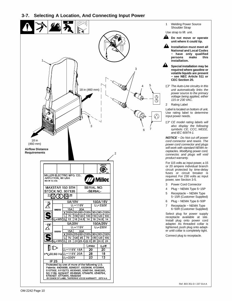
1 Welding Power SourceShoulder Strap
Use strap to lift unit.
! Do not move or operateunit where it could tip.
! Installation must meet allNational and Local Codes− have only qualifiedpersons make thisinstallation.
! Special installation may berequired where gasoline orvolatile liquids are present− see NEC Article 511 orCEC Section 20.
� The Auto-Line circuitry in thisunit automatically links thepower source to the primaryvoltage being applied, either115 or 230 VAC.
2 Rating Label
Label is located on bottom of unit.Use rating label to determineinput power needs.
� CE model rating labels willalso display the followingsymbols: CE, CCC, WEEE,and IEC 60974-1.
NOTICE − Do Not cut off powercord connector and rewire. Thepower cord connector and plugswill work with standard NEMA re-ceptacles. Modifying power cord,connector, and plugs will voidproduct warranty.
For 115 volts ac input power, a 15or 20 ampere individual branchcircuit protected by time-delayfuses or circuit breaker isrequired. For 230 volts ac inputpower, see Section 3-5.
3 Power Cord Connector
4 Plug − NEMA Type 5−15P
5 Receptacle − NEMA Type5−15R (Customer Supplied)
6 Plug − NEMA Type 6−50P
7 Receptacle − NEMA Type6−50R (Customer Supplied)
Select plug for power supplyreceptacle available at site.Install plug onto power cordadapter. As threaded collar istightened, push plug onto adapt-er until collar is completely tight.
Connect plug to receptacle.
Ref. 803 351-D / 237 014-A
3
3-7. Selecting A Location, And Connecting Input Power
18 in(460 mm)
18 in (460 mm)
Airflow DistanceRequirements
1
2
54
3
6 7
EN
GL
ISH
OM-2242 Page 11
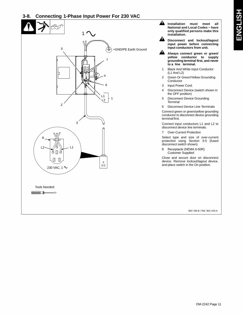
3-8. Connecting 1-Phase Input Power For 230 VAC
803 766-B / Ref. 802 443-A
! Installation must meet allNational and Local Codes − haveonly qualified persons make thisinstallation.
! Disconnect and lockout/tagoutinput power before connectinginput conductors from unit.
! Always connect green or green/yellow conductor to supplygrounding terminal first, and neverto a line terminal.
1 Black And White Input Conductor(L1 And L2)
2 Green Or Green/Yellow GroundingConductor
3 Input Power Cord.
4 Disconnect Device (switch shown inthe OFF position)
5 Disconnect Device GroundingTerminal
6 Disconnect Device Line Terminals
Connect green or green/yellow groundingconductor to disconnect device groundingterminal first.
Connect input conductors L1 and L2 todisconnect device line terminals.
7 Over-Current Protection
Select type and size of over-currentprotection using Section 3-5 (fuseddisconnect switch shown).
8 Receptacle (NEMA 6-50R)Customer Supplied
Close and secure door on disconnectdevice. Remove lockout/tagout device,and place switch in the On position.
4
3
L1L2
1
=GND/PE Earth Ground
2
1
5
6
7
Tools Needed:
L1L2
230 VAC, 1
8
OM-2242 Page 12
SECTION 4 − OPERATION
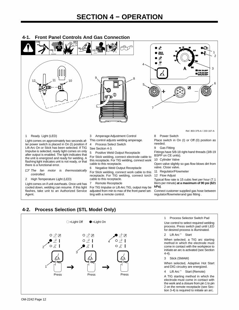
1 Ready Light (LED)
Light comes on approximately two seconds af-ter power switch is placed in On (I) position ifLift-Arc On or Stick has been selected. If TIGImpulse is selected, ready light comes on onlyafter output is enabled. The light indicates thatthe unit is energized and ready for welding. Aflashing light indicates unit is not ready, or thatthere is a functional error.
� The fan motor is thermostaticallycontrolled.
2 High Temperature Light (LED)
Light comes on if unit overheats. Once unit hascooled down, welding can resume. If this lightflashes, take unit to an Authorized ServiceAgent.
3 Amperage Adjustment ControlThis control adjusts welding amperage.4 Process Select SwitchSee Section 4-3.5 Positive Weld Output ReceptacleFor Stick welding, connect electrode cable tothis receptacle. For TIG welding, connect workcable to this receptacle.6 Negative Weld Output ReceptacleFor Stick welding, connect work cable to thisreceptacle. For TIG welding, connect torchcable to this receptacle.7 Remote ReceptacleFor TIG Impulse or Lift-Arc TIG, output may beadjusted from min to max of the front panel set-ting with a remote control.
8 Power SwitchPlace switch in On (I) or Off (0) position asneeded.9 Gas FittingFittings have 5/8-18 right-hand threads (3/8-19BSPP on CE units).10 Cylinder ValveOpen valve slightly so gas flow blows dirt fromvalve. Close valve.11 Regulator/Flowmeter12 Flow AdjustTypical flow rate is 15 cubic feet per hour (7.1liters per minute) at a maximum of 90 psi (621kPa).Connect customer supplied gas hose betweenregulator/flowmeter and gas fitting .
4-1. Front Panel Controls And Gas Connection
Ref. 803 375-A / 233 167-A
7
5 6
4
8
3
21
11 10129
4-2. Process Selection (STL Model Only)
1 Process Selector Switch Pad
Use control to select required weldingprocess. Press switch pad until LEDfor desired process is illuminated.
2 Lift Arc� Start
When selected, a TIG arc startingmethod in which the electrode mustcome in contact with the workpiece toinitiate an arc is activated (see Section4-4).
3 Stick (SMAW)
When selected, Adaptive Hot Startand DIG circuitry are energized.
4 Lift Arc� Start (Remote)
A TIG starting method in which theelectrode must come in contact withthe work and a closure from pin 1 to pin2 on the remote receptacle (see Sec-tion 3-4) is required to initiate an arc.
1
Press Press
2
3
=Light Off =Light On
Press
4
EN
GL
ISH
OM-2242 Page 13
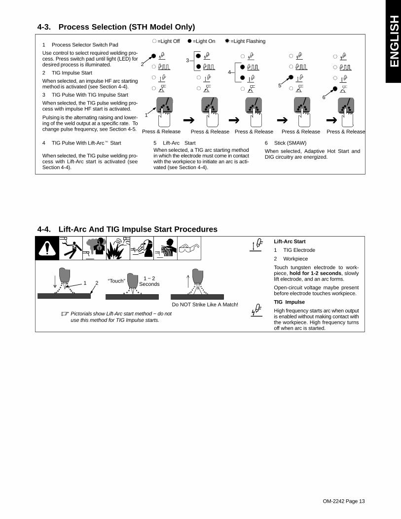
4-3. Process Selection (STH Model Only)
1 Process Selector Switch Pad
Use control to select required welding pro-cess. Press switch pad until light (LED) fordesired process is illuminated.
2 TIG Impulse Start
When selected, an impulse HF arc startingmethod is activated (see Section 4-4).
3 TIG Pulse With TIG Impulse Start
When selected, the TIG pulse welding pro-cess with impulse HF start is activated.
Pulsing is the alternating raising and lower-ing of the weld output at a specific rate. Tochange pulse frequency, see Section 4-5.
4 TIG Pulse With Lift-Arc� Start
When selected, the TIG pulse welding pro-cess with Lift-Arc start is activated (seeSection 4-4).
5 Lift-Arc StartWhen selected, a TIG arc starting methodin which the electrode must come in contactwith the workpiece to initiate an arc is acti-vated (see Section 4-4).
6 Stick (SMAW)
When selected, Adaptive Hot Start andDIG circuitry are energized.
1
Press & Release Press & Release Press & Release Press & Release Press & Release
23
4
5
6
=Light Off =Light On =Light Flashing
4-4. Lift-Arc And TIG Impulse Start ProceduresLift-Arc Start
1 TIG Electrode
2 Workpiece
Touch tungsten electrode to work-piece, hold for 1-2 seconds, slowlylift electrode, and an arc forms.
Open-circuit voltage maybe presentbefore electrode touches workpiece.
TIG Impulse
High frequency starts arc when outputis enabled without making contact withthe workpiece. High frequency turnsoff when arc is started.
11 − 2
Seconds“Touch”
Do NOT Strike Like A Match!
2
� Pictorials show Lift-Arc start method − do notuse this method for TIG Impulse starts.
OM-2242 Page 14
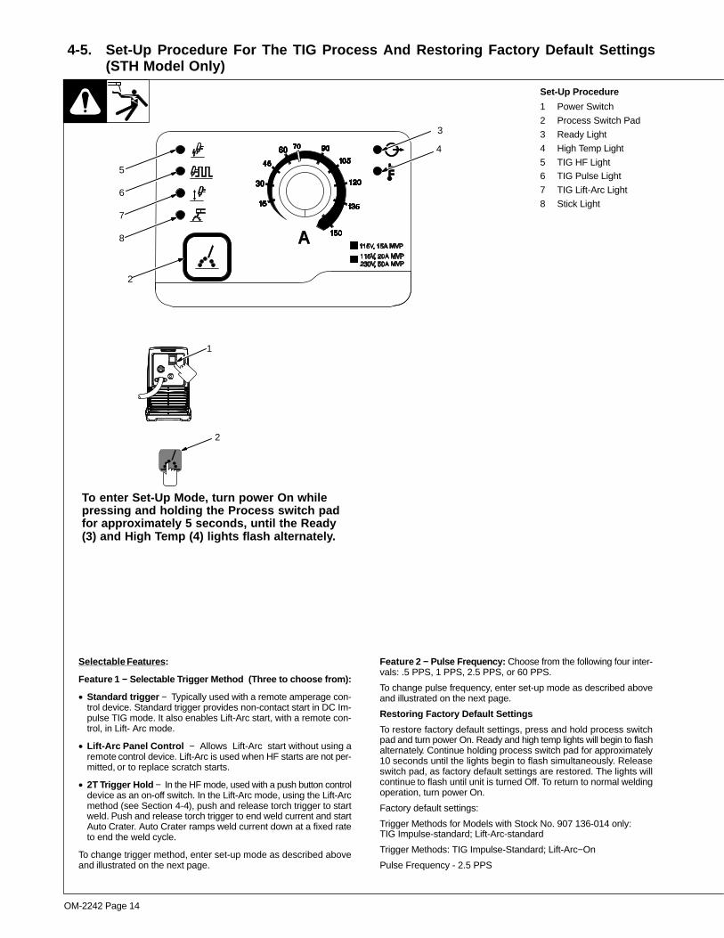
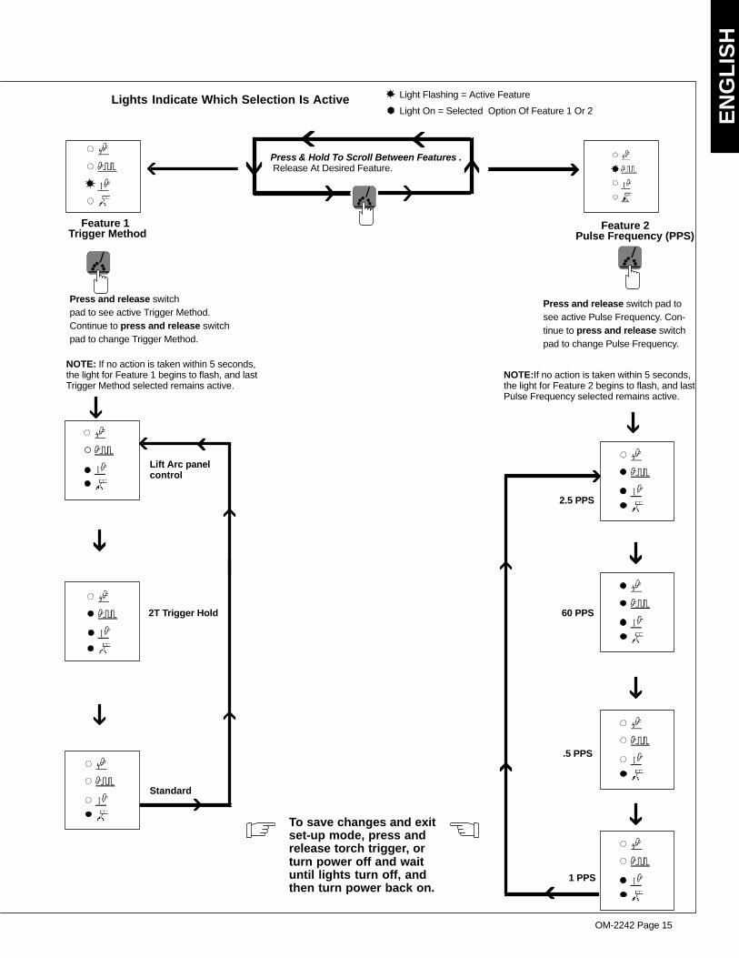
4-5. Set-Up Procedure For The TIG Process And Restoring Factory Default Settings(STH Model Only)
Selectable Features:
Feature 1 − Selectable Trigger Method (Three to choose from):
• Standard trigger − Typically used with a remote amperage con-trol device. Standard trigger provides non-contact start in DC Im-pulse TIG mode. It also enables Lift-Arc start, with a remote con-trol, in Lift- Arc mode.
• Lift-Arc Panel Control − Allows Lift-Arc start without using aremote control device. Lift-Arc is used when HF starts are not per-mitted, or to replace scratch starts.
• 2T Trigger Hold − In the HF mode, used with a push button controldevice as an on-off switch. In the Lift-Arc mode, using the Lift-Arcmethod (see Section 4-4), push and release torch trigger to startweld. Push and release torch trigger to end weld current and startAuto Crater. Auto Crater ramps weld current down at a fixed rateto end the weld cycle.
To change trigger method, enter set-up mode as described aboveand illustrated on the next page.
Feature 2 − Pulse Frequency: Choose from the following four inter-vals: .5 PPS, 1 PPS, 2.5 PPS, or 60 PPS.
To change pulse frequency, enter set-up mode as described aboveand illustrated on the next page.
Restoring Factory Default Settings
To restore factory default settings, press and hold process switchpad and turn power On. Ready and high temp lights will begin to flashalternately. Continue holding process switch pad for approximately10 seconds until the lights begin to flash simultaneously. Releaseswitch pad, as factory default settings are restored. The lights willcontinue to flash until unit is turned Off. To return to normal weldingoperation, turn power On.
Factory default settings:
Trigger Methods for Models with Stock No. 907 136-014 only:TIG Impulse-standard; Lift-Arc-standard
Trigger Methods: TIG Impulse-Standard; Lift-Arc−On
Pulse Frequency - 2.5 PPS
Set-Up Procedure
1 Power Switch
2 Process Switch Pad
3 Ready Light
4 High Temp Light
5 TIG HF Light6 TIG Pulse Light
7 TIG Lift-Arc Light
8 Stick Light
1
To enter Set-Up Mode, turn power On whilepressing and holding the Process switch padfor approximately 5 seconds, until the Ready(3) and High Temp (4) lights flash alternately.
2
3
4
2
5
6
7
8
EN
GL
ISH
OM-2242 Page 15
Standard
Lift Arc panelcontrol
2T Trigger Hold
2.5 PPS
60 PPS
.5 PPS
1 PPS
Lights Indicate Which Selection Is Active Light On = Selected Option Of Feature 1 Or 2
Light Flashing = Active Feature
To save changes and exitset-up mode, press andrelease torch trigger, orturn power off and waituntil lights turn off, andthen turn power back on.
Press & Hold To Scroll Between Features . Release At Desired Feature.
Feature 1 Feature 2Trigger Method Pulse Frequency (PPS)
NOTE: If no action is taken within 5 seconds,the light for Feature 1 begins to flash, and lastTrigger Method selected remains active.
Press and release switchpad to see active Trigger Method.Continue to press and release switchpad to change Trigger Method.
Press and release switch pad tosee active Pulse Frequency. Con-tinue to press and release switchpad to change Pulse Frequency.
NOTE:If no action is taken within 5 seconds,the light for Feature 2 begins to flash, and lastPulse Frequency selected remains active.
OM-2242 Page 16
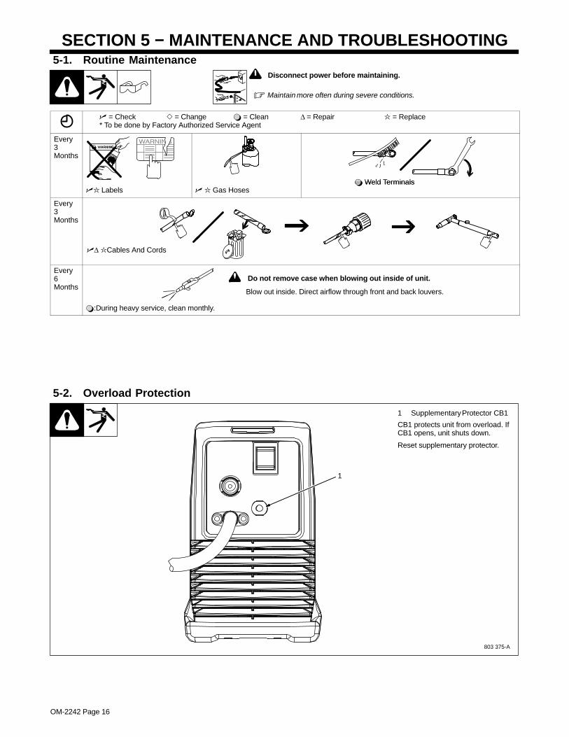
SECTION 5 − MAINTENANCE AND TROUBLESHOOTING5-1. Routine Maintenance
� Maintain more often during severe conditions.
! Disconnect power before maintaining.
� = Check � = Change � = Clean Δ = Repair = Replace* To be done by Factory Authorized Service Agent
Every3Months
� Weld Terminals� Labels � Gas Hoses
� Weld Terminals
Every3Months
�Δ Cables And Cords
Every6Months
Blow out inside. Direct airflow through front and back louvers.
! Do not remove case when blowing out inside of unit.
�:During heavy service, clean monthly.
Blow out inside. Direct airflow through front and back louvers.
5-2. Overload Protection
803 375-A
1 Supplementary Protector CB1
CB1 protects unit from overload. IfCB1 opens, unit shuts down.
Reset supplementary protector.
1

EN
GL
ISH
OM-2242 Page 17
5-3. Troubleshooting
Trouble Remedy
No weld output; unit completely inop-erative; ready light (LED) Off.
Place line disconnect switch in On position.No weld output; unit completely inop-erative; ready light (LED) Off. Check and replace line fuse(s), if necessary, or reset circuit breaker.
Be sure power cord is plugged in and that receptacle is receiving input power.
No weld output; ready light (LED) On. Check and secure loose weld cable(s) into receptacle(s).
Check and correct poor connection of work clamp to workpiece.
No weld output; high temperature light(LED) On.
Unit overheated causing thermal shutdown. Allow unit to cool with fan On (see Section 3-2).No weld output; high temperature light(LED) On. Reduce duty cycle or amperage.
Check and correct blocked/poor airflow to unit (see Section 3-7).
No weld output; high temperature light(LED) Flashing.
Turn Power Off and back On again. If light continues to flash, check with Factory Authorized ServiceAgent.
No weld output. Blue light (LED) flashescontinuously, yellow light (LED) off.
Line voltage too high or too low. Line voltage must be within ±10%.continuously, yellow light (LED) off.
Unit needs to reset. Cycle power off and back on. If problem is not corrected, contact Factory AuthorizedService Agent.
No weld output. Blue light (LED) flashes3 times repeatedly, yellow light (LED) off.
Remote trigger left on. Turn off remote trigger, wait five seconds, and restart operation.
No weld output. Blue light (LED) flashes4 times repeatedly, yellow light (LED) off.
Unit needs to reset. Cycle power off and back on. If problem is not corrected, contact Factory AuthorizedService Agent.
Erratic or improper welding arc or out-put.
Use proper size and type of weld cable (see your Distributor).Erratic or improper welding arc or out-put. Clean and tighten weld connections.
Check and reverse polarity; check and correct poor connections to workpiece.
Fan not operating. Unit not warmed up enough to require fan cooling.
Check for and remove anything blocking fan movement.
Have Factory Authorized Service Agent check fan motor and control circuitry.
Stick welding problems: Hard starts;poor welding characteristics; unusual
Use proper type and size of electrode.poor welding characteristics; unusualspattering. Check and reverse electrode polarity; check and correct poor connections.
Make sure a remote control is not connected.
TIG welding problems: Wandering arc;hard starts; poor welding characteris-
Use proper type and size of tungsten.hard starts; poor welding characteris-tics; spattering problems. Use properly prepared tungsten.
Check and reverse electrode polarity.
TIG welding problems: Tungsten elec-trode oxidizing and not remaining bright
Shield weld zone from drafts.TIG welding problems: Tungsten elec-trode oxidizing and not remaining brightafter welding.
Check for correct type shielding gas.after welding.
Check and tighten gas fittings.
Check and change electrode polarity.
OM-2242 Page 18
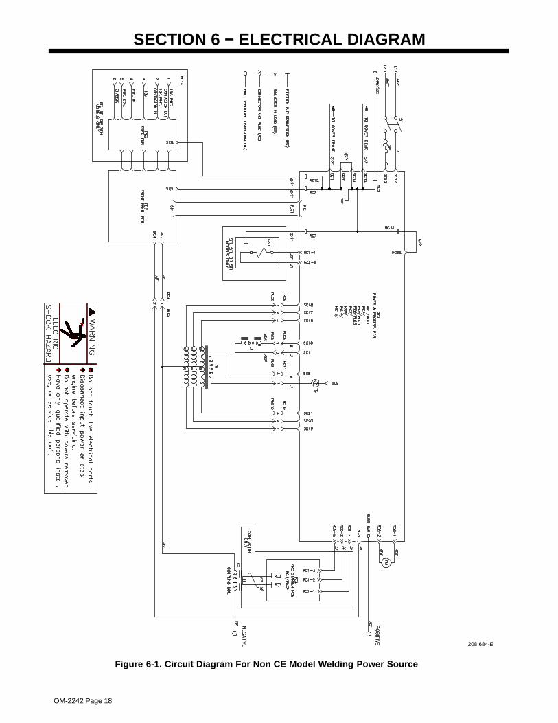
SECTION 6 − ELECTRICAL DIAGRAM
208 684-E
Figure 6-1. Circuit Diagram For Non CE Model Welding Power Source
EN
GL
ISH
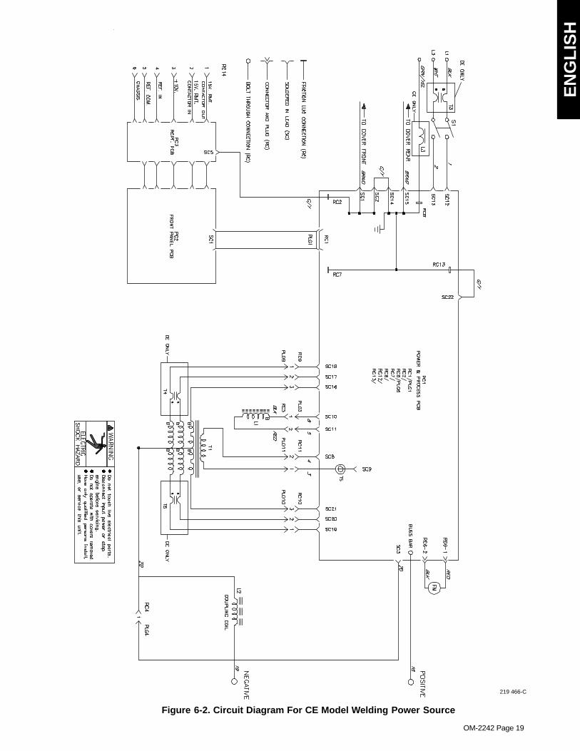
OM-2242 Page 19
219 466-C
Figure 6-2. Circuit Diagram For CE Model Welding Power Source
OM-2242 Page 20
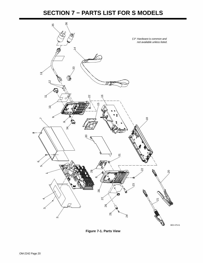
SECTION 7 − PARTS LIST FOR S MODELS
� Hardware is common andnot available unless listed.
803 475-G
20
21
18
22
24
25
2627
28
23
2
34
1
56
7
8
910
11
12
13
14
1516
30
8
29
31
22
33
34
35 36
Figure 7-1. Parts View
EN
GL
ISH
OM-2242 Page 21
DescriptionPartNo.
Dia.Mkgs.
ItemNo. Quantity
1 PC1 222 765 Kit, pcb assy (windtunnel w/cmpnts) 1. . . . . . . . . . . . . . . . . . . . . . . . . . . . . . . . . . . . . . . . . . . . . 1 PC1 230 210 Kit, pcb assy (windtunnel w/cmpnts) (CE ROHS models) 1. . . . . . . . . . . . . . . . . . . . . . . . . . . 2 208 701 Insulator w/label 1. . . . . . . . . . . . . . . . . . . . . . . . . . . . . . . . . . . . . . . . . . . . . . . . . . . . . . . . . . . . . . . . . . . 3 146 549 Fastener, push-in 1. . . . . . . . . . . . . . . . . . . . . . . . . . . . . . . . . . . . . . . . . . . . . . . . . . . . . . . . . . . . . . . . . . 4 208 622 Label, warning 1. . . . . . . . . . . . . . . . . . . . . . . . . . . . . . . . . . . . . . . . . . . . . . . . . . . . . . . . . . . . . . . . . . . . . 5 208 627 Label, warning 1. . . . . . . . . . . . . . . . . . . . . . . . . . . . . . . . . . . . . . . . . . . . . . . . . . . . . . . . . . . . . . . . . . . . . 5 219 674 Label, warning (CE modles) 1. . . . . . . . . . . . . . . . . . . . . . . . . . . . . . . . . . . . . . . . . . . . . . . . . . . . . . . . . 6 195 666 Screw, 010-32x .50 torx 2. . . . . . . . . . . . . . . . . . . . . . . . . . . . . . . . . . . . . . . . . . . . . . . . . . . . . . . . . . . . . 7 208 700 Wrapper w/label 1. . . . . . . . . . . . . . . . . . . . . . . . . . . . . . . . . . . . . . . . . . . . . . . . . . . . . . . . . . . . . . . . . . . 8 208 558 Term, friction .250 x .032 2. . . . . . . . . . . . . . . . . . . . . . . . . . . . . . . . . . . . . . . . . . . . . . . . . . . . . . . . . . . . 9 233 178 Panel, rear w/label 1. . . . . . . . . . . . . . . . . . . . . . . . . . . . . . . . . . . . . . . . . . . . . . . . . . . . . . . . . . . . . . . . . 9 219 983 Panel, rear w/label (CE models) 1. . . . . . . . . . . . . . . . . . . . . . . . . . . . . . . . . . . . . . . . . . . . . . . . . . . . . .
10 233 171 Nameplate, rear 1. . . . . . . . . . . . . . . . . . . . . . . . . . . . . . . . . . . . . . . . . . . . . . . . . . . . . . . . . . . . . . . . . . . 10 219 881 Nameplate, rear (CE models) 1. . . . . . . . . . . . . . . . . . . . . . . . . . . . . . . . . . . . . . . . . . . . . . . . . . . . . . . . 11 208 550 Switch, rocker dpst 16A 250 VAC 1. . . . . . . . . . . . . . . . . . . . . . . . . . . . . . . . . . . . . . . . . . . . . . . . . . . . 12 208 536 Screw, K50 x 25 rnd washer, hd-trx 2. . . . . . . . . . . . . . . . . . . . . . . . . . . . . . . . . . . . . . . . . . . . . . . . . . . 13 225 180 Cable, power 1. . . . . . . . . . . . . . . . . . . . . . . . . . . . . . . . . . . . . . . . . . . . . . . . . . . . . . . . . . . . . . . . . . . . . . 14 208 548 Strap, shoulder 1. . . . . . . . . . . . . . . . . . . . . . . . . . . . . . . . . . . . . . . . . . . . . . . . . . . . . . . . . . . . . . . . . . . . 15 FM 208 496 Fan w/leads and plug 1. . . . . . . . . . . . . . . . . . . . . . . . . . . . . . . . . . . . . . . . . . . . . . . . . . . . . . . . . . 16 L1, L2, T1 208 538 Windtunnel, magnetics w/cmpnt 1. . . . . . . . . . . . . . . . . . . . . . . . . . . . . . . . . . . . . . . . . . . 16 L1, L2, T1 219 168 Windtunnel, magnetics w/cmpnt (CE models) 1. . . . . . . . . . . . . . . . . . . . . . . . . . . . . . . . 18 Base w/label, order by serial number 1. . . . . . . . . . . . . . . . . . . . . . . . . . . . . . . . . . . . . . . . . . . . . . . . . . . . . . . . . . 20 208 561 Work Cable 1. . . . . . . . . . . . . . . . . . . . . . . . . . . . . . . . . . . . . . . . . . . . . . . . . . . . . . . . . . . . . . . . . . . . . . . 21 208 596 Holder, electrode 1. . . . . . . . . . . . . . . . . . . . . . . . . . . . . . . . . . . . . . . . . . . . . . . . . . . . . . . . . . . . . . . . . . . 22 208 535 Screw, k50 x 12 rnd washer hd-trx 4. . . . . . . . . . . . . . . . . . . . . . . . . . . . . . . . . . . . . . . . . . . . . . . . . . . 23 208 612 Receptacle, twist lock power/gas 1. . . . . . . . . . . . . . . . . . . . . . . . . . . . . . . . . . . . . . . . . . . . . . . . . . . . . 24 229 337 Screw, m5-.8 x 12 soc hd -torx 1. . . . . . . . . . . . . . . . . . . . . . . . . . . . . . . . . . . . . . . . . . . . . . . . . . . . . . . 25 208 498 Receptacle, twist lock power 1. . . . . . . . . . . . . . . . . . . . . . . . . . . . . . . . . . . . . . . . . . . . . . . . . . . . . . . . 26 174 992 Knob, pointer 1. . . . . . . . . . . . . . . . . . . . . . . . . . . . . . . . . . . . . . . . . . . . . . . . . . . . . . . . . . . . . . . . . . . . . . 27 Nameplate, front (order by model and serial number) 1. . . . . . . . . . . . . . . . . . . . . . . . . . . . . . . . . . . . . . . . . . . . 27 Nameplate, front (CE models) (order by model and serial number) 1. . . . . . . . . . . . . . . . . . . . . . . . . . . . . . . . . 28 233 179 Panel, front w/nameplate 1. . . . . . . . . . . . . . . . . . . . . . . . . . . . . . . . . . . . . . . . . . . . . . . . . . . . . . . . . . . . 28 219 170 Panel, front w/nameplate (CE models) 1. . . . . . . . . . . . . . . . . . . . . . . . . . . . . . . . . . . . . . . . . . . . . . . . 29 PC2 212 905 Circuit board, operator interface 1. . . . . . . . . . . . . . . . . . . . . . . . . . . . . . . . . . . . . . . . . . . . . . . . . 29 PC2 226 864 Circuit board, operator interface (CE ROHS models) 1. . . . . . . . . . . . . . . . . . . . . . . . . . . . . . . 30 208 556 Insulator, heat sink 1. . . . . . . . . . . . . . . . . . . . . . . . . . . . . . . . . . . . . . . . . . . . . . . . . . . . . . . . . . . . . . . . . 31 208 497 Nut, m08-1.2 13 mm hex 8.3 mm t semi cone washer 1. . . . . . . . . . . . . . . . . . . . . . . . . . . . . . . . . . . 33 T3 219 076 Core ferrite (CE models) 1. . . . . . . . . . . . . . . . . . . . . . . . . . . . . . . . . . . . . . . . . . . . . . . . . . . . . . . . 34 CB1 225 844 Supplementary Protector 1. . . . . . . . . . . . . . . . . . . . . . . . . . . . . . . . . . . . . . . . . . . . . . . . . . . . . . . 35 219 258 Adapter, power cable 6−50P (230V/50A) 1. . . . . . . . . . . . . . . . . . . . . . . . . . . . . . . . . . . . . . . . . . . . . . 36 219 261 Adapter, power cable 5−15P (115V/15A) 1. . . . . . . . . . . . . . . . . . . . . . . . . . . . . . . . . . . . . . . . . . . . . .
To maintain the factory original performance of your equipment, use only Manufacturer’s SuggestedReplacement Parts. Model and serial number required when ordering parts from your local distributor.
OM-2242 Page 22
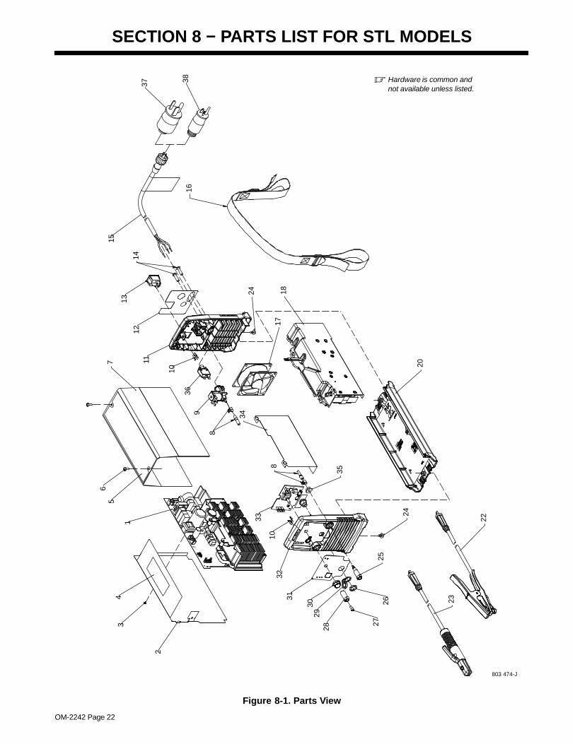
SECTION 8 − PARTS LIST FOR STL MODELS
� Hardware is common andnot available unless listed.
803 474-J
22
23
20
24
27
2829
30
3132
2526
2
34
1
67
8
9
10
1112
13
14
15
16
1718
34
10
33
35
8
24
36
5
37 38
Figure 8-1. Parts View
EN
GL
ISH
OM-2242 Page 23
DescriptionPartNo.
Dia.Mkgs.
ItemNo. Quantity
1 PC1 222 765 Kit, pcb assy (windtunnel w/cmpnts) 1. . . . . . . . . . . . . . . . . . . . . . . . . . . . . . . . . . . . . . . . . . . . . 2 208 701 Insulator w/label 1. . . . . . . . . . . . . . . . . . . . . . . . . . . . . . . . . . . . . . . . . . . . . . . . . . . . . . . . . . . . . . . . . . . 3 146 549 Fastener, push-in 1. . . . . . . . . . . . . . . . . . . . . . . . . . . . . . . . . . . . . . . . . . . . . . . . . . . . . . . . . . . . . . . . . . 4 208 622 Label, warning 1. . . . . . . . . . . . . . . . . . . . . . . . . . . . . . . . . . . . . . . . . . . . . . . . . . . . . . . . . . . . . . . . . . . . . 5 208 627 Label, warning 1. . . . . . . . . . . . . . . . . . . . . . . . . . . . . . . . . . . . . . . . . . . . . . . . . . . . . . . . . . . . . . . . . . . . . 5 219 674 Label, warning (CE modles) 1. . . . . . . . . . . . . . . . . . . . . . . . . . . . . . . . . . . . . . . . . . . . . . . . . . . . . . . . . 6 195 666 Screw, 010-32x .50 torx 2. . . . . . . . . . . . . . . . . . . . . . . . . . . . . . . . . . . . . . . . . . . . . . . . . . . . . . . . . . . . . 7 208 700 Wrapper w/label 1. . . . . . . . . . . . . . . . . . . . . . . . . . . . . . . . . . . . . . . . . . . . . . . . . . . . . . . . . . . . . . . . . . . 8 208 569 Hose and clamps (2) 1. . . . . . . . . . . . . . . . . . . . . . . . . . . . . . . . . . . . . . . . . . . . . . . . . . . . . . . . . . . . . . . 9 GS1 219 967 Valve, gas w/fittings 1. . . . . . . . . . . . . . . . . . . . . . . . . . . . . . . . . . . . . . . . . . . . . . . . . . . . . . . . . . .
10 208 558 Term, friction .250 x .032 2. . . . . . . . . . . . . . . . . . . . . . . . . . . . . . . . . . . . . . . . . . . . . . . . . . . . . . . . . . . . 11 233 175 Panel, rear w/label 1. . . . . . . . . . . . . . . . . . . . . . . . . . . . . . . . . . . . . . . . . . . . . . . . . . . . . . . . . . . . . . . . . 12 233 170 Nameplate, rear 1. . . . . . . . . . . . . . . . . . . . . . . . . . . . . . . . . . . . . . . . . . . . . . . . . . . . . . . . . . . . . . . . . . . 13 208 550 Switch, rocker dpst 16A 250 VAC 1. . . . . . . . . . . . . . . . . . . . . . . . . . . . . . . . . . . . . . . . . . . . . . . . . . . . 14 208 536 Screw, K50 x 25 rnd washer, hd-trx 2. . . . . . . . . . . . . . . . . . . . . . . . . . . . . . . . . . . . . . . . . . . . . . . . . . . 15 225 180 Cable, power 1. . . . . . . . . . . . . . . . . . . . . . . . . . . . . . . . . . . . . . . . . . . . . . . . . . . . . . . . . . . . . . . . . . . . . . 16 208 548 Strap, shoulder 1. . . . . . . . . . . . . . . . . . . . . . . . . . . . . . . . . . . . . . . . . . . . . . . . . . . . . . . . . . . . . . . . . . . . 17 FM 208 496 Fan w/leads and plug 1. . . . . . . . . . . . . . . . . . . . . . . . . . . . . . . . . . . . . . . . . . . . . . . . . . . . . . . . . . 18 L1, L2, T1 208 538 Windtunnel, magnetics w/cmpnt 1. . . . . . . . . . . . . . . . . . . . . . . . . . . . . . . . . . . . . . . . . . . 20 Base w/label, order by serial number 1. . . . . . . . . . . . . . . . . . . . . . . . . . . . . . . . . . . . . . . . . . . . . . . . . . . . . . . . . . 22 208 561 Work Cable 1. . . . . . . . . . . . . . . . . . . . . . . . . . . . . . . . . . . . . . . . . . . . . . . . . . . . . . . . . . . . . . . . . . . . . . . 23 208 596 Holder, electrode 1. . . . . . . . . . . . . . . . . . . . . . . . . . . . . . . . . . . . . . . . . . . . . . . . . . . . . . . . . . . . . . . . . . . 24 208 535 Screw, k50 x 12 rnd washer hd-trx 4. . . . . . . . . . . . . . . . . . . . . . . . . . . . . . . . . . . . . . . . . . . . . . . . . . . 25 208 612 Receptacle, twist lock power/gas 1. . . . . . . . . . . . . . . . . . . . . . . . . . . . . . . . . . . . . . . . . . . . . . . . . . . . . 26 208 588 Nut, plastic 625-27.81 hex x .14 1. . . . . . . . . . . . . . . . . . . . . . . . . . . . . . . . . . . . . . . . . . . . . . . . . . . . . . 27 229 337 Screw, m5-.8 x 12 soc hd -torx 1. . . . . . . . . . . . . . . . . . . . . . . . . . . . . . . . . . . . . . . . . . . . . . . . . . . . . . . 28 208 498 Receptacle, twist lock power 1. . . . . . . . . . . . . . . . . . . . . . . . . . . . . . . . . . . . . . . . . . . . . . . . . . . . . . . . 29 208 589 Cover, dust 1. . . . . . . . . . . . . . . . . . . . . . . . . . . . . . . . . . . . . . . . . . . . . . . . . . . . . . . . . . . . . . . . . . . . . . . 30 174 992 Knob, pointer 1. . . . . . . . . . . . . . . . . . . . . . . . . . . . . . . . . . . . . . . . . . . . . . . . . . . . . . . . . . . . . . . . . . . . . . 31 Nameplate, front (order by model and serial number) 1. . . . . . . . . . . . . . . . . . . . . . . . . . . . . . . . . . . . . . . . . . . . 32 233 177 Panel, front w/nameplate 1. . . . . . . . . . . . . . . . . . . . . . . . . . . . . . . . . . . . . . . . . . . . . . . . . . . . . . . . . . . . 33 PC2, PC3 217 787 Circuit board, operator interface 1. . . . . . . . . . . . . . . . . . . . . . . . . . . . . . . . . . . . . . . . . . . . 34 208 556 Insualtor, heat sink 1. . . . . . . . . . . . . . . . . . . . . . . . . . . . . . . . . . . . . . . . . . . . . . . . . . . . . . . . . . . . . . . . . 35 208 497 Nut, m08-1.2 13 mm hex 8.3 mm t semi cone washer 1. . . . . . . . . . . . . . . . . . . . . . . . . . . . . . . . . . . 36 CB1 225 844 Supplementary Protector 1. . . . . . . . . . . . . . . . . . . . . . . . . . . . . . . . . . . . . . . . . . . . . . . . . . . . . . . 37 219 258 Adapter, power cable 6−50P (230V/50A) 1. . . . . . . . . . . . . . . . . . . . . . . . . . . . . . . . . . . . . . . . . . . . . . 38 219 261 Adapter, power cable 5−15P (115V/15A) 1. . . . . . . . . . . . . . . . . . . . . . . . . . . . . . . . . . . . . . . . . . . . . .
To maintain the factory original performance of your equipment, use only Manufacturer’s SuggestedReplacement Parts. Model and serial number required when ordering parts from your local distributor.
OM-2242 Page 24
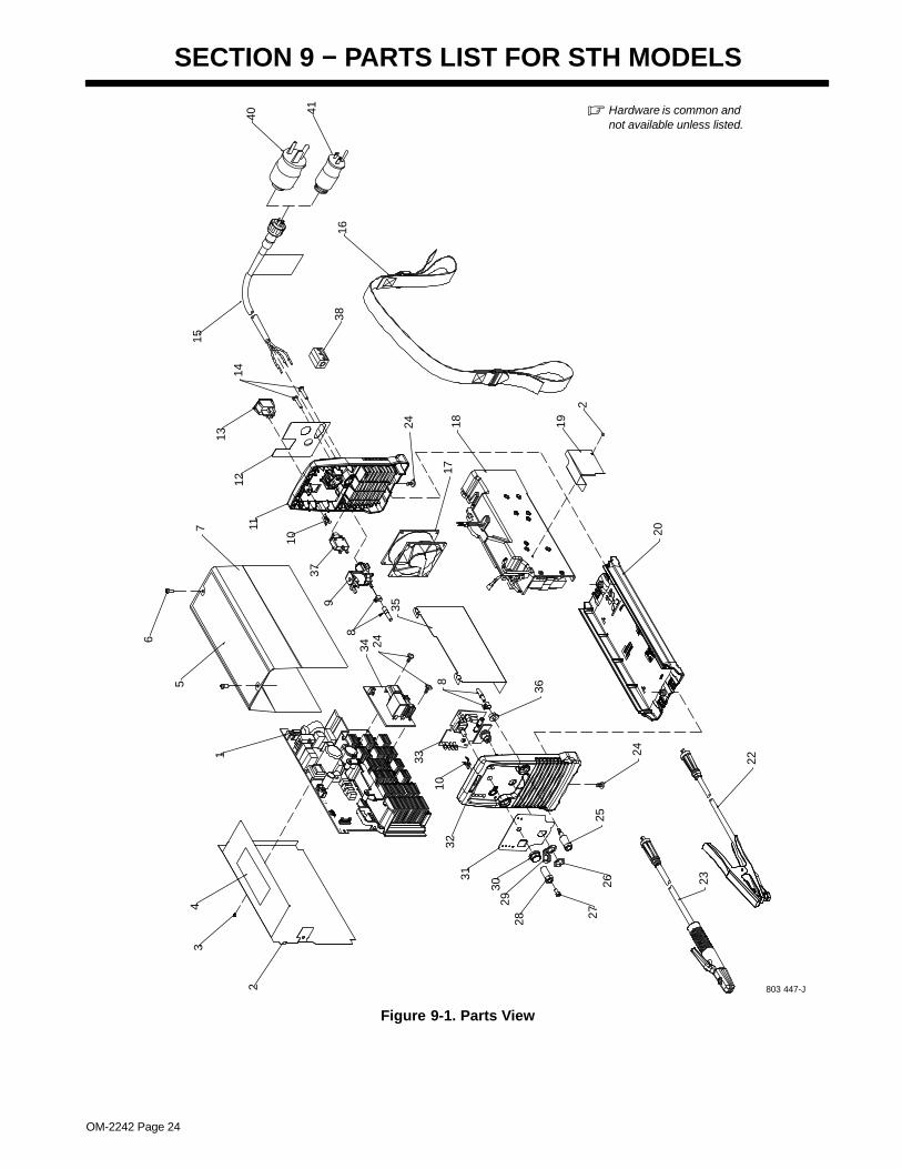
SECTION 9 − PARTS LIST FOR STH MODELS
� Hardware is common andnot available unless listed.
803 447-J
22
23
20
24
272829
30
3132
2526
2
34
1
5
6
7 1112
13
14
15
16
1718 19
34 24
35
10
33
36
8
24
2
388
9
10
37
40 41
Figure 9-1. Parts View
OM-2242 Page 25
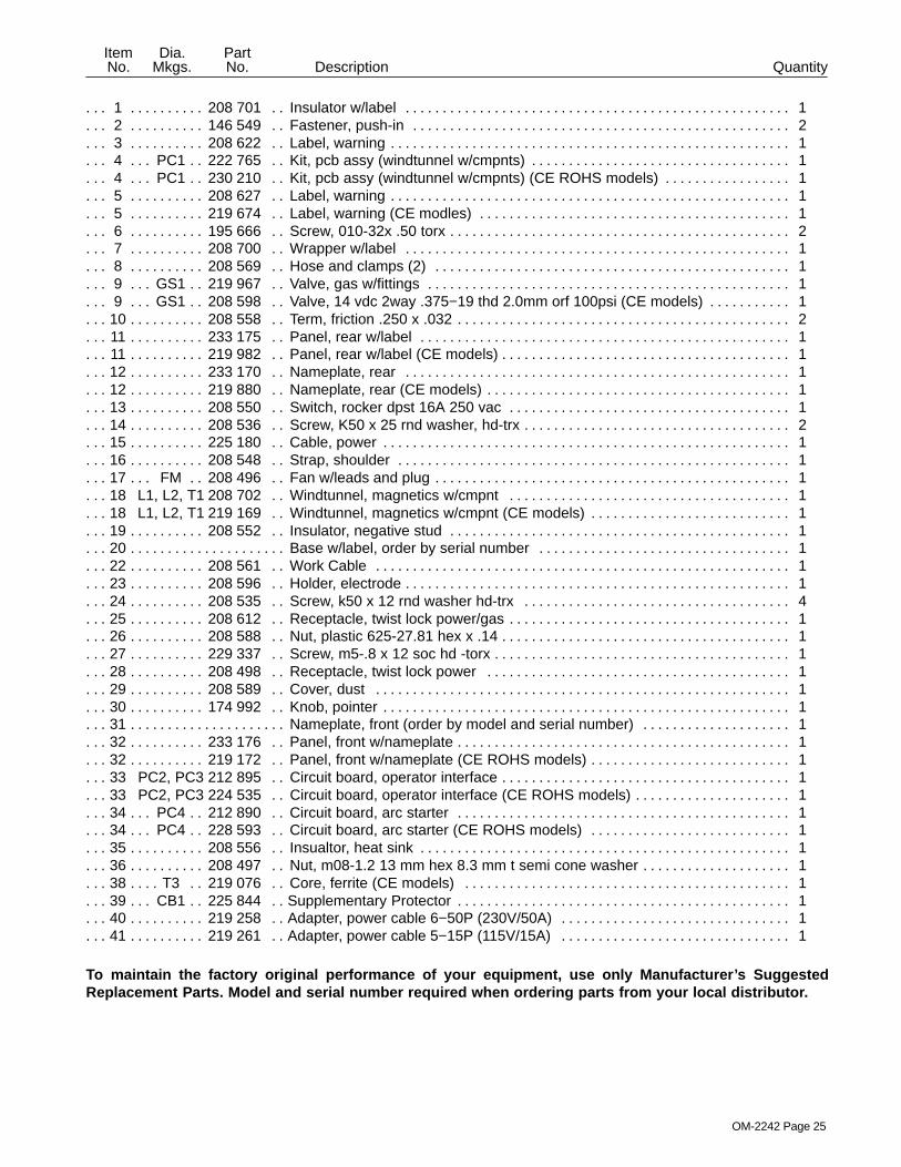
DescriptionPartNo.
Dia.Mkgs.
ItemNo. Quantity
1 208 701 Insulator w/label 1. . . . . . . . . . . . . . . . . . . . . . . . . . . . . . . . . . . . . . . . . . . . . . . . . . . . . . . . . . . . . . . . . . . 2 146 549 Fastener, push-in 2. . . . . . . . . . . . . . . . . . . . . . . . . . . . . . . . . . . . . . . . . . . . . . . . . . . . . . . . . . . . . . . . . . 3 208 622 Label, warning 1. . . . . . . . . . . . . . . . . . . . . . . . . . . . . . . . . . . . . . . . . . . . . . . . . . . . . . . . . . . . . . . . . . . . . 4 PC1 222 765 Kit, pcb assy (windtunnel w/cmpnts) 1. . . . . . . . . . . . . . . . . . . . . . . . . . . . . . . . . . . . . . . . . . . . . 4 PC1 230 210 Kit, pcb assy (windtunnel w/cmpnts) (CE ROHS models) 1. . . . . . . . . . . . . . . . . . . . . . . . . . . 5 208 627 Label, warning 1. . . . . . . . . . . . . . . . . . . . . . . . . . . . . . . . . . . . . . . . . . . . . . . . . . . . . . . . . . . . . . . . . . . . . 5 219 674 Label, warning (CE modles) 1. . . . . . . . . . . . . . . . . . . . . . . . . . . . . . . . . . . . . . . . . . . . . . . . . . . . . . . . . 6 195 666 Screw, 010-32x .50 torx 2. . . . . . . . . . . . . . . . . . . . . . . . . . . . . . . . . . . . . . . . . . . . . . . . . . . . . . . . . . . . . 7 208 700 Wrapper w/label 1. . . . . . . . . . . . . . . . . . . . . . . . . . . . . . . . . . . . . . . . . . . . . . . . . . . . . . . . . . . . . . . . . . . 8 208 569 Hose and clamps (2) 1. . . . . . . . . . . . . . . . . . . . . . . . . . . . . . . . . . . . . . . . . . . . . . . . . . . . . . . . . . . . . . . 9 GS1 219 967 Valve, gas w/fittings 1. . . . . . . . . . . . . . . . . . . . . . . . . . . . . . . . . . . . . . . . . . . . . . . . . . . . . . . . . . . 9 GS1 208 598 Valve, 14 vdc 2way .375−19 thd 2.0mm orf 100psi (CE models) 1. . . . . . . . . . . . . . . . . . . . .
10 208 558 Term, friction .250 x .032 2. . . . . . . . . . . . . . . . . . . . . . . . . . . . . . . . . . . . . . . . . . . . . . . . . . . . . . . . . . . . 11 233 175 Panel, rear w/label 1. . . . . . . . . . . . . . . . . . . . . . . . . . . . . . . . . . . . . . . . . . . . . . . . . . . . . . . . . . . . . . . . . 11 219 982 Panel, rear w/label (CE models) 1. . . . . . . . . . . . . . . . . . . . . . . . . . . . . . . . . . . . . . . . . . . . . . . . . . . . . . 12 233 170 Nameplate, rear 1. . . . . . . . . . . . . . . . . . . . . . . . . . . . . . . . . . . . . . . . . . . . . . . . . . . . . . . . . . . . . . . . . . . 12 219 880 Nameplate, rear (CE models) 1. . . . . . . . . . . . . . . . . . . . . . . . . . . . . . . . . . . . . . . . . . . . . . . . . . . . . . . . 13 208 550 Switch, rocker dpst 16A 250 vac 1. . . . . . . . . . . . . . . . . . . . . . . . . . . . . . . . . . . . . . . . . . . . . . . . . . . . . 14 208 536 Screw, K50 x 25 rnd washer, hd-trx 2. . . . . . . . . . . . . . . . . . . . . . . . . . . . . . . . . . . . . . . . . . . . . . . . . . . 15 225 180 Cable, power 1. . . . . . . . . . . . . . . . . . . . . . . . . . . . . . . . . . . . . . . . . . . . . . . . . . . . . . . . . . . . . . . . . . . . . . 16 208 548 Strap, shoulder 1. . . . . . . . . . . . . . . . . . . . . . . . . . . . . . . . . . . . . . . . . . . . . . . . . . . . . . . . . . . . . . . . . . . . 17 FM 208 496 Fan w/leads and plug 1. . . . . . . . . . . . . . . . . . . . . . . . . . . . . . . . . . . . . . . . . . . . . . . . . . . . . . . . . . 18 L1, L2, T1 208 702 Windtunnel, magnetics w/cmpnt 1. . . . . . . . . . . . . . . . . . . . . . . . . . . . . . . . . . . . . . . . . . . 18 L1, L2, T1 219 169 Windtunnel, magnetics w/cmpnt (CE models) 1. . . . . . . . . . . . . . . . . . . . . . . . . . . . . . . . 19 208 552 Insulator, negative stud 1. . . . . . . . . . . . . . . . . . . . . . . . . . . . . . . . . . . . . . . . . . . . . . . . . . . . . . . . . . . . . 20 Base w/label, order by serial number 1. . . . . . . . . . . . . . . . . . . . . . . . . . . . . . . . . . . . . . . . . . . . . . . . . . . . . . . . . . 22 208 561 Work Cable 1. . . . . . . . . . . . . . . . . . . . . . . . . . . . . . . . . . . . . . . . . . . . . . . . . . . . . . . . . . . . . . . . . . . . . . . 23 208 596 Holder, electrode 1. . . . . . . . . . . . . . . . . . . . . . . . . . . . . . . . . . . . . . . . . . . . . . . . . . . . . . . . . . . . . . . . . . . 24 208 535 Screw, k50 x 12 rnd washer hd-trx 4. . . . . . . . . . . . . . . . . . . . . . . . . . . . . . . . . . . . . . . . . . . . . . . . . . . 25 208 612 Receptacle, twist lock power/gas 1. . . . . . . . . . . . . . . . . . . . . . . . . . . . . . . . . . . . . . . . . . . . . . . . . . . . . 26 208 588 Nut, plastic 625-27.81 hex x .14 1. . . . . . . . . . . . . . . . . . . . . . . . . . . . . . . . . . . . . . . . . . . . . . . . . . . . . . 27 229 337 Screw, m5-.8 x 12 soc hd -torx 1. . . . . . . . . . . . . . . . . . . . . . . . . . . . . . . . . . . . . . . . . . . . . . . . . . . . . . . 28 208 498 Receptacle, twist lock power 1. . . . . . . . . . . . . . . . . . . . . . . . . . . . . . . . . . . . . . . . . . . . . . . . . . . . . . . . 29 208 589 Cover, dust 1. . . . . . . . . . . . . . . . . . . . . . . . . . . . . . . . . . . . . . . . . . . . . . . . . . . . . . . . . . . . . . . . . . . . . . . 30 174 992 Knob, pointer 1. . . . . . . . . . . . . . . . . . . . . . . . . . . . . . . . . . . . . . . . . . . . . . . . . . . . . . . . . . . . . . . . . . . . . . 31 Nameplate, front (order by model and serial number) 1. . . . . . . . . . . . . . . . . . . . . . . . . . . . . . . . . . . . . . . . . . . . 32 233 176 Panel, front w/nameplate 1. . . . . . . . . . . . . . . . . . . . . . . . . . . . . . . . . . . . . . . . . . . . . . . . . . . . . . . . . . . . 32 219 172 Panel, front w/nameplate (CE ROHS models) 1. . . . . . . . . . . . . . . . . . . . . . . . . . . . . . . . . . . . . . . . . . 33 PC2, PC3 212 895 Circuit board, operator interface 1. . . . . . . . . . . . . . . . . . . . . . . . . . . . . . . . . . . . . . . . . . . . 33 PC2, PC3 224 535 Circuit board, operator interface (CE ROHS models) 1. . . . . . . . . . . . . . . . . . . . . . . . . . 34 PC4 212 890 Circuit board, arc starter 1. . . . . . . . . . . . . . . . . . . . . . . . . . . . . . . . . . . . . . . . . . . . . . . . . . . . . . . 34 PC4 228 593 Circuit board, arc starter (CE ROHS models) 1. . . . . . . . . . . . . . . . . . . . . . . . . . . . . . . . . . . . . 35 208 556 Insualtor, heat sink 1. . . . . . . . . . . . . . . . . . . . . . . . . . . . . . . . . . . . . . . . . . . . . . . . . . . . . . . . . . . . . . . . . 36 208 497 Nut, m08-1.2 13 mm hex 8.3 mm t semi cone washer 1. . . . . . . . . . . . . . . . . . . . . . . . . . . . . . . . . . . 38 T3 219 076 Core, ferrite (CE models) 1. . . . . . . . . . . . . . . . . . . . . . . . . . . . . . . . . . . . . . . . . . . . . . . . . . . . . . . 39 CB1 225 844 Supplementary Protector 1. . . . . . . . . . . . . . . . . . . . . . . . . . . . . . . . . . . . . . . . . . . . . . . . . . . . . . . 40 219 258 Adapter, power cable 6−50P (230V/50A) 1. . . . . . . . . . . . . . . . . . . . . . . . . . . . . . . . . . . . . . . . . . . . . . 41 219 261 Adapter, power cable 5−15P (115V/15A) 1. . . . . . . . . . . . . . . . . . . . . . . . . . . . . . . . . . . . . . . . . . . . . .
To maintain the factory original performance of your equipment, use only Manufacturer’s SuggestedReplacement Parts. Model and serial number required when ordering parts from your local distributor.

Notes
Warranty Questions?
Call1-800-4-A-MILLERfor your localMiller distributor.
miller_warr 2007−01
Your distributor also givesyou ...
ServiceYou always get the fast,reliable response youneed. Most replacementparts can be in yourhands in 24 hours.
SupportNeed fast answers to thetough welding questions?Contact your distributor.The expertise of thedistributor and Miller isthere to help you, everystep of the way.
Effective January 1, 2007(Equipment with a serial number preface of “LH” or newer)This limited warranty supersedes all previous Miller warranties and is exclusive with no other
guarantees or warranties expressed or implied.LIMITED WARRANTY − Subject to the terms and conditionsbelow, Miller Electric Mfg. Co., Appleton, Wisconsin, warrants toits original retail purchaser that new Miller equipment sold afterthe effective date of this limited warranty is free of defects inmaterial and workmanship at the time it is shipped by Miller. THISWARRANTY IS EXPRESSLY IN LIEU OF ALL OTHERWARRANTIES, EXPRESS OR IMPLIED, INCLUDING THEWARRANTIES OF MERCHANTABILITY AND FITNESS.
Within the warranty periods listed below, Miller will repair orreplace any warranted parts or components that fail due to suchdefects in material or workmanship. Miller must be notified inwriting within thirty (30) days of such defect or failure, at whichtime Miller will provide instructions on the warranty claimprocedures to be followed.
Miller shall honor warranty claims on warranted equipment listedbelow in the event of such a failure within the warranty timeperiods. All warranty time periods start on the delivery date of theequipment to the original end-user purchaser, and not to exceedone year after the equipment is shipped to a North Americandistributor or eighteen months after the equipment is shipped toan International distributor.
1. 5 Years Parts — 3 Years Labor
* Original main power rectifiers
2. 3 Years — Parts and Labor
* Transformer/Rectifier Power Sources* Plasma Arc Cutting Power Sources* Process Controllers* Semi-Automatic and Automatic Wire Feeders* Inverter Power Sources (Unless Otherwise Stated)* Water Coolant Systems (Integrated)* Intellitig* Engine Driven Welding Generators
(NOTE: Engines are warranted separately by theengine manufacturer.)
3. 1 Year — Parts and Labor Unless Specified
* Motor Driven Guns (w/exception of SpoolmateSpoolguns)
* Positioners and Controllers* Automatic Motion Devices* RFCS Foot Controls* Induction Heating Power Sources, Coolers, and
ElectronicControls/Recorders
* Water Coolant Systems (Non-Integrated)* Flowgauge and Flowmeter Regulators (No Labor)* HF Units* Grids* Spot Welders* Load Banks* Arc Stud Power Sources & Arc Stud Guns* Racks* Running Gear/Trailers* Plasma Cutting Torches (except APT & SAF
Models)* Field Options
(NOTE: Field options are covered under True Blue®for the remaining warranty period of the product theyare installed in, or for a minimum of one year —whichever is greater.)
* Bernard-Branded Mig Guns (No Labor)* Weldcraft-Branded TIG Torches (No Labor)* Subarc Wire Drive Assemblies
4. 6 Months — Batteries
5. 90 Days — Parts
* MIG Guns/TIG Torches and Subarc (SAW) Guns
* Induction Heating Coils and Blankets, Cables, andNon-Electronic Controls
* APT & SAF Model Plasma Cutting Torches* Remote Controls* Accessory (Kits)* Replacement Parts (No labor)* Spoolmate Spoolguns* Canvas Covers
Miller’s True Blue® Limited Warranty shall not apply to:
1. Consumable components; such as contact tips,cutting nozzles, contactors, brushes, slip rings, relaysor parts that fail due to normal wear. (Exception:brushes, slip rings, and relays are covered on Bobcat,Trailblazer, and Legend models.)
2. Items furnished by Miller, but manufactured by others, suchas engines or trade accessories. These items are coveredby the manufacturer’s warranty, if any.
3. Equipment that has been modified by any party other thanMiller, or equipment that has been improperly installed,improperly operated or misused based upon industrystandards, or equipment which has not had reasonable andnecessary maintenance, or equipment which has beenused for operation outside of the specifications for theequipment.
MILLER PRODUCTS ARE INTENDED FOR PURCHASE ANDUSE BY COMMERCIAL/INDUSTRIAL USERS AND PERSONSTRAINED AND EXPERIENCED IN THE USE ANDMAINTENANCE OF WELDING EQUIPMENT.
In the event of a warranty claim covered by this warranty, theexclusive remedies shall be, at Miller’s option: (1) repair; or (2)replacement; or, where authorized in writing by Miller inappropriate cases, (3) the reasonable cost of repair orreplacement at an authorized Miller service station; or (4)payment of or credit for the purchase price (less reasonabledepreciation based upon actual use) upon return of the goods atcustomer’s risk and expense. Miller’s option of repair orreplacement will be F.O.B., Factory at Appleton, Wisconsin, orF.O.B. at a Miller authorized service facility as determined byMiller. Therefore no compensation or reimbursement fortransportation costs of any kind will be allowed.
TO THE EXTENT PERMITTED BY LAW, THE REMEDIESPROVIDED HEREIN ARE THE SOLE AND EXCLUSIVEREMEDIES. IN NO EVENT SHALL MILLER BE LIABLE FORDIRECT, INDIRECT, SPECIAL, INCIDENTAL ORCONSEQUENTIAL DAMAGES (INCLUDING LOSS OFPROFIT), WHETHER BASED ON CONTRACT, TORT OR ANYOTHER LEGAL THEORY.
ANY EXPRESS WARRANTY NOT PROVIDED HEREIN ANDANY IMPLIED WARRANTY, GUARANTY ORREPRESENTATION AS TO PERFORMANCE, AND ANYREMEDY FOR BREACH OF CONTRACT TORT OR ANYOTHER LEGAL THEORY WHICH, BUT FOR THISPROVISION, MIGHT ARISE BY IMPLICATION, OPERATIONOF LAW, CUSTOM OF TRADE OR COURSE OF DEALING,INCLUDING ANY IMPLIED WARRANTY OFMERCHANTABILITY OR FITNESS FOR PARTICULARPURPOSE, WITH RESPECT TO ANY AND ALL EQUIPMENTFURNISHED BY MILLER IS EXCLUDED AND DISCLAIMEDBY MILLER.
Some states in the U.S.A. do not allow limitations of how long animplied warranty lasts, or the exclusion of incidental, indirect,special or consequential damages, so the above limitation orexclusion may not apply to you. This warranty provides specificlegal rights, and other rights may be available, but may vary fromstate to state.
In Canada, legislation in some provinces provides for certainadditional warranties or remedies other than as stated herein,and to the extent that they may not be waived, the limitations andexclusions set out above may not apply. This Limited Warrantyprovides specific legal rights, and other rights may be available,but may vary from province to province.

PRINTED IN USA © 2007 Miller Electric Mfg. Co.2007−01
Miller Electric Mfg. Co.An Illinois Tool Works Company1635 West Spencer StreetAppleton, WI 54914 USA
International Headquarters−USAUSA Phone: 920-735-4505 Auto-AttendedUSA & Canada FAX: 920-735-4134International FAX: 920-735-4125
European Headquarters −United KingdomPhone: 44 (0) 1204-593493FAX: 44 (0) 1204-598066
www.MillerWelds.com
Model Name Serial/Style Number
Purchase Date (Date which equipment was delivered to original customer.)
Distributor
Address
City
State Zip
Please complete and retain with your personal records.
Always provide Model Name and Serial/Style Number.
Contact a DISTRIBUTOR or SERVICE AGENCY near you.
Welding Supplies and Consumables
Options and Accessories
Personal Safety Equipment
Service and Repair
Replacement Parts
Training (Schools, Videos, Books)
Technical Manuals (Servicing Informationand Parts)
Circuit Diagrams
Welding Process Handbooks
Contact the Delivering Carrier to:
For Service
Owner’s Record
File a claim for loss or damage duringshipment.
For assistance in filing or settling claims, contactyour distributor and/or equipment manufacturer’sTransportation Department.
Contact your Distributor for:
To locate a Distributor or Service Agency visitwww.millerwelds.com or call 1-800-4-A-Miller