stimulus and response - new paltzbai/cse45493/bair_lecture.pdf · stimulus and response simple...
TRANSCRIPT
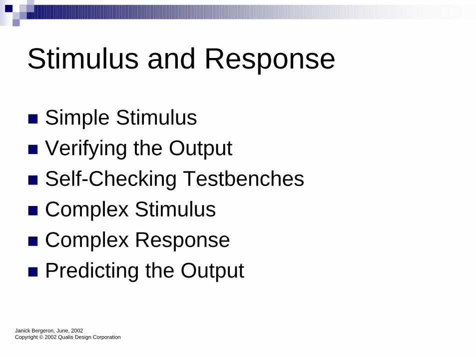
Stimulus and Response
� Simple Stimulus� Verifying the Output� Self-Checking Testbenches� Complex Stimulus� Complex Response� Predicting the Output
Janick Bergeron, June, 2002Copyright © 2002 Qualis Design Corporation

The Art of Verification
� Two simple questions
� Am I driving all possible input scenarios?
� How will I know when it fails?

Perfect VerificationTo fully verify a black box, you must show that the logic works correctly for all combinations of inputs.
This entails:�Driving all permutations on the input lines�Checking for proper results in all cases
Full verification is not practical on large pieces of designs...but the principles are valid across all verification.

In an Ideal World....� Every macro would have perfect verification performed
�All permutations would be verified based on legal inputs�All outputs checked on the small chunks of the design
� Unit, chip, and system level would then only need to verify interconnections�Ensure that designers used correct Input/Output
assumptions and protocols
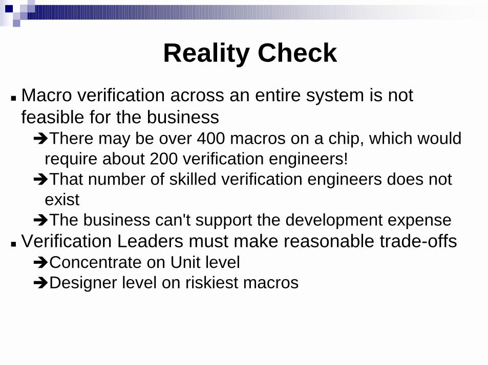
Reality Check� Macro verification across an entire system is not
feasible for the business�There may be over 400 macros on a chip, which would
require about 200 verification engineers!�That number of skilled verification engineers does not
exist�The business can't support the development expense
� Verification Leaders must make reasonable trade-offs�Concentrate on Unit level�Designer level on riskiest macros

Simple Stimulus
� Generating Stimulus is the process of providing input signals to the DUV
� Every input to the DUV is an output from a stimulus model
� Any deterministic waveform is easy to generate
Janick Bergeron, June, 2002Copyright © 2002 Qualis Design Corporation

Simple Stimulus (Cont) –Complex Waveforms � Complex waveforms
�Care must be taken not to over constrain the waveform generation or limit it to a subset of its possible variations.
�Need to make sure that there are many instances of absolute min and max values� Controlled Randomization
Janick Bergeron, June, 2002Copyright © 2002 Qualis Design Corporation
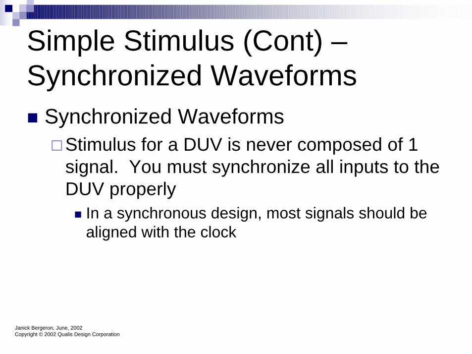
Simple Stimulus (Cont) –Synchronized Waveforms� Synchronized Waveforms
�Stimulus for a DUV is never composed of 1 signal. You must synchronize all inputs to the DUV properly� In a synchronous design, most signals should be
aligned with the clock
Janick Bergeron, June, 2002Copyright © 2002 Qualis Design Corporation
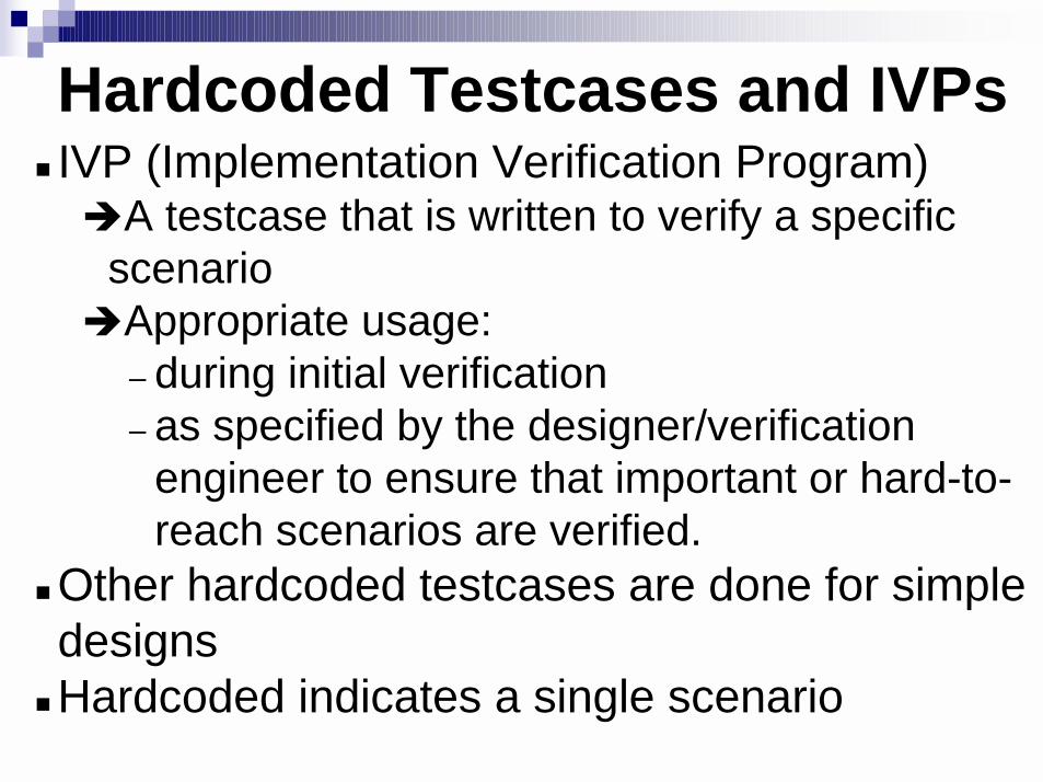
Hardcoded Testcases and IVPs� IVP (Implementation Verification Program)
�A testcase that is written to verify a specific scenario
�Appropriate usage:– during initial verification – as specified by the designer/verification
engineer to ensure that important or hard-to-reach scenarios are verified.
� Other hardcoded testcases are done for simple designs
� Hardcoded indicates a single scenario

Verifying the Output
� Generating Stimulus is only about 30% of job, 70% is in verifying output
� Most obvious method is visually�ASCII output�Waveforms
Janick Bergeron, June, 2002Copyright © 2002 Qualis Design Corporation
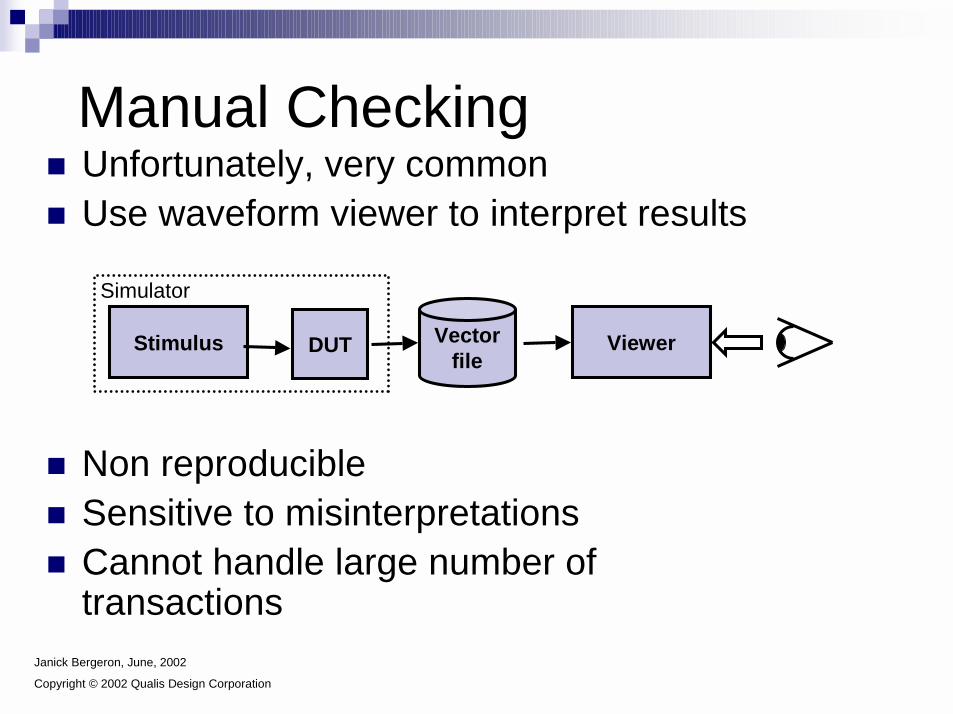
� Unfortunately, very common� Use waveform viewer to interpret results
� Non reproducible� Sensitive to misinterpretations� Cannot handle large number of
transactions
Manual Checking
Stimulus DUT Vectorfile
Simulator
Viewer
Janick Bergeron, June, 2002
Copyright © 2002 Qualis Design Corporation

Producing Simulation Results
� Which signals are significant change with time� In order to determine what is correct, must
model this knowledge� Producing the proper simulation results involves
modeling the behavior of the signal sampling� Sample at regular intervals (clk)� Sample on interested signals (only when they
change)
Janick Bergeron, June, 2002Copyright © 2002 Qualis Design Corporation

Visual Inspection of Waveforms
� Results are better (to understand) when plotted over time�Advantage is that it plots the signal
continuously overtime, not at specified points as in text view (the samples)
�Tool dependent on how to turn on�Performance impact, want to minimize the
total number of signals to view�Mostly used for debug
Janick Bergeron, June, 2002Copyright © 2002 Qualis Design Corporation

Self-Checking Testbenches
� Use self-checking – different techniques�Specify input and expected output for each
clock cycle� Problems
� Difficult to maintain� Difficult to specify� Difficult to debug� Require perfectly synchronous interfaces
Janick Bergeron, June, 2002Copyright © 2002 Qualis Design Corporation
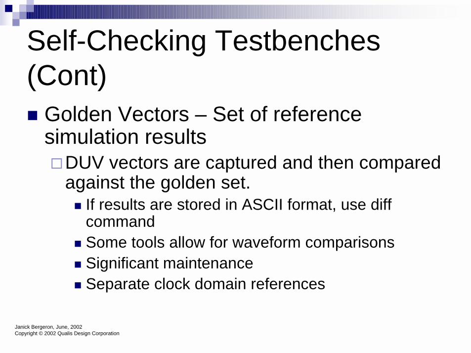
Self-Checking Testbenches (Cont)� Golden Vectors – Set of reference
simulation results�DUV vectors are captured and then compared
against the golden set.� If results are stored in ASCII format, use diff
command� Some tools allow for waveform comparisons� Significant maintenance� Separate clock domain references
Janick Bergeron, June, 2002Copyright © 2002 Qualis Design Corporation

Golden Vectors� Natural extension of DFT & visual check� Compare results against known good
results
Stimulus Vectorfile
Simulator
Viewer
Vectorfile
Comparator
DUT
Janick Bergeron, June, 2002
Copyright © 2002 Qualis Design Corporation
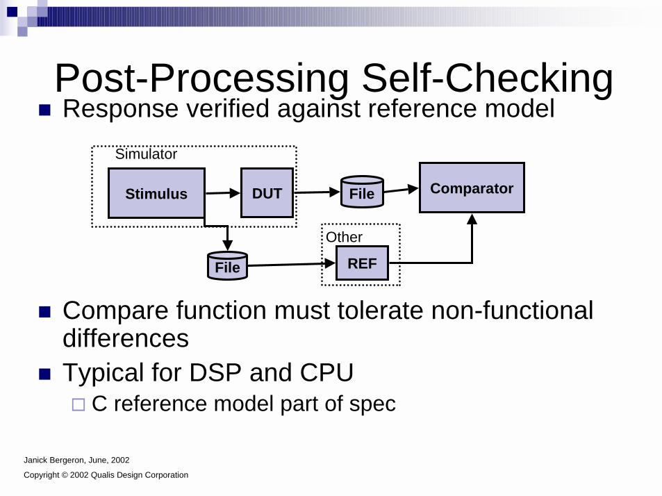
� Response verified against reference model
� Compare function must tolerate non-functional differences
� Typical for DSP and CPU� C reference model part of spec
Post-Processing Self-Checking
File
Simulator
File
ComparatorStimulus DUT
REF
Other
Janick Bergeron, June, 2002
Copyright © 2002 Qualis Design Corporation

Self-Checking Testbenches (Cont)� Run-Time Result Verification
�Results compared in parallel with the stimulus generation� Use a reference model
� The DUV and reference model are subjected to same stimulus
� Outputs of both, DUV and reference model, are constantly monitored and compared.
Janick Bergeron, June, 2002Copyright © 2002 Qualis Design Corporation

Reference Model� Abstraction of design implementation� Could be a
�complete behavior description of the design using a standard programming language
�formal specification using math. languages�complete state transition graph�detailed testplan in the english language for
handwritten testpattern�part of a random driver or checker�....
Self-Checking Testbenches (Cont)� Focus on operations instead of input and
output vectors� Include the verification of the operations that
were put into the subprograms.� Instead of simply applying stimulus, include
the checking, now just run the operations, individually or in sequence.
� Must verify that the operations are being performed.
Janick Bergeron, June, 2002Copyright © 2002 Qualis Design Corporation
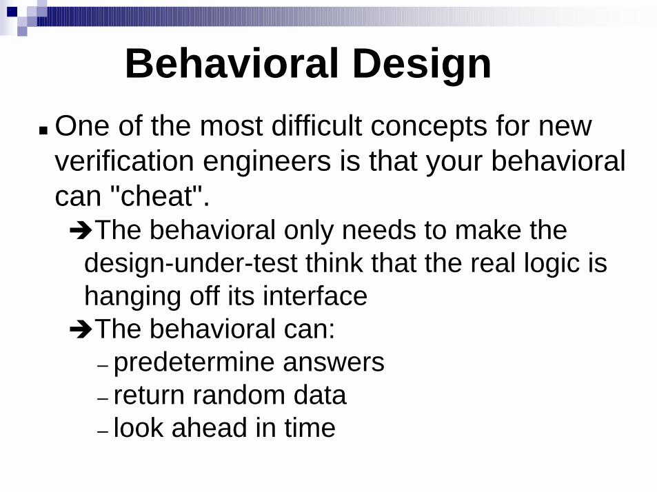
Behavioral Design� One of the most difficult concepts for new
verification engineers is that your behavioral can "cheat".�The behavioral only needs to make the
design-under-test think that the real logic is hanging off its interface
�The behavioral can:– predetermine answers– return random data– look ahead in time

Behavioral Design� Cheating examples
�Return random data in Memory modeling– A memory controller does not know what data
was stored into the memory cards (behavioral). Therefore, upon fetching the data back, the memory behavioral can return random data.
�Branch prediction– A behavioral can look ahead in the instruction
stream and know which way a branch will be resolved. This can halve the required work of a behavioral!

Complex Stimulus
� Talked about simple stimulus� Complex stimulus includes feedback from
DUV to the stimulator� Most desirable is a bus-functional model
that is configurable.
Janick Bergeron, June, 2002Copyright © 2002 Qualis Design Corporation
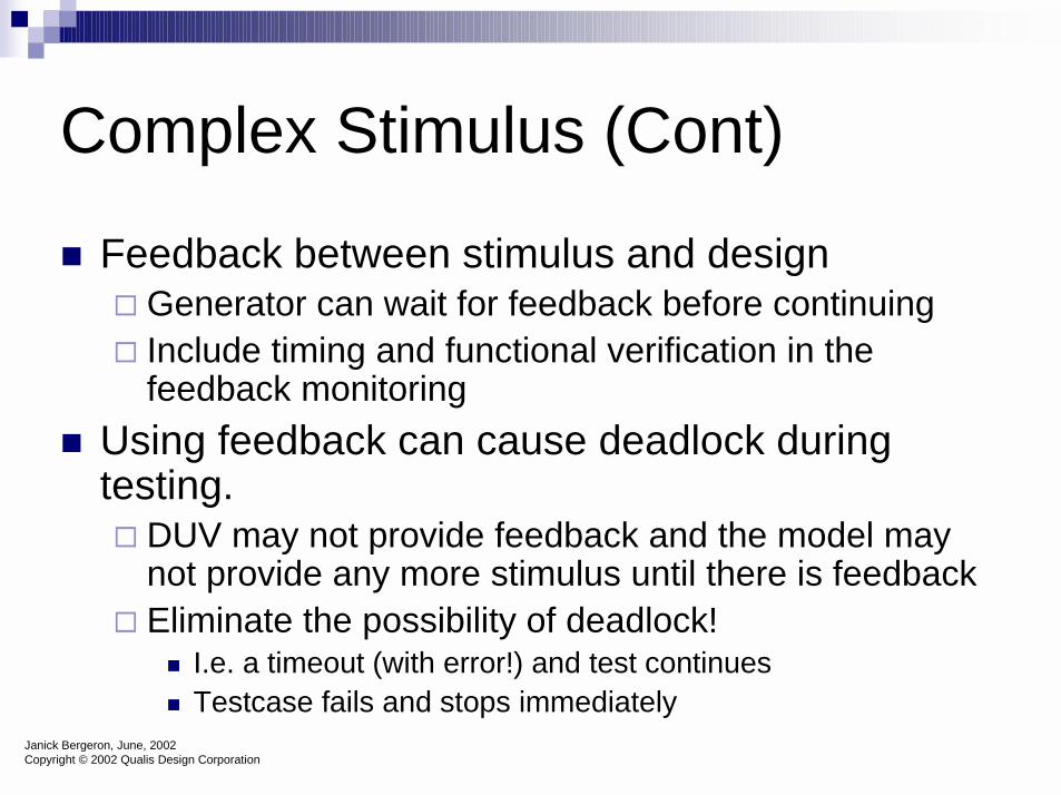
Complex Stimulus (Cont)
� Feedback between stimulus and design� Generator can wait for feedback before continuing � Include timing and functional verification in the
feedback monitoring� Using feedback can cause deadlock during
testing.� DUV may not provide feedback and the model may
not provide any more stimulus until there is feedback� Eliminate the possibility of deadlock!
� I.e. a timeout (with error!) and test continues� Testcase fails and stops immediately
Janick Bergeron, June, 2002Copyright © 2002 Qualis Design Corporation

Complex Response
� We identified that visual inspection is not the way to go. And that was with simple responses, what about complex responses.�Must automate this, one way to perform this is
with BFM’s�What is a complex response?
Janick Bergeron, June, 2002Copyright © 2002 Qualis Design Corporation
Complex Response – (Cont)
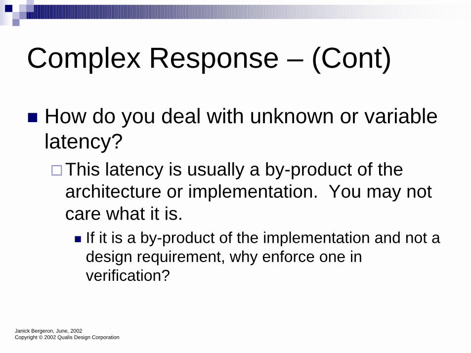
� How do you deal with unknown or variable latency?�This latency is usually a by-product of the
architecture or implementation. You may not care what it is. � If it is a by-product of the implementation and not a
design requirement, why enforce one in verification?
Janick Bergeron, June, 2002Copyright © 2002 Qualis Design Corporation

Complex Response – (Cont)
� Earlier we encapsulated input operations – can do the same for outputs� For stimulus, the subprograms took the arguments as
stimulus. � For output operations, take the arguments as the
expect results (results that the DUV should output)� Implementation should be as configurable as the
stimulus.� Remember – consider all possible failure
modes.
Janick Bergeron, June, 2002Copyright © 2002 Qualis Design Corporation
Complex Response – (Cont)
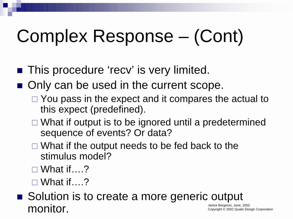
� This procedure ‘recv’ is very limited.� Only can be used in the current scope.
� You pass in the expect and it compares the actual to this expect (predefined).
� What if output is to be ignored until a predetermined sequence of events? Or data?
� What if the output needs to be fed back to the stimulus model?
� What if….?� What if….?
� Solution is to create a more generic output monitor. Janick Bergeron, June, 2002
Copyright © 2002 Qualis Design Corporation

Complex Response – (Cont)
� Generic Output monitor:� Return the data that the DUV output back to the
caller!� The ‘higher authority’ now makes the call to what is correct
and what is not. It is also controlling the stimulus model, therefore it knows more of the state of the environment and what is to be tested.
� The other things (protocols, etc) are still be verified.� But do not arbitrarily constrain the input.
Janick Bergeron, June, 2002Copyright © 2002 Qualis Design Corporation

Complex Response – (Cont)
� Monitoring multiple possible operations�You may have a situation where more than
one type of output may be OK. (branch prediction, out of order processing, etc)� Can’t predict unless you model the details of
implementation.� If you verify for a particular order, over constraining
environment (starting directed tests).
Janick Bergeron, June, 2002Copyright © 2002 Qualis Design Corporation

Complex Response – (Cont)
� We defined a stimulator as one who has outputs. If a monitor must provide output back to the DUV, is it not a stimulator?�Stimulator (or generator) is a model that
initiates a transaction�Monitor is a model that may/many not
respond to an operation initiated by the DUV.
Janick Bergeron, June, 2002Copyright © 2002 Qualis Design Corporation

Typical Verification diagram
DUT(Calculator)
Protocol
Packet
Sequence
Conv-ersation Errors
Struct:HeaderPayloadchecking
gen packetdrive packetpost packet
Bus
Scoreboardxlate
predict
Checking framework
Stimulustypeslatencyaddresssequences
DeviceFSMsconditionstransactionstransitions
Coverage Data

Traditional Approach� Self-checking not a requirement� Used with HDLs, or C/C++� Large number of testbenches� Progress measured against check-list
Time
% T
estc
ases
Goal
Janick Bergeron, June, 2002
Copyright © 2002 Qualis Design Corporation

Random Approach
� Progress measured using functional coverage metrics
Time
% T
estc
ases
Goal
Self-checking, random test environment
development time
Self-checking, random test environment
development time
Janick Bergeron, June, 2002
Copyright © 2002 Qualis Design Corporation

Random Vs Traditional
Time
% T
estc
ases
Goal
Productivitygain
Productivitygain
Janick Bergeron, June, 2002
Copyright © 2002 Qualis Design Corporation

The Line Delete EscapeThe Line Delete Escape
� Escape: A problem that is found on the test floor (after fabrication) and therefore has escaped the verification process
� The Line Delete escape was a problem on the ES/9000 machine � S/390 Bipolar, 1991� Escape shows example of how a verification
engineer needs to think
The Line Delete EscapeThe Line Delete Escape(pg 2)(pg 2)
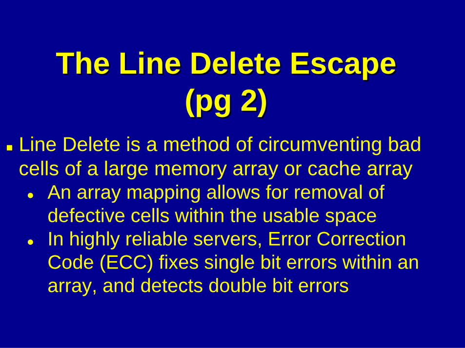
� Line Delete is a method of circumventing bad cells of a large memory array or cache array� An array mapping allows for removal of
defective cells within the usable space� In highly reliable servers, Error Correction
Code (ECC) fixes single bit errors within an array, and detects double bit errors

The Line Delete EscapeThe Line Delete Escape(pg(pg 3)3)
If a line in an array has multiple bad bits (a single bit usually goes unnoticed due to ECC-error correction codes), the line can be taken "out of service".In the array pictured, row 05 has a bad congruence class entry.
.
.
.
05

The Line Delete EscapeThe Line Delete Escape(pg 4)(pg 4)
Data enters ECC creation logic prior to storage into the array. When read out, the ECC logic corrects single bit errors and tags Uncorrectable Errors (UEs), and increments a counter corresponding to the row and congruence class.
.
.
.
05
Data in
ECC Logic Counters
ECC Logic
Data out

The Line Delete EscapeThe Line Delete Escape(pg 5)(pg 5)
When a preset threshhold of UEs is detected from a array cell, the service controller is informed that a line delete operation is needed.
.
.
.
05
Data in
ECC Logic Counters
ECC Logic
Data outThreshhold
Service Controller
The Line Delete EscapeThe Line Delete Escape(pg 6)(pg 6)
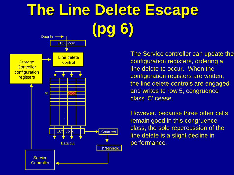
The Service controller can update the configuration registers, ordering a line delete to occur. When the configuration registers are written, the line delete controls are engaged and writes to row 5, congruence class 'C' cease.
However, because three other cells remain good in this congruence class, the sole repercussion of the line delete is a slight decline in performance.
.
.
.
05
ECC Logic Counters
Data in
ECC Logic
Data outThreshhold
Service Controller
Line delete controlStorage
Controller configuration
registers

The Line Delete EscapeThe Line Delete Escape(pg 7)(pg 7)
.
.
.
05
ECC Logic Counters
Data in
ECC Logic
Data outThreshhold
Service Controller
Line delete controlStorage
Controller configuration
registersHow would we test this logic?
What must occur in the testcase?What checking must we implement?