stirling engines a brief review of loaded hot air piston engine revolution 90 stirling engines a...
TRANSCRIPT
The Piston Engine Revolution
90
Stirling Engines A brief review of loaded hot air Derek Duffett The Waterworks Museum, Hereford
This paper reviews the development of the Stirling engine in an attempt to give it a logical place in the development of devices designed to produce mechanical work from heat. The action of hot air engines is examined and the principle of the Stirling Engine in particular is presented. The capabilities of the Stirling engine are discussed together with the benefits and limitations of their use.
A short history of the manufacture and uses of Stirling engines is presented and some examples of prospective applications considered. KEYWORDS: Hot Air Engine, Stirling Engine
Introduction
Next to perpetual motion machines, the hot air engine has intrigued the inventive mind most since there is something primordial about it. It appeals to critical thinking concerning the relationship between heat and work and tempts one to juggle with a few basic parameters to conjure optimum solutions.
This paper outlines the development of hot air engines by putting them into an historical context which shows why they were developed and gained popularity and how demand for them was influenced by their capabilities and limitations. The paper will outline some of the competitive developments in other areas of engineering which eventually led to their decline and tell how needs which arose in the twentieth century prompted a renewed interest in their possibilities. Finally, the paper will give some indication of their prospects to meet new market needs and how they could play a very much more significant role in the future. Early developments in heat engines It is not known for certain when it was realised that useful mechanical work could be derived from heat, but Hero’s aeolipile or the device he describes for secretly opening temple doors must be discounted, unless, that is of course, the power to amuse or inspire superstitious wonder is given any value. No, by useful mechanical work is that which describes the desired movement of a mass from A to B within a required timescale, especially that which is beyond normal human physical capability. In other words work which needs to be done at a certain rate and which nobody either can or wants to do.
The Piston Engine Revolution
91
We do know that one of the primary needs for useful mechanical work was raising water: firstly for irrigation or drinking purposes and later to keep mines from flooding. Although the requirement for irrigation could be met using human, animal, wind or waterpower, the emptying of mines was a rather different matter. It is not surprising therefore, that the pressing need to drain mines of water encouraged the invention and development of fuel powered engines for pumps.
Two of the best-known physical effects of heat on a substance were that it expanded and/or changed state. In particular, the expansive properties of steam, when heated, were well known and documented by the end of the seventeenth century. The challenge was to harness this property so that useful work could be done.
The first successful attempt to do this on any effective scale was the Savery pump, which was an arrangement not dissimilar to a pulsometer pump, but manually operated. This used steam, firstly to create a vacuum in a closed vessel so as to suck water up from a sump and then, following some opening and closing of valves, to expel that water, under the pressure of freshly introduced steam, up a pipe to the level required. The only thing that moved in this pump, apart from the opening and closing of valves, was the steam and the water being pumped. Leaving aside its inherent inefficiency it seemed ideal, but suffered some serious drawbacks. It could only raise water by vacuum up to a maximum of 32 feet (9.75m) theoretically, but in practice only c.20 feet (6.1m). To go higher it had to use whatever pressure the boiler could withstand.
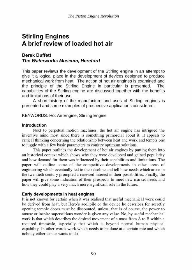
Furthermore, the boiler had to be close to the ‘vacuum tank’ to minimise heat losses, and very often this meant it had to be located deep inside the mineshaft to be drained. This made the situation intolerably hot and uncomfortable for the operators. In addition, frequent devastating boiler explosions due to poor technology and the temptation to raise the pressure so as to maximise the height to which water could be raised, ensured its rapid demise as soon as Newcomen’s piston engine came on the scene in 1712 (Figure 1).
Newcomen’s great innovation, the powered piston housed in its own special cylinder, translated the pressure created in the boiler into a force which could be expressed in a desired direction and applied at a chosen location to accomplish useful work. At a stroke, to use that expression, Newcomen enabled pump mechanisms to operate at pressures that were independent of those which contemporary boilers could withstand. Furthermore, since these pumps were mechanically coupled to the piston, they could be located at some distance from the boiler. For example, in the case of Cornish mines, pumps situated many hundreds of feet below ground level were powered by surface steam engines using safer boiler pressures. This greatly reduced the risk of explosion.
The Piston Engine Revolution
92
Scenario at the end of eighteenth century As a result of Newcomen’s invention, which some think was the single most important step taken in the history of mechanical engineering, the stationary steam engine became a practical proposition. During the next hundred years improvements in its design, particularly by James Watt, not only made it more efficient and economically attractive to meet some essential needs, but also created new market opportunities. Its use became widespread, particularly in this country, and in fact by the end of the eighteenth century there were around 2000 stationary steam engine installations.
Figure 1. Schematic of Newcomen Engine
Although important progress had been made, these were still early days and
to get this into perspective it is worth noting the estimated capacity of installed power generating equipment in Britain about this time as given in the table below.1
Table 1 Installed power sources at the end of the eighteenth century
Source of Power Horsepower ~kW Waterwheels: 120000 89500 Newcomen: 1454 engines (~5 HP) 24000 17900 Windmills: 15000 11200
The Piston Engine Revolution
93
Watt: 496 engines (5-10 HP) (including 24 blast furnaces/308 mills)
11200 8360
TOTAL 170200 126960 Although Watt resisted it, the desire to get more power from a given size of
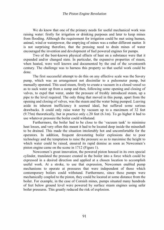
machine tempted manufacturers to produce engines which worked at the highest boiler pressure that they dared use. Bearing in mind the relatively primitive boiler design and technology, as exemplified by the haystack construction, this was quite a risky endeavour. Also, it must be remembered that about this time, Trevithick had started to develop his superior Cornish boiler, but this heralded even higher working boiler pressures 40psi (2.7 bar). As result, whether through poor design, manufacture, ignorance of the properties of the materials available, or poor operations and maintenance procedures, boiler explosions were not uncommon (Figure 2).
Figure 2. Effects of a Boiler Explosion
It was the devastating effects of such explosions which motivated the Rev
Robert Stirling (1790-1879) (Figure 3), with the help of his brother James, to develop a practical hot air engine which could be used safely by untrained staff without any fear of explosion. The inherent safety properties of a Hot Air Engine The reason why a hot air engine is able to operate more safely than a steam engine lies in the inherent difference between the expansive properties of water and air when heated.
There are two factors here that must be borne in mind. The first is that any substance which, when heated, can be converted from a solid or liquid into its gaseous form will undergo a much greater expansion than a substances which is
The Piston Engine Revolution
94
already in a gaseous form before its temperature is raised. The second concerns the degree to which the temperature can be conveniently raised. For the common forms of fuel then available i.e. wood or coal, upper temperatures which could be achieved by burning in air were, roughly speaking, 750ºC and 1400ºC respectively. The most commonly available material that is capable of making the transition from a liquid to a gas, from ‘room’ temperature up to these levels, is water.
Now, a unit volume of water when heated (and changing from liquid to gaseous phase) will create 1664 units by volume of dry saturated steam at atmospheric pressure, whereas air (already in its gaseous phase) will only expand according to Charles’s Law i.e. directly proportionally to its absolute temperature. For the temperatures quoted above, this is about 3 and 5 times.
Obviously, for a steam engine to perform useful work it must have access to a ready supply of working fluid, i.e. steam, capable of meeting the demands expected to be placed upon it. Although boilers can be designed to generate steam at an adequate rate, their response time to sudden demands is relatively long, (unless some type of flash boiler is employed). Therefore provision must be made to hold a sufficient amount of generated steam, under pressure and ready for use. The boiler fulfils this function and it is in this store of pent-up energy where the danger lies.
In contrast, the hot air engine does not store much more than one cylinderful of hot air. Not only may this be at a relatively low pressure, but more significantly, it is incapable of enormous expansion. Thus it is much safer to operate a hot air engine than work with steam. The process of getting work from hot air There are a number of ways to get work from hot air, including hot air turbines and hot air balloons, but I shall concentrate on the process considered by Stirling. I shall not delve into the mathematics or use P-V or Temperature-Entropy diagrams since there are plenty of textbooks on the subject.
Imagine an enclosed mass of air at room temperature. Heat is applied at a certain temperature and expansion will take place according to Charles’s Law. That is, unless the mass of air is constrained, it will expand to occupy a volume that is directly proportional to its new absolute temperature. However, if it is constrained, then its pressure will rise and if this can be harnessed, work can be extracted until the differential pressure is reduced to zero. No further expansion will take place once the temperature of the air reaches the temperature of the heat source. No amount of extra heating, at that temperature, will result in any further expansion and thus no more work will be done. To obtain more work without raising the temperature even further, either the hot air has to be exhausted and replaced by a fresh supply of cold air or the hot air has to be cooled down so that the process can start all over again.
The Piston Engine Revolution
95
The amount of power derivable from the above process depends on the mass of air to be heated, the temperature of the air prior to heating, the temperature to which it is raised and on the rate at which the air can absorb the heat. This last point must not be forgotten. Since an infinitely large closed mass of air is out of the question, some sort of arrangement becomes necessary which produces work cyclically either by expanding and exhausting a finite mass of air, or expanding and contracting the same mass of air by heating and cooling it. The basic hot air engine Apart from a means of heating and cooling an enclosed mass of air, the type of hot air engine, under consideration by Stirling, had components which performed two basic functions. Firstly, a means to harness the power produced during the expansion/contraction process and secondly, a means to move the enclosed mass of air, once it had been heated and expanded, to a cooler part of the system so that it could be cooled and contracted ready for another heating phase.
In order to deliver the power produced, Stirling’s machine used a piston in a cylinder to transmit the force created to a crankshaft and flywheel. It should be noted that for a closed system during the heating phase, a pressure is developed on the piston only so long as the volume of the closed system is less than that required by the air for expansion at constant pressure. That is, the heated air must be trying to expand faster than the piston is moving out for a positive outward pressure to develop on the piston. Conversely, during the cooling phase the air contracts and, if the piston does not keep up with the contraction, it will be subject to an external atmospheric pressure pushing the piston in. Thus power is not only produced during the expansion phase, but is also produced during the contraction phase. Power from the contraction phase is not unlike that produced in early steam engines when steam was condensed and atmospheric pressure moved the piston in.
Textbooks on Stirling engines often refer to the inward motion of the piston as the compression phase. Compression will only occur if the momentum of the flywheel is moving the piston in before the air has had time to contract properly. Thus the opportunity to extract work from the engine whilst this happens is forfeited. Perhaps this is a reflection of the practical difficulties encountered when trying to achieve a rapid cooling of the air. However, one cannot wait for ever to extract the last joule of work from the engine during the final parts of either the heating or cooling phases since this would reduce the rate at which work and hence power is produced.
A theoretical analysis of the power capability of the machine is complex. Although the temperatures of the hot source and cold sink can be measured and the instantaneous volume of the enclosed air easily determined from the mechanical arrangements, the pressure within the volume of the air at any instant is not uniformly distributed. To complicate matters, the thermal equivalent circuit also
The Piston Engine Revolution
96
varies throughout the cycle due to the mechanical motions of the machine and the swirling of the air within it.
In common with many engineering practices at that time, before a better theoretical understanding had been developed, there was a huge amount of trial and error in attempting to optimise performance.
Early development of the Hot Air Engine The concept of Hot Air engines was not new when Stirling put his mind to it. In fact, the earliest mention was in 1699 by Guillaume Amontons and later (1759) by Rev Henry Wood vicar of High Ercall in Shropshire and Thomas Meade, a Yorkshire engineer from Sculcoats. But it was Sir George Cayley the famous pioneer of heavier-than-air flying machines who was first recorded as making a workable machine around 1807.
Sir George’s machine was an open cycle machine, that is, it exhausted the air once heated into the atmosphere. Unfortunately, it was not a practical proposition since the piston, which was made of copper, was not airtight.
The Rev Robert Stirling not only used his ingenuity to overcome the problem of producing an airtight piston, but also introduced what has become recognised as the key to acceptable efficiency and that is the ‘regenerator’ or ‘economiser’ as he called it. This device was placed between the hot and cold sections of the machine. Its purpose was to extract the heat from the air as it passed from the hot to the cold part of the machine, and then return the heat to the cold air as it returned to be reheated during the ‘power’ stroke. Since its earliest days, the improvement in efficiency has been attributed to the conservation of heat by the ‘economiser’. This may have appealed to Scottish instincts, but I suggest the time has come set the record straight and acknowledge the real reason why the ‘economiser’ worked. This was that it accelerated the cooling and heating processes which led to an increase in the machine’s power output performance. Thus the efficiency of the machine was improved, not by conserving heat, but by delivering more power output from the heat already supplied.
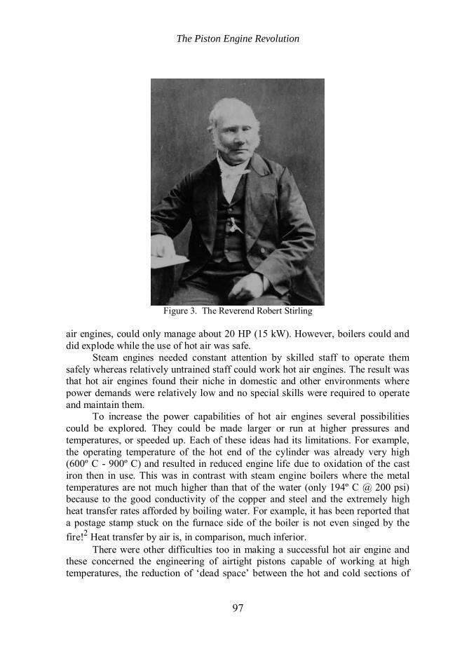
Following Stirling’s 1816 patent for ‘Improvements for diminishing the consumption of fuel and in particular an engine capable of being applied to the moving machinery on a principle entirely new’, practical machines began to be produced and in 1818 an engine was installed at a quarry in Scotland. Figure 3 shows a picture of Robert Stirling in his old age. Steam v Hot Air Engine Thus, by the second decade of the nineteenth century there were two classes of fuel-powered engines capable of providing motive power: the steam engine and the hot air engine. Each had its advantages and limitations. For example, the steam engine was capable of delivering power perhaps up to 100 HP (75 kW) whereas hot
The Piston Engine Revolution
97
Figure 3. The Reverend Robert Stirling
air engines, could only manage about 20 HP (15 kW). However, boilers could and did explode while the use of hot air was safe.
Steam engines needed constant attention by skilled staff to operate them safely whereas relatively untrained staff could work hot air engines. The result was that hot air engines found their niche in domestic and other environments where power demands were relatively low and no special skills were required to operate and maintain them.
To increase the power capabilities of hot air engines several possibilities could be explored. They could be made larger or run at higher pressures and temperatures, or speeded up. Each of these ideas had its limitations. For example, the operating temperature of the hot end of the cylinder was already very high (600º C - 900º C) and resulted in reduced engine life due to oxidation of the cast iron then in use. This was in contrast with steam engine boilers where the metal temperatures are not much higher than that of the water (only 194º C @ 200 psi) because to the good conductivity of the copper and steel and the extremely high heat transfer rates afforded by boiling water. For example, it has been reported that a postage stamp stuck on the furnace side of the boiler is not even singed by the fire!2 Heat transfer by air is, in comparison, much inferior.
There were other difficulties too in making a successful hot air engine and these concerned the engineering of airtight pistons capable of working at high temperatures, the reduction of ‘dead space’ between the hot and cold sections of
The Piston Engine Revolution
98
the engine, which reduced compression ratios, and the realisation of an efficient ‘regenerator’. Evolution of the Hot Air Engine Robert Stirling eventually, in partnership with his brother James, produced a hot air engine for his brother’s foundry in Dundee. In 1843 this was the most powerful hot air engine yet, being a double acting pressurised engine having 16 inch pistons with a 4ft stroke and developing 50 IHP (~37kW).3 However the hot end of the cylinder was still prone to corrosion and, after 3 replacements in 4 years, the engine was abandoned in favour of a steam engine.
Robert Stirling was not the only one to put his mind to the virtues of using air as an expansive medium to obtain work from heat.
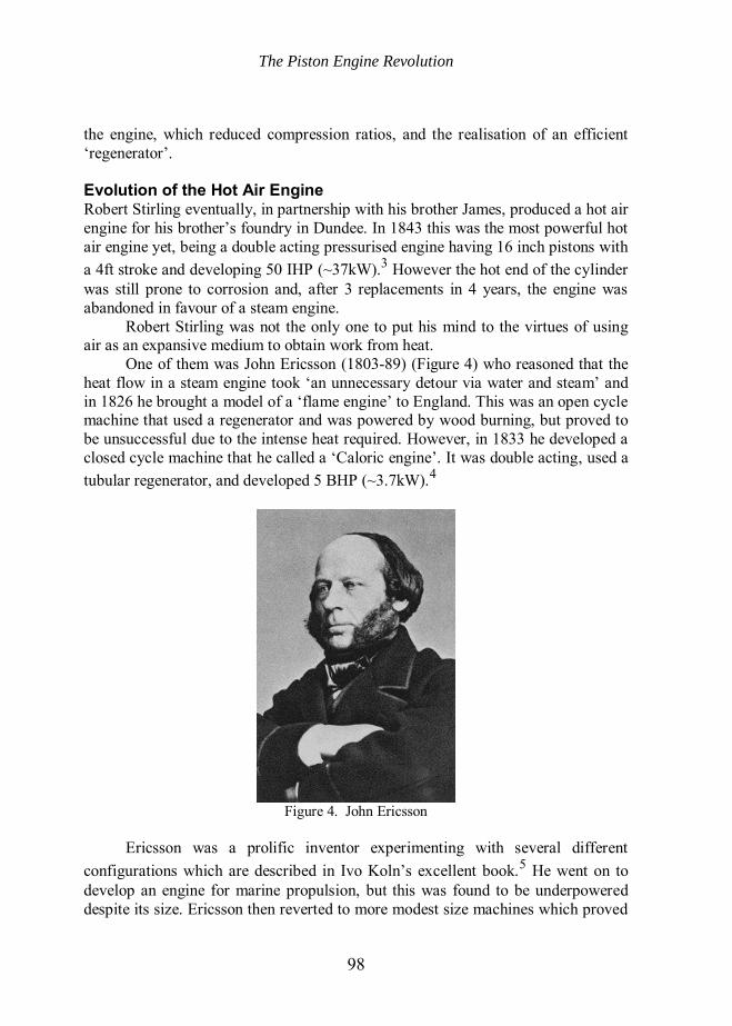
One of them was John Ericsson (1803-89) (Figure 4) who reasoned that the heat flow in a steam engine took ‘an unnecessary detour via water and steam’ and in 1826 he brought a model of a ‘flame engine’ to England. This was an open cycle machine that used a regenerator and was powered by wood burning, but proved to be unsuccessful due to the intense heat required. However, in 1833 he developed a closed cycle machine that he called a ‘Caloric engine’. It was double acting, used a tubular regenerator, and developed 5 BHP (~3.7kW).4
Figure 4. John Ericsson
Ericsson was a prolific inventor experimenting with several different
configurations which are described in Ivo Koln’s excellent book.5 He went on to develop an engine for marine propulsion, but this was found to be underpowered despite its size. Ericsson then reverted to more modest size machines which proved
The Piston Engine Revolution
99
to be much more successful, being made under licence by 10 companies in both the USA and Europe.
The variety of hot air engines developed during the 1800s showed that engineers in the UK, America and Europe were assiduous in exploring any new possibility that could overcome the difficulties mentioned earlier and many imaginative efforts went into solving these problems. These led to an assortment of early designs. The main ones have been subsequently classified as ‘alpha’, ‘beta’ and ‘gamma’ configurations whose main objective was to distance the piston and piston/displacer rod seals from the hot end of the cylinder.6
The Rider- Ericsson Partnership
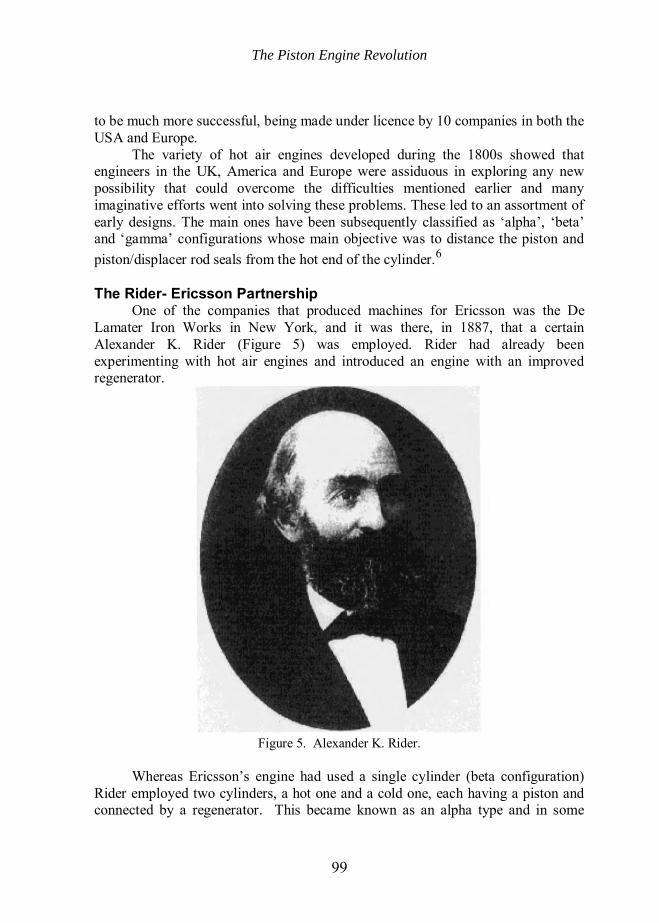
One of the companies that produced machines for Ericsson was the De Lamater Iron Works in New York, and it was there, in 1887, that a certain Alexander K. Rider (Figure 5) was employed. Rider had already been experimenting with hot air engines and introduced an engine with an improved regenerator.
Figure 5. Alexander K. Rider.
Whereas Ericsson’s engine had used a single cylinder (beta configuration)
Rider employed two cylinders, a hot one and a cold one, each having a piston and connected by a regenerator. This became known as an alpha type and in some
The Piston Engine Revolution
100
ways echoes the move made by Watt when he separated the condenser from the working cylinder.
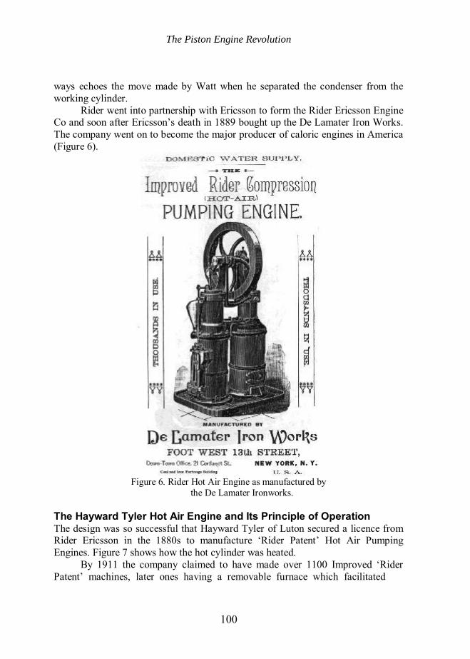
Rider went into partnership with Ericsson to form the Rider Ericsson Engine Co and soon after Ericsson’s death in 1889 bought up the De Lamater Iron Works. The company went on to become the major producer of caloric engines in America (Figure 6).
Figure 6. Rider Hot Air Engine as manufactured by
the De Lamater Ironworks.
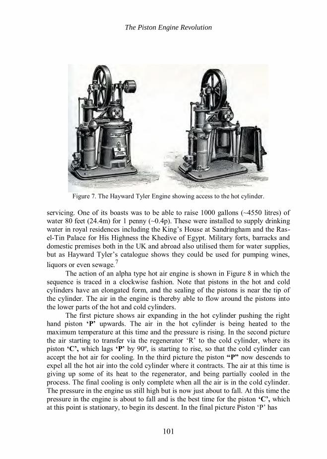
The Hayward Tyler Hot Air Engine and Its Principle of Operation The design was so successful that Hayward Tyler of Luton secured a licence from Rider Ericsson in the 1880s to manufacture ‘Rider Patent’ Hot Air Pumping Engines. Figure 7 shows how the hot cylinder was heated.
By 1911 the company claimed to have made over 1100 Improved ‘Rider Patent’ machines, later ones having a removable furnace which facilitated
The Piston Engine Revolution
101
Figure 7. The Hayward Tyler Engine showing access to the hot cylinder.
servicing. One of its boasts was to be able to raise 1000 gallons (~4550 litres) of water 80 feet (24.4m) for 1 penny (~0.4p). These were installed to supply drinking water in royal residences including the King’s House at Sandringham and the Ras-el-Tin Palace for His Highness the Khedive of Egypt. Military forts, barracks and domestic premises both in the UK and abroad also utilised them for water supplies, but as Hayward Tyler’s catalogue shows they could be used for pumping wines, liquors or even sewage.7
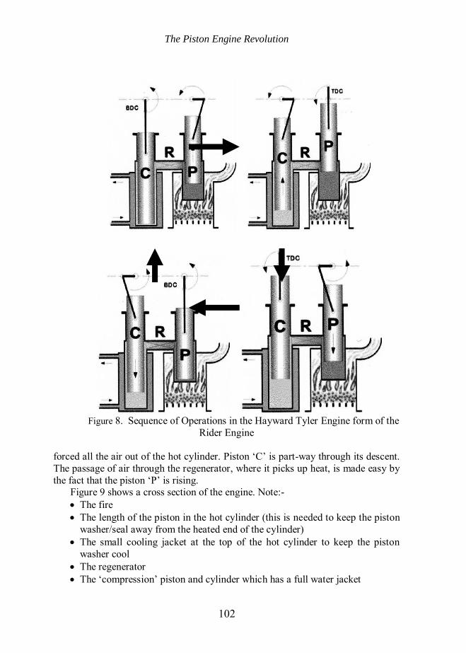
The action of an alpha type hot air engine is shown in Figure 8 in which the sequence is traced in a clockwise fashion. Note that pistons in the hot and cold cylinders have an elongated form, and the sealing of the pistons is near the tip of the cylinder. The air in the engine is thereby able to flow around the pistons into the lower parts of the hot and cold cylinders.
The first picture shows air expanding in the hot cylinder pushing the right hand piston ‘P’ upwards. The air in the hot cylinder is being heated to the maximum temperature at this time and the pressure is rising. In the second picture the air starting to transfer via the regenerator ‘R’ to the cold cylinder, where its piston ‘C’, which lags ‘P’ by 90º, is starting to rise, so that the cold cylinder can accept the hot air for cooling. In the third picture the piston “P” now descends to expel all the hot air into the cold cylinder where it contracts. The air at this time is giving up some of its heat to the regenerator, and being partially cooled in the process. The final cooling is only complete when all the air is in the cold cylinder. The pressure in the engine us still high but is now just about to fall. At this time the pressure in the engine is about to fall and is the best time for the piston ‘C’, which at this point is stationary, to begin its descent. In the final picture Piston ‘P’ has
The Piston Engine Revolution
102
Figure 8. Sequence of Operations in the Hayward Tyler Engine form of the
Rider Engine
forced all the air out of the hot cylinder. Piston ‘C’ is part-way through its descent. The passage of air through the regenerator, where it picks up heat, is made easy by the fact that the piston ‘P’ is rising.
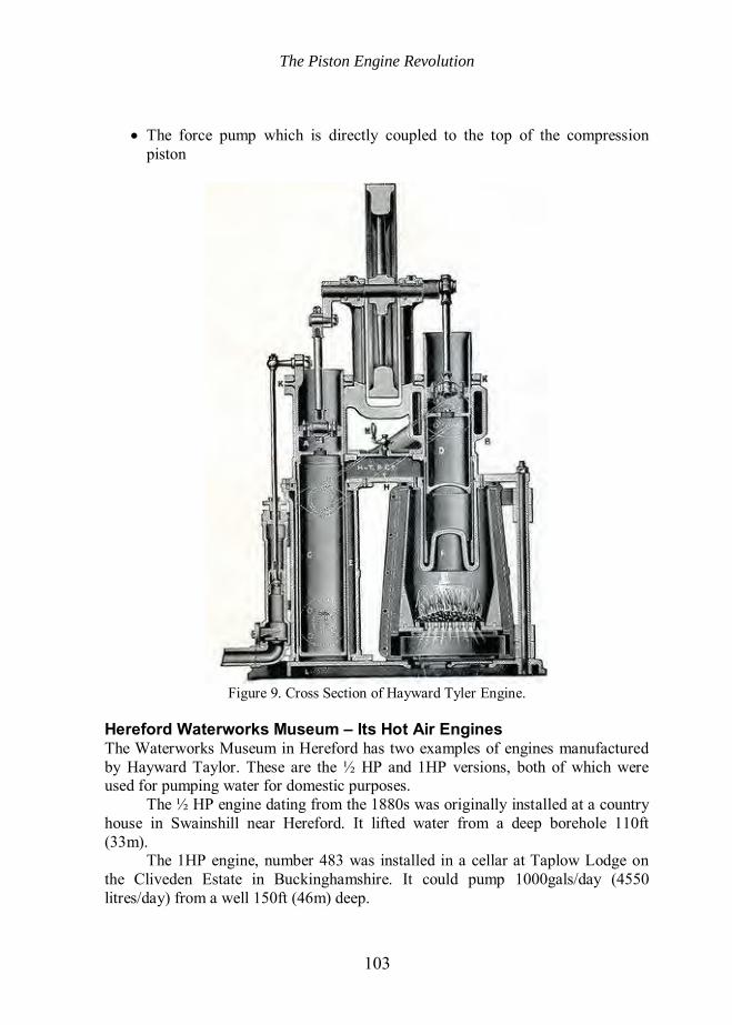
Figure 9 shows a cross section of the engine. Note:- The fire The length of the piston in the hot cylinder (this is needed to keep the piston
washer/seal away from the heated end of the cylinder) The small cooling jacket at the top of the hot cylinder to keep the piston
washer cool The regenerator The ‘compression’ piston and cylinder which has a full water jacket
The Piston Engine Revolution
103
The force pump which is directly coupled to the top of the compression piston
Figure 9. Cross Section of Hayward Tyler Engine.
Hereford Waterworks Museum – Its Hot Air Engines The Waterworks Museum in Hereford has two examples of engines manufactured by Hayward Taylor. These are the ½ HP and 1HP versions, both of which were used for pumping water for domestic purposes.
The ½ HP engine dating from the 1880s was originally installed at a country house in Swainshill near Hereford. It lifted water from a deep borehole 110ft (33m).
The 1HP engine, number 483 was installed in a cellar at Taplow Lodge on the Cliveden Estate in Buckinghamshire. It could pump 1000gals/day (4550 litres/day) from a well 150ft (46m) deep.

The Piston Engine Revolution
104
The Waterworks Museum in Hereford has produced a booklet and a DVD entitled ‘Hot-Air Engines’ which give the history and development of Stirling engines.8
Uses of Hot Air Engines
The popularity of hot air engines increased during the nineteenth century. This was largely due to their comparative safety and ease of operation, coupled with the relatively easy access to local supplies of a range of fuels, mainly wood, coal or coke, but basically anything that would burn.
As already seen, the most pressing need fulfilled by these machines was for pumping water for domestic and farm consumption. Although the municipal supply of piped potable water was beginning to emerge during the nineteenth century, in Britain it would take a long time to reach most rural areas. Thus, hot air engines were to be found in large country houses and farms to draw water from wells and other sources.
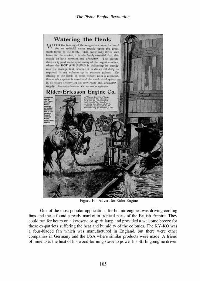
In America, following the great push west by the railways, large fenced ranches were created often without access to rivers or lakes which could be relied upon all the year round to supply water. Thus, it became essential to have some means of pumping water from underground sources. Although wind pumps were available, they were not much use when the wind did not blow! An advertisement for Rider Ericsson Engines extols their virtues (Figure 10). The engines could be quickly started and then safely left unattended to pump water to a storage header tank for use as required.
Later in the century developments in the technology of electric lighting made its application in lighthouses attractive, but a source of electricity was required and this had to be generated on the spot since there was no National Grid in those days. Not only were lights required, but around our fogbound coasts foghorns became a necessity and for these a supply of compressed air had to be created. For both of these applications the hot air engine was ideal particularly bearing in mind the remote locations in which lighthouses are often situated.
At the Lizard Lighthouse for example, Trinity House had two hot air engines installed in 1878. These provided the electricity for the arc lamps and the compressed air for the newly installed foghorns, possibly the Daboll Trumpet type adopted by the Trinity House Commissioners in 1863. These served for many years, but were eventually replaced by oil engines in 1895 and 1907.9
Another use for hot air engines was to power small machinery in workshops and other business premises including printing presses. Unlike steam engines, they did not require a police licence to operate a boiler.
A virtue of the closed system hot air engine, was that it was very quiet in operation and this made it ideal for church organ blowers. Its quietness is due to the fact that there is no exhaust noise or movement of valves.
The Piston Engine Revolution
105
Figure 10. Advert for Rider Engine
One of the most popular applications for hot air engines was driving cooling
fans and these found a ready market in tropical parts of the British Empire. They could run for hours on a kerosene or spirit lamp and provided a welcome breeze for those ex-patriots suffering the heat and humidity of the colonies. The KY-KO was a four-bladed fan which was manufactured in England, but there were other companies in Germany and the USA where similar products were made. A friend of mine uses the heat of his wood-burning stove to power his Stirling engine driven
The Piston Engine Revolution
106
fan to circulate the hot air, from above the stove, around his house during the winter.
Perhaps one of the least reported and widespread applications of hot air engines were their use in early telephone exchanges. Here there was a need to charge the batteries used to provide current for ringing the bells of local subscribers’ telephone apparatus. Again, it must be remembered that when these early exchanges were built during the late nineteenth century there were few local supplies of electricity.
It will be noticed that all of these applications were for steady working at constant speed. This suited Stirling engines because they cannot respond easily to sudden demands for more power since this would require either a means of injecting heat more quickly, or access to a reserve store of energy. Thus Stirling engines have not easily lent themselves to automobile applications although some attempts have been made.
All the successful hot air engines in service used the Stirling regenerator and this led to the universal adoption of the generic name Stirling engines, even for those which use gases other than air as a working medium. Competitive developments during the nineteenth century By the end of the nineteenth century, Stirling engines had found their niche in the market for relatively low power generation, particularly in domestic and low power workshop applications. However, two other developments were taking place which, eventually, were to displace the hot air engine from its established position.
One of these developments was the internal combustion engine employing pistons in cylinders. This was, perhaps, a natural direction to take since mechanically, they bore a strong resemblance to steam engines.
Internal combustion engines had the advantage of safe operation, relatively high efficiency and high power/volume ratios. Several different types appeared. The first to emerge was the gas engine and later diesel, kerosene and other oil-fuelled engines. Their ability to produce high specific power was due to the fact that the heat was generated exactly when required within the cylinder itself. The combustion gases did not just expand, but were created explosively from tiny amounts of fuel and thus the engines exhibited much higher compression ratios and consequent power outputs, for their size, than hot air engines. However, each of these engines needed its own source of special fuel and, since supply infrastructures were only just beginning to develop, widespread usage was inhibited. For instance, producer gas had to be generated on the spot for the National Gas engine that was used at the Ross-on-Wye water pumping station. Both the gas engine and the remains of the producer gas plant can be seen on display at the Waterworks Museum in Hereford.
The Piston Engine Revolution
107
The other major development which took place during this period was in the entirely new discipline of electrical engineering and concerned the development of electric motors.
It should be borne in mind that although Faraday had demonstrated elementary electro-magnetic rotation in 1821, it was not until several decades later that useful motors emerged. Here again, progress in application was no doubt inhibited by the unavailability of an adequate source of electricity, but in the last two decades of the century, distributed electricity supplies appeared, spurred on by the demand for the recently developed incandescent electric lighting. Once electrical supplies became available, the convenience of having a power source that could just be switched on without the lighting of fires or provision of fuel supplies, created its own demand.
These developments drastically reduced the market for hot air engines and by the start of WW1 very few new engines were being sold. However, many of those that were installed continued to carry out their function, but were eventually superseded by internal combustion engines or electric motors. New applications and later developments
The start of the twentieth century saw the emergence of new technologies including the rapid development of the wireless communication and electronics industries. In particular, the establishment of broadcasting created a widespread demand for wireless receiving sets.
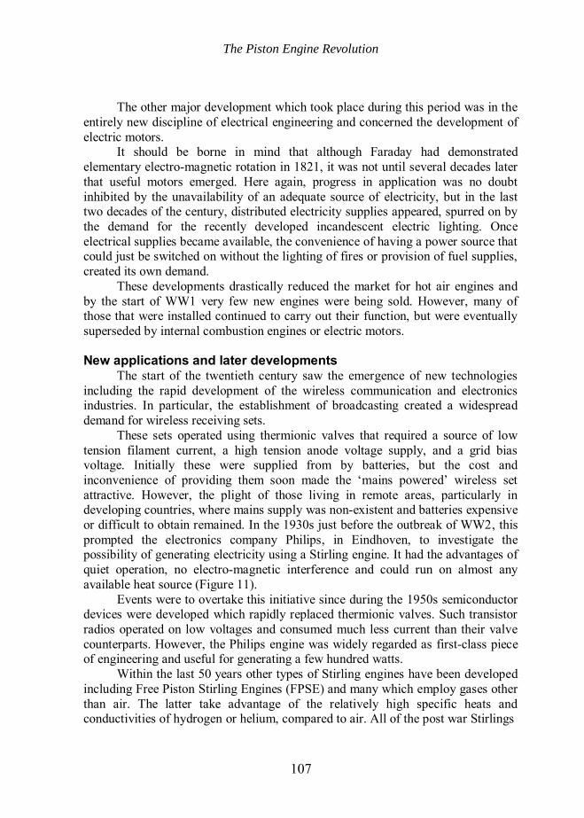
These sets operated using thermionic valves that required a source of low tension filament current, a high tension anode voltage supply, and a grid bias voltage. Initially these were supplied from by batteries, but the cost and inconvenience of providing them soon made the ‘mains powered’ wireless set attractive. However, the plight of those living in remote areas, particularly in developing countries, where mains supply was non-existent and batteries expensive or difficult to obtain remained. In the 1930s just before the outbreak of WW2, this prompted the electronics company Philips, in Eindhoven, to investigate the possibility of generating electricity using a Stirling engine. It had the advantages of quiet operation, no electro-magnetic interference and could run on almost any available heat source (Figure 11).
Events were to overtake this initiative since during the 1950s semiconductor devices were developed which rapidly replaced thermionic valves. Such transistor radios operated on low voltages and consumed much less current than their valve counterparts. However, the Philips engine was widely regarded as first-class piece of engineering and useful for generating a few hundred watts.
Within the last 50 years other types of Stirling engines have been developed including Free Piston Stirling Engines (FPSE) and many which employ gases other than air. The latter take advantage of the relatively high specific heats and conductivities of hydrogen or helium, compared to air. All of the post war Stirlings
The Piston Engine Revolution
108
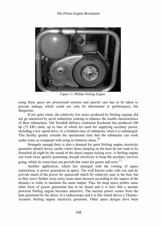
Figure 11. Phillips Stirling Engine.
using these gases are pressurised systems and special care has to be taken to prevent leakage which could not only be detrimental to performance, but dangerous.
If not quite silent, the relatively low noise produced by Stirling engines did not go unnoticed by naval authorities seeking to enhance the stealth characteristics of their submarines. The Swedish defence contractor Kockums has produced 100 hp (75 kW) units, up to four of which are used for supplying auxiliary power, including a low speed drive, to a Gotland class of submarine when it is submerged. This facility greatly extends the operational time that the submarine can work under water as compared with using its batteries alone.10
Strangely enough there is also a demand for quiet Stirling engine electricity generator aboard luxury yachts where those sleeping on the boat do not want to be disturbed all night by the sound of the diesel engine ticking over. A Stirling engine can work away quietly generating enough electricity to keep the auxiliary services going, whilst its waste heat can provide hot water for guests and crew.11
Another application, which has emerged with the coming of space exploration, is power generation in space. The well known solar cells can and do provide much of the power for spacecraft which fly relatively near to the Sun, but as they move further away array areas must increase according to the square of the distance in order to maintain the same output. Thus for deep space probes some other form of power generation has to be found and it is here that a nuclear powered Stirling engine becomes attractive. The nuclear power comes from the heat generated by the decay of a radioisotope and it is this which drives a Thermo-Acoustic Stirling engine electricity generator. Other space designs have been
The Piston Engine Revolution
109
proposed where the temperature differential between the hot part of the craft facing the Sun and the opposite cold side facing away from it provides the necessary conditions for operating the engine.
There are other, sometimes bizarre, applications for Stirling engines which can be found in the literature not forgetting a range of educational toys which excite curiosity and pose challenges. For example, I expect most of you will have seen engines which run on the heat of a cup of coffee or even those which will operate with the heat of a thumb.
All these engine designs have their place in the grand scheme of things, but perhaps the most important application which will assume greater significance as the twenty-first century progresses lies in the potential contribution Stirling engines could make in meeting electricity demand. Future scenario There are two avenues that are being pursued at present where it is claimed Stirling engines have the potential to play a significant role in providing cleaner greener electricity.
The first is to harness the sun’s power to provide the heat for a Stirling engine powered electricity generator.12 The basic unit consists of a mirror assembly capable of focussing the sun’s rays on to the hot end of a Stirling engine (FPSE). It is envisaged that there would be many such units linked together and covering a very large area of land. Obviously, such an arrangement would have to be sited where the sunshine can be relied upon and deserts naturally come to mind. It has been estimated that an area the size of Wales would be required to meet the needs of the UK.13 Here is not the place to discuss the enormous difficulties and attendant risks of implementing such a plan. It would clearly be a long-term venture, but does have the virtue that it draws upon a practically inexhaustible supply of clean energy.
The second avenue is to develop micro Combined Heat and Power (CHP) schemes where each domestic installation burns gas to heat a Stirling engine to generate electricity and uses the water boiler/central heating system to act as a heat sink.14 As it happens, two of the authors who have made contributions to this Conference on the Piston Engine Revolution, David Andrews and Fred Starr, were the two people in the UK who, back in 1987, got British Gas involved in the development of this concept. At the time there was much cynicism about the idea, but after many false starts, engines are now in production. Any excess electricity that the house cannot use can be exported into the grid for use elsewhere. Since this scheme utilises an existing infrastructure and can be retro-fitted, if desired, it is more likely to be adopted sooner than the solar scheme. It is recognised that natural gas supplies are finite, but that the lifetime of this scheme could be extended by the prospect of artificially produced gas or hydrogen.
The Piston Engine Revolution
110
Conclusion It is impossible in this short paper to be exhaustive or do justice to the enormous amount of time and effort devoted to the development and manufacture of hot air engines. The Rev Robert Stirling’s original intention was to produce an engine that could be used safely by unskilled people without fear of explosion. Whether this was altruism or recognition of a gap in the market, I cannot say, but surely he must have been gratified to see his key idea for a regenerator to be so universally adopted by manufacturers of hot air machines prior to his death in 1879. Siemens took up the regenerator principle in his own design of hot air engines, but more importantly, he used brick regenerators in the open-hearth steel furnace.
Whether Stirling foresaw the time when hot air engines would become redundant is a matter of conjecture, but I feel sure that he could not have foreseen the circumstances which have now led to a renaissance of his ideas and the serious attention which they now attract. Who knows, the World could be much more indebted to him than he ever could have imagined?
I hope this will encourage you to ponder the mysteries of the Stirling Engine and visit the Waterworks Museum to see two historic Stirling Engines actually working. Acknowledgements I am grateful to the Waterworks Museum, Hereford, for giving permission to use images for which they hold the copyright. Notes and References 1. Wikipedia ‘Steam Power during the Industrial Revolution” 2. C.A.M. Smith and A.G. Warren., A Handbook of Testing The Theory of Prime Movers (Constable, London, 1923), p. 282. 3. Smith, p. 126. 4. R. Darlington and K. Strong, Stirling and Hot Air Engines (The Crowood Press, 2005), p. 16. 5. I. Kolin, The Evolution of the Heat Engine (Moriya Press, 1998). 6. Darlington; Kolin; J.G. Rizzo, The Stirling Engine Manual (Camden Miniature Steam Services, 2005); J.R. Senft, An Introduction to Stirling Engines (Moriya Press, 2010). 7. Hot Air Engines Catalogue and Handbook produced by Hayward–Tyler & Co Ltd, 1911.
8. Hot Air Engines-The history of their development, how they work and the stories of their pioneering engineers; Hot Air Engines-Engines without boilers DVD (both from the Waterworks Museum – Hereford, 2009). 9. C. Rowe, Marconi at the Lizard (The Trevithick Society 2009), pp. 10 & 29. 10. B.H. Van Arsdell, Around the World by Stirling Engine (American Stirling Company 2003), p. 25. 11. Van Arsdell, p. 40. 12. M. Shelton, The Next Great Thing (W W Norton & Co, 1994). 13. D.J.C. MacKay, Sustainable Energy without the Hot Air (UIT Cambridge Ltd, 2009), p. 179. 14. F. Starr, ‘Power from the People’ Ingenia Online, Issue 8, p. 27.
Notes on Contributor After graduating from Queen Mary College, London University in 1958, Derek Duffett worked in research, marketing, and management in the electronics industry.
The Piston Engine Revolution
111
Following a short period in marketing with Ferranti Professional Components Department, Derek was invited, in 1982, to become Secretary of the Institution of Electronic and Radio Engineers (IERE) in London. Subsequent to the successful merger of the IERE with the Institution of Electrical Engineers (IEE) in 1988, he was appointed Director of the Association of Contract Electronics Manufacturers, which was then part of the Electronic Components Industry Federation.
After retiring in 1996 he moved to Hereford where he still plays an active rôle in the Hereford and Worcester Local Network of the Institution of Engineering and Technology (IET). Derek has become a Trustee and Hon Treasurer of the Waterworks Museum and may be contacted at: e-mail [email protected]