stm32-io-board - btcdl.btc.pl/kamami_wa/stm32-io-board.pdf · stm32-io-board data sheet 2 1 scope...
TRANSCRIPT

Data Sheet
STM32-IO-Board
Contents
Contents 1
1 Scope 2
2 Connections and Controls 2
3 Interfaces 4
4 Connecting the Board to the STM32-PerformanceStick 5
5 Technical Data 6
Rev. 11/2007 – 003
Windows®, Windows XP® and Windows Vista® are registered trademarks of the Microsoft corp. STM32 is a registered trademark of STMicroelectronics. Cortex is a registered trademark of ARM. All trademarks of other companies used in this document refer exclusively to the products of these companies.
Supported by Samtec www.samtec.com
STM32-IO-Board Data Sheet 2
1 Scope This data sheet is for the STM32-IO-Board which can be used together with the STM32-PerformanceStick debugger system. It contains architecture- and device-specific information and all technical data of the system.
The STM32-PerformanceStick is a specific debugger system being able to emulate the integrated STM32F103RBT6 microcontroller with on-chip debug support. It provides a USB communication port for connecting the STM32-PerformanceStick to a PC.
For operation, the overall system requires the STM32-PerformanceStick.
For more details see schematic.
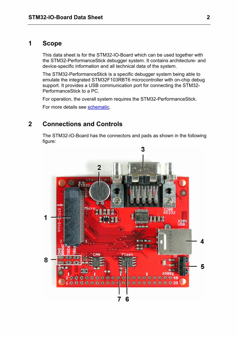
2 Connections and Controls The STM32-IO-Board has the connectors and pads as shown in the following figure:

STM32-IO-Board Data Sheet 3
1 Stick-IO-Connector (X500) 2 Microphone (MIC402) 3 RS232 Connector (X200) 4 USB connector (X201) 5 IrDA Transceiver (U203) 6 SPI Flash circuit (U300)
Note: only simplex mode with bi-directional data line is supported (pin PA6 is connected to pin PA7)
7 IO-Connector pads (X501) (also see table below) Note: the IO-Board printing is X500 which is wrong!
8 Pads for - external power connection +5V/GND (JP500) - external power enable (JP501) - external power enable via USB-B/VBUS (JP201)
The pads JP500 can be used to supply an external stabilized power +5V to the board and the stick when used in standalone operation without the PC host. This requires that the jumper JP501 is set to enable the internal +3.3V power supply.
Instead using the pads JP500 the external power can be supplied via the USB connector X201. For this the jumpers JP201 and JP501 has to be set.
The following table shows the allowed alternatives:
.
Mode Operation JP500 JP201 JP501
PC host powered via STM32-PerformanceStick
DashBoard HiTOP5
not connected
open open
external power via JP500
stand alone
power input
open closed
external power via X201
stand alone
not connected
closed closed

STM32-IO-Board Data Sheet 4
3 Interfaces Pin Assignment of the I/O-Connector X501
Pin Port Pin
Port
1 Reset *) 2 GND
3 Power_enable *) 4 GND
5 PC13 *) 6 GND
7 +5V 8 +5V
9 +3.3V 10 +3.3V
11 GND 12 GND
13 CAN_BM 14 PB6
15 CAN_BP 16 PB7
17 PC0 18 PC2
19 PC1 20 PC3
21 GNDA 22 GND
23 PC5 24 PB2
25 PC6 26 PB12
27 PC7 28 PB13
29 PC8 30 PB14
31 PC9 32 PB15
33 PC10 34 --
35 PC11 36 --
37 PC12 38 PA0
39 GND 40 GND
*) Reset, Power_enable and PC13 have a 47 kOhm pull-up to +3.3V and can be set by jumpers: 1-2 and 3-4 and 5-6
Note that CAN_BM and CAN_BP are the CAN bus signals without termination.

STM32-IO-Board Data Sheet 5
4 Connecting the Board to the STM32-PerformanceStick The STM32-IO-Board is connected to the STM32-PerformanceStick via an 80-pin PCB connector. See the following schematics and figure:
For the connection of the STM32-PerformanceStick to the PC you can use the USB extension cable included in the Starter Kit.
Caution
Connect the board and the stick only when not powered from the PC or external and in the orientation as shown in the figure above.
Please avoid any short-cuts by metallic parts touching the STM32-PerformanceStick or the STM32-IO-Board.
Do not supply external power to the STM32-IO-Board via the pads or the USB-B connector while the stick is connected to the PC. This may cause serious damage to your PC.
Modifications of the STM32-IO-Board or supplying of external power via the STM32-IO-Board is at your own risk.
Hitex or STMicroelectronics is not reliable for any damages caused by wrong handling.

STM32-IO-Board Data Sheet 6
5 Technical Data The features of the STM32-IO-Board are summarized as follows: • 2x40-pin 0.635mm pitch PCB extension Stick-I/O-connector for the STM32-
PerformanceStick MEC6-140-02-L-D-RA1 (Samtec)
• 2x20-pin IO connector pads with reset and IRQ capability via jumpers
• USB-B connector with USB protection circuit USBLC6-2 (STM)
• RS232 connector with driver circuit ST3222 (STM)
• IrDA device TFDU4101 (Vishay)
• SPI Flash device M25PE16 (STM)
• CAN Transceiver circuit L9616 (STM)
• Microphone EMY-62MP or similar (EKULIT) with TSH300 OP amplifier (STM)
• USB-powered via stick or from external USB-B or IO- connector with jumper selection
• Dimensions: appr. 60 x 65mm
The following applications can be shown in addition to the STM32-PerformanceStick-only applications: • External communication via USB, CAN, I2C and USART2
• External control of TIM1 and TIM4
• IrDA with USART1 or IR recorder/player for remote control
• SPI1 communication with SPI-Flash
• Measurement with ADC and GPIO inputs
• FFT analysis of microphone output
All functions mentioned above can be controlled by the PC DashBoard GUI.