stock trader system architecture description trader system architecture description michael stevens...
TRANSCRIPT
Stock Trader System
Architecture Description
Michael Stevens
[email protected] http://www.mestevens.com
Table of Contents 1. Purpose of Document 2 2. System Synopsis 2 3. Current Situation and Environment 3 3.1. Organizational Factors/Design Goals 3 3.2. Technological Factors (Operating environment and conditions) 3 3.2.1. Overview 3 3.2.2. Hardware 3 3.2.3. Architectural Styles 3 3.2.4. Design Patterns 3 3.2.5. Display Technology 4 3.2.6. Coding Conventions 4 3.2.7. Persistent Store 4 3.3. Product Factors (non-functional design goals) 4 4. Conceptual Architecture View (High Level Architecture) 4 5. Module Architecture View 5 6. Execution Architecture View 7 7. Code Architecture View 11
1. Purpose of Document The purpose of this document is to describe the architecture of the Stock Trader System (STS). This architecture document is part of a design plan for the development of the system. It provides abstractions that help manage the complexity of the software. The design plan is a structural plan that describes the elements of the system and the way they fit together. The other main aspect of this document is to provide abstractions that help manage the complexity of the system, and to provide a blueprint for system development. To satisfy these goals, this document is divided into six sections:
The first section is a system summary that describes the Stock Trader System’s (STS) basic functionality, the product’s features, the system interactions and the future of STS in terms of extensibility, maintainability and portability.
The second section is a global analysis of STS that describes the factors that influence the architecture of STS and the strategies for accommodating the factors in the architecture design.
The third section is the conceptual architecture view that maps STS functionality to components and connectors. It also addresses global properties such as performance and dependability.
The fourth section is the module architecture view that explicitly describes how STS functionality is mapped to the implementation, as well as how the underlying software platform is utilized.
The fifth section is the execution architecture view that describes the structure of the system in terms of its runtime platform elements such as threads, address spaces and how the system’s functionality is mapped to those platform elements. It also describes the possible locations, migrations and replications of runtime instances.
The sixth section is the code architecture view that describes how the software, both source and executable is organized. This view also describes these design decisions and how they relate to configuration management, multiple releases and testing.
2. System Synopsis The Stock Trading System is a system that can be accessed by anyone on the Internet who is interested in trading stocks online. The STS will permit the trader to log into and access account information and conduct simulated stock transactions over the Internet. A marketing analysis has determined that no more than 10,000 simultaneous users will be logged into the system at one time. Other non-functional requirements dictate a five second response time for all transactions.
Once the STS web site has been accessed, the trader will log into the system by typing in an id and password. Off the shelf (OTS) software in a future enhancement of the system will handle data encryption for transmission on the network. The system will allow the trader to buy and sell stocks, obtain stock quotes from a real time stock market
and access personal transaction history. The system will display the trader’s account information that includes a real-time summary of the cash balance, net-worth and stock portfolio for the trader.
The system will interact with a real-time stock market using stock issue information that changes on a second by second basis.
The STS is very interested in attracting new customers, so all accounts will have an initial cash balance of $100,000. The trader will have the ability to add money to their cash account in $1,000 increments.
3. Current Situation and Environment
3.1. Organizational Factors/Design Goals Several organization factors are driving the architectural decisions made in this document. It is the desire to of the team to develop all functionality in-house rather than to use off-the-shelf components. The schedule to deliver the product is aggressive. The architecture should facilitate the development in such a way as to minimize effort to achieve the schedule. The development team’s Java coding skills are low, so the architecture should provide abstractions to hide complexities. The development team is physically distributed, so it is necessary for the architecture to provide an extremely loose coupling between the system components assigned to the disparate teams
3.2. Technological Factors (Operating environment and conditions)
3.2.1. Overview The system is a remote stock trading system. The functional requirements include the ability to trade stocks on a network using a browser. Multiple users must be supported. A non-functional requirement specifies that the system must support 10,000 concurrent users. The system will be developed in Java that will provide a highly portable system. It will have the ability to run on a number of different operating systems.
3.2.2. Hardware The physical hardware may range from a single CPU running a Windows operating system to a multiple CPU Unix derivative system to an OS390 Mainframe system with little or no code changes. Since all source code is written in Java and standard Java Virtual Machines exist for many systems, the system will scale from a small number of users to a very high number of users extremely easily.
3.2.3. Architectural Styles The architecture includes the implementation of several design patterns and architectural styles. The Model-View-Controller architectural style is employed to provide distinct separation between processing, display and object model concerns. The MVC architecture is used to divide responsibility among objects involved in maintaining and presenting data so as to minimize the degree of coupling between objects. In MVC architecture, the model represents application data and the business rules that govern access and modification to the data. The model notifies the views when it changes and provides the ability for the view to query the model about its state. A view renders the model to the user. It accesses the internal attributes of the model objects and specifies how that data should be represented. The controller defines application behavior. It interprets user actions and performs actions on the model to change the models state. The MVC architectural style is implemented using several design patterns.
Another architectural style employed is the partitioned style. Each group of related functionality is placed in a separate package. Each package is loosely defined in this document as a component. The component has a set of interfaces. Each component is at a peer level with other components and is responsible for a different category of service.
3.2.4. Design Patterns The first is the Observer pattern. The various views register as observers with the model notifiers when the user logs in. The views register only with those model components which they have interest in. When a change occurs somewhere in the model component, the model notifier for that component notifies each of the views that have
registered that a change has occurred. The views have the responsibility to update their state from the model components.
The second is the command pattern. When an event occurs in the system, the request is sent to the controller for processing. The controller passes the request to a request receiver. The request receiver translates the request into an appropriate command and passes it back to the controller. The controller then executes the command that may update various model objects that may fire updates to the various views which have registered with the models.
The third pattern implemented is the singleton patterns. Many objects in the system serve as type-based components in which there must be only one instance in the system for all users. For example, the Market component exists only once and has methods for purchasing a stock. The stock purchase method accepts all state information such as the user, and the trade info and executes the trade in the model objects.
The fourth pattern implemented is the Facade pattern. Each package defines a component. Each component defines an interface factory which provides a façade into the component. When an object outside the component needs a service, it goes to the component façade to obtain an interface. The pattern serves several purposes. First, it hides the complexity of the component’s objects from the user. All the user must understand is the façade interfaces to the component. It also provides a means of decoupling the component interfaces from their implementation. This will allow the component implementation to change without affecting the component clients.
The fifth pattern implemented is the Factory method for returning the appropriate objects that implement the component interfaces.
3.2.5. Display Technology The system uses Java Server Pages as a presentation technology. Java beans and standard java objects are used to represent the controller, model and view concerns.
3.2.6. Coding Conventions Standard coding conventions outlined in the document by Scott Ambler will be used. http://www.msnusers.com/TeamGreenStckTradeSystem/files/Standards%2FjavaCodingStandards%2Epdf
3.2.7. Persistent Store No database will be used, all state will exist only for the execution of the system. Object initialization will be done either by reading from a file, or by static data loads in the object constructor.
3.3. Product Factors (non-functional design goals) The product consists of a remote browser communication with an application server to provide display, session state and application behavior. The user interface is a standard HTML interface generated from a set of Java Server Pages processed by the application server. The performance of the system must be less than three second response time on every page request. The system, when deployed should be have a 99.9% availability during market hours, and a 99% availability during non-market hours.
4. Conceptual Architecture View (High Level Architecture) The system consists of several functional and non-functional components that communicate through loosely coupled interfaces. The JSP code communicates only with the application controller, view factory and various views. The presentation code is restricted from using model objects directly. The application controller creates and executes commands that in turn modify component states. The state changes in the components trigger notifications to registered views in order to perform view state synchronization.
The worst-case response time from URL request receipt to server response is five seconds. The servers will be scaled to satisfy this requirement. Several server products exist which allow the creation of server farms to distribute the session context objects across servers for higher performance and greater reliability. The model components are designed in such a way as to facilitate their conversion to enterprise java bean distributed components that may be deployed in an EJB container and managed by sophisticated server software to provide a high performance, dependable n-tier system.
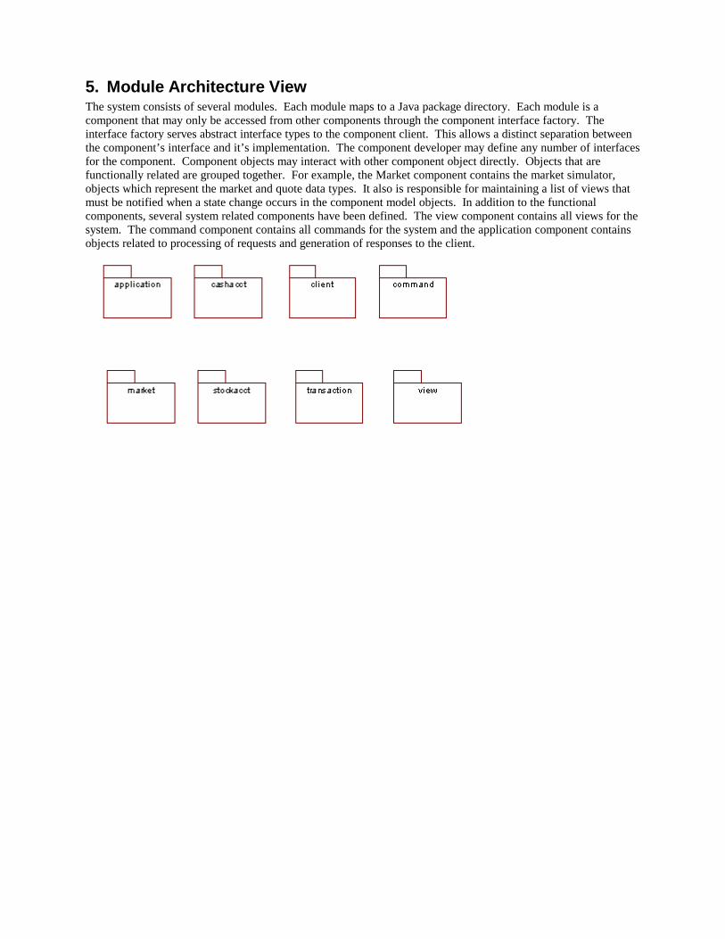
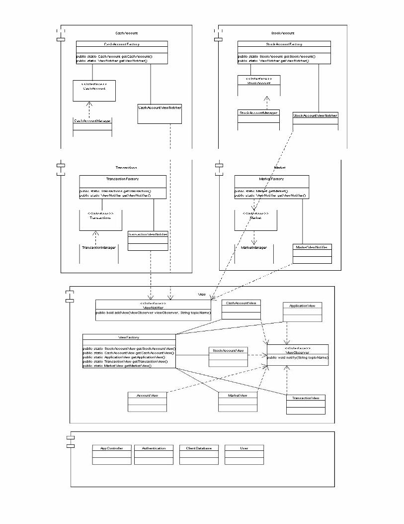
5. Module Architecture View The system consists of several modules. Each module maps to a Java package directory. Each module is a component that may only be accessed from other components through the component interface factory. The interface factory serves abstract interface types to the component client. This allows a distinct separation between the component’s interface and it’s implementation. The component developer may define any number of interfaces for the component. Component objects may interact with other component object directly. Objects that are functionally related are grouped together. For example, the Market component contains the market simulator, objects which represent the market and quote data types. It also is responsible for maintaining a list of views that must be notified when a state change occurs in the component model objects. In addition to the functional components, several system related components have been defined. The view component contains all views for the system. The command component contains all commands for the system and the application component contains objects related to processing of requests and generation of responses to the client.
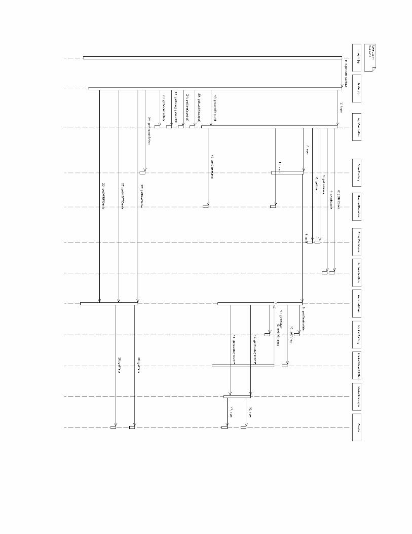
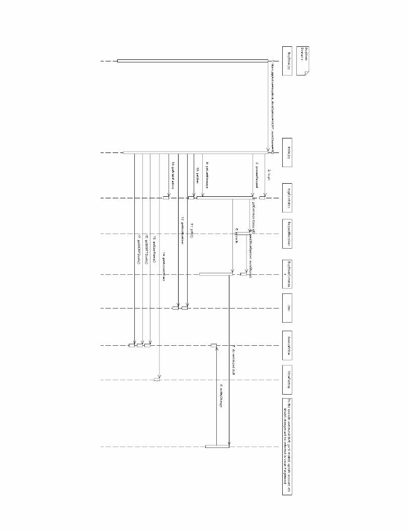
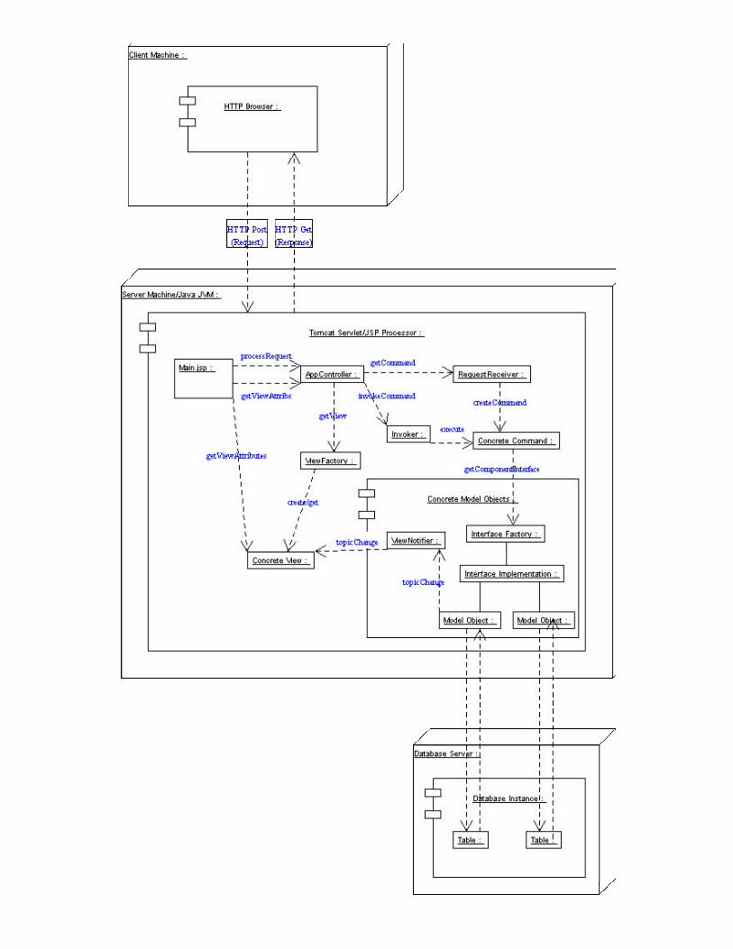
6. Execution Architecture View The system will be typically deployed in a three-tier configuration. The client machine will run a standard HTML browser. The browser produces HTTP Posts for form submits and HTTP Get requests. For persistent data store, a database server may be used in the third tier for object persistence. In our test system, the persistent data store will not be used, or a file based persistent store will be used. When the browser makes a URL request, the server receives the request and sends the request to the generates server. The server generates the response using various .JSP pages that access views in the system for dynamic portions of the HTML response. When the HTML and dynamic portions are generated, the HTML is sent to the browser for display. When the browser performs a URL request, the request is sent to the request receiver to generate a command if the action tag matches a system command. If a command exists for the action tag, the command is created and invoked by the invoker. Model objects are modified by the command and those modifications in the model objects trigger a notification to the views that have registered interest in the topic served by the model objects. When the command is complete, the HTML response is generated by using the static HTML in the JSP page along with dynamic elements which are requested by the JSP pages and served by the changed view objects.
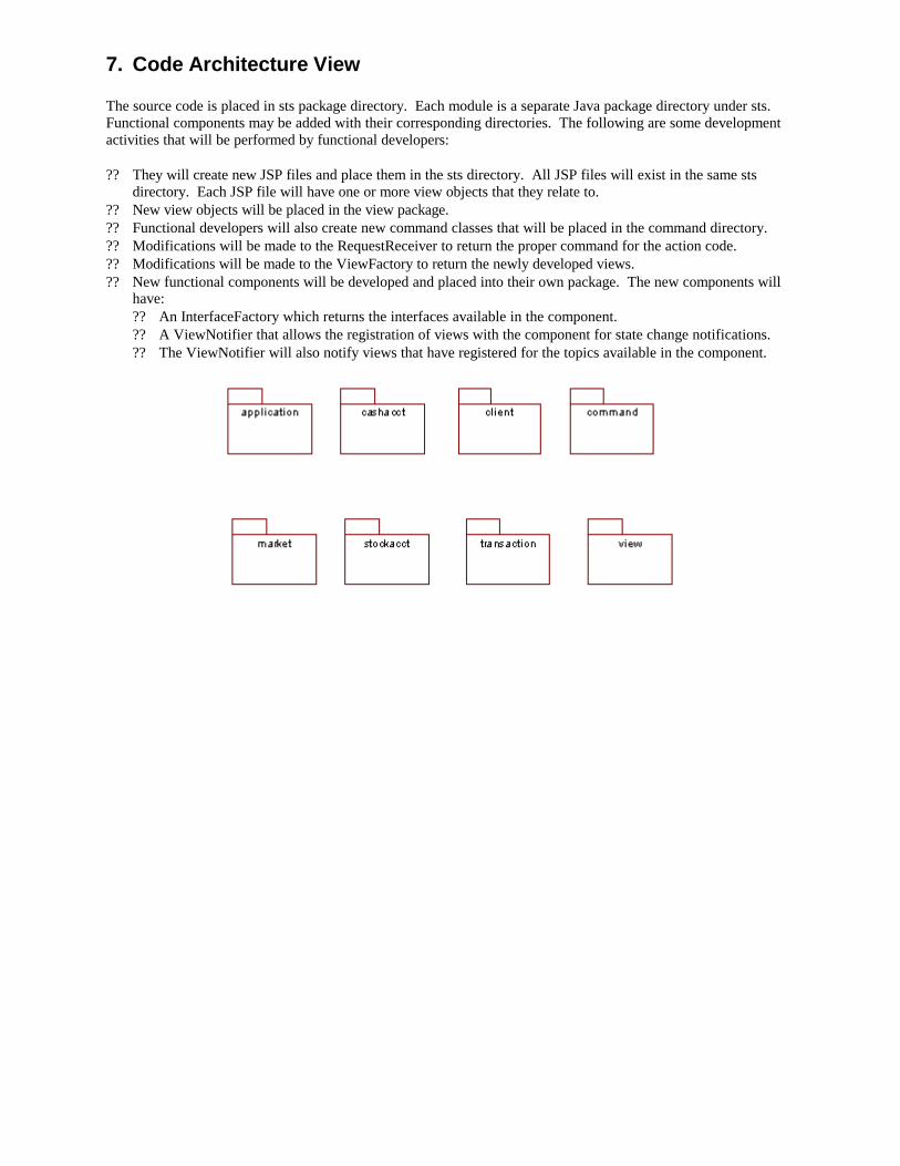
7. Code Architecture View The source code is placed in sts package directory. Each module is a separate Java package directory under sts. Functional components may be added with their corresponding directories. The following are some development activities that will be performed by functional developers: ? ? They will create new JSP files and place them in the sts directory. All JSP files will exist in the same sts
directory. Each JSP file will have one or more view objects that they relate to. ? ? New view objects will be placed in the view package. ? ? Functional developers will also create new command classes that will be placed in the command directory. ? ? Modifications will be made to the RequestReceiver to return the proper command for the action code. ? ? Modifications will be made to the ViewFactory to return the newly developed views. ? ? New functional components will be developed and placed into their own package. The new components will
have: ? ? An InterfaceFactory which returns the interfaces available in the component. ? ? A ViewNotifier that allows the registration of views with the component for state change notifications. ? ? The ViewNotifier will also notify views that have registered for the topics available in the component.
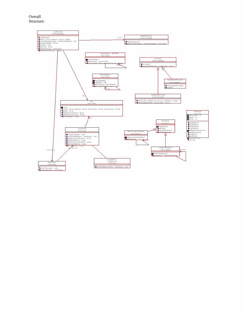
Overall Structure:
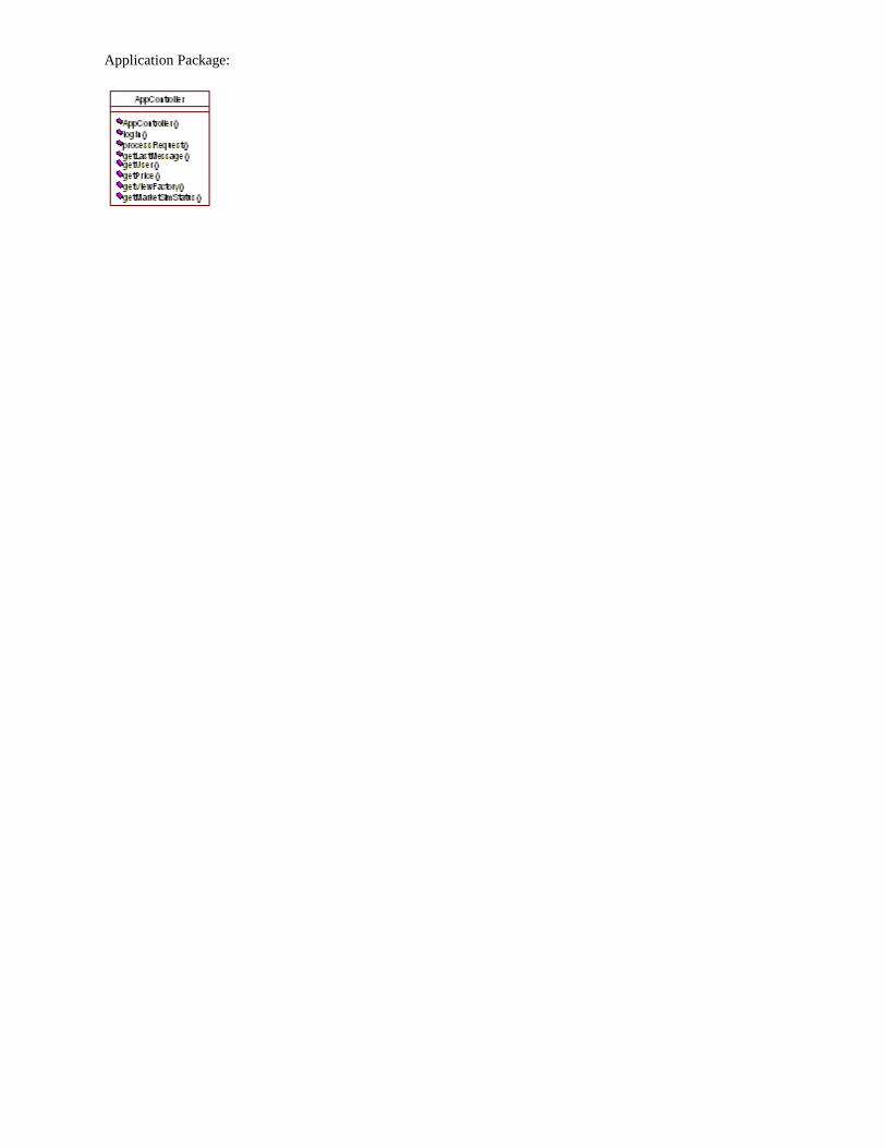
Application Package:
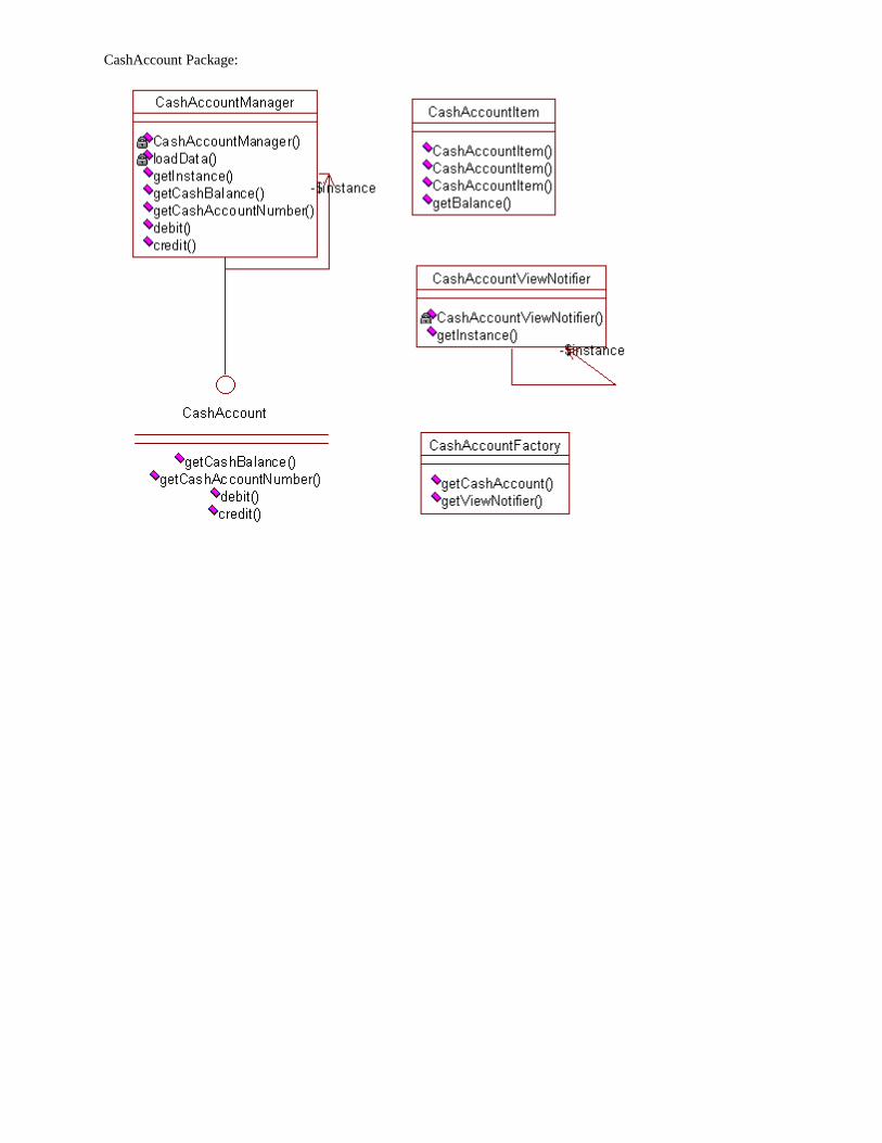
CashAccount Package:
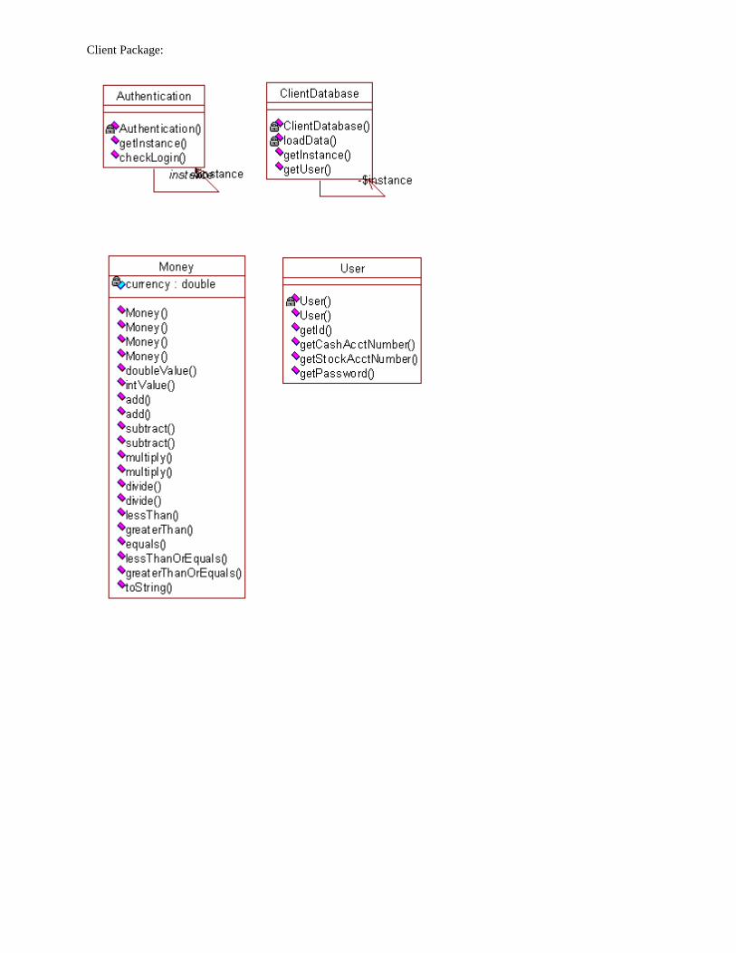
Client Package:
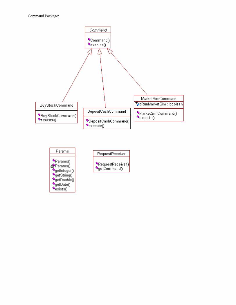
Command Package:
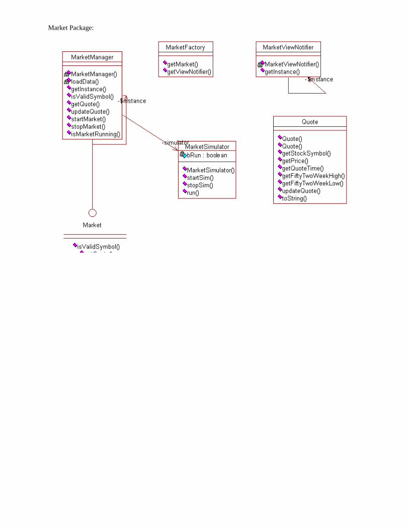
Market Package:
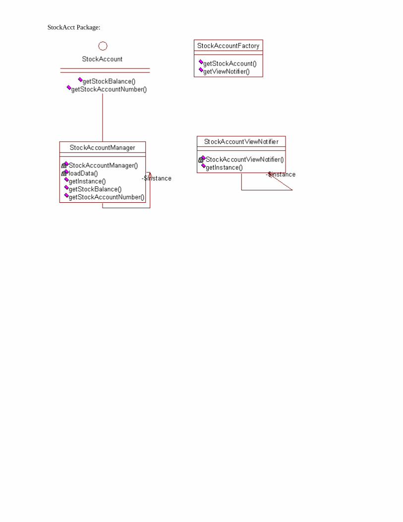
StockAcct Package:
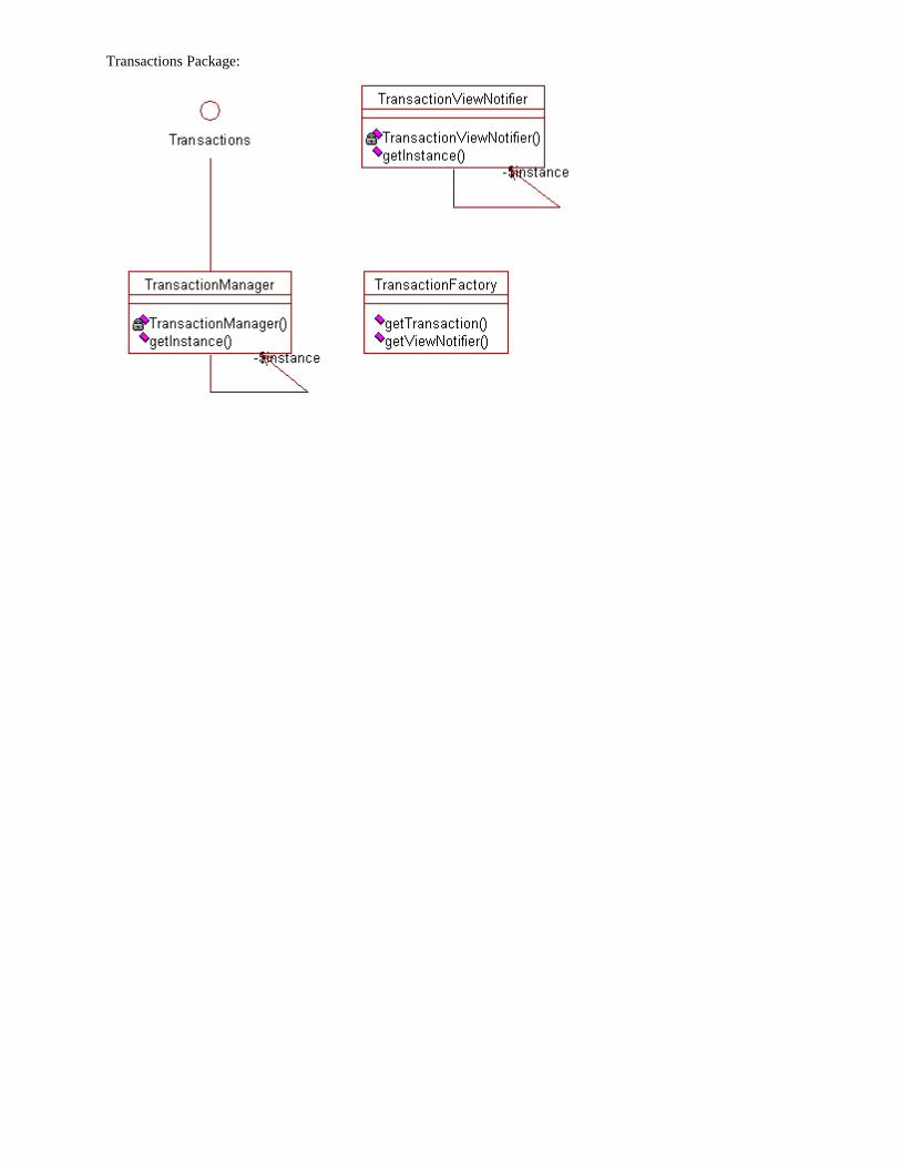
Transactions Package:
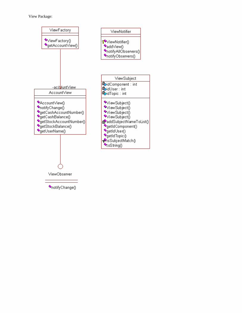
View Package: