stol ch 801 rear fuselage assembly - zenith aircraft company · 2014-10-04 · stol ch 801 zenith...
TRANSCRIPT

STOL CH 801
Zenith Aircraft Company www.zenithair.com
REAR FUSELAGE ASSEMBLYSECTION 1 - Page 1 of 14
Edition 3.0 (04/02) © 2002 Zenith Aircraft Co
STOL CH 801 REAR FUSELAGE ASSEMBLY
SECTION 1
Rear Fuselage Side Assembly Ref Dwg 8FR-1
RECOMMEND: Back drill through the pilot holes in the skin with #40 drill bit and assemble with 3/32” clecos. When all the parts are installed, back drill with the drill bit for the rivet size. Some rivet lines are back drilled through more than once.

STOL CH 801
Zenith Aircraft Company www.zenithair.com
REAR FUSELAGE ASSEMBLYSECTION 1 - Page 2 of 14
Edition 3.0 (04/02) © 2002 Zenith Aircraft Co
Start by trimming the top and bottom edge of the Side skins. The photo indicates to cut to the inside of the line, but it’s a good idea to leave about 1/2mm of the black line as a witness. Trim carefully as this will affect the final size of the aircraft and how some other parts fit.
FUSELAGE FORWARD SIDE SKIN 8F2-2A Note: The edges of the skin 8F2-2A are not a straight line. Check: Edge distance = 9.5mm (center of the pre-drilled pilot holes to the edge cut line) LEFT & RIGHT SKINS ARE IDENTICAL
File the edge smooth to remove any slivers or sharp points. The body file is used to plane the edge for a smooth continuous curve.
Body File Sykes-Pickavant blades Fine cut, flat double side flexible 14”-13 TPI U.S. Industrial Tool & Supply P/N TA578F http://www.ustool.com
STOL CH 801
Zenith Aircraft Company www.zenithair.com
REAR FUSELAGE ASSEMBLYSECTION 1 - Page 3 of 14
Edition 3.0 (04/02) © 2002 Zenith Aircraft Co
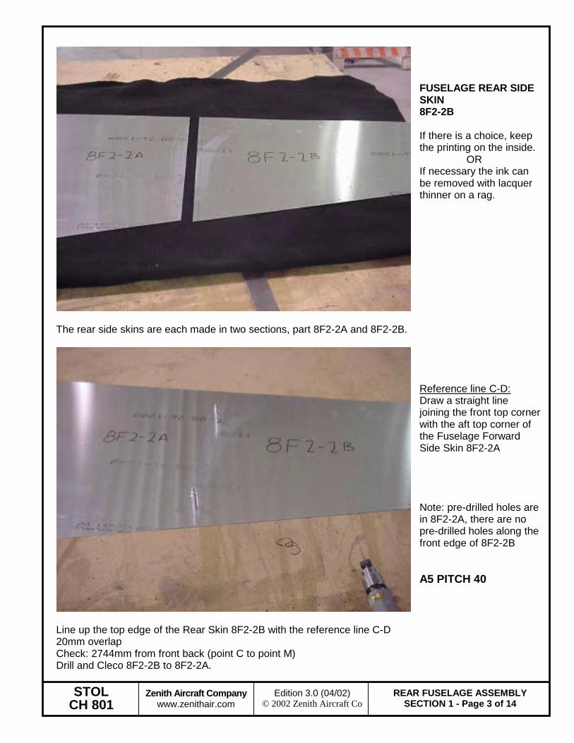
The rear side skins are each made in two sections, part 8F2-2A and 8F2-2B.
FUSELAGE REAR SIDE SKIN 8F2-2B If there is a choice, keep the printing on the inside. OR If necessary the ink can be removed with lacquer thinner on a rag.
Line up the top edge of the Rear Skin 8F2-2B with the reference line C-D 20mm overlap Check: 2744mm from front back (point C to point M) Drill and Cleco 8F2-2B to 8F2-2A.
Reference line C-D: Draw a straight line joining the front top corner with the aft top corner of the Fuselage Forward Side Skin 8F2-2A Note: pre-drilled holes are in 8F2-2A, there are no pre-drilled holes along the front edge of 8F2-2B A5 PITCH 40
STOL CH 801
Zenith Aircraft Company www.zenithair.com
REAR FUSELAGE ASSEMBLYSECTION 1 - Page 4 of 14
Edition 3.0 (04/02) © 2002 Zenith Aircraft Co
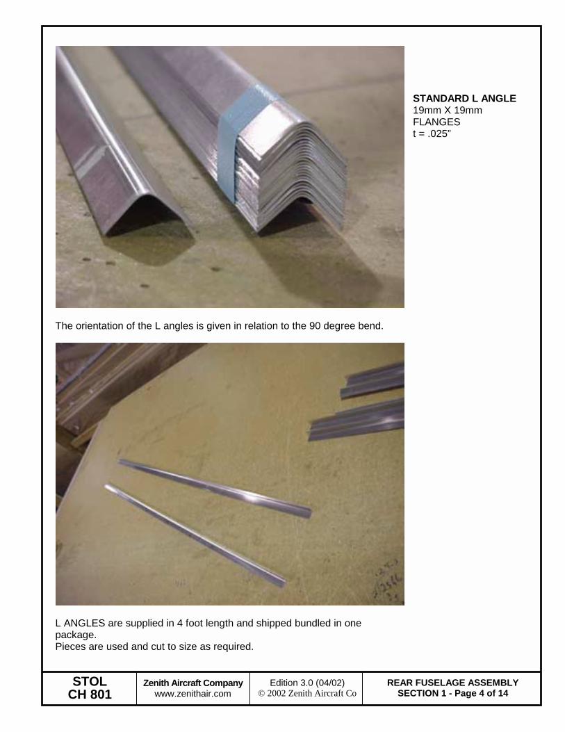
The orientation of the L angles is given in relation to the 90 degree bend.
STANDARD L ANGLE 19mm X 19mm FLANGES t = .025”
L ANGLES are supplied in 4 foot length and shipped bundled in one package. Pieces are used and cut to size as required.
STOL CH 801
Zenith Aircraft Company www.zenithair.com
REAR FUSELAGE ASSEMBLYSECTION 1 - Page 5 of 14
Edition 3.0 (04/02) © 2002 Zenith Aircraft Co
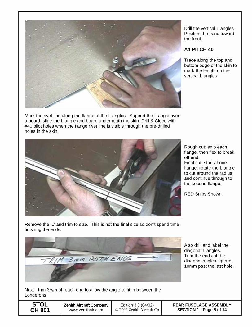
Mark the rivet line along the flange of the L angles. Support the L angle over a board; slide the L angle and board underneath the skin. Drill & Cleco with #40 pilot holes when the flange rivet line is visible through the pre-drilled holes in the skin.
Drill the vertical L angles Position the bend toward the front. A4 PITCH 40 Trace along the top and bottom edge of the skin to mark the length on the vertical L angles
Remove the ‘L’ and trim to size. This is not the final size so don’t spend time finishing the ends.
Rough cut: snip each flange, then flex to break off end. Final cut: start at one flange, rotate the L angle to cut around the radius and continue through to the second flange. RED Snips Shown.
Next - trim 3mm off each end to allow the angle to fit in between the Longerons
Also drill and label the diagonal L angles. Trim the ends of the diagonal angles square 10mm past the last hole.
STOL CH 801
Zenith Aircraft Company www.zenithair.com
REAR FUSELAGE ASSEMBLYSECTION 1 - Page 6 of 14
Edition 3.0 (04/02) © 2002 Zenith Aircraft Co
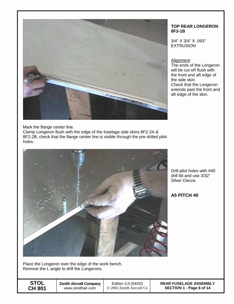
Mark the flange center line. Clamp Longeron flush with the edge of the fuselage side skins 8F2-2A & 8F2-2B; check that the flange center line is visible through the pre-drilled pilot holes.
TOP REAR LONGERON 8F3-1B 3/4” X 3/4” X .093” EXTRUSION Alignment: The ends of the Longeron will be cut-off flush with the front and aft edge of the side skin. Check that the Longeron extends past the front and aft edge of the skin.
Place the Longeron over the edge of the work bench. Remove the L angle to drill the Longerons.
Drill pilot holes with #40 drill bit and use 3/32” Silver Clecos A5 PITCH 40

STOL CH 801
Zenith Aircraft Company www.zenithair.com
REAR FUSELAGE ASSEMBLYSECTION 1 - Page 7 of 14
Edition 3.0 (04/02) © 2002 Zenith Aircraft Co
The Longerons are a single piece of extrusion the full length of the rear fuselage side skins 8F2-2A & 8F2-2B
The Longerons, are installed flush with the edge of the skins in the corner between the sides and the top skin.
Trim the overhang: The top flange is square to the side, the side flange is cut on an angle by tracing the edge of the skin (front & rear).
STOL CH 801
Zenith Aircraft Company www.zenithair.com
REAR FUSELAGE ASSEMBLYSECTION 1 - Page 8 of 14
Edition 3.0 (04/02) © 2002 Zenith Aircraft Co
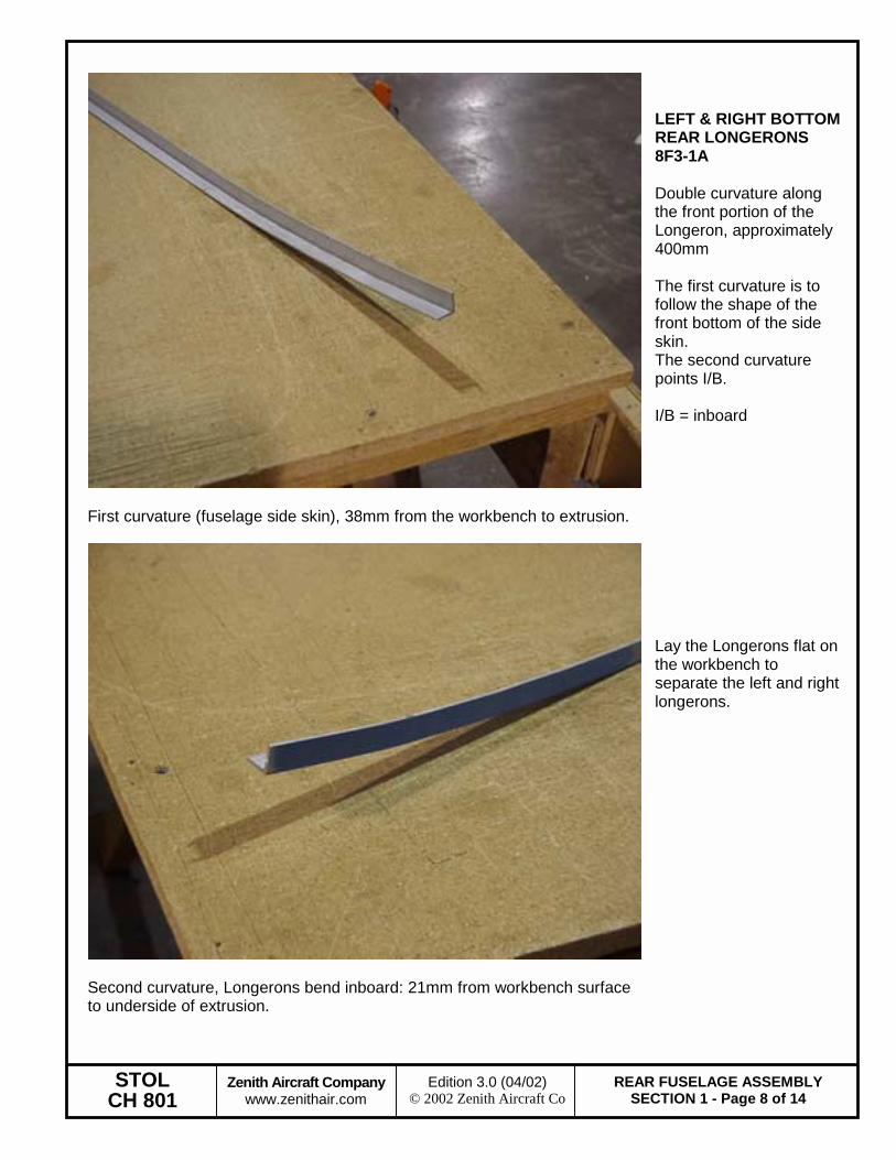
First curvature (fuselage side skin), 38mm from the workbench to extrusion.
LEFT & RIGHT BOTTOM REAR LONGERONS 8F3-1A Double curvature along the front portion of the Longeron, approximately 400mm The first curvature is to follow the shape of the front bottom of the side skin. The second curvature points I/B. I/B = inboard
Second curvature, Longerons bend inboard: 21mm from workbench surface to underside of extrusion.
Lay the Longerons flat on the workbench to separate the left and right longerons.
STOL CH 801
Zenith Aircraft Company www.zenithair.com
REAR FUSELAGE ASSEMBLYSECTION 1 - Page 9 of 14
Edition 3.0 (04/02) © 2002 Zenith Aircraft Co
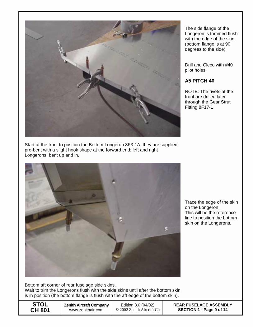
Start at the front to position the Bottom Longeron 8F3-1A, they are supplied pre-bent with a slight hook shape at the forward end: left and right Longerons, bent up and in.
The side flange of the Longeron is trimmed flush with the edge of the skin (bottom flange is at 90 degrees to the side). Drill and Cleco with #40 pilot holes. A5 PITCH 40 NOTE: The rivets at the front are drilled later through the Gear Strut Fitting 8F17-1
Bottom aft corner of rear fuselage side skins. Wait to trim the Longerons flush with the side skins until after the bottom skin is in position (the bottom flange is flush with the aft edge of the bottom skin).
Trace the edge of the skin on the Longeron This will be the reference line to position the bottom skin on the Longerons.
STOL CH 801
Zenith Aircraft Company www.zenithair.com
REAR FUSELAGE ASSEMBLYSECTION 1 - Page 10 of 14
Edition 3.0 (04/02) © 2002 Zenith Aircraft Co
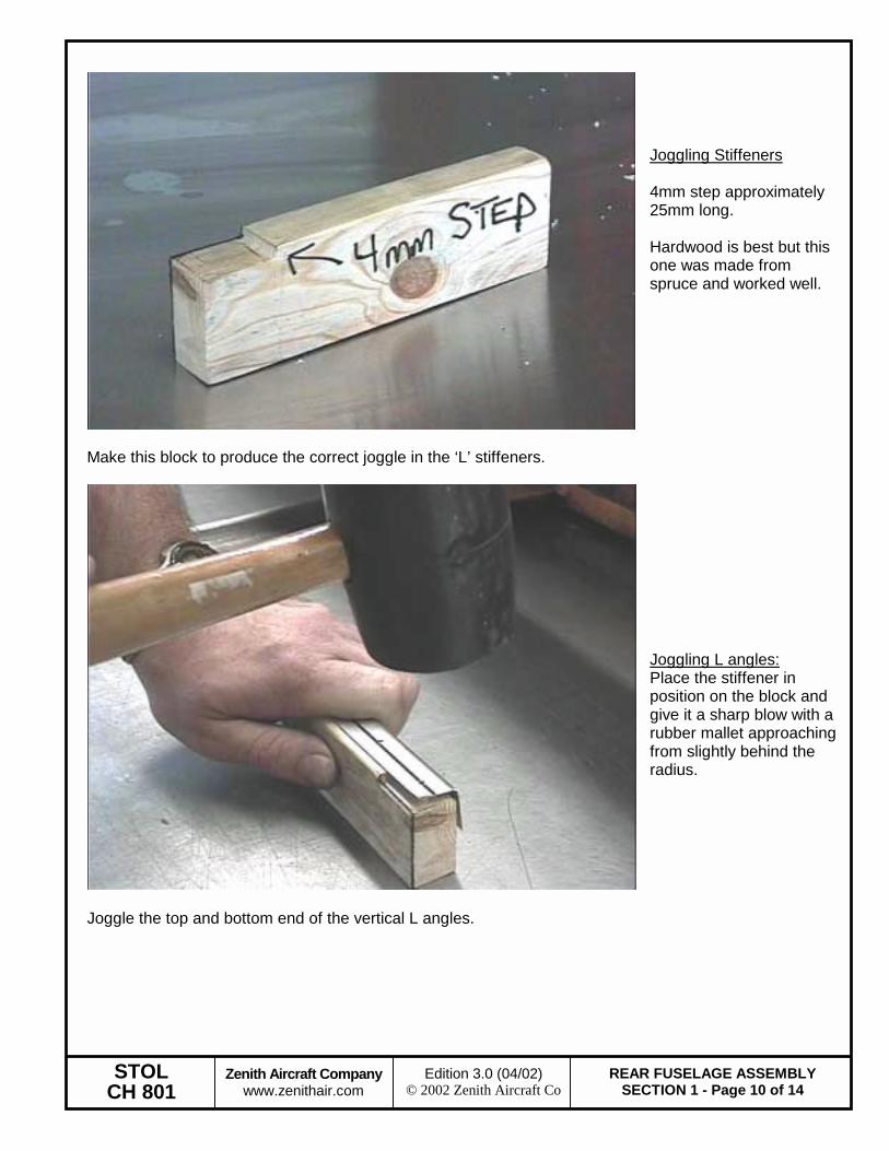
Make this block to produce the correct joggle in the ‘L’ stiffeners.
Joggling Stiffeners 4mm step approximately 25mm long. Hardwood is best but this one was made from spruce and worked well.
Joggle the top and bottom end of the vertical L angles.
Joggling L angles: Place the stiffener in position on the block and give it a sharp blow with a rubber mallet approaching from slightly behind the radius.
STOL CH 801
Zenith Aircraft Company www.zenithair.com
REAR FUSELAGE ASSEMBLYSECTION 1 - Page 11 of 14
Edition 3.0 (04/02) © 2002 Zenith Aircraft Co
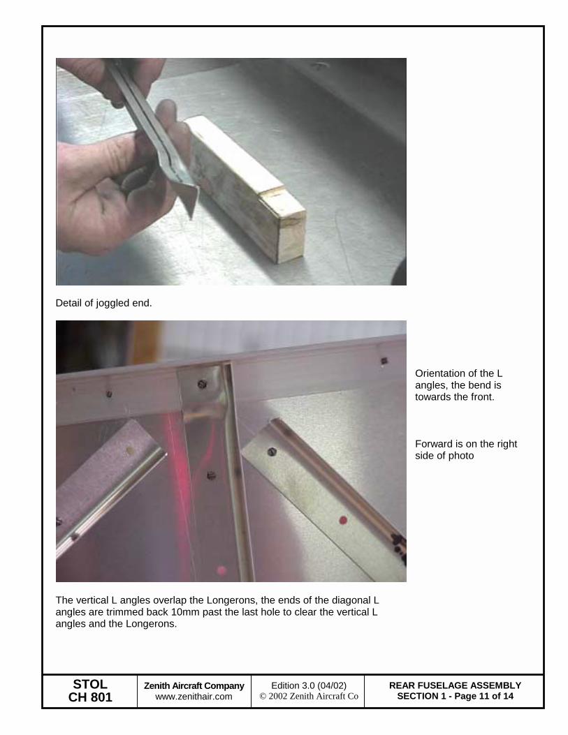
Detail of joggled end.
The vertical L angles overlap the Longerons, the ends of the diagonal L angles are trimmed back 10mm past the last hole to clear the vertical L angles and the Longerons.
Orientation of the L angles, the bend is towards the front. Forward is on the right side of photo
STOL CH 801
Zenith Aircraft Company www.zenithair.com
REAR FUSELAGE ASSEMBLYSECTION 1 - Page 12 of 14
Edition 3.0 (04/02) © 2002 Zenith Aircraft Co
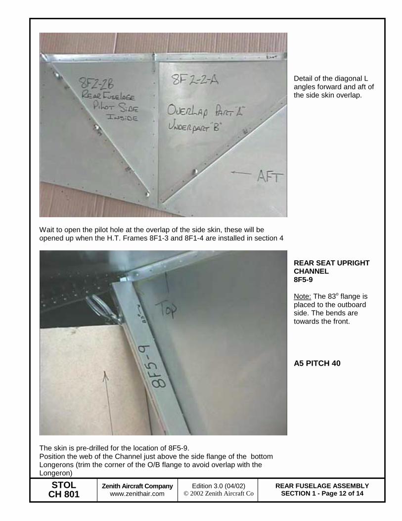
Wait to open the pilot hole at the overlap of the side skin, these will be opened up when the H.T. Frames 8F1-3 and 8F1-4 are installed in section 4
Detail of the diagonal L angles forward and aft of the side skin overlap.
The skin is pre-drilled for the location of 8F5-9. Position the web of the Channel just above the side flange of the bottom Longerons (trim the corner of the O/B flange to avoid overlap with the Longeron)
REAR SEAT UPRIGHT CHANNEL 8F5-9 Note: The 83o flange is placed to the outboard side. The bends are towards the front. A5 PITCH 40
STOL CH 801
Zenith Aircraft Company www.zenithair.com
REAR FUSELAGE ASSEMBLYSECTION 1 - Page 13 of 14
Edition 3.0 (04/02) © 2002 Zenith Aircraft Co
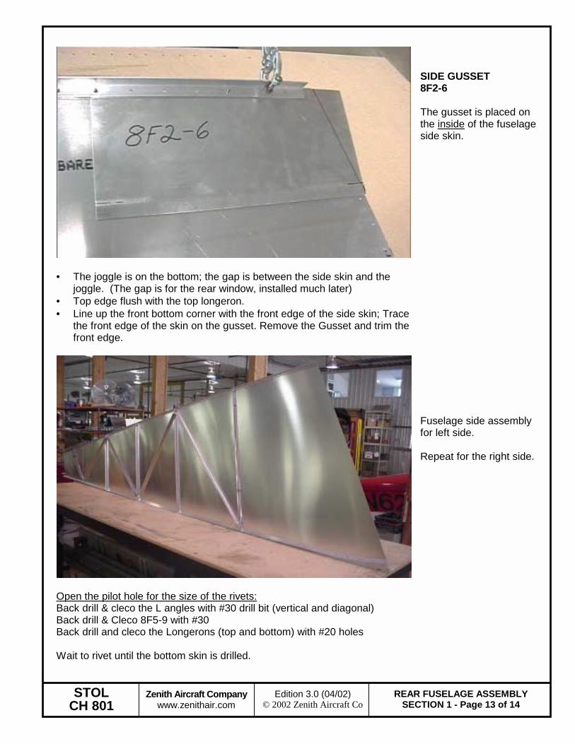
• The joggle is on the bottom; the gap is between the side skin and the
joggle. (The gap is for the rear window, installed much later) • Top edge flush with the top longeron. • Line up the front bottom corner with the front edge of the side skin; Trace
the front edge of the skin on the gusset. Remove the Gusset and trim the front edge.
SIDE GUSSET 8F2-6 The gusset is placed on the inside of the fuselage side skin.
Open the pilot hole for the size of the rivets: Back drill & cleco the L angles with #30 drill bit (vertical and diagonal) Back drill & Cleco 8F5-9 with #30 Back drill and cleco the Longerons (top and bottom) with #20 holes Wait to rivet until the bottom skin is drilled.
Fuselage side assembly for left side. Repeat for the right side.
STOL CH 801
Zenith Aircraft Company www.zenithair.com
REAR FUSELAGE ASSEMBLYSECTION 1 - Page 14 of 14
Edition 3.0 (04/02) © 2002 Zenith Aircraft Co
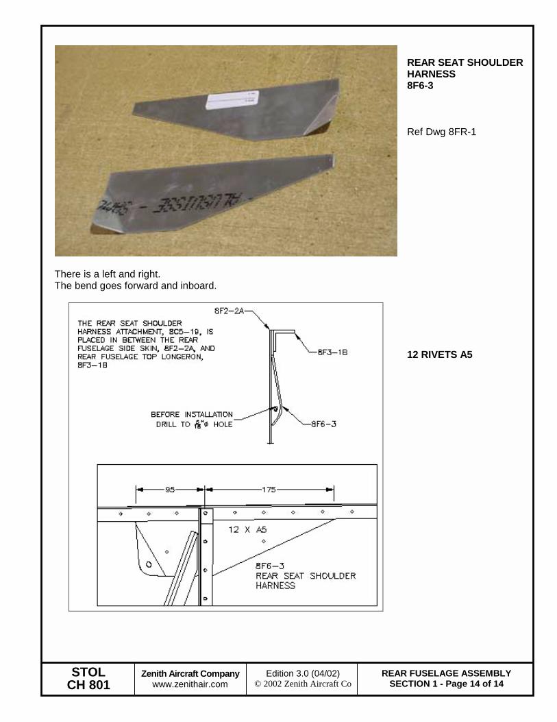
There is a left and right. The bend goes forward and inboard.
REAR SEAT SHOULDER HARNESS 8F6-3 Ref Dwg 8FR-1
12 RIVETS A5