storage tanks and other field facilitiesdocshare04.docshare.tips/files/5247/52478323.pdf · the use...
TRANSCRIPT

8Storage Tanks and OtherField Facilities
This chapter is devoted to the discussion of storage tanks of crude oil andother hydrocarbons, vapor recovery units (VRUs), and piping in the oilfield, including gathering schemes.
8.1 STORAGE TANKS
8.1.1 Introduction
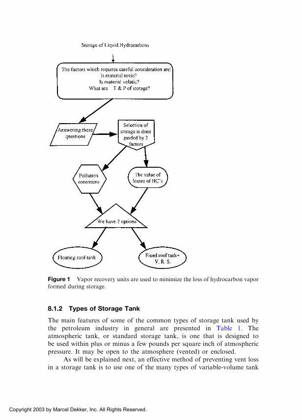
The design of storage tanks for crude oil and petroleum products requires,in general, careful consideration of the following important factors:
� The vapor pressure of the materials to be stored� The storage temperature and pressure� Toxicity of the petroleum material
In order to meet the environmental constraints on air pollution, to preventfire hazards, and to avoid losses of valuable petroleum products at thesame time, it is recommended to adopt the following:
� The use of floating-roof tanks for petroleum materials with avapor pressure of 1.12–11.5 psia (at the storage temperature) or
� Using fixed-roof tanks along with the VRU system (to bedescribed later).
These alternatives are schematically illustrated in Figure 1.Storage tanks for crude oil are needed in order to receive and collect
oil produced by wells, before pumping to the pipelines as well as to allowfor measuring oil properties, sampling, and gauging.
Copyright 2003 by Marcel Dekker, Inc. All Rights Reserved.
8.1.2 Types of Storage Tank
The main features of some of the common types of storage tank used bythe petroleum industry in general are presented in Table 1. Theatmospheric tank, or standard storage tank, is one that is designed tobe used within plus or minus a few pounds per square inch of atmosphericpressure. It may be open to the atmosphere (vented) or enclosed.
As will be explained next, an effective method of preventing vent lossin a storage tank is to use one of the many types of variable-volume tank
Figure 1 Vapor recovery units are used to minimize the loss of hydrocarbon vapor
formed during storage.
Copyright 2003 by Marcel Dekker, Inc. All Rights Reserved.

Table 1 Summary of Refinery Storage Tanks
Characteristics
Standard Storage
Tanks
Conservation-Type Storage Tanks
I (Floating Roofs) II (Variable-Vapor-Space) III (Pressure Storage)
Evaporation
losses
High Significantly reduced Significantly reduced Prevented or eliminated
Operating
conditions
Recommended for
liquids whose vapor
pressure is atmospheric
or below at storage
conditions (vented).
Allow no vapor space
above the liquid;
level (no venting)
Allow the air-vapor mixture
to change volume at
constant or variable
pressure (no venting)
Allow the pressure in the
vapor space to build up.
Tanks are capable of
withstanding the maximum
pressure without venting.
Sub-classification 1. Rectangular
2. Cylinderical:
a) Horizontal
b) Vertical
1. Lifter roof, which
is a gas holder mounted
on a standard storage tank.
2. Vapor-dome
1. Low-pressure storage
normally designed for
2.5–5 psig (up to 15 psig)
2. High pressure storage:
30–200 psig
Typical types Cone-roof-vertical
(cylinderical tanks)
Floating-roof,
wiggins-Hidek type
Lifter roof tanks,
wiggins dry seal type
Spheroids and hemispheroids
for low pressure storage,
spheres for high
pressure storage
Applications Heavy refinery
products
Sour crude oils,
light crude oils,
light products.
Light refinery product
and distillates
Spheriods are used to store
aviation, motor, jet fuels.
Spheres are used to store
natural gasoline and LPG.
Copyright 2003 by Marcel Dekker, Inc. All Rights Reserved.
(type II in Table 1). These are built under API Standard 650. They mayhave floating roofs of the double-deck or single-deck type. These are lifter-roof types in which the roof either has a skirt moving up and down in anannular seal or is connected to the tank shell by a flexible membrane.
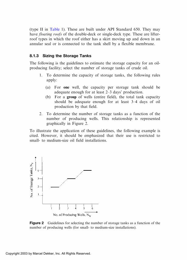
8.1.3 Sizing the Storage Tanks
The following is the guidelines to estimate the storage capacity for an oil-producing facility; select the number of storage tanks of crude oil.
1. To determine the capacity of storage tanks, the following rulesapply:
(a) For one well, the capacity per storage tank should beadequate enough for at least 2–3 days’ production.
(b) For a group of wells (entire field), the total tank capacityshould be adequate enough for at least 3–4 days of oilproduction by that field.
2. To determine the number of storage tanks as a function of thenumber of producing wells. This relationship is representedgraphically in Figure 2.
To illustrate the application of these guidelines, the following example iscited. However, it should be emphasized that their use is restricted tosmall- to medium-size oil field installations.
Figure 2 Guidelines for selecting the number of storage tanks as a function of the
number of producing wells (for small- to medium-size installations).
Copyright 2003 by Marcel Dekker, Inc. All Rights Reserved.

Example 1
For a lease consisting of five producing wells, each with an averageproduction capacity of 10,000 bbl/day, find the approximate total storagecapacity and the number of storage tanks.
Solution
Using rule a,
Capacity or the size of one tank ¼ 2�3 days of oil production/well
¼ ð2:5Þð10,000Þ¼ 25,000 bbl=well
Now, for five wells,
Total storage capacity ¼ ð5Þð25,000Þ¼ 125,000 bbl
Using correlation,
Storage capacity for the entire lease ¼ 3�4 days of oil
production by lease
¼ ð3:5Þð50,000Þ¼ 175,000 bbl
Conclusions:
The number of storage tanks according to rule a is 125,000/25,000¼ 5 tanks
The number of storage tanks according to rule b, assuming storagecapacity per tank the same as computed in rule a is 175,000/25,000¼ 7 tanks
Finally, the number of storage tanks as computed graphically, using Figure2 is 4. Now, comparing the results obtained, the appropriate number ofstorage tanks required by the lease is five to six.
8.2 VAPOR RECOVERY UNITS
8.2.1 Background
The loss of hydrocarbon vapors formed above crude oil or its products—when stored—could be minimized using what is called vapor recoveryunits (VRUs). If allowed to escape to the atmosphere, these vapors will
Copyright 2003 by Marcel Dekker, Inc. All Rights Reserved.

not only cause a loss of income due to loss of hydrocarbon volume and
change in the API of the oil but will also lead to pollution and fire
hazards.The three main functions for the vapor recovery system are (as
illustrated in Fig. 3) as follows:
1. To collect vapor from storage/loading facilities
2. To reliquefy vapors
3. To return liquid hydrocarbons to storage
Basically, when we talk about a VRU, what we are looking for is tohook our storage tanks to a ‘‘breather’’ system such as the following:
� During the day, when the temperature rises and vaporization ofthe hydrocarbons occur, excess vapors can be released andcollected by the VRU.
� At night, when the vapors cool and condensation takes placeleading to partial vacuum, vapors from the VRU will be admittedinto the tanks.
� While pumping in and pumping out liquids to and from thestorage tanks, vapors could be vented, [i.e., collected and drawnin, respectively, by such a breather system (VRU)].
Figure 3 Main functions of vapor recovery system.
Copyright 2003 by Marcel Dekker, Inc. All Rights Reserved.

8.2.2 Types of Storage Loss
In general, hydrocarbon losses in storage tanks are identified as follows:
Working losses
(a) Filling(b) Emptying
Other losses
(a) Breathing(b) Standing(c) Boiling
Filling losses occur when vapors are expelled from a tank as it isfilled, no matter how the vapors are produced. This loss occurs when thepressure inside the tank exceeds the relief-valve pressure. For API tanks,the relief pressure is low and, therefore, filling losses can be relatively high.
Emptying losses are experienced by the vapors that are expelled froma tank after the liquid is removed from it. Because vaporization lagsbehind the expansion of the vapor space during withdrawal, the partialpressure of a hydrocarbon vapor drops. Enough air enters during thewithdrawal to maintain the total pressure at the barometric value.However, when vaporization into the new air reaches equilibrium, theincrease in the vapor volume will cause some vapor expansion.
Breathing losses occur when vapors are expelled from a tank underone of the following conditions:
1. The thermal expansion of the existing vapors2. An expansion caused by barometric pressure changes3. An increase in the amount of vapors from added vaporization in
the absence of a liquid level change
Breathing losses take place in most types of tanks and occurs when thetank’s limits of pressure or volume changes are exceeded.
The fixed-roof API type tanks used to store stock tank oil aredesigned for only for a few inches of water pressure or vacuum and sufferrelatively large breathing losses.
Standing losses are losses of vapor which result from causes otherthan breathing or a change in liquid level in tanks. Sources of standinglosses are vapor escape from hatches or other openings and from glands,valves, and fittings.
Boiling losses occur when liquid boils in a tank and vapors areexpelled. In other words, the vapor pressure of the liquid exceeds thesurrounding pressure.
Copyright 2003 by Marcel Dekker, Inc. All Rights Reserved.

8.2.3 Vapor Recovery Methods
Ideally, it would be best to design a tank or a storage system to operate at
pressures high enough to suppress evaporation; hence minimizing eva-
poration losses. However, this is not generally economical; also, refiners
require crude oil to meet maximum vapor pressure specifications.Various methods can be recommended to recover vapors generated in
storage tanks and from other sources such as liquified petroleum gas (LPG)tankers. These usually involve one or a combination of the followingschemes implemented through what is referred to as the VRU:
� Absorption: Usually carried out under pressure using a liquidsolvent of higher molecular weight than that of the vapors beingrecovered. Vapors are then separated from the rich solvent, whichis recycled in the process as ‘‘lean solvent.’’
� Condensation: Vapors can be totally or partially condensed bycompression and cooling, as shown in Figure 3.
� Simple cooling: Cooling the vapors without compression maycondense the vapors, but it is not normally economical unlessrefrigeration is applied.
� Adsorption: Hydrocarbon vapors mixed with noncondensablegases, such as air, can be adsorbed by molecular sieves, activatedcharcoal, or silica gel. Heat or depressurization will remove theadsorbed vapors from the solid bed. The vapors could then becondensed for recovery.
The basic part of equipment operating the VRU is the vaporregulator setup (see Figure 4). The basic functions of the regulator are thefollowing:
1. Release vapor from the storage tank battery when the normaloperating pressure within the system increases beyond a presetvalue
Figure 4 Vapor regulator system connected to storage tanks.
Copyright 2003 by Marcel Dekker, Inc. All Rights Reserved.

2. Add vapor to the battery system if the normal operating pressuredecreases and reaches a preset value
One should mention that, in addition to this vapor regulator, other auto-
matic relief valves are found in the VRU. The system works automatically
and in harmony. The breather valve operates if excessive pressure or vacuum
exists, whereas the manhole relief functions if abnormal pressure or vacuum
is experienced in the system. Values of pressure settings of the different
instruments in the system are illustrated in Figure 5.
Figure 5 Chart for pressure setting for the VRU. (After Chilingar and Beeson.)
Copyright 2003 by Marcel Dekker, Inc. All Rights Reserved.

Finally, it should be pointed out that the loss of vapors from oilduring storage results in the following:
A decrease in the API gravity of the oil, which degrades its qualityA reduction in the volume of oil to be sold
The loss in volume of oil per degree of API gravity reduction variesdepending on the original gravity of the oil. On average, a 2% volume lossis experienced per one degree reduction in the API gravity of the oil, asexemplified in Figure 6.
8.3 PIPING AND THE OIL FIELDS
8.3.1 Introduction
Today, there is great diversity in size of pipes used to carry crude oil and
refined products, ranging from 2 in. to as much as 36 in. and in some cases,
even 48-in. piping is used. In general, there are four types of pipeline:
1. Oil field gathering pipelines; their function in an oil field is ofgreat impact on production operations.
2. Pipelines which run from the oil field to loading ports and arecomplementary to ocean transport.
Figure 6 Change of volume with gravity decrease.
Copyright 2003 by Marcel Dekker, Inc. All Rights Reserved.

3. Long-distance pipelines, which naturally shorten the alternativesea route.
4. Pipelines which transport oil from ports of discharge to inlandrefineries located in industrial areas, remote from a seaport.
8.3.2 Pipeline Gathering Schemes
Figure 7 illustrates the transport of oil by pipelines. It is a collection of
pipelines that takes oil from wellhead all the way to the loading ports or
refineries. Crude oil is collected from each individual wellhead by small-
diameter pipelines, which then converge on a collecting center. At the
collecting center, oil is directed to the gas–oil separating plant (GOSP) to
Figure 8 Oil field gathering system: typical four schemes. (After Yocum.)
Copyright 2003 by Marcel Dekker, Inc. All Rights Reserved.
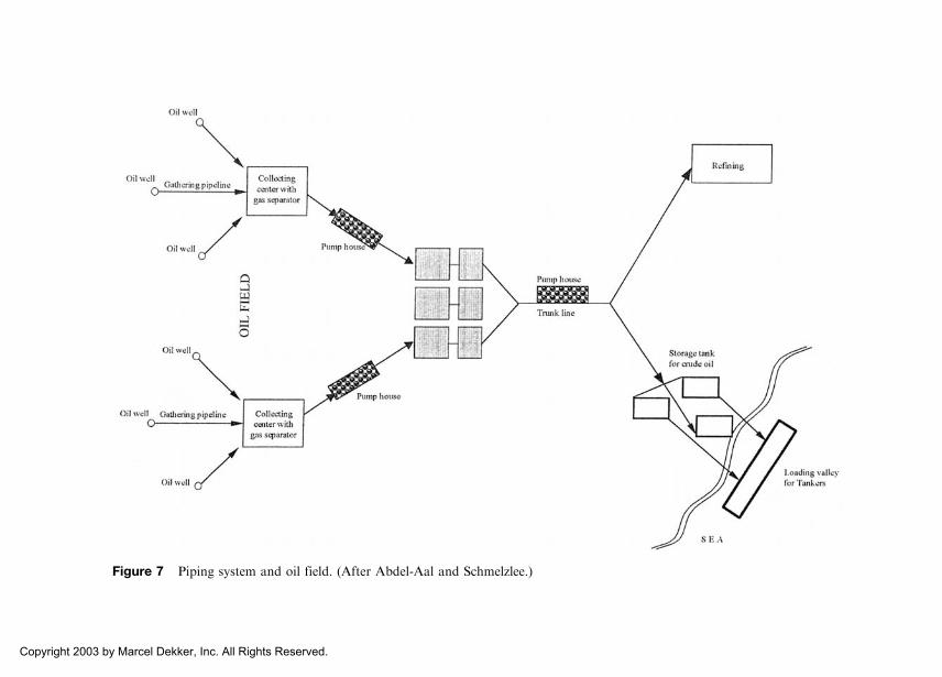
Figure 7 Piping system and oil field. (After Abdel-Aal and Schmelzlee.)
Copyright 2003 by Marcel Dekker, Inc. All Rights Reserved.
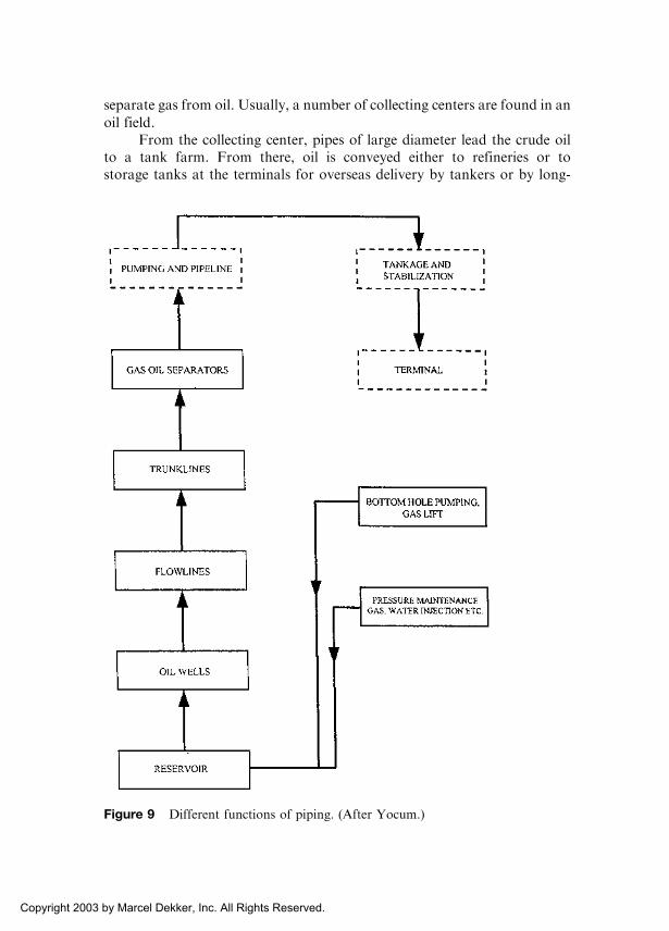
separate gas from oil. Usually, a number of collecting centers are found in an
oil field.From the collecting center, pipes of large diameter lead the crude oil
to a tank farm. From there, oil is conveyed either to refineries or tostorage tanks at the terminals for overseas delivery by tankers or by long-
Figure 9 Different functions of piping. (After Yocum.)
Copyright 2003 by Marcel Dekker, Inc. All Rights Reserved.
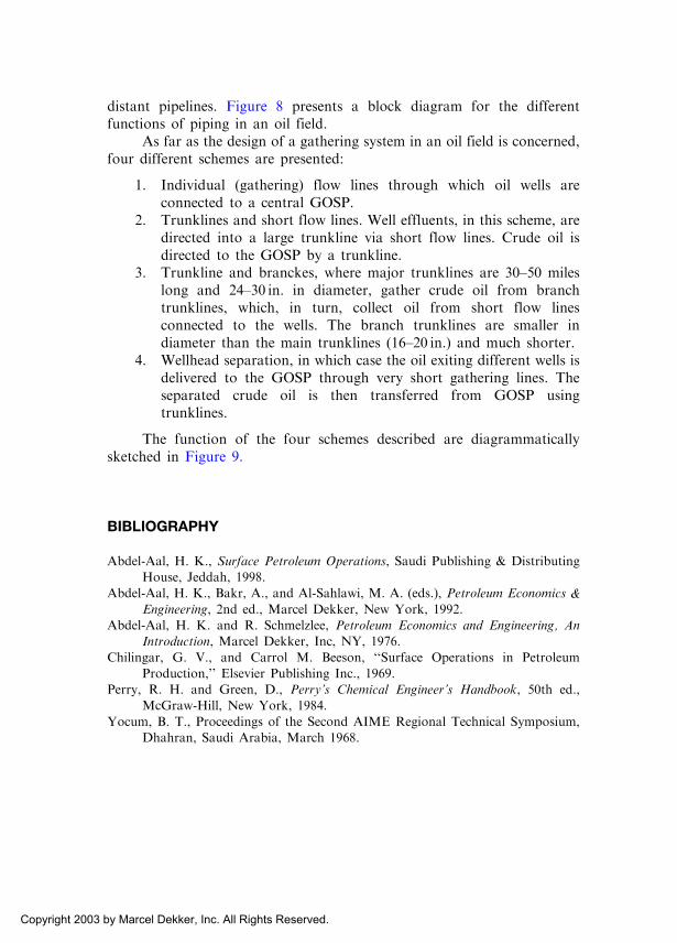
distant pipelines. Figure 8 presents a block diagram for the differentfunctions of piping in an oil field.
As far as the design of a gathering system in an oil field is concerned,four different schemes are presented:
1. Individual (gathering) flow lines through which oil wells areconnected to a central GOSP.
2. Trunklines and short flow lines. Well effluents, in this scheme, aredirected into a large trunkline via short flow lines. Crude oil isdirected to the GOSP by a trunkline.
3. Trunkline and branckes, where major trunklines are 30–50 mileslong and 24–30 in. in diameter, gather crude oil from branchtrunklines, which, in turn, collect oil from short flow linesconnected to the wells. The branch trunklines are smaller indiameter than the main trunklines (16–20 in.) and much shorter.
4. Wellhead separation, in which case the oil exiting different wells isdelivered to the GOSP through very short gathering lines. Theseparated crude oil is then transferred from GOSP usingtrunklines.
The function of the four schemes described are diagrammaticallysketched in Figure 9.
BIBLIOGRAPHY
Abdel-Aal, H. K., Surface Petroleum Operations, Saudi Publishing & Distributing
House, Jeddah, 1998.
Abdel-Aal, H. K., Bakr, A., and Al-Sahlawi, M. A. (eds.), Petroleum Economics &
Engineering, 2nd ed., Marcel Dekker, New York, 1992.
Abdel-Aal, H. K. and R. Schmelzlee, Petroleum Economics and Engineering, An
Introduction, Marcel Dekker, Inc, NY, 1976.
Chilingar, G. V., and Carrol M. Beeson, ‘‘Surface Operations in Petroleum
Production,’’ Elsevier Publishing Inc., 1969.
Perry, R. H. and Green, D., Perry’s Chemical Engineer’s Handbook, 50th ed.,
McGraw-Hill, New York, 1984.
Yocum, B. T., Proceedings of the Second AIME Regional Technical Symposium,
Dhahran, Saudi Arabia, March 1968.
Copyright 2003 by Marcel Dekker, Inc. All Rights Reserved.

REVIEW QUESTIONS
1. List the different types of storage tank.2. What is the difference between floating-roof tanks and fixed-roof
tanks? Which one requires the installation of a vapor recovery unit?Why?
3. A small field has 20 producing wells, each well produces an average of8000 bbl/day. Determine the required field storage capacity and thenumber of storage tanks needed.
4. Describe the five types of storage-tank loss.5. What effects does vapor loss have on the stored crude oil?6. Under what conditions should a vapor recovery unit be included in
field facilities? Why?7. What are the main functions of vapor recovery units?8. Describe briefly the four methods used for vapor recovery.9. What are the main functions of the vapor regulator in a vapor
recovery unit?
Copyright 2003 by Marcel Dekker, Inc. All Rights Reserved.