storagetek lto half-height scsi tape drive - oracle · storagetek lto half-height scsi tape drive...
TRANSCRIPT
Submit comments about this document to [email protected].
StorageTek LTOHalf-Height SCSI Tape Drive
User Guide
LTO
Part Number: E38509-01Release Date: February 2013

StorageTek LTO Half-Height SCSI Tape Drive User Guide
E38509-01
Oracle welcomes your comments and suggestions for improving this book. Contact us at [email protected]. Please include the title, part number, issue date, and revision.
Copyright © 2013 Oracle and/or its affiliates. All rights reserved.
This software and related documentation are provided under a license agreement containing restrictions on use and disclosure and are protected by intellectual property laws. Except as expressly permitted in your license agreement or allowed by law, you may not use, copy, reproduce, translate, broadcast, modify, license, transmit, distribute, exhibit, perform, publish, or display any part, in any form, or by any means. Reverse engineering, disassembly, or decompilation of this software, unless required by law for interoperability, is prohibited.
The information contained herein is subject to change without notice and is not warranted to be error-free. If you find any errors, please report them to us in writing.
If this is software or related software documentation that is delivered to the U.S. Government or anyone licensing it on behalf of the U.S. Government, the following notice is applicable:
U.S. GOVERNMENT RIGHTS Programs, software, databases, and related documentation and technical data delivered to U.S. Government customers are "commercial computer software" or "commercial technical data" pursuant to the applicable Federal Acquisition Regulation and agency-specific supplemental regulations. As such, the use, duplication, disclosure, modification, and adaptation shall be subject to the restrictions and license terms set forth in the applicable Government contract, and, to the extent applicable by the terms of the Government contract, the additional rights set forth in FAR 52.227-19, Commercial Computer Software License (December 2007). Oracle USA, Inc., 500 Oracle Parkway, Redwood City, CA 94065.
This software or hardware is developed for general use in a variety of information management applications. It is not developed or intended for use in any inherently dangerous applications, including applications which may create a risk of personal injury. If you use this software or hardware in dangerous applications, then you shall be responsible to take all appropriate fail-safe, backup, redundancy, and other measures to ensure the safe use. Oracle Corporation and its affiliates disclaim any liability for any damages caused by use of this software or hardware in dangerous applications.
Oracle is a registered trademark of Oracle Corporation and/or its affiliates. Oracle and Java are registered trademarks of Oracle and/or its affiliates. Other names may be trademarks of their respective owners.
AMD, Opteron, the AMD logo, and the AMD Opteron logo are trademarks or registered trademarks of Advanced Micro Devices. Intel and Intel Xeon are trademarks or registered trademarks of Intel Corporation. All SPARC trademarks are used under license and are trademarks or registered trademarks of SPARC International, Inc. UNIX is a registered trademark licensed through X/Open Company, Ltd.
This software or hardware and documentation may provide access to or information on content, products, and services from third parties. Oracle Corporation and its affiliates are not responsible for and expressly disclaim all warranties of any kind with respect to third-party content, products, and services. Oracle Corporation and its affiliates will not be responsible for any loss, costs, or damages incurred due to your access to or use of third-party content, products, or services.
ContentsAbout this guide..............................................................................................5
Intended audience. . . . . . . . . . . . . . . . . . . . . . . . . . . . . . . . . . . . . . . . . . . . . . . . . . . . . . . . . . . . . . . . . . . . . . . . . . . . . . . . . . . . . . . . . . . . . . . . . . . . . . . . . . . . . . . . . . . . . . 5Document conventions and symbols. . . . . . . . . . . . . . . . . . . . . . . . . . . . . . . . . . . . . . . . . . . . . . . . . . . . . . . . . . . . . . . . . . . . . . . . . . . . . . . . . . . . . . . . . . . . . . . . . 5Technical support. . . . . . . . . . . . . . . . . . . . . . . . . . . . . . . . . . . . . . . . . . . . . . . . . . . . . . . . . . . . . . . . . . . . . . . . . . . . . . . . . . . . . . . . . . . . . . . . . . . . . . . . . . . . . . . . . . . . . . . 5Websites. . . . . . . . . . . . . . . . . . . . . . . . . . . . . . . . . . . . . . . . . . . . . . . . . . . . . . . . . . . . . . . . . . . . . . . . . . . . . . . . . . . . . . . . . . . . . . . . . . . . . . . . . . . . . . . . . . . . . . . . . . . . . . . . . 6
1 Before you start.............................................................................................7Supported models. . . . . . . . . . . . . . . . . . . . . . . . . . . . . . . . . . . . . . . . . . . . . . . . . . . . . . . . . . . . . . . . . . . . . . . . . . . . . . . . . . . . . . . . . . . . . . . . . . . . . . . . . . . . . . . . . . . . . . 7Which operating systems are supported?. . . . . . . . . . . . . . . . . . . . . . . . . . . . . . . . . . . . . . . . . . . . . . . . . . . . . . . . . . . . . . . . . . . . . . . . . . . . . . . . . . . . . . . . . . . . 7How do I connect the drive to my server?. . . . . . . . . . . . . . . . . . . . . . . . . . . . . . . . . . . . . . . . . . . . . . . . . . . . . . . . . . . . . . . . . . . . . . . . . . . . . . . . . . . . . . . . . . . 8
Internal drives. . . . . . . . . . . . . . . . . . . . . . . . . . . . . . . . . . . . . . . . . . . . . . . . . . . . . . . . . . . . . . . . . . . . . . . . . . . . . . . . . . . . . . . . . . . . . . . . . . . . . . . . . . . . . . . . . . . . . 8External drives. . . . . . . . . . . . . . . . . . . . . . . . . . . . . . . . . . . . . . . . . . . . . . . . . . . . . . . . . . . . . . . . . . . . . . . . . . . . . . . . . . . . . . . . . . . . . . . . . . . . . . . . . . . . . . . . . . . . . 8
Why is the SCSI bus type important?. . . . . . . . . . . . . . . . . . . . . . . . . . . . . . . . . . . . . . . . . . . . . . . . . . . . . . . . . . . . . . . . . . . . . . . . . . . . . . . . . . . . . . . . . . . . . . . . 8Power specifications. . . . . . . . . . . . . . . . . . . . . . . . . . . . . . . . . . . . . . . . . . . . . . . . . . . . . . . . . . . . . . . . . . . . . . . . . . . . . . . . . . . . . . . . . . . . . . . . . . . . . . . . . . . . . . . . . . . . 9Usage models. . . . . . . . . . . . . . . . . . . . . . . . . . . . . . . . . . . . . . . . . . . . . . . . . . . . . . . . . . . . . . . . . . . . . . . . . . . . . . . . . . . . . . . . . . . . . . . . . . . . . . . . . . . . . . . . . . . . . . . . . . . 9
Other usage models. . . . . . . . . . . . . . . . . . . . . . . . . . . . . . . . . . . . . . . . . . . . . . . . . . . . . . . . . . . . . . . . . . . . . . . . . . . . . . . . . . . . . . . . . . . . . . . . . . . . . . . . . . . . . . 10Solaris drivers. . . . . . . . . . . . . . . . . . . . . . . . . . . . . . . . . . . . . . . . . . . . . . . . . . . . . . . . . . . . . . . . . . . . . . . . . . . . . . . . . . . . . . . . . . . . . . . . . . . . . . . . . . . . . . . . . . . . . . . . . . 10Backup software. . . . . . . . . . . . . . . . . . . . . . . . . . . . . . . . . . . . . . . . . . . . . . . . . . . . . . . . . . . . . . . . . . . . . . . . . . . . . . . . . . . . . . . . . . . . . . . . . . . . . . . . . . . . . . . . . . . . . . . 10
2 Installing an internal LTO SCSI tape drive.............................................11Check the internal drive's SCSI ID. . . . . . . . . . . . . . . . . . . . . . . . . . . . . . . . . . . . . . . . . . . . . . . . . . . . . . . . . . . . . . . . . . . . . . . . . . . . . . . . . . . . . . . . . . . . . . . . . . 11Prepare mounting bay. . . . . . . . . . . . . . . . . . . . . . . . . . . . . . . . . . . . . . . . . . . . . . . . . . . . . . . . . . . . . . . . . . . . . . . . . . . . . . . . . . . . . . . . . . . . . . . . . . . . . . . . . . . . . . . . 12Attach mounting hardware. . . . . . . . . . . . . . . . . . . . . . . . . . . . . . . . . . . . . . . . . . . . . . . . . . . . . . . . . . . . . . . . . . . . . . . . . . . . . . . . . . . . . . . . . . . . . . . . . . . . . . . . . . 12Install drive. . . . . . . . . . . . . . . . . . . . . . . . . . . . . . . . . . . . . . . . . . . . . . . . . . . . . . . . . . . . . . . . . . . . . . . . . . . . . . . . . . . . . . . . . . . . . . . . . . . . . . . . . . . . . . . . . . . . . . . . . . . . 13Connect SCSI and power cables. . . . . . . . . . . . . . . . . . . . . . . . . . . . . . . . . . . . . . . . . . . . . . . . . . . . . . . . . . . . . . . . . . . . . . . . . . . . . . . . . . . . . . . . . . . . . . . . . . . . . 14
Where should the SCSI terminator be?. . . . . . . . . . . . . . . . . . . . . . . . . . . . . . . . . . . . . . . . . . . . . . . . . . . . . . . . . . . . . . . . . . . . . . . . . . . . . . . . . . . . . . . . 15Secure the drive. . . . . . . . . . . . . . . . . . . . . . . . . . . . . . . . . . . . . . . . . . . . . . . . . . . . . . . . . . . . . . . . . . . . . . . . . . . . . . . . . . . . . . . . . . . . . . . . . . . . . . . . . . . . . . . . . . . . . . . 16Reboot the server. . . . . . . . . . . . . . . . . . . . . . . . . . . . . . . . . . . . . . . . . . . . . . . . . . . . . . . . . . . . . . . . . . . . . . . . . . . . . . . . . . . . . . . . . . . . . . . . . . . . . . . . . . . . . . . . . . . . . . 16
3 Installing an external LTO SCSI tape drive............................................19Check the external drive's SCSI ID. . . . . . . . . . . . . . . . . . . . . . . . . . . . . . . . . . . . . . . . . . . . . . . . . . . . . . . . . . . . . . . . . . . . . . . . . . . . . . . . . . . . . . . . . . . . . . . . . . 19Connect the SCSI cable. . . . . . . . . . . . . . . . . . . . . . . . . . . . . . . . . . . . . . . . . . . . . . . . . . . . . . . . . . . . . . . . . . . . . . . . . . . . . . . . . . . . . . . . . . . . . . . . . . . . . . . . . . . . . . . 20
Does the tape drive need a terminator?. . . . . . . . . . . . . . . . . . . . . . . . . . . . . . . . . . . . . . . . . . . . . . . . . . . . . . . . . . . . . . . . . . . . . . . . . . . . . . . . . . . . . . . 20Connect the power cable. . . . . . . . . . . . . . . . . . . . . . . . . . . . . . . . . . . . . . . . . . . . . . . . . . . . . . . . . . . . . . . . . . . . . . . . . . . . . . . . . . . . . . . . . . . . . . . . . . . . . . . . . . . . . 21Reboot the server. . . . . . . . . . . . . . . . . . . . . . . . . . . . . . . . . . . . . . . . . . . . . . . . . . . . . . . . . . . . . . . . . . . . . . . . . . . . . . . . . . . . . . . . . . . . . . . . . . . . . . . . . . . . . . . . . . . . . . 21
4 Verify installation.......................................................................................235 Understanding the LEDs..........................................................................25
Your StorageTek LTO tape drive. . . . . . . . . . . . . . . . . . . . . . . . . . . . . . . . . . . . . . . . . . . . . . . . . . . . . . . . . . . . . . . . . . . . . . . . . . . . . . . . . . . . . . . . . . . . . . . . . . . . . 25Understanding LED sequences. . . . . . . . . . . . . . . . . . . . . . . . . . . . . . . . . . . . . . . . . . . . . . . . . . . . . . . . . . . . . . . . . . . . . . . . . . . . . . . . . . . . . . . . . . . . . . . . . . . . . . 25
6 Operating your tape drive........................................................................29Loading a cartridge. . . . . . . . . . . . . . . . . . . . . . . . . . . . . . . . . . . . . . . . . . . . . . . . . . . . . . . . . . . . . . . . . . . . . . . . . . . . . . . . . . . . . . . . . . . . . . . . . . . . . . . . . . . . . . . . . . . 29Unloading a cartridge. . . . . . . . . . . . . . . . . . . . . . . . . . . . . . . . . . . . . . . . . . . . . . . . . . . . . . . . . . . . . . . . . . . . . . . . . . . . . . . . . . . . . . . . . . . . . . . . . . . . . . . . . . . . . . . . . 29Removing power from the drive. . . . . . . . . . . . . . . . . . . . . . . . . . . . . . . . . . . . . . . . . . . . . . . . . . . . . . . . . . . . . . . . . . . . . . . . . . . . . . . . . . . . . . . . . . . . . . . . . . . . 30
7 Use the correct media................................................................................31Ordering media. . . . . . . . . . . . . . . . . . . . . . . . . . . . . . . . . . . . . . . . . . . . . . . . . . . . . . . . . . . . . . . . . . . . . . . . . . . . . . . . . . . . . . . . . . . . . . . . . . . . . . . . . . . . . . . . . . . . . . . . 31Cartridges. . . . . . . . . . . . . . . . . . . . . . . . . . . . . . . . . . . . . . . . . . . . . . . . . . . . . . . . . . . . . . . . . . . . . . . . . . . . . . . . . . . . . . . . . . . . . . . . . . . . . . . . . . . . . . . . . . . . . . . . . . . . . . 31
Data cartridges. . . . . . . . . . . . . . . . . . . . . . . . . . . . . . . . . . . . . . . . . . . . . . . . . . . . . . . . . . . . . . . . . . . . . . . . . . . . . . . . . . . . . . . . . . . . . . . . . . . . . . . . . . . . . . . . . . . 31Cleaning cartridges. . . . . . . . . . . . . . . . . . . . . . . . . . . . . . . . . . . . . . . . . . . . . . . . . . . . . . . . . . . . . . . . . . . . . . . . . . . . . . . . . . . . . . . . . . . . . . . . . . . . . . . . . . . . . . 31
WORM data cartridges. . . . . . . . . . . . . . . . . . . . . . . . . . . . . . . . . . . . . . . . . . . . . . . . . . . . . . . . . . . . . . . . . . . . . . . . . . . . . . . . . . . . . . . . . . . . . . . . . . . . . . . . . . . . . . . 31Write protecting cartridges. . . . . . . . . . . . . . . . . . . . . . . . . . . . . . . . . . . . . . . . . . . . . . . . . . . . . . . . . . . . . . . . . . . . . . . . . . . . . . . . . . . . . . . . . . . . . . . . . . . . . . . . . . . 32Cleaning the tape drive. . . . . . . . . . . . . . . . . . . . . . . . . . . . . . . . . . . . . . . . . . . . . . . . . . . . . . . . . . . . . . . . . . . . . . . . . . . . . . . . . . . . . . . . . . . . . . . . . . . . . . . . . . . . . . . 32Handling cartridges. . . . . . . . . . . . . . . . . . . . . . . . . . . . . . . . . . . . . . . . . . . . . . . . . . . . . . . . . . . . . . . . . . . . . . . . . . . . . . . . . . . . . . . . . . . . . . . . . . . . . . . . . . . . . . . . . . . 33
StorageTek LTO Half-Height SCSI Tape Drive 3

Operating and storage environment. . . . . . . . . . . . . . . . . . . . . . . . . . . . . . . . . . . . . . . . . . . . . . . . . . . . . . . . . . . . . . . . . . . . . . . . . . . . . . . . . . . . . . . . . . . . . 33
8 Troubleshooting.......................................................................................35General procedure. . . . . . . . . . . . . . . . . . . . . . . . . . . . . . . . . . . . . . . . . . . . . . . . . . . . . . . . . . . . . . . . . . . . . . . . . . . . . . . . . . . . . . . . . . . . . . . . . . . . . . . . . . . . . . . . . 35Optimizing performance. . . . . . . . . . . . . . . . . . . . . . . . . . . . . . . . . . . . . . . . . . . . . . . . . . . . . . . . . . . . . . . . . . . . . . . . . . . . . . . . . . . . . . . . . . . . . . . . . . . . . . . . . . 36
Is the tape drive on a dedicated SCSI bus?. . . . . . . . . . . . . . . . . . . . . . . . . . . . . . . . . . . . . . . . . . . . . . . . . . . . . . . . . . . . . . . . . . . . . . . . . . . . . . . . . 36Can your system deliver the required performance?. . . . . . . . . . . . . . . . . . . . . . . . . . . . . . . . . . . . . . . . . . . . . . . . . . . . . . . . . . . . . . . . . . . . . 36
Problems with cartridges. . . . . . . . . . . . . . . . . . . . . . . . . . . . . . . . . . . . . . . . . . . . . . . . . . . . . . . . . . . . . . . . . . . . . . . . . . . . . . . . . . . . . . . . . . . . . . . . . . . . . . . . . . 37The cartridge is jammed. . . . . . . . . . . . . . . . . . . . . . . . . . . . . . . . . . . . . . . . . . . . . . . . . . . . . . . . . . . . . . . . . . . . . . . . . . . . . . . . . . . . . . . . . . . . . . . . . . . . . . 37The drive will not accept the cartridge (or ejects it immediately). . . . . . . . . . . . . . . . . . . . . . . . . . . . . . . . . . . . . . . . . . . . . . . . . . . . . . . 37
A SCSI configuration guide......................................................................39SCSI in LTO devices. . . . . . . . . . . . . . . . . . . . . . . . . . . . . . . . . . . . . . . . . . . . . . . . . . . . . . . . . . . . . . . . . . . . . . . . . . . . . . . . . . . . . . . . . . . . . . . . . . . . . . . . . . . . . . . . 39
Daisy chaining devices. . . . . . . . . . . . . . . . . . . . . . . . . . . . . . . . . . . . . . . . . . . . . . . . . . . . . . . . . . . . . . . . . . . . . . . . . . . . . . . . . . . . . . . . . . . . . . . . . . . . . . . 39SCSI terminology. . . . . . . . . . . . . . . . . . . . . . . . . . . . . . . . . . . . . . . . . . . . . . . . . . . . . . . . . . . . . . . . . . . . . . . . . . . . . . . . . . . . . . . . . . . . . . . . . . . . . . . . . . . . . . . . . . . 39Setting up the SCSI bus. . . . . . . . . . . . . . . . . . . . . . . . . . . . . . . . . . . . . . . . . . . . . . . . . . . . . . . . . . . . . . . . . . . . . . . . . . . . . . . . . . . . . . . . . . . . . . . . . . . . . . . . . . . . 39
SCSI ID numbers. . . . . . . . . . . . . . . . . . . . . . . . . . . . . . . . . . . . . . . . . . . . . . . . . . . . . . . . . . . . . . . . . . . . . . . . . . . . . . . . . . . . . . . . . . . . . . . . . . . . . . . . . . . . . . 39Identifying SCSI IDs. . . . . . . . . . . . . . . . . . . . . . . . . . . . . . . . . . . . . . . . . . . . . . . . . . . . . . . . . . . . . . . . . . . . . . . . . . . . . . . . . . . . . . . . . . . . . . . . . . . . . . . . . . . . . . . 40Setting the SCSI ID on LTO drives. . . . . . . . . . . . . . . . . . . . . . . . . . . . . . . . . . . . . . . . . . . . . . . . . . . . . . . . . . . . . . . . . . . . . . . . . . . . . . . . . . . . . . . . . . . . . . . 40SCSI termination. . . . . . . . . . . . . . . . . . . . . . . . . . . . . . . . . . . . . . . . . . . . . . . . . . . . . . . . . . . . . . . . . . . . . . . . . . . . . . . . . . . . . . . . . . . . . . . . . . . . . . . . . . . . . . . . . . . 40
Internal drives. . . . . . . . . . . . . . . . . . . . . . . . . . . . . . . . . . . . . . . . . . . . . . . . . . . . . . . . . . . . . . . . . . . . . . . . . . . . . . . . . . . . . . . . . . . . . . . . . . . . . . . . . . . . . . . . . 40External drives. . . . . . . . . . . . . . . . . . . . . . . . . . . . . . . . . . . . . . . . . . . . . . . . . . . . . . . . . . . . . . . . . . . . . . . . . . . . . . . . . . . . . . . . . . . . . . . . . . . . . . . . . . . . . . . . 41
SCSI cables. . . . . . . . . . . . . . . . . . . . . . . . . . . . . . . . . . . . . . . . . . . . . . . . . . . . . . . . . . . . . . . . . . . . . . . . . . . . . . . . . . . . . . . . . . . . . . . . . . . . . . . . . . . . . . . . . . . . . . . . . . 42Cable length. . . . . . . . . . . . . . . . . . . . . . . . . . . . . . . . . . . . . . . . . . . . . . . . . . . . . . . . . . . . . . . . . . . . . . . . . . . . . . . . . . . . . . . . . . . . . . . . . . . . . . . . . . . . . . . . . . . 42Cable quality. . . . . . . . . . . . . . . . . . . . . . . . . . . . . . . . . . . . . . . . . . . . . . . . . . . . . . . . . . . . . . . . . . . . . . . . . . . . . . . . . . . . . . . . . . . . . . . . . . . . . . . . . . . . . . . . . . 42
With internal devices. . . . . . . . . . . . . . . . . . . . . . . . . . . . . . . . . . . . . . . . . . . . . . . . . . . . . . . . . . . . . . . . . . . . . . . . . . . . . . . . . . . . . . . . . . . . . . . . . . . . 42With external devices. . . . . . . . . . . . . . . . . . . . . . . . . . . . . . . . . . . . . . . . . . . . . . . . . . . . . . . . . . . . . . . . . . . . . . . . . . . . . . . . . . . . . . . . . . . . . . . . . . . 42
Note on SE and LVDS interfaces. . . . . . . . . . . . . . . . . . . . . . . . . . . . . . . . . . . . . . . . . . . . . . . . . . . . . . . . . . . . . . . . . . . . . . . . . . . . . . . . . . . . . . . . . . . . 43
Index.............................................................................................................45
4 Contents

About this guideThis guide provides information about:
• Installing the LTO SCSI tape drive
• Using the LTO SCSI tape drive
• Troubleshooting the LTO SCSI tape drive
Intended audienceThis guide is intended for users who install, operate and maintain the LTO tape drive.
Document conventions and symbolsTable 1 Document conventions
ElementConvention
Cross-reference links and e-mail addressesBlue text: (page 5)
website addressesBlue, underlined text: http://www.oracle.com
Bold text • Keys that are pressed• Text typed into a GUI element, such as a box• GUI elements that are clicked or selected, such as menu
and list items, buttons, tabs, and check boxes
Text emphasisItalic text
Monospace text • File and directory names• System output• Code• Commands, their arguments, and argument values
Monospace, italic text • Code variables• Command variables
Emphasized monospace textMonospace, bold text
WARNING! Indicates that failure to follow directions could result in bodily harm or death.
CAUTION: Indicates that failure to follow directions could result in damage to equipment or data.
IMPORTANT: Provides clarifying information or specific instructions.
NOTE: Provides additional information.
Technical supportTelephone numbers for worldwide technical support are listed on the support website: http://www.oracle.com/us/support/contact.html.
Collect the following information before calling:
• Contract number
• Product serial numbers
• Product model names and numbers
• Error messages
StorageTek LTO Half-Height SCSI Tape Drive 5

• Operating system type and revision level
• Detailed questions
For continuous quality improvement, calls may be recorded or monitored.
WebsitesFor additional information, see the following websites:
• http://www.oracle.com — Corporate website
• http://www.oracle.com/us/products/servers-storage/storage/tape-storage/index.html — Storage products
• http://www.oracle.com/us/support/contact.html — Support website
• http://www.oracle.com/technetwork/documentation/tape-storage-curr-187744.html — Products documentation
6

1 Before you startIn this chapter:
• Supported models (page 7)
• Which operating systems are supported? (page 7)
• How do I connect the drive to my server? (page 8)
• Why is the SCSI bus type important? (page 8)
• Power specifications (page 9)
• Usage models (page 9)
• Solaris drivers (page 10)
• Backup software (page 10)
Supported modelsThis guide describes how to install and operate the following LTO tape drive models:
• LTO-4 internal and external tape drives. These are Ultra 320 SCSI devices with a maximum burst transfer speed of 320MB/s. They can write uncompressed data at up to 80 MB/s (288 GB/hour).
• LTO-3 internal and external tape drives. These are Ultra 320 SCSI devices with a maximum burst transfer speed of 320MB/s. They can write uncompressed data at up to 60 MB/s (216 GB/hour).
• LTO-2 internal and external tape drives: These are Ultra 160 SCSI devices with a maximum burst transfer speed of 160MB/s. They can write uncompressed data at up to 24 MB/s (86 GB/hour).
NOTE: The compression ratio is 2:1.
For a detailed product specification, please refer to http://www.oracle.com/us/products/servers-storage/storage/tape-storage/index.html.
5. Drive LED1. Cartridge door
6. Ready LED2. On/Off switch (external drives only)
7. Eject button3. Clean LED
4. Tape LED
Figure 1 Front view of the LTO external tape drive
Which operating systems are supported?LTO tape drives can be connected to servers running under Solaris, Linux and other major operating systems. Refer to http://www.oracle.com for the most recent information about the operating system versions that are supported.
StorageTek LTO Half-Height SCSI Tape Drive 7

How do I connect the drive to my server?Check the usage models on Usage models (page 9). This shows how the LTO tape drive can be used in different systemarchitectures.
The following guidelines apply:
• You will need a properly installed and configured SCSI host bus adapter (HBA) or a built-in SCSI controller on yourserver and a suitable SCSI cable. See also Why is the SCSI bus type important? (page 8).
• For optimum performance the drive should be the only device on the SCSI bus.
• Always terminate the SCSI bus. LTO internal tape drives require terminators; external drives are auto terminating aslong as they are on a dedicated SCSI bus or the last device on a chain.
• Do not attach the drive to the same SCSI bus as your disk drive or to a RAID controller.
Internal drivesThe tape drive is installed into a spare, industry-standard, 5¼-inch, half-height drive bay in your server and is attached tothe SCSI bus of the host server. Use an LVDS-compatible ribbon cable to connect the tape drive to a spare 68-pin, high density(HD68), wide SCSI connector on the host server. The cable must be terminated.
See also Installing an internal tape drive (page 11).
External drivesA 68-pin, wide, VHDCI-to-HD68 SCSI cable is required to attach the tape drive to the host server. See also Installing anexternal tape drive (page 19).
Why is the SCSI bus type important?The SCSI bus type determines the speed at which data can be transferred between devices on the bus and the maximumlength of cable that can be used. LTO-4 and LTO-3 drives support a burst transfer rate of 320 MB/sec. LTO-2 drives supporta burst transfer rate of 160 MB/sec. To benefit from this level of performance, it is important to ensure that the drives areconnected to a SCSI bus of a similar or higher specification. This means that you need:
• An Ultra320 bus for LTO-4 and LTO-3 drives. An Ultra160 or Ultra320 SCSI bus for LTO-2 drives. If you attach thedrive to a lower specification SCSI bus, it may still work but will transfer data at a lower speed.
• LVDS-rated SCSI cabling and terminators. The LVDS interface enables the data to be transferred at the drive'smaximum rate.
Table 2 Supported SCSI bus types
SupportedSCSI Bus Type
Yes. This is a recommended configuration for all LTO tape drives.Do not daisy chain LTO–4 or LTO–3 tape drives because performance may be degraded.Do not daisy chain LTO-2 tape drives with Ultra320 devices.
Ultra320 LVDS
Yes. This is a recommended configuration for LTO-2 tape drives. It is an acceptableconfiguration for LTO–4 and LTO–3 tape drives, but it could limit performance on theLTO–4 tape drive.Up to two LTO-2 tape drives may be daisy-chained. Do not daisy-chain LTO–4 or LTO–3tape drives.
Ultra160 LVDS
Yes. This is acceptable for one LTO-2 drive per bus.Do not use with LTO–4 or LTO–3 tape drives and do not daisy-chain LTO-2 tape drives.
Ultra2 LVDS
These are not recommended configurations because they will restrict performance.Ultra wide LVDSand single-ended
No. This will severely restrict performance and you would need a suitable cable or adapter.Ultra narrow,single-ended
No. The drive will not work and you may damage the drive or controller.High VoltageDifferential
8 Before you start

Power specificationsFor a detailed product specification, please refer to http://www.oracle.com/us/products/servers-storage/storage/tape-storage/index.html.
Table 3 Power specifications
All LTO half-height tape drives
13 Watts idle,Power consumption26 Watts typical,40 Watts maximum
+5V @ 1.9A typicalPower requirements+5V @ 3.9A maximum+12V @ 0.7A typical+12V @ 2.5A maximum
100–240 VAC, 50-60 Hz, auto-ranging, 0.7A maximumPowerrequirements,externaltape drives
Usage modelsLTO tape drives can be used in a standalone or network environment. However, they should always be directly attached to asuitable SCSI connector on the storage server.
ServerA
Tape driveB
Figure 2 Usage model
The following table shows the recommended usage models and Optimizing performance (page 36) provides further informationabout factors that can affect performance.
StorageTek LTO Half-Height SCSI Tape Drive 9
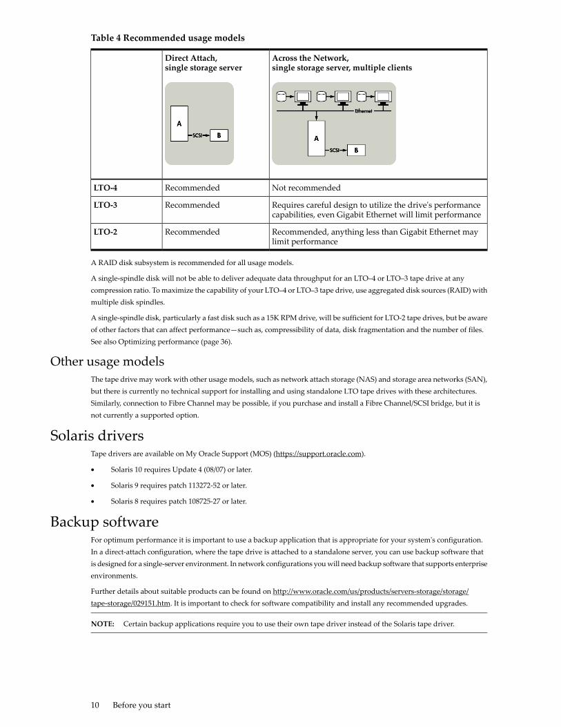
Table 4 Recommended usage models
Across the Network,single storage server, multiple clients
Direct Attach,single storage server
Not recommendedRecommendedLTO-4
Requires careful design to utilize the drive's performancecapabilities, even Gigabit Ethernet will limit performance
RecommendedLTO-3
Recommended, anything less than Gigabit Ethernet maylimit performance
RecommendedLTO-2
A RAID disk subsystem is recommended for all usage models.
A single-spindle disk will not be able to deliver adequate data throughput for an LTO–4 or LTO–3 tape drive at anycompression ratio. To maximize the capability of your LTO–4 or LTO–3 tape drive, use aggregated disk sources (RAID) withmultiple disk spindles.
A single-spindle disk, particularly a fast disk such as a 15K RPM drive, will be sufficient for LTO-2 tape drives, but be awareof other factors that can affect performance—such as, compressibility of data, disk fragmentation and the number of files.See also Optimizing performance (page 36).
Other usage modelsThe tape drive may work with other usage models, such as network attach storage (NAS) and storage area networks (SAN),but there is currently no technical support for installing and using standalone LTO tape drives with these architectures.Similarly, connection to Fibre Channel may be possible, if you purchase and install a Fibre Channel/SCSI bridge, but it isnot currently a supported option.
Solaris driversTape drivers are available on My Oracle Support (MOS) (https://support.oracle.com).
• Solaris 10 requires Update 4 (08/07) or later.
• Solaris 9 requires patch 113272-52 or later.
• Solaris 8 requires patch 108725-27 or later.
Backup softwareFor optimum performance it is important to use a backup application that is appropriate for your system's configuration.In a direct-attach configuration, where the tape drive is attached to a standalone server, you can use backup software thatis designed for a single-server environment. In network configurations you will need backup software that supports enterpriseenvironments.
Further details about suitable products can be found on http://www.oracle.com/us/products/servers-storage/storage/tape-storage/029151.htm. It is important to check for software compatibility and install any recommended upgrades.
NOTE: Certain backup applications require you to use their own tape driver instead of the Solaris tape driver.
10 Before you start
2 Installing an internal LTO SCSI tape driveIf you are installing an external LTO tape drive, refer to Installing an external tape drive (page 19).
• Check the internal drive's SCSI ID (page 11)
• Prepare mounting bay (page 12)
• Attach mounting hardware (page 12)
• Install drive (page 13)
• Attach power and SCSI cables (page 14)
• Secure the drive (page 16)
• Reboot the server (page 16)
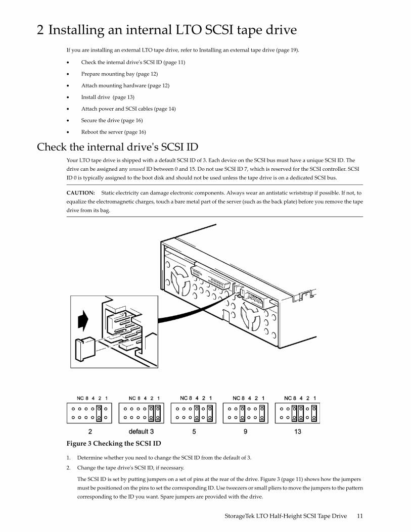
Check the internal drive's SCSI IDYour LTO tape drive is shipped with a default SCSI ID of 3. Each device on the SCSI bus must have a unique SCSI ID. Thedrive can be assigned any unused ID between 0 and 15. Do not use SCSI ID 7, which is reserved for the SCSI controller. SCSIID 0 is typically assigned to the boot disk and should not be used unless the tape drive is on a dedicated SCSI bus.
CAUTION: Static electricity can damage electronic components. Always wear an antistatic wriststrap if possible. If not, toequalize the electromagnetic charges, touch a bare metal part of the server (such as the back plate) before you remove the tapedrive from its bag.
Figure 3 Checking the SCSI ID
1. Determine whether you need to change the SCSI ID from the default of 3.
2. Change the tape drive's SCSI ID, if necessary.
The SCSI ID is set by putting jumpers on a set of pins at the rear of the drive. Figure 3 (page 11) shows how the jumpersmust be positioned on the pins to set the corresponding ID. Use tweezers or small pliers to move the jumpers to the patterncorresponding to the ID you want. Spare jumpers are provided with the drive.
StorageTek LTO Half-Height SCSI Tape Drive 11
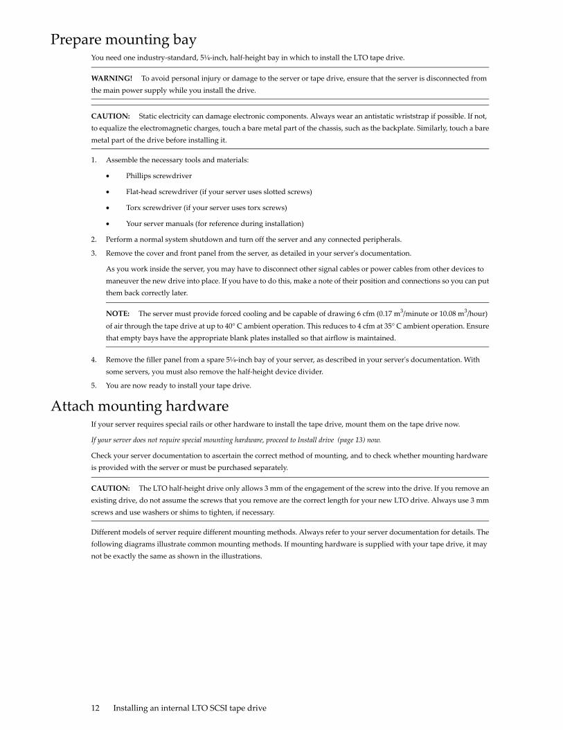
Prepare mounting bayYou need one industry-standard, 5¼-inch, half-height bay in which to install the LTO tape drive.
WARNING! To avoid personal injury or damage to the server or tape drive, ensure that the server is disconnected fromthe main power supply while you install the drive.
CAUTION: Static electricity can damage electronic components. Always wear an antistatic wriststrap if possible. If not,to equalize the electromagnetic charges, touch a bare metal part of the chassis, such as the backplate. Similarly, touch a baremetal part of the drive before installing it.
1. Assemble the necessary tools and materials:
• Phillips screwdriver
• Flat-head screwdriver (if your server uses slotted screws)
• Torx screwdriver (if your server uses torx screws)
• Your server manuals (for reference during installation)
2. Perform a normal system shutdown and turn off the server and any connected peripherals.
3. Remove the cover and front panel from the server, as detailed in your server's documentation.
As you work inside the server, you may have to disconnect other signal cables or power cables from other devices tomaneuver the new drive into place. If you have to do this, make a note of their position and connections so you can putthem back correctly later.
NOTE: The server must provide forced cooling and be capable of drawing 6 cfm (0.17 m3/minute or 10.08 m3/hour)
of air through the tape drive at up to 40° C ambient operation. This reduces to 4 cfm at 35° C ambient operation. Ensurethat empty bays have the appropriate blank plates installed so that airflow is maintained.
4. Remove the filler panel from a spare 5¼-inch bay of your server, as described in your server's documentation. Withsome servers, you must also remove the half-height device divider.
5. You are now ready to install your tape drive.
Attach mounting hardwareIf your server requires special rails or other hardware to install the tape drive, mount them on the tape drive now.
If your server does not require special mounting hardware, proceed to Install drive (page 13) now.
Check your server documentation to ascertain the correct method of mounting, and to check whether mounting hardwareis provided with the server or must be purchased separately.
CAUTION: The LTO half-height drive only allows 3 mm of the engagement of the screw into the drive. If you remove anexisting drive, do not assume the screws that you remove are the correct length for your new LTO drive. Always use 3 mmscrews and use washers or shims to tighten, if necessary.
Different models of server require different mounting methods. Always refer to your server documentation for details. Thefollowing diagrams illustrate common mounting methods. If mounting hardware is supplied with your tape drive, it maynot be exactly the same as shown in the illustrations.
12 Installing an internal LTO SCSI tape drive
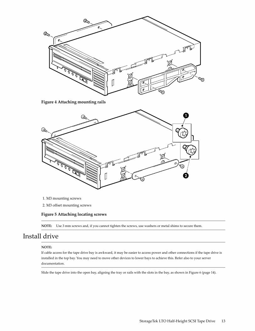
Figure 4 Attaching mounting rails
1. M3 mounting screws
2. M3 offset mounting screws
Figure 5 Attaching locating screws
NOTE: Use 3 mm screws and, if you cannot tighten the screws, use washers or metal shims to secure them.
Install driveNOTE:If cable access for the tape drive bay is awkward, it may be easier to access power and other connections if the tape drive isinstalled in the top bay. You may need to move other devices to lower bays to achieve this. Refer also to your serverdocumentation.
Slide the tape drive into the open bay, aligning the tray or rails with the slots in the bay, as shown in Figure 6 (page 14).
StorageTek LTO Half-Height SCSI Tape Drive 13
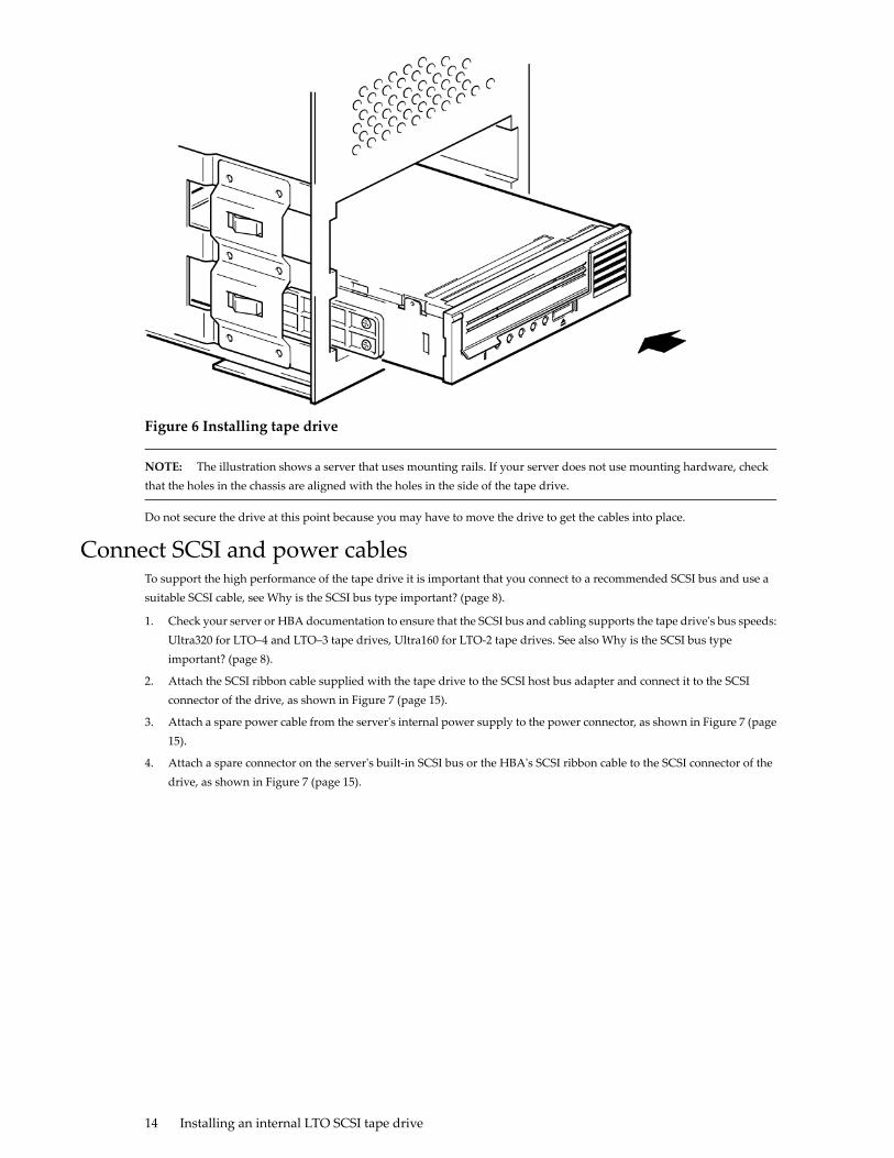
Figure 6 Installing tape drive
NOTE: The illustration shows a server that uses mounting rails. If your server does not use mounting hardware, checkthat the holes in the chassis are aligned with the holes in the side of the tape drive.
Do not secure the drive at this point because you may have to move the drive to get the cables into place.
Connect SCSI and power cablesTo support the high performance of the tape drive it is important that you connect to a recommended SCSI bus and use asuitable SCSI cable, see Why is the SCSI bus type important? (page 8).
1. Check your server or HBA documentation to ensure that the SCSI bus and cabling supports the tape drive's bus speeds:Ultra320 for LTO–4 and LTO–3 tape drives, Ultra160 for LTO-2 tape drives. See also Why is the SCSI bus typeimportant? (page 8).
2. Attach the SCSI ribbon cable supplied with the tape drive to the SCSI host bus adapter and connect it to the SCSIconnector of the drive, as shown in Figure 7 (page 15).
3. Attach a spare power cable from the server's internal power supply to the power connector, as shown in Figure 7 (page15).
4. Attach a spare connector on the server's built-in SCSI bus or the HBA's SCSI ribbon cable to the SCSI connector of thedrive, as shown in Figure 7 (page 15).
14 Installing an internal LTO SCSI tape drive

5. If the drive is the last device on the SCSI chain, make sure that the SCSI cable is terminated correctly.
Daisy-chaining two devices is not recommended. If you were to do so, do not mix drive families (daisy-chain only withother LTO tape drives) and do not daisy chain any Ultra320 devices.
5. server's power supply1. SCSI cable
6. SCSI controller2. power cable
7. terminated SCSI cable3. tape drive
4. power cable
Figure 7 Connecting SCSI and power cables
Where should the SCSI terminator be?Termination must be present at two and ONLY two positions on the SCSI bus—at the beginning of the SCSI bus and at theend of the SCSI bus. Termination is normally enabled by default on the HBA and most internal SCSI cables have a terminatorattached. This will usually be a small, rectangular block of plastic attached to the cable end and marked ‘SCSI Terminator'.
Therefore, assuming the HBA is the first device on the bus, you should check that the second terminator is placed after the lastdevice, as shown in Figure 7 (page 15), item 7.
StorageTek LTO Half-Height SCSI Tape Drive 15

Secure the drive1. Secure the drive, as described in your server documentation. The following diagrams are examples only.
Plastic rail1
Server latch2
Figure 8 Securing drive, mounting hardware used
M3 screws1
Figure 9 Securing drive, no mounting hardware used
NOTE: Use 3 mm screws and, if you cannot tighten the screws, use washers to secure them.
2. Ensure blank plates are in place over empty bays and replace the cover on the server.
Reboot the serverReboot the server to power up the tape drive and server.
Watch the boot screen carefully after installation. If there are any errors or unexpected messages go back and check the SCSIcabling carefully.
• Have you installed the correct SCSI cable?
• Have you reconnected all devices securely?
16 Installing an internal LTO SCSI tape drive

If this does not resolve the problem, refer to Troubleshooting (page 35) for further guidelines.
StorageTek LTO Half-Height SCSI Tape Drive 17

18
3 Installing an external LTO SCSI tape driveIf you are installing an internal LTO tape drive, please refer to Installing an internal tape drive (page 11).
In this chapter:
• Check the external drive's SCSI ID (page 19)
• Connect the SCSI cable (page 20)
• Connect the power cable (page 21)
• Reboot the server (page 21)
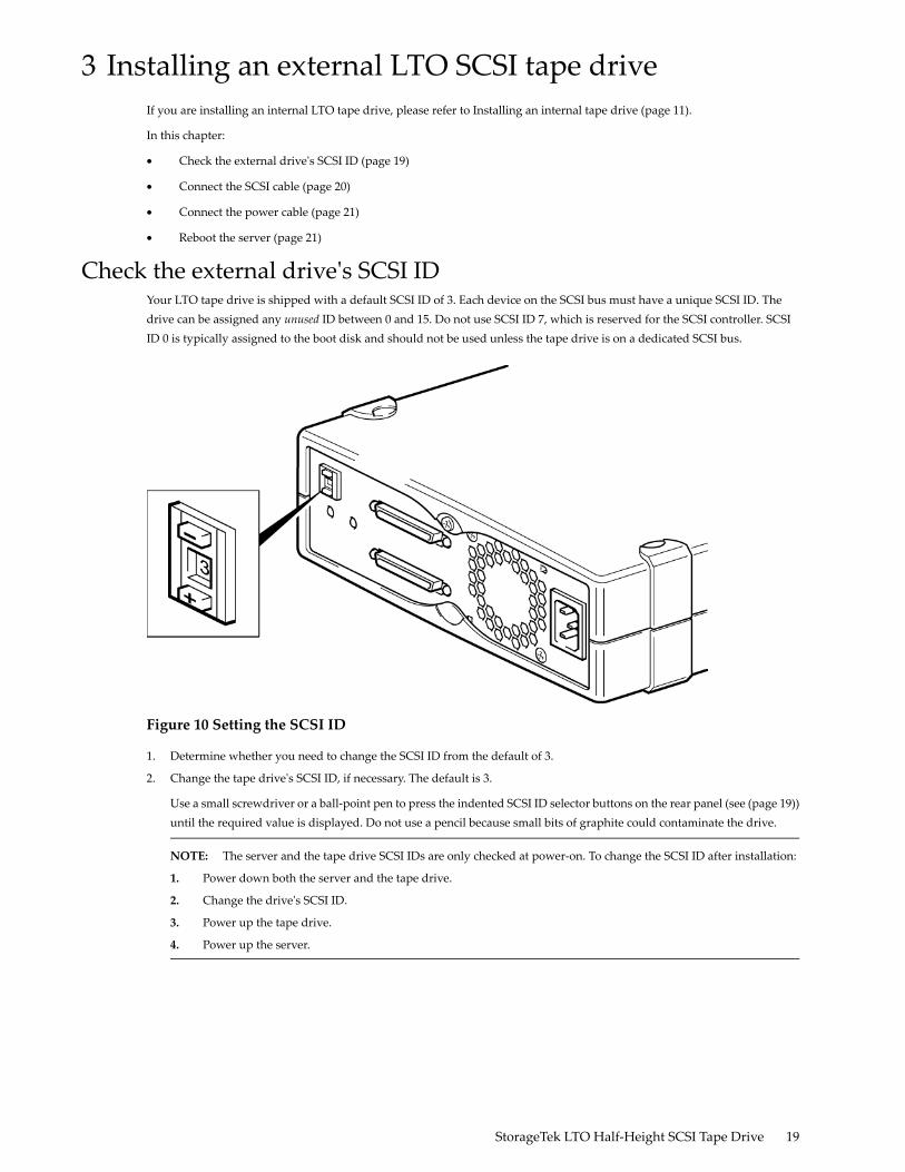
Check the external drive's SCSI IDYour LTO tape drive is shipped with a default SCSI ID of 3. Each device on the SCSI bus must have a unique SCSI ID. Thedrive can be assigned any unused ID between 0 and 15. Do not use SCSI ID 7, which is reserved for the SCSI controller. SCSIID 0 is typically assigned to the boot disk and should not be used unless the tape drive is on a dedicated SCSI bus.
Figure 10 Setting the SCSI ID
1. Determine whether you need to change the SCSI ID from the default of 3.
2. Change the tape drive's SCSI ID, if necessary. The default is 3.
Use a small screwdriver or a ball-point pen to press the indented SCSI ID selector buttons on the rear panel (see (page 19))until the required value is displayed. Do not use a pencil because small bits of graphite could contaminate the drive.
NOTE: The server and the tape drive SCSI IDs are only checked at power-on. To change the SCSI ID after installation:
1. Power down both the server and the tape drive.
2. Change the drive's SCSI ID.
3. Power up the tape drive.
4. Power up the server.
StorageTek LTO Half-Height SCSI Tape Drive 19
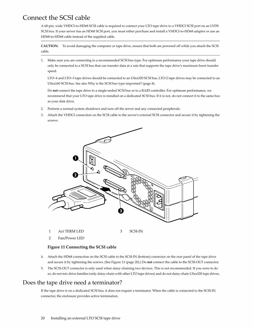
Connect the SCSI cableA 68-pin, wide VHDCI-to-HD68 SCSI cable is required to connect your LTO tape drive to a VHDCI SCSI port on an LVDSSCSI bus. If your server has an HD68 SCSI port, you must either purchase and install a VHDCI-to-HD68 adapter or use anHD68-to-HD68 cable instead of the supplied cable.
CAUTION: To avoid damaging the computer or tape drive, ensure that both are powered off while you attach the SCSIcable.
1. Make sure you are connecting to a recommended SCSI bus type. For optimum performance your tape drive shouldonly be connected to a SCSI bus that can transfer data at a rate that supports the tape drive's maximum burst transferspeed.
LTO–4 and LTO–3 tape drives should be connected to an Ultra320 SCSI bus, LTO-2 tape drives may be connected to anUltra160 SCSI bus. See also Why is the SCSI bus type important? (page 8).
Do not connect the tape drive to a single-ended SCSI bus or to a RAID controller. For optimum performance, werecommend that your LTO tape drive is installed on a dedicated SCSI bus. If it is not, do not connect it to the same busas your disk drive.
2. Perform a normal system shutdown and turn off the server and any connected peripherals.
3. Attach the VHDCI connection on the SCSI cable to the server's external SCSI connector and secure it by tightening thescrews.
SCSI-IN3Act TERM LED1
Fan/Power LED2
Figure 11 Connecting the SCSI cable
4. Attach the HD68 connection on the SCSI cable to the SCSI-IN (bottom) connector on the rear panel of the tape driveand secure it by tightening the screws. (See Figure 11 (page 20).) Do not connect the cable to the SCSI-OUT connector.
5. The SCSI-OUT connector is only used when daisy-chaining two devices. This is not recommended. If you were to doso, do not mix drive families (only daisy-chain with other LTO tape drives) and do not daisy-chain Ultra320 tape drives.
Does the tape drive need a terminator?If the tape drive is on a dedicated SCSI bus, it does not require a terminator. When the cable is connected to the SCSI-INconnector, the enclosure provides active termination.
20 Installing an external LTO SCSI tape drive
If it is not the only device on the SCSI bus, you must make sure that the SCSI bus is terminated. You can do this in two ways:
• Place the tape drive at the end of the chain and attach the HD68 connection on the SCSI cable to the SCSI-IN connector;the enclosure provides active termination.
• Attach the HD68 connection on the SCSI cable to the SCSI-IN connector and use the SCSI-OUT connector on the tapedrive to connect to the next device in the chain. Make sure that the last device in the chain is terminated with an LVDSmultimode terminator.
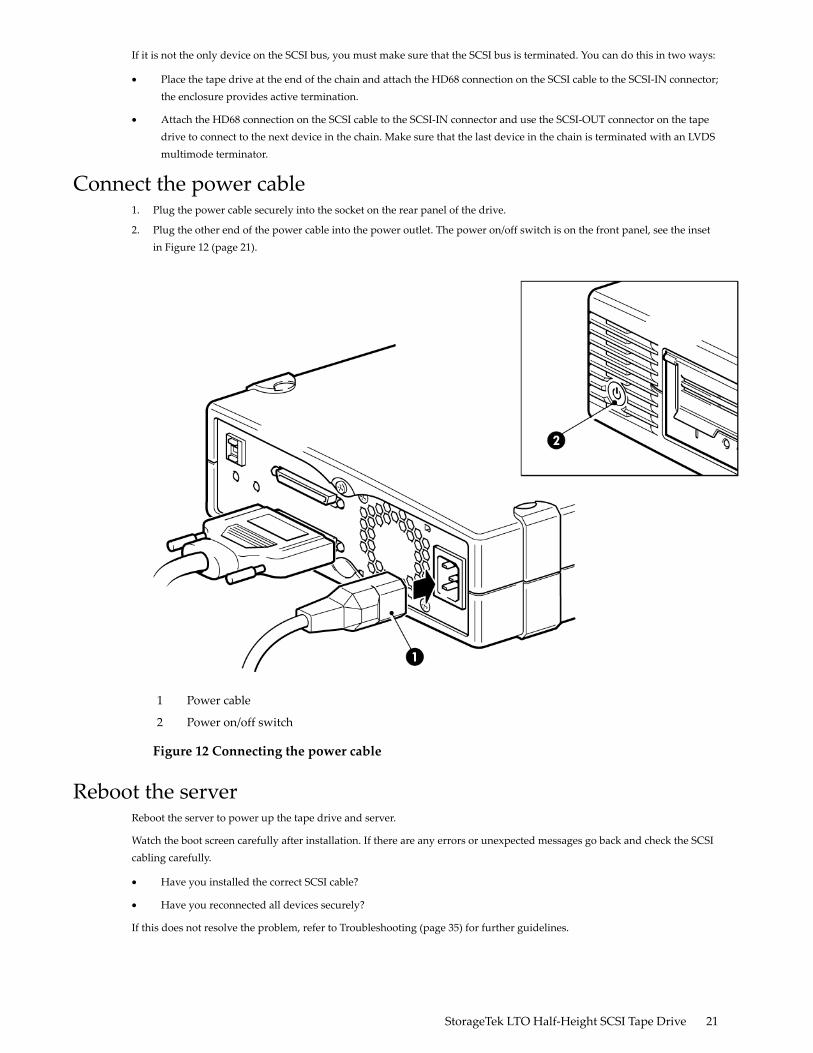
Connect the power cable1. Plug the power cable securely into the socket on the rear panel of the drive.
2. Plug the other end of the power cable into the power outlet. The power on/off switch is on the front panel, see the insetin Figure 12 (page 21).
Power cable1
Power on/off switch2
Figure 12 Connecting the power cable
Reboot the serverReboot the server to power up the tape drive and server.
Watch the boot screen carefully after installation. If there are any errors or unexpected messages go back and check the SCSIcabling carefully.
• Have you installed the correct SCSI cable?
• Have you reconnected all devices securely?
If this does not resolve the problem, refer to Troubleshooting (page 35) for further guidelines.
StorageTek LTO Half-Height SCSI Tape Drive 21

22
4 Verify installationOnce you have installed the drive hardware, check that drivers have been installed correctly and that you have the correctversion of backup software, and verify that the tape drive is functioning properly before you store your valuable data.
We recommend that you download the latest driver from the My Oracle Support (MOS) website (https://support.oracle.com).See also Solaris drivers (page 10).
NOTE: Certain backup applications require you to use their own tape driver instead of the Solaris tape driver.
1. Switch on the drive and the server.
2. The tape drive will run its hardware self-test, which takes about 5 seconds. If the self-test passes, the green Ready LEDflashes and then shows steady green. If the test fails, the Drive Error and Tape Error LEDs flash, while the Ready andClean LEDs are off. This continues until the drive is reset. See Understanding the LEDs (page 25) for more informationabout front panel lights.
3. Verify that the tape drive installation was successful.
4. For all operating systems ensure that you have downloaded any upgrades necessary for your backup application. Checkhttp://www.oracle.com for software compatibility and install any recommended upgrades.
5. Carry out a backup-and-restore test to check that the drive can write data to tape. Use a blank cartridge.
Native backup applications can be used to check basic tape drive operation, but they will not support all the advancedfeatures of your tape drive. We recommend that you upgrade your software application before running this test.
StorageTek LTO Half-Height SCSI Tape Drive 23

24

5 Understanding the LEDsIn this chapter:
• Your StorageTek LTO tape drive (page 25)
• Understanding LED sequences (page 25)
Your StorageTek LTO tape driveSee also Understanding LED sequences (page 25).
5. Drive LED1. Cartridge door
6. ReadyLED2. On/Off switch (external drives only)
7. Eject button3. Clean LED
4. Tape LED
Figure 13 Front view of StorageTek LTO-4 external tape drive
Understanding LED sequencesThe meaning of different patterns of LEDs is as follows:
Table 5 LED sequences
Action requiredCauseLED Sequence
Make sure the drive is switched on. The poweron/off switch on an external drive incorporatesa green LED.
Drive may not have power,may be faulty or may havebeen power-cycled or resetduring a firmware upgrade.
All LEDs OFF.Check the power cable connection and replacethe cable if necessary. On external drives, youcan use the power cable from your monitor oranother device to check that the connection isworking.If the power supply is present and all LEDsremain off, power-cycle or reset the drive. If itstill fails, call for service.
Power-cycle or reset the drive.The drive has failed to executepower-on self-test (POST). If the error condition reappears, call for service.
Ready and CleanOFF. Drive andTape FLASH.
None. This is normal.The drive is ready foroperation.
Ready is ON.
StorageTek LTO Half-Height SCSI Tape Drive 25
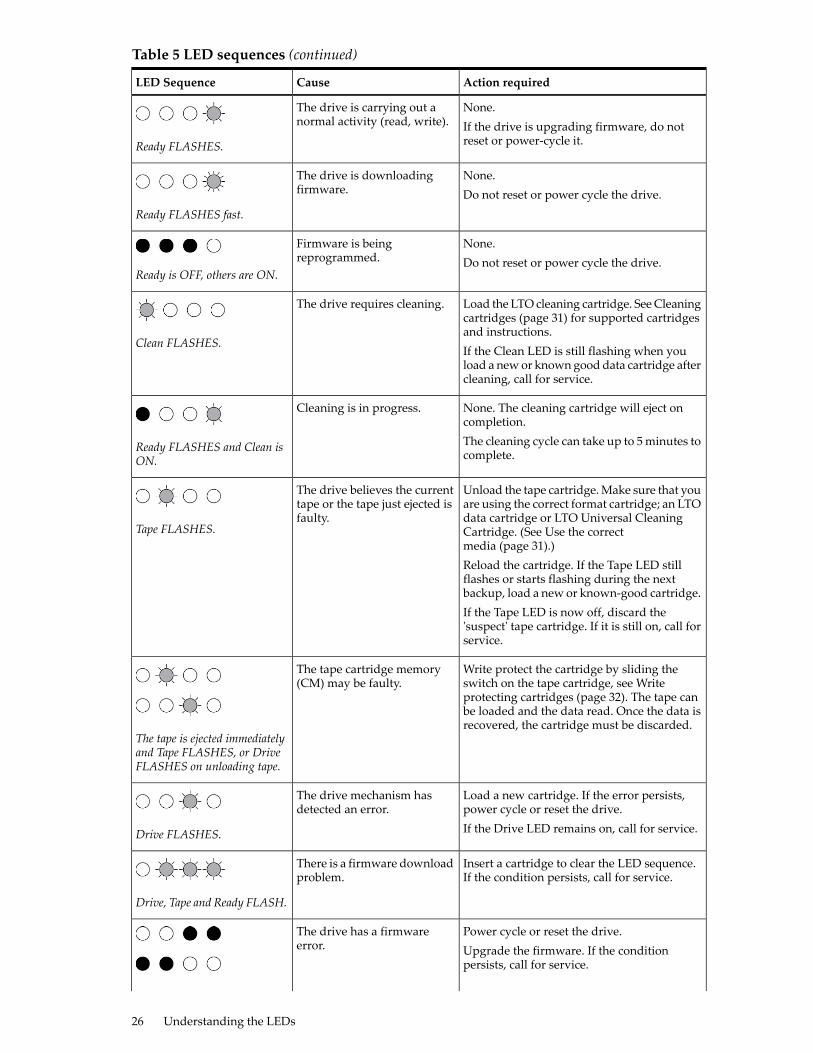
Table 5 LED sequences (continued)
Action requiredCauseLED Sequence
None.The drive is carrying out anormal activity (read, write). If the drive is upgrading firmware, do not
reset or power-cycle it.Ready FLASHES.
None.The drive is downloadingfirmware. Do not reset or power cycle the drive.
Ready FLASHES fast.
None.Firmware is beingreprogrammed. Do not reset or power cycle the drive.
Ready is OFF, others are ON.
Load the LTO cleaning cartridge. See Cleaningcartridges (page 31) for supported cartridgesand instructions.
The drive requires cleaning.
Clean FLASHES.If the Clean LED is still flashing when youload a new or known good data cartridge aftercleaning, call for service.
None. The cleaning cartridge will eject oncompletion.
Cleaning is in progress.
The cleaning cycle can take up to 5 minutes tocomplete.
Ready FLASHES and Clean isON.
Unload the tape cartridge. Make sure that youare using the correct format cartridge; an LTO
The drive believes the currenttape or the tape just ejected isfaulty.
Tape FLASHES.data cartridge or LTO Universal CleaningCartridge. (See Use the correctmedia (page 31).)Reload the cartridge. If the Tape LED stillflashes or starts flashing during the nextbackup, load a new or known-good cartridge.If the Tape LED is now off, discard the'suspect' tape cartridge. If it is still on, call forservice.
Write protect the cartridge by sliding theswitch on the tape cartridge, see Write
The tape cartridge memory(CM) may be faulty.
protecting cartridges (page 32). The tape canbe loaded and the data read. Once the data isrecovered, the cartridge must be discarded.
The tape is ejected immediatelyand Tape FLASHES, or DriveFLASHES on unloading tape.
Load a new cartridge. If the error persists,power cycle or reset the drive.
The drive mechanism hasdetected an error.
If the Drive LED remains on, call for service.Drive FLASHES.
Insert a cartridge to clear the LED sequence.If the condition persists, call for service.
There is a firmware downloadproblem.
Drive, Tape and Ready FLASH.
Power cycle or reset the drive.The drive has a firmwareerror. Upgrade the firmware. If the condition
persists, call for service.
26 Understanding the LEDs
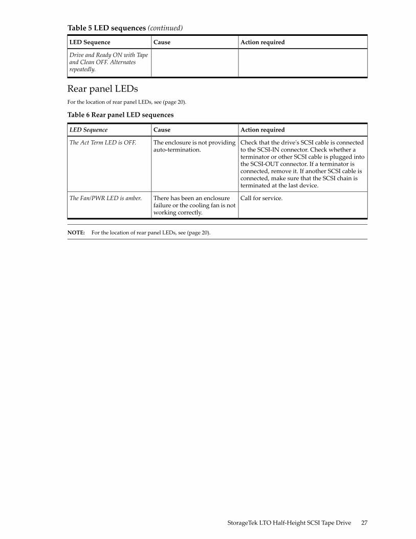
Table 5 LED sequences (continued)
Action requiredCauseLED Sequence
Drive and Ready ON with Tapeand Clean OFF. Alternatesrepeatedly.
Rear panel LEDsFor the location of rear panel LEDs, see (page 20).
Table 6 Rear panel LED sequences
Action requiredCauseLED Sequence
Check that the drive's SCSI cable is connectedto the SCSI-IN connector. Check whether a
The enclosure is not providingauto-termination.
The Act Term LED is OFF.
terminator or other SCSI cable is plugged intothe SCSI-OUT connector. If a terminator isconnected, remove it. If another SCSI cable isconnected, make sure that the SCSI chain isterminated at the last device.
Call for service.There has been an enclosurefailure or the cooling fan is notworking correctly.
The Fan/PWR LED is amber.
NOTE: For the location of rear panel LEDs, see (page 20).
StorageTek LTO Half-Height SCSI Tape Drive 27

28
6 Operating your tape driveIn this chapter:
• Loading a cartridge (page 29)
• Unloading a cartridge (page 29)
• Removing power from the drive (page 30)
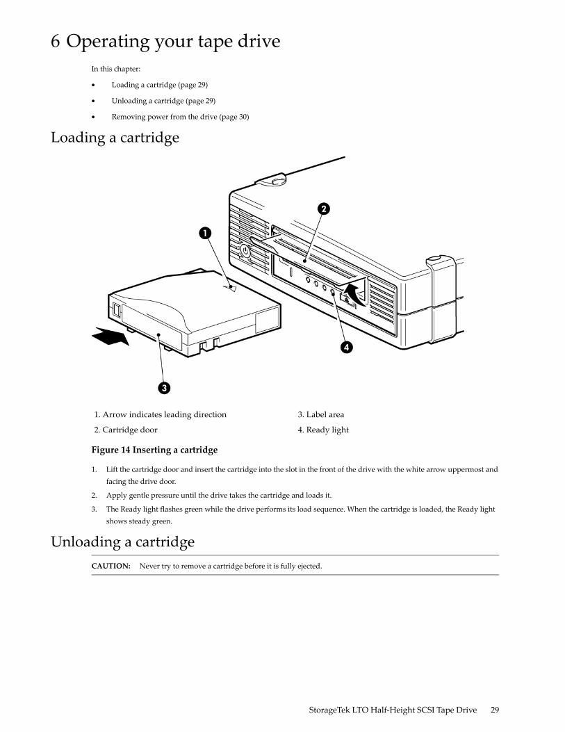
Loading a cartridge
3. Label area1. Arrow indicates leading direction
4. Ready light2. Cartridge door
Figure 14 Inserting a cartridge
1. Lift the cartridge door and insert the cartridge into the slot in the front of the drive with the white arrow uppermost andfacing the drive door.
2. Apply gentle pressure until the drive takes the cartridge and loads it.
3. The Ready light flashes green while the drive performs its load sequence. When the cartridge is loaded, the Ready lightshows steady green.
Unloading a cartridgeCAUTION: Never try to remove a cartridge before it is fully ejected.
StorageTek LTO Half-Height SCSI Tape Drive 29
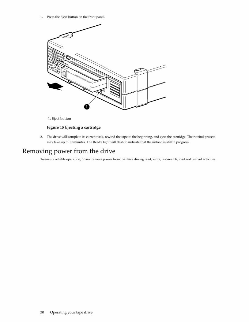
1. Press the Eject button on the front panel.
1. Eject button
Figure 15 Ejecting a cartridge
2. The drive will complete its current task, rewind the tape to the beginning, and eject the cartridge. The rewind processmay take up to 10 minutes. The Ready light will flash to indicate that the unload is still in progress.
Removing power from the driveTo ensure reliable operation, do not remove power from the drive during read, write, fast-search, load and unload activities.
30 Operating your tape drive
7 Use the correct mediaIn this chapter:
• Ordering media (page 31)
• Cartridges (page 31)
• WORM data cartridges (page 31)
• Write protecting cartridges (page 32)
• Cleaning the tape drive (page 32)
• Handling cartridges (page 33)
• Operating and storage environment (page 33)
Ordering mediaUse the Ultrium data and cleaning tape cartridges designed for your tape drive. To order data and cleaning cartridges pleaseuse the contact information below to locate the nearest tape media reseller.
In the US contact 1 877 STK Tape
Outside US contact [email protected]
CartridgesData cartridges
LTO tape drives use Ultrium tape cartridges. These are single-reel cartridges that match your drive's format and are optimizedfor high capacity, throughput and reliability. Compatible media can be recognized by the LTO logo, which is the same as thelogo on the front of your drive. Do not use other format cartridges in your tape drive and do not use Ultrium cartridges inother format tape drives.
For optimum performance always use a data cartridge that matches the specification of your tape drive. A lower specificationwill have a lower transfer speed and may not support write activities; a higher specification will not support read or write.
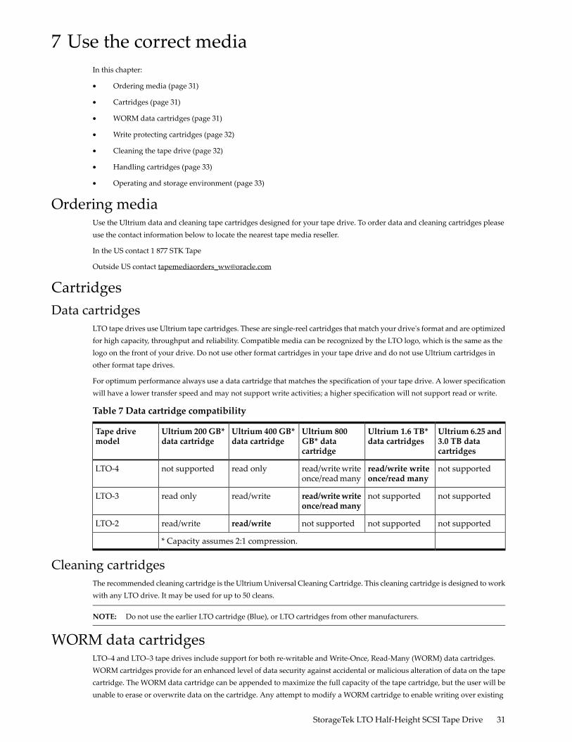
Table 7 Data cartridge compatibility
Ultrium 6.25 and3.0 TB datacartridges
Ultrium 1.6 TB*data cartridges
Ultrium 800GB* datacartridge
Ultrium 400 GB*data cartridge
Ultrium 200 GB*data cartridge
Tape drivemodel
not supportedread/write writeonce/read many
read/write writeonce/read many
read onlynot supportedLTO-4
not supportednot supportedread/writewriteonce/readmany
read/writeread onlyLTO-3
not supportednot supportednot supportedread/writeread/writeLTO-2
* Capacity assumes 2:1 compression.
Cleaning cartridgesThe recommended cleaning cartridge is the Ultrium Universal Cleaning Cartridge. This cleaning cartridge is designed to workwith any LTO drive. It may be used for up to 50 cleans.
NOTE: Do not use the earlier LTO cartridge (Blue), or LTO cartridges from other manufacturers.
WORM data cartridgesLTO–4 and LTO–3 tape drives include support for both re-writable and Write-Once, Read-Many (WORM) data cartridges.WORM cartridges provide for an enhanced level of data security against accidental or malicious alteration of data on the tapecartridge. The WORM data cartridge can be appended to maximize the full capacity of the tape cartridge, but the user will beunable to erase or overwrite data on the cartridge. Any attempt to modify a WORM cartridge to enable writing over existing
StorageTek LTO Half-Height SCSI Tape Drive 31
data will result in the media becoming permanently write protected. It should still be readable in a WORM drive, dependingupon the severity of the tampering, but no further appended backups will be possible.
WORM data cartridges are clearly identified by their distinctive, two-tone cartridge color. They can only be used with LTOtape drives that support the WORM feature.
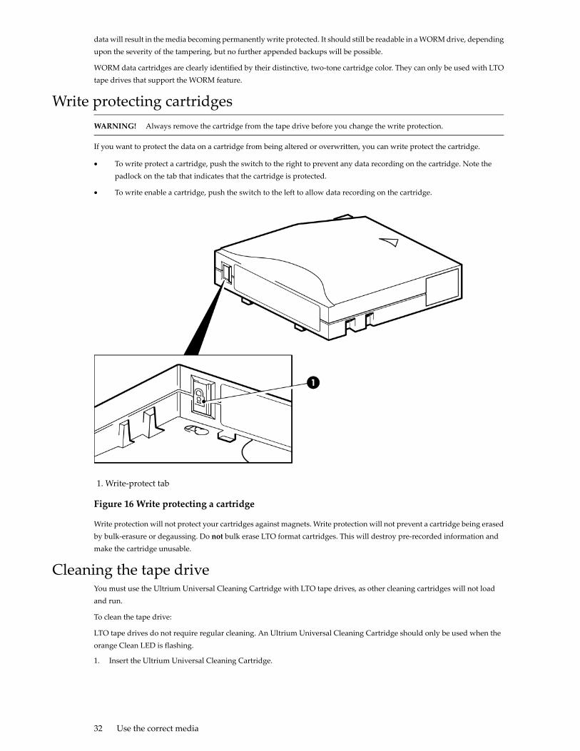
Write protecting cartridgesWARNING! Always remove the cartridge from the tape drive before you change the write protection.
If you want to protect the data on a cartridge from being altered or overwritten, you can write protect the cartridge.
• To write protect a cartridge, push the switch to the right to prevent any data recording on the cartridge. Note thepadlock on the tab that indicates that the cartridge is protected.
• To write enable a cartridge, push the switch to the left to allow data recording on the cartridge.
1. Write-protect tab
Figure 16 Write protecting a cartridge
Write protection will not protect your cartridges against magnets. Write protection will not prevent a cartridge being erasedby bulk-erasure or degaussing. Do not bulk erase LTO format cartridges. This will destroy pre-recorded information andmake the cartridge unusable.
Cleaning the tape driveYou must use the Ultrium Universal Cleaning Cartridge with LTO tape drives, as other cleaning cartridges will not loadand run.
To clean the tape drive:
LTO tape drives do not require regular cleaning. An Ultrium Universal Cleaning Cartridge should only be used when theorange Clean LED is flashing.
1. Insert the Ultrium Universal Cleaning Cartridge.
32 Use the correct media

2. The drive will carry out its cleaning cycle and eject the cartridge on completion (which can take up to 5 minutes). Duringthe cleaning cycle the orange Clean LED will be on solid and the green Ready LED will flash.
Each Ultrium Universal Cleaning Cartridge cleaning cartridge can be used up to 50 times with LTO tape drives. If thecleaning cartridge is ejected immediately with the Tape LED on, it has expired.
Handling cartridges• Do not touch the tape media.
• Do not attempt to clean the tape path or tape guides inside the cartridge.
• Do not leave cartridges in the drive. The tape loses tension in the power-off state, which can lead to problems, particularlyif the drive has been moved.
• Do not leave cartridges in excessively dry or humid conditions.
• Do not leave cartridges in direct sunlight or in places where magnetic fields are present (for example, under telephones,next to monitors or near transformers).
• Do not drop cartridges or handle them roughly.
• Stick labels onto the label area only.
• Do not bulk erase (or degauss) LTO format cartridges because this will render them unusable.
Operating and storage environmentTo prevent condensation and for long life, the cartridge should only be operated or stored as follows:
• Operation: 100° C to 45° C (50° F to 113° F)
• Day-to-day storage (in plastic container): 16° C to 32° C (60° F to 90° F)
• Non-condensing relative humidity: 10% to 80% (operating), 20% to 60% (non-operating)
Tapes intended for long-term storage should be stored in the plastic containers, at temperatures between 5° C and 25° C (41°F and 75° F) and 20% to 60% relative humidity.
StorageTek LTO Half-Height SCSI Tape Drive 33

34
8 TroubleshootingIn this chapter:
• General Procedure (page 35)
• Optimizing performance (page 36)
• Problems with cartridges (page 37)
General procedureIf a problem occurs, the first step is to try to establish whether the problem lies with the cartridge, the drive, the host computerand connections, or the way the system is being operated.
Has the system just been installed?
There could be an installation problem:
1. Check through the information in the relevant installation chapter of this guide.
2. Check the power connectors and SCSI cabling.
3. Is the SCSI ID correctly set? Is there a SCSI system conflict? Has the SCSI bus been correctly terminated? See Check theinternal drive's SCSI ID (page 11) andCheck the external drive's SCSI ID (page 19).
4. Are appropriate drivers and application software installed on the host?
5. Check the environmental conditions against the specified limits.
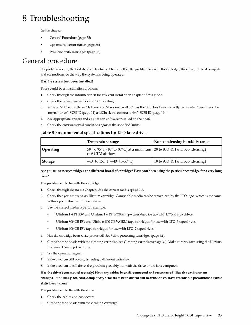
Table 8 Environmental specifications for LTO tape drives
Non-condensing humidity rangeTemperature range
20 to 80% RH (non-condensing)50° to 95° F (10° to 40° C) at a minimumof 6 CFM airflow
Operating
10 to 95% RH (non-condensing)–40° to 151° F (–40° to 66° C)Storage
Are you using new cartridges or a different brand of cartridge? Have you been using the particular cartridge for a very longtime?
The problem could lie with the cartridge:
1. Check through the media chapter, Use the correct media (page 31).
2. Check that you are using an Ultrium cartridge. Compatible media can be recognized by the LTO logo, which is the sameas the logo on the front of your drive.
3. Use the correct media type, for example:
• Ultrium 1.6 TB RW and Ultrium 1.6 TB WORM tape cartridges for use with LTO–4 tape drives.
• Ultrium 800 GB RW and Ultrium 800 GB WORM tape cartridges for use with LTO–3 tape drives.
• Ultrium 400 GB RW tape cartridges for use with LTO–2 tape drives.
4. Has the cartridge been write protected? See Write protecting cartridges (page 32).
5. Clean the tape heads with the cleaning cartridge, see Cleaning cartridges (page 31). Make sure you are using the UltriumUniversal Cleaning Cartridge.
6. Try the operation again.
7. If the problem still occurs, try using a different cartridge.
8. If the problem is still there, the problem probably lies with the drive or the host computer.
Has the drive been moved recently? Have any cables been disconnected and reconnected? Has the environmentchanged—unusually hot, cold, dampor dry?Has there been dust or dirt near the drive.Have reasonable precautions againststatic been taken?
The problem could lie with the drive:
1. Check the cables and connectors.
2. Clean the tape heads with the cleaning cartridge.
StorageTek LTO Half-Height SCSI Tape Drive 35
3. If the problem persists, check the environmental conditions against the specified limits, see (page 35). Perhaps movethe drive to a more suitable site.
Has a new operating system been installed in the host computer? Has new backup software been installed?
The problem could lie with the host or the software. Consult the computer's operating manuals, the software manual, orseek help from a service engineer.
Optimizing performanceVarious factors can affect tape drive performance, particularly in a network environment. In nearly all cases when performanceis not as expected, it is the data rates of the disk subsystem that cause the bottleneck.
If your tape drive is not performing as well as expected—for example, if backup windows are longer than expected—pleaseconsider the following points before contacting Customer Support.
Is the tape drive on a dedicated SCSI bus?We recommend that the tape drive is the only device on the SCSI bus. If it is not, ensure that other devices are LVDS compliant.If they are single-ended, the bus will switch to single–ended mode with a lower transfer speed. There will also be restrictionson cable length.
Can your system deliver the required performance?• The LTO–4 tape drive can write uncompressed data at up to 80 MB/s (288 GB/hour).
• The LTO–3 tape drive can write uncompressed data at up to 60 MB/s (216 GB/hour).
• The LTO–2 tape drive can write uncompressed data at up to 24 MB/s (86 GB/hour).
To obtain this performance it is essential that your whole system can deliver this performance. In most cases, the backupapplication will provide details of the average time taken at the end of the backup.
Typical areas where bottlenecks can occur are:
• Disk subsystem
A single-spindle disk will not be able to deliver good data throughput at poor compression ratios. Best practice toensure good throughput is to utilize multiple disk spindles or data sources.
A single-spindle disk may be sufficient for an LTO-2 tape drive, depending on your data's compressibility. Best practiceto ensure good throughput is to utilize multiple disk spindles or data sources.
• System architecture
Be aware of the architecture of your data protection environment.
The aggregation of multiple client sources over a network provides a good way of delivering good performance, butanything less than Gigabit Ethernet will limit performance for LTO tape drives.
Some enterprise class backup applications can be made to interleave data from multiple sources, such as clients ordisks, to keep the tape drive working at optimum performance.
• Tape media type
The data cartridge should match the specification of the tape drive. A lower specification will have a lower transferspeed (see Data cartridges (page 31)). Use:
◦ Ultrium 1.6 TB R/W or Ultrium 1.6 TB WORM cartridges with LTO–4 tape drives
◦ Ultrium 800 GB R/W or Ultrium 800 GB WORM cartridges with LTO–3 tape drives
◦ Ultrium 400 GB R/W cartridges with LTO–2 tape drives
• Data and file types
The type of data being backed up or restored can affect performance. Typically, small files incur greater overhead inprocessing and access than large files. Equally, data that is not compressible will always limit the speed at which thedrive can write/read data. You will achieve no more than native rates with uncompressible data.
36 Troubleshooting

Examples of files that compress well are plain text files, spreadsheets; those that compress poorly are either compressedas part of their format (such as, JPEG photographic files) or stored as compressed (such as, .ZIP files or .gz/.Z files onUnix platforms).
Problems with cartridgesIf you experience any problems using LTO branded cartridges, check:
• The cartridge case is intact and that it contains no splits, cracks or damage.
• The cartridge has been stored at the correct temperature and humidity. This prevents condensation. See the insert includedwith the tape cartridge for storage conditions.
• The write-protect switch is fully operational. It should move from side to side with a positive click.
The cartridge is jammedIf the cartridge is jammed or the backup application is unable to eject it, you can force eject the cartridge. If the failure occursregularly, contact Customer Support.
1. Either press and hold the Eject button on the front of the tape drive for at least 10 seconds.
2. Wait for the cartridge to be ejected. This process may take up to 10 minutes (the maximum rewind time). It is importantthat you allow sufficient time for the drive to complete this process. If you interrupt it, you may damage the media or thetape drive. The drive is then reset as though you had turned the power off and then on again.
You may lose data if you force eject a cartridge. The tape may also become unreadable because an EOD (End of Data)mark may not be properly written.
3. If the cartridge is still jammed, the tape drive has failed, contact Customer Support.
The drive will not accept the cartridge (or ejects it immediately)The cartridge may have been damaged, for example dropped, or the drive may have a fault. If it is a cleaning cartridge, it hasprobably expired and should be discarded immediately. For data cartridges:
1. Check that the drive has power (the power cable is properly connected and the Ready LED is on).
2. Check that you are using the correct media. Use only Ultrium media, (see Use the correct media (page 31)).
• Ultrium 1.6 TB RW and Ultrium 1.6 TB WORM tape cartridges for use with LTO–4 tape drives.
• Ultrium 800 GB RW and Ultrium 800 GB WORM tape cartridges for use with LTO–3 tape drives.
• Ultrium 400 GB RW tape cartridges for use with LTO–2 tape drives.
3. Make sure that you have loaded the cartridge with the correct orientation (see Loading a cartridge (page 29)).
4. Check for damage to your media and discard it if it is damaged.
5. Use a new or known-good piece of media and see if it loads. If it does, the original cartridge is faulty and should bediscarded.
6. Check if another LTO drive of the same model will accept the cartridge. If it does, the original drive may be faulty. Beforecalling customer service, please check that the tape drive is responding.
StorageTek LTO Half-Height SCSI Tape Drive 37

38

A SCSI configuration guideIn this appendix:• SCSI in Ultrium devices (page 39)• SCSI terminology (page 39)• Setting up the SCSI bus (page 39)• Identifying SCSI IDs (page 40)• Setting the SCSI ID on HP StorageWorks Ultrium drives (page 40)• SCSI termination (page 40)• SCSI cables (page 42)
SCSI in LTO devicesLTO-4 and LTO-3 tape drives are high performance Ultra320 SCSI compatible devices; LTO-2 tape drives are high performanceUltra160 SCSI compatible devices.They are designed to operate on a low voltage differential (LVDS) SCSI interface and are not compatible with high voltagedifferential (HVD) SCSI devices.LTO-4 and LTO-3 tape drives support a burst transfer rate of 320 MB/sec; LTO-2 tape drives support a burst transfer rate of160 MB/sec.To benefit from this level of performance, it is important to ensure that the drives are connected to a SCSI bus of a similar orhigher specification. This means that you need:
• An Ultra320 bus for LTO-4 and LTO-3 tape drives. An Ultra160 or Ultra320 bus for LTO-2 tape drives.If you attach the drive to a lower specification SCSI bus, it will still work but data transfer may not be as quick. Ultra2SCSI is also supported, but performance may be degraded.
• LVDS-rated SCSI cabling and terminators.The LVDS interface enables the data to be transferred at the drive's maximumrate and provides a maximum cable length of 12 meters.
Daisy chaining devicesNOTE: We do not recommend daisy chaining the LTO-4 or LTO-3 tape drive with other devices.
If you need to connect multiple devices to the bus, performance may be restricted if there are too many devices on the bus thatare accessed simultaneously. Connecting devices of lower SCSI specification, such as Ultra2 or Ultra SCSI, may also restrictperformance to your tape drive. Using Single Ended 8-Bit SCSI devices on the same bus is not recommended, as performancewill be severely impacted and complicated bus configuration is required to overcome bus termination issues.Make sure that the last device on the SCSI bus is terminated. We recommend that you do not attach the tape drive to the sameSCSI bus as the disk drive. See SCSI termination (page 40) for more information about terminating LTO tape drives.
SCSI terminologySCSI is a bus interface: all the devices are connected to a single cable (some of this may be inside and some outside the hostcomputer's case). The connection to the host itself is known as the Host Bus Adapter (HBA). You can have several HBAs in asingle computer, each with its own SCSI bus: this is a common arrangement in high-performance servers. Some host busadapters have more than one SCSI bus available on a single card.Various terms are used when describing SCSI devices. These terms relate to factors that affect performance and cable length:
• The speed of the data bus, which may be Fast, Ultra, Ultra2, Ultra3, Ultra160 or Ultra320.• The width of the data bus, which may be Wide or Narrow (16-Bit or 8-Bit).• The voltage level of the interface, which may be single-ended (SE) or low voltage differential SCSI (LVDS).
Setting up the SCSI busEach device on a SCSI bus, including the SCSI host bus adapter (HBA), must be configured with a unique ID (identifier). TheSCSI bus must be terminated.
NOTE: We recommend that a dedicated host bus adapter is used for the tape drive.
SCSI ID numbersFor wide SCSI buses, the SCSI ID will be a number from 0 through 15, so a typical wide SCSI HBA can accommodate up to 15other devices. (On narrow SCSI buses, the SCSI ID is a number from 0 through 7.)
StorageTek LTO Half-Height SCSI Tape Drive 39
Each device must have a unique SCSI ID. The drive can be assigned any unused ID between 0 and 15. Do not use SCSI ID7, which is reserved for the SCSI controller. SCSI ID 0 is typically assigned to the boot disk and should also not be usedunless the tape drive is on a dedicated SCSI bus.SCSI ID 7 is normally reserved for the HBA because it has the highest priority on the bus. On wide buses, the priority runsfrom 7 (highest) to 0, then 15 down to 8 (lowest).
NOTE: As a general rule, avoid putting tape devices on the same bus as any hard disks.
Identifying SCSI IDsIf your computer already has devices connected to the SCSI bus, you will need to know their IDs to avoid any conflict withthe new tape drive. Here are some methods of finding out the information:
• Most computers display a list of SCSI devices and IDs during the boot-up process. This usually scrolls past very fast.If you press the [Pause] key, you should be able to halt the scrolling and view the list.
• On Windows systems, you can use the Device Manager.• If you have Novell NetWare installed, use its LIST DEVICES command.If none of these is available to you, try the following sources of information:
• The details of all installed devices and settings may have been written down and stored with your computer'sdocumentation (for new computers, this is often done by the supplier).
• Your HBA's documentation should tell you which settings it uses.• Look at each device to find out its ID. This is usually easy with external devices. With internal devices, you will
probably need the device's documentation to identify the SCSI ID setting, which is usually set with jumpers.
Setting the SCSI ID on LTO drivesNote that host adapters check SCSI IDs only at power-on, so any changes will not take effect until the host system ispower-cycled.
• On internal LTO tape drives, set the SCSI ID by attaching or removing jumpers at the rear of the drive, see Check theinternal drive's SCSI ID (page 11).
• On external LTO tape drives, the ID is displayed on the rear panel and can be set by pressing the little buttons aboveand below the number (using a ball point pen), see Check the external drive's SCSI ID (page 19).
SCSI terminationTerminators are essential, as they provide the correct voltages on the SCSI bus and prevent unwanted signal reflections frominterfering with data transfers. The rule is:
NOTE: There must be termination at both physical ends of the bus and only at the ends.
There are two main types of termination, active and passive. Active terminators reduce interference and allow faster datathroughput. On devices with high transfer speeds, such as LTO devices, active termination is required, using an LVDS ormultimode active terminator. (Multimode terminators allow both LVDS and single-ended devices to be connected to thesame bus. They detect the type of bus and automatically supply the correct termination.)Normally the HBA forms one end of the SCSI bus and provides termination. You only need to ensure that the other end ofthe bus is terminated.
Internal drivesLTO internal tape drives do not supply termination. A suitably terminated LVDS internal ribbon cable is supplied with thetape drive. The terminator is usually a small, rectangular block of plastic attached to the cable end and marked ‘SCSITerminator'.
40 SCSI configuration guide

Figure 17 SCSI termination in internal drives
As long as this terminator is attached, you do not need to take any further action. However, if you have other devices attachedto the cable, make sure that they have termination removed or disabled.
NOTE: If you have an internal and external device attached to the same SCSI bus, the HBA will be in the middle of the cableand thus its termination must be disabled. See the host bus adapter's documentation for details of how to do this.
External drivesFor LTO external tape drives the enclosure provides active termination.As long as the drive is the only device on the SCSI chain, no terminators are required. The green ACT Term LED on the rearof the drive indicates whether auto-termination is active (on) or not (off).Make sure the terminator is firmly attached to the SCSI-OUT connector on the rear of the device when you install it.
Figure 18 SCSI termination on a single LTO tape drive
If you have more than one device on the SCSI bus, daisy-chain them by connecting an LVDS-rated cable from the SCSI-OUTconnector on the first device to the SCSI-IN connector on the second device. Assuming you have two LTO tape drives connected,the enclosure on the second drive provides termination. The green ACT Term LED on the rear of the first drive will be off
StorageTek LTO Half-Height SCSI Tape Drive 41

while on the rear of the second drive it will be on. If the second device is not an LTO external drive, make sure that it isterminated using an LVDS-rated multimode terminator.
Figure 19 SCSI termination in daisy-chained external drives
SCSI cablesCables matter in SCSI systems. There are two factors to consider: cable length and cable quality.
Cable length• For LVDS SCSI the maximum length for a single device is 25 meters. For multiple devices, the maximum combined
internal/external length is 12 meters.• If you have a combination of LVDS and SE devices on the bus, the maximum cable length reverts to the SE specification.
This is 3 meters for four or fewer devices, and 1.5 meters for more than four devices. See also Note on SE and LVDinterfaces (page 43).
• For best performance, keep lengths to a minimum, but avoid very short overall lengths (less than 0.5 meters).
Cable quality• It is important to use good quality cables. Generally speaking, cable quality affects performance and reliability. This
is particularly true for external, shielded cables.• Look after your SCSI cables. In particular, take care when connecting or disconnecting not to damage the high-density
connectors. Avoid putting excessive twists in external shielded cables, as this can cause premature failure.
With internal devicesLTO tape drives have a 68-pin wide, high-density SCSI connector. A suitable cable with the correct termination is suppliedwith the tape drive. If you are using an LTO drive on an internal bus with other peripherals that run at Ultra2 speeds, it isimportant that a 68-pin LVDS-compatible ribbon cable is used. Do not connect your tape drive to lower-rated SCSI or tonarrow SCSI.
With external devicesYour tape drive requires a 68-pin VHDCI-to-HD68 SCSI cable to connect to the host server.
42 SCSI configuration guide

Note on SE and LVDS interfacesSE and LVDS define how the signals are transmitted along the cable.
• With single-ended (SE) SCSI, each signal travels over a single wire and each signal's value is determined by comparingthe signal to a paired ground wire. Signal quality tends to decrease over longer cable lengths or at increased signal speed.
• With low voltage differential (LVDS) signaling, signals travel along two wires and the difference in voltage between thewire pairs determines the signal value. This enables faster data rates and longer cabling with less susceptibility to noisethan SE signaling and reduced power consumption.
If you use LVDS SCSI devices on the same bus as single-ended devices this will switch the LVDS SCSI host adapter intosingle-ended mode and restrict cable length.If you connect only LVDS SCSI devices, the bus will operate in low voltage differential mode and Ultra160 and higher speedswill be enabled. If you use a combination of Ultra160 and Ultra2 devices, each device will operate at its optimum speed.
StorageTek LTO Half-Height SCSI Tape Drive 43

44

Index
Aaudience, 5
Bbackup software
drivers, 10supported, 10
backup software problems, 36buttons
Unload, 30
Ccabling
external drive, 20cartridge compatibility, 31cartridges
ejected, 37inserting, 29jammed, 37problems, 35, 37removing, 30
changing SCSI IDexternal drive, 19internal drive, 11
cleaning tape drive, 32compatibility
backup software, 10connecting cables
internal drive, 14conventions
document, 5text symbols, 5
Ddaisy chaining, 39default SCSI ID, 11, 19document
conventions, 5drive
operating, 29drive installation, 13drivers, 10
backup software, 10installing, 10
Eejected cartridge, 37external drive
cabling, 20
Ffront panel
drives, 25, 29
Hhandling media, 33
helpobtaining, 5
hostproblems, 36
Iinserting cartridges, 29installation
cables, 14changing SCSI ID, 11, 19external drive, 19internal drive, 13mounting bay, 12mounting hardware, 12problems, 35verifying, 23
installingdrivers, 10
Jjammed cartridge, 37
LLEDs, 25
Mmedia
cartridge compatibility, 31cleaning, 31, 32data, 31environment, 33handling, 33where to order, 31WORM, 31write protect, 32
mounting bay, 12mounting hardware, 12
Ooperating and storage environment, 33operating systems, 7operation
drives, 29optimizing performance, 36
Pperformance, 36power specification, 9, 14
SSCSI
cables, 42configuration guide, 39daisy chaining, 39terminology, 39
SCSI bus, 39SCSI bus types, 8
StorageTek LTO Half-Height SCSI Tape Drive 45

SCSI cable, 20SCSI cables, 14SCSI ID
default, 11, 19SCSI IDs, 40SCSI termination
external drive, 20, 41internal drive, 15, 40
supported models, 7symbols in text, 5
Ttape drive
front panel, 25LEDs, 25problems, 35
technical supportservice locator website, 6
text symbols, 5transfer rates, 7troubleshooting
after installation, 35drive, 35media, 35, 37
UUnload button, 30usage models, 9
Vverify installation, 23
WWORM cartridge, 31write protect, 32
46 Index