storm water control operation and maintenance plan · 5/13/2014 · storm water control operation...
TRANSCRIPT
STORM WATER CONTROL OPERATION AND MAINTENANCE PLAN
FOR
HAYSTACK LANDING ASPHALT FACILITY
3355 Petaluma Blvd. South
Sonoma, California
Prepared For: Dutra Group
2350 Kerner Blvd. Suite 200 San Rafael, CA 94901
Prepared By: CSW/Stuber-Stroeh Engineering Group, Inc.
45 Leveroni Court Novato, California 94949
(415)!883!9850
Prepared: May 13, 2014
CSW|ST2 File No.: 5.913.02

Storm Water Control Operations & Maintenance Plan Haystack Asphalt Facility May 13, 2014
P:\05\591302\General\Reports\Storm Water Control Operation & Maintenance Plan\2014!05!13 Haystack_O&M_Plan.docx Page i
TABLE OF CONTENTS
1. Summary of Storm Water Treatment Facilities ............................................................................... 1
1.1 Functions of Sand Filter Area
1.2 Sand Filter Area – Inspection/ Maintenance Considerations
1.3 Functions of Mechanical Treatment
1.4 Mechanical Treatment – Inspection/ Maintenance Considerations
1.5 Functions of Emergency Shut Off System
1.6 Emergency Shut Off System! Inspection/ Maintenance Considerations
2. Responsibility for Maintenance .......................................................................................................... 2 3. Summary of Drainage Areas ............................................................................................................... 3 4. General Maintenance Requirements.................................................................................................. 3 5. Calculations and Documentation ....................................................................................................... 5 6. Inspection and Maintenance Schedule .............................................................................................. 6 7. Reporting and Updates for Private Stormwater Facilities .............................................................. 6 8. Spill Observation and Clean Up......................................................................................................... 6 9. Certification ........................................................................................................................................... 7 10. Appendices
10.1 Inspection and Maintenance Log (Compile in this Section)
10.2 Updates and Revisions (Compile in this Section)
10.3 Inspection and Maintenance Checklist – Sand Filter Area
10.4 FloGard Perk Filter Systems – Cut Sheet
10.5 Inspection and Maintenance Checklist – FloGard Perk Filter Systems
10.6 Source and Treatment Control Operation and Maintenance
Inspection Annual Report
10.7 Storm Water Control Plan
10.8 Owner’s Certification

Storm Water Control Operations & Maintenance Plan Haystack Landing Asphalt Facility May 13, 2014
P:\05\591302\General\Reports\Storm Water Control Operation & Maintenance Plan\2014!05!13 Haystack_O&M_Plan.docx Page 1
1. SUMMARY OF STORM WATER TREATMENT FACILITIES
The Haystack Landing Asphalt Facility is a 35!acre project that includes an asphalt production facility, aggregate and sand stockpiles, conveyor belt, fire training station, and a habitat restoration area. The project is located at 3355 Petaluma Boulevard South in Sonoma County, just south of Petaluma. The site is bounded on the west by Highway 101, on the east by private property and the Petaluma River, and on the north and south by private property. Stormwater runoff from the hillside to the north, the fire training station, the asphalt area, and the temporary storage area is treated through the use of Sand Filter facilities with the alternative of additional Mechanical Treatment facilities. If the sand filters are found to be insufficient in removing contaminants from runoff then the Dutra Group (owner) will install mechanical treatment in addition to the sand filters to capture residual contaminants. If necessary, the alternative Mechanical Treatment structures will be Kristar FloGard Perk Filter. All stormwater treatment facilities for this project are sized based on criteria set forth in the Guidelines for the Standard Urban Storm Water Mitigation Plan, Storm Water Best Management Practices for New Development and Redevelopment, and per the Conditions of Approval, PLP04!0046 dated December 14, 2010. All drainage into and out of the treatment facilities is gravity fed. 1.1 Functions of Sand Filter Area
The Sand Filter area functions as a sand based filtration device that removes pollutants through a variety of physical, biological, and chemical treatment processes. The Sand Filter area consists of a sand mix, subdrain system, an alternative media filter vault, and a discharge pipe. Runoff velocities are reduced by being distributed evenly along a ponding area and interacting with the sand filter as it passes through to the storage layer. Exfiltration of the stored water from the Sand Filter area storage layer into the under drain system occurs over a period of days (after significant storm events). The water is subsequently conveyed into the drainage ditches, the Habitat Restoration area, and eventually into the Petaluma River
1.2 Sand Filter Area – Inspection/ Maintenance Considerations
The Sand Filter area requires frequent maintenance including measures to ensure that the area is functioning properly. Maintenance tasks can be completed by a qualified landscaping contractor. See the Inspection and Maintenance Checklist ! Sand Filter in the appendices for information regarding how to care for the Sand Filter area. Normal function of the Sand Filter area may include retaining water for up to 72 hours after a storm event, and will be sized to treat the 100!year storm volume

Storm Water Control Operations & Maintenance Plan Haystack Landing Asphalt Facility May 13, 2014
P:\05\591302\General\Reports\Storm Water Control Operation & Maintenance Plan\2014!05!13 Haystack_O&M_Plan.docx Page 2
1.3 Functions of Mechanical Treatment
Filtration devices such as the Kristar FloGard Perk Filters are designed to reduce pollutant loading by capturing sediments, oils, and metals close to the source and reduces the discharge load. The Mechanical Treatment will be used in conjunction with the sand filter treatment if residual contaminants are found to still be in the water after it has passed through the sand filter. The FloGard Perk Filter captures fine pollutant particles that are retained in the filter cartridges as the water flows through the media to an interior perforated pipe, dropping the treated stormwater into an outlet chamber which is then directed towards the outfall area.
1.4 Mechanical Treatment – Inspection/ Maintenance Considerations
The FloGard Perk Filter system requires periodic maintenance, including measures to ensure that the area is functioning properly, as well as removal of accumulated sediment, litter, and other floatables with three Levels of Service that can be found in section 4.2. See the Inspection and Maintenance Checklist – FloGard Perk Filter in Appendix 10.5 for information regarding how to care for the facilities.
1.5 Functions of Emergency Shut Off System The emergency shut off system is a valve placed between the sand filter system and the
mechanical system or discharge area and will allow the plant operator to stop discharge from the sand filter system to the drainage channels. A procedure for shutting off the system will be part of the routine training and included in the Industrial Storm Water Pollution & Prevention Plan (ISWPPP).
1.6 Emergency Shut Off System! Inspection/ Maintenance Considerations The emergency shut off system will be inspected on a bi!yearly basis to insure that the valve
is in operating condition. Maintenance tasks can be completed by the plant operator or a qualified landscaping contractor that is familiar with the sand and media filter systems.
2. RESPONSIBILITY FOR MAINTENANCE
The property owner (Dutra Group) and any future owner is responsible for maintaining the private drainage system including rain gutters, downspouts, area drains, risers, inlets, outlets, overflows, clean!outs, pipelines, and connectors that direct water to the stormwater treatment facilities. Any major maintenance (such as replacing sand, re!grading, subdrain replacement, or similar effort) of the Sand Filter areas should only be conducted by a competent professional such as a licensed landscape contractor.
Storm Water Control Operations & Maintenance Plan Haystack Landing Asphalt Facility May 13, 2014
P:\05\591302\General\Reports\Storm Water Control Operation & Maintenance Plan\2014!05!13 Haystack_O&M_Plan.docx Page 3
Landscape contractors retained for maintenance must familiarize themselves with the purposes, design specifications, features, and mode of operation of the treatment facilities. Maintenance service providers (landscape maintenance and other maintenance), including maintenance supervisors and employees, need to be informed of the specific maintenance requirements for the treatment facilities and should review the Storm Water Control Operations and Maintenance Plan (this document).
3. SUMMARY OF DRAINAGE AREAS
The project is divided into five (5) drainage management areas (DMAs) identified as 1!5. DMAs 1 and 3 discharge into the proposed sand filter at the northeast corner of the asphalt plant which then discharges into WJ. DMA 2 discharges into the proposed sand filter located on the western side of the asphalt plant next to the haul route from the silos, and is discharged into DD6. A portion of DMA 3 and all of DMA 4 flows to the southeast portion of the asphalt plant area next to DD1 and discharges into DD1. DMA 5 flows southwest in the Temporary Storage Area to a sand filter that discharges into DD2. The stormwater treatment facilities utilized at this site include Sand Filter areas with an alternative to use Mechanical treatment if necessary. Treatment facility locations are located on the Storm Water Control Plan, see Appendix 10.7.
4. GENERAL MAINTENANCE REQUIREMENTS
Landscape contractors retained for maintenance must familiarize themselves with the purposes, design specifications, features, and mode of operation of the treatment facilities and should review the Storm Water Control Plan (in addition to this document). As will be reflected in contracts for landscape maintenance and other maintenance services, maintenance supervisors and employees need to be informed of the following specific maintenance requirements for the treatment facilities. Maintenance instructions include the following (see Inspection and Maintenance Checklist for more detailed maintenance instructions).
Summary of Maintenance Requirements
The stormwater facilities proposed throughout the project site to meet runoff quality requirements include sand filter facilities and mechanical treatment facilities. The following are minimum maintenance requirements for these types of facilities.
4.1 Sand Filter Areas
These facilities remove pollutants primarily by filtering runoff slowly through an active layer of sand. Routine maintenance is needed to ensure flow is unobstructed, erosion is prevented, and the sand is filtering the stormwater thoroughly. Typical maintenance consists of the following:

Storm Water Control Operations & Maintenance Plan Haystack Landing Asphalt Facility May 13, 2014
P:\05\591302\General\Reports\Storm Water Control Operation & Maintenance Plan\2014!05!13 Haystack_O&M_Plan.docx Page 4
! Inspect sand filters after every major storm in the first few months after
construction to ensure that the system is functioning properly.
! Inspect facility once during the wet season after a large rain event to determine whether the facility is draining completely within 72 hours.
! Ensure that flow is not bypassing the sand filter system.
! Inspect inlets for channels, exposure of sand, or other evidence of erosion. Clear any obstructions and remove any accumulation of sediment. Examine rock or other material used as a splash pad and replenish if necessary.
! Inspect outlets for erosion or plugging.
! Inspect side slopes for evidence of instability or erosion and correct as necessary.
! Remove and replace top 2 inches of sand if facility drain time exceeds 72 hours.
! Remove accumulated sediment every year or when the sediment occupies 10!
20% of the basin volume or accumulates to a depth of 6 inches, whichever is less.
! Remove and replace sand filter facility every five (5) years.
! Confirm that discharge pipes entering sand filter areas are not clogged after every
major storm event, are in place and level and that channelization within the sand filter is effectively prevented.
! Abate any potential vectors by filling holes in the ground in and around the sand
filter unit and by insuring that there are no areas where water stands longer than 48 hours following a storm. If mosquito larvae are present and persistent, contact the Marin/Sonoma Mosquito & Vector Control District, (800) 231!3236 (toll free) or (707) 285!2200 (office) for information and advice. Mosquito larvicides should be applied only when absolutely necessary and then only by a licensed individual or contractor.
Refer to Appendix 10.3 ! Inspection and Maintenance Checklist – Sand Filter Area
4.2 Mechanical Treatment Facilities
The FloGard Perk Filter Systems are mechanical systems where the stormwater is directed into the vault and passed through multiple cartridges to remove pollutants and particulates before being discharged. Typical maintenance consists of three levels of inspection:
Storm Water Control Operations & Maintenance Plan Haystack Landing Asphalt Facility May 13, 2014
P:\05\591302\General\Reports\Storm Water Control Operation & Maintenance Plan\2014!05!13 Haystack_O&M_Plan.docx Page 5
! Level 1 Inspection: Six (6) months after the unit is placed into service, or six (6)
months after a Level 2 or 3 inspection. A Level 1 inspection service shall consist of a visual inspection from the surface level after removal of the manhole access. Observe and note condition of cartridges and bay, measure sediment level and note on maintenance record.
! Level 2 Inspection: Six (6) months after a Level 2 inspection or twelve (12) months after a Level 3 inspection. A Level 2 inspection service shall consist of entry into the cartridge bay. Filter cartridges and media shall be inspected for condition and filter media life, measure of sediment level, trash or debris removed, and information and recommendations noted on maintenance record.
! Level 3 Inspection: As determined by findings from a Level 2 inspection service
report indicating a media filter change or system repairs. A Level 3 inspection shall consist of physical entry into the cartridge bay. Cartridges shall be removed and replaced with re!charged filter cartridges. Optionally, filter media may be removed, cleaned, and replacement media installed into the cartridge. All spent filter media shall be disposed of in accordance with local regulations. Refer to Appendix 10.5: Inspection and Maintenance Checklist – FloGuard Perk Filters
4.3 Emergency Shut Off System
The Emergency Shut Off system allows the plant operator to monitor the effectiveness of the sand filter through the monitoring well and allows the operator to shut down the flow of stormwater from the sand filter system to the outlet areas in case of a chemical spill from the asphalt plant. Routine maintenance is needed to ensure that the valves are in working condition and are closing tightly. ! Inspect monitoring wells for debris or trash and remove if necessary to allow
access to test water filtering through the sand filter systems. ! Inspect emergency shut off valves for mobility and to ensure that they open and
close with ease. ! Replace or repair valves if they do not open and/or close.
5. DESIGN CALCULATIONS AND DOCUMENTATION
See Appendix 10.7 – EXH!40 Storm Water Mitigation Plan, 05!08!2013, for sizing calculations.

Storm Water Control Operations & Maintenance Plan Haystack Landing Asphalt Facility May 13, 2014
P:\05\591302\General\Reports\Storm Water Control Operation & Maintenance Plan\2014!05!13 Haystack_O&M_Plan.docx Page 6
6. INSPECTION AND MAINTENANCE SCHEDULE
Both Sand Filter facilities and mechanical facilities should, at a minimum, be inspected twice a year, or more frequently per manufacturer’s recommendations. These inspections should occur prior to the start of the rainy season and after completion of the rainy season.
7. REPORTING AND UPDATES FOR PRIVATE STORMWATER FACILITIES
Each year the entity responsible for maintenance is required to complete an annual report. The report shall include copies of completed inspection and maintenance checklists to document the maintenance activities here conducted during the previous year. The annual report shall be retained for a period of at least five years and made available upon request by the City of Petaluma or the San Francisco Regional Water Quality Control Board (RWQCB). Refer to Appendices 10.1 and 10.2. The Storm Water Control Operations and Maintenance Plan will be a living document. Operation and maintenance personnel may turn over; mechanical equipment may be replaced, and additional maintenance procedures may be needed as staff gains experience and equipment ages. Through these changes, the Operations and Maintenance Plan must be kept up!to!date. Updates may be transmitted to the County at any time. However, at a minimum, updates to the Operations and Maintenance Plan must accompany the annual inspection report. These updates should be placed in reverse chronological order (most recent on top) in Appendix 10.2 of this binder. If the entire Operations and Maintenance Plan is updated, as it should be from time to time, these updates should be removed from Appendix 10.2, but may be filed for possible future reference. Annual inspection reports and updates must be 3!hole punched.
8. SPILL OBSERVATION AND CLEAN UP
This section describes measures to clean!up observed spills. Clean!up of spills should be immediate, automatic and routine. They should also be performed by a trained staff member or a licensed cleaning company, if appropriate.
8.1 Minor Spills
Minor spills are those which are likely to be controlled by on!site personnel. After contacting local emergency response agencies, the following actions should occur upon discovery of a minor spill:

Storm Water Control Operations & Maintenance Plan Haystack Landing Asphalt Facility May 13, 2014
P:\05\591302\General\Reports\Storm Water Control Operation & Maintenance Plan\2014!05!13 Haystack_O&M_Plan.docx Page 7
! Contain the spread of the spill.
! If the spill occurs on paved or impermeable surfaces, clean!up using dry methods (i.e., absorbent materials, cat litter and/or rags).
! If the spill occurs in dirt areas, immediately contain the spill by constructing an earthen dike. Dig up and properly dispose of contaminated soil.
! If the spill occurs during rain, cover the impacted area to avoid runoff.
! Record all steps taken to report, contain and clean!up the spill.
8.2 Major Spills
Major spills are those which are unlikely to be controlled by on!site personnel. On!site personnel should not attempt to control major spills until the appropriate and qualified emergency response staff have arrived at the site. In addition to local authorities, notify the Governor’s Office of Emergency Services Warning Center at (800) 852!7550. For spills of federal reportable quantities, also notify the National Response Center at (800) 424!8802. A written report should be sent to all notified authorities.
9. CERTIFICATION See Appendix 10.8 for Owner’s Certification.

10.0 APPENDICES

Appendix 10.1 – Inspection & Maintenance Log

Page 1/1
Risk Level 2 Visual Inspection Field Log Sheet
Date and Time of Inspection: Report Date:
Inspection Type:
□ Weekly □ Before
predicted rain
□ During
rain event
□ Following
qualifying rain event
□ Contained
stormwater release
□ Quarterly
non%stormwater
Site Information Construction Site Name:
Construction stage and completed activities:
Approximate area of exposed site:
Weather and Observations Date Rain Predicted to Occur: Predicted % chance of rain:
Estimate storm beginning: ____________________
(date and time)
Estimate storm duration:_________
(hours)
Estimate time since last storm: ________ (days or hours)
Rain gauge reading: _______ (inches)
Observations: If yes identify location
Odors Yes □ No □
Floating material Yes □ No □
Suspended Material Yes □ No □
Sheen Yes □ No □
Discolorations Yes □ No □
Turbidity Yes □ No □
Site Inspections Outfalls or BMPs Evaluated Deficiencies Noted
(add additional sheets or attached detailed BMP Inspection Checklists)
Photos Taken: Yes □ No □ Photo Reference IDs:
Corrective Actions Identified (note if SWPPP/REAP change is needed)
Inspector Information Inspector Name: Inspector Title:
Signature: Date:

Page 1/1
Risk Level 2 Effluent Sampling Field Log Sheets
Construction Site Name: Date: Time Start:
Sampler:
Sampling Event Type: □ Stormwater □ Non%stormwater □ Non%visible pollutant
Field Meter Calibration pH Meter ID No./Desc.: Calibration Date/Time:
Turbidity Meter ID No./Desc.: Calibration Date/Time:
Field pH and Turbidity Measurements Discharge Location Description pH Turbidity Time
Grab Samples Collected Discharge Location Description Sample Type Time
Additional Sampling Notes:
Time End:

Appendix 10.2 – Updates & Revisions

STORM WATER POLLUTION PREVENTION PLAN June 29, 2010
2010-06-29.Docx Page 1 – Amendments Page Infineon Raceway-Tire Sites
3.0. AMENDMENTS Amendment
No.
Location
Description
Reason
Sections Amended
Amended
By
Amendment
Date

Appendix 10.3 – Inspection & Maintenance Checklist – Bioretention Area
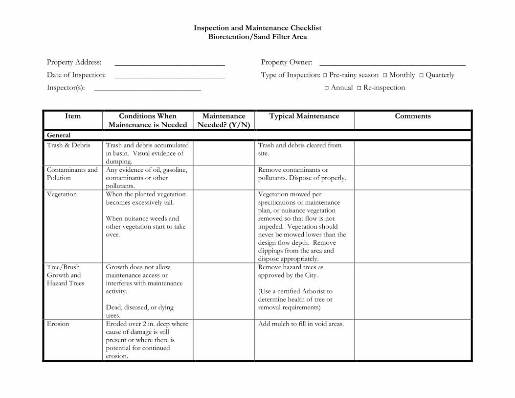
Inspection and Maintenance Checklist Bioretention/Sand Filter Area
Property Address: _______________________________ Property Owner: _________________________________________
Date of Inspection: _______________________________ Type of Inspection: □ Pre�rainy season □ Monthly □ Quarterly
Inspector(s): ______________________________ □ Annual □ Re�inspection
Item Conditions When Maintenance is Needed
Maintenance Needed? (Y/N)
Typical Maintenance Comments
General
Trash & Debris Trash and debris accumulated in basin. Visual evidence of dumping.
Trash and debris cleared from site.
Contaminants and Polution
Any evidence of oil, gasoline, contaminants or other pollutants.
Remove contaminants or pollutants. Dispose of properly.
Vegetation When the planted vegetation becomes excessively tall. When nuisance weeds and other vegetation start to take over.
Vegetation mowed per specifications or maintenance plan, or nuisance vegetation removed so that flow is not impeded. Vegetation should never be mowed lower than the design flow depth. Remove clippings from the area and dispose appropriately.
Tree/Brush Growth and Hazard Trees
Growth does not allow maintenance access or interferes with maintenance activity. Dead, diseased, or dying trees.
Remove hazard trees as approved by the City. (Use a certified Arborist to determine health of tree or removal requirements)
Erosion Eroded over 2 in. deep where cause of damage is still present or where there is potential for continued erosion.
Add mulch to fill in void areas.

Inspection and Maintenance Checklist Bioretention/Sand Filter Area (continued)
Property Address: _______________________________ Inspection Date: _____________________________________
Treatment Measure No.: _______________________________
Item Conditions When Maintenance is Needed
Maintenance Needed? (Y/N)
Typical Maintenance Comments
Sediment Accumulated sediment affects inletting or outletting condition of the facility.
Remove sediment. Reseed area.
Damaged Pipes Any part of the piping that is crushed or deformed more than 20% or any other failure to the piping.
Repair or replace pipe.
Rodent Holes If facility acts as a dam or berm, any evidence of rodent holes, or any evidence of water piping through dam or berm via rodent holes.
Repair damage until the design specifications are not compromised by holes. Rodent control activities must be in accordance with applicable laws and do not affect ay protected species.

Appendix 10.5 – Inspection & Maintenance Checklist – Vortex Systems
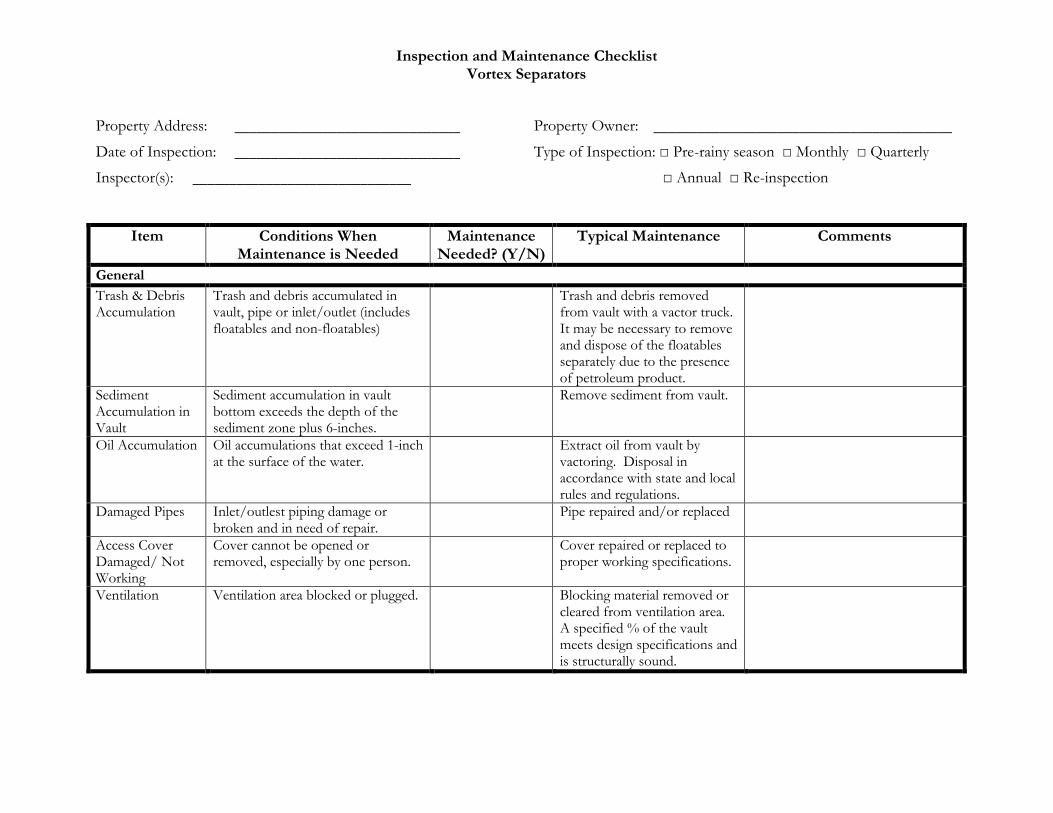
Inspection and Maintenance Checklist Vortex Separators
Property Address: _______________________________ Property Owner: _________________________________________
Date of Inspection: _______________________________ Type of Inspection: □ Pre�rainy season □ Monthly □ Quarterly
Inspector(s): ______________________________ □ Annual □ Re�inspection
Item Conditions When Maintenance is Needed
Maintenance Needed? (Y/N)
Typical Maintenance Comments
General
Trash & Debris Accumulation
Trash and debris accumulated in vault, pipe or inlet/outlet (includes floatables and non�floatables)
Trash and debris removed from vault with a vactor truck. It may be necessary to remove and dispose of the floatables separately due to the presence of petroleum product.
Sediment Accumulation in Vault
Sediment accumulation in vault bottom exceeds the depth of the sediment zone plus 6�inches.
Remove sediment from vault.
Oil Accumulation Oil accumulations that exceed 1�inch at the surface of the water.
Extract oil from vault by vactoring. Disposal in accordance with state and local rules and regulations.
Damaged Pipes Inlet/outlest piping damage or broken and in need of repair.
Pipe repaired and/or replaced
Access Cover Damaged/ Not Working
Cover cannot be opened or removed, especially by one person.
Cover repaired or replaced to proper working specifications.
Ventilation Ventilation area blocked or plugged. Blocking material removed or cleared from ventilation area. A specified % of the vault meets design specifications and is structurally sound.

Inspection and Maintenance Checklist Vortex Separators (continued)
Property Address: _______________________________ Inspection Date: _____________________________________
Treatment Measure No.: _______________________________
Item Conditions When Maintenance is Needed
Maintenance Needed? (Y/N)
Typical Maintenance Comments
Vault Structure Damage – Includes Cracks in Walls, Bottom, Damage to Frame and/or Top Slab
• Maintenance/inspection personnel determine that the vault is not structurally sound.
• Cracks wider then ½�inch at the joint of any inlet/outlet pipe or evidence of soil particles entering through the cracks.
• Vault replaced or repairs made so that vault meets design specifications and is structurally sound.
• Vault repaired so that no cracks exist wider than ¼�inch at the joint of the inlet pipe.
Baffles Baffles corroding, cracking warping and/or showing signs of failure as determined by maintenance, inspection staff.
Baffles repaired or replaced to specifications.
Access Ladder Damage
Ladder is corroded or deteriorated, not functioning properly, not securely attached to structural wall, missing rungs, has cracks and/or is misaligned confined space warning sign missing.
Ladder replaced or repaired to specifications, and is safe to use as determined by inspection personnel. Sign warning of confined space entry requirements clearly visible. Ladder and entry notification complies with OSHA standards.
Rubberizer® absorber pouches
Pouch solidifies into rubberized material.
Replace pouches.
Mosquito Vector Breeding
Suitable habitats exist for mosquito production (e.g., standing water in areas accessible to mosquitoes.
Standing water no longer exists or is inaccessible to mosquitoes.

Appendix 10.6 – Source & Treatment Control Operation & Maintenance Inspection Annual Report

Page | 1 Deer Creek Village
Source and Treatment Control Operation and Maintenance
Inspection Annual Report
This report and attached Inspection and Maintenance Checklists document the inspection and maintenance conducted for the identified storm water source and treatment control(s) that are subject to the maintenance mechanism that assigns responsibility for maintenance. The report covers the annual reporting period indicated below. Note: This Report is for bioretention units only. A separate Report will need to be prepared for Vortex Separators by qualified maintenance personnel.
I. Property Information:
Property Address or APN:
Property Owner:
II. Contact Information:
Name of person to contact regarding this report:
Phone number of contact person: Email:
Address to which correspondence regarding this report should be directed:
III. Reporting Period:
This report, with the attached completed inspection checklists, documents the inspections
and maintenance of the identified treatment measures during the time period from _______
to _______.
IV. Storm Water Source and Treatment Control Information:
The following storm water source and treatment controls are located on the property
identified above and are subject to the Agreement:
Identifying Number of Source and Treatment Control
Type of Source and Treatment Control
Location of Source and Treatment Control on the Property

Page | 2 Deer Creek Village
V. Summary of Inspections and Maintenance:
Summarize the following information using the attached Inspection and maintenances
Checklists:
Identifying Number of Source and Treatment Control
Date of Inspection
Operation and Maintenance Activities Performed and Date(s) Conducted
Additional Comments
VI. Sediment Removal:
Total amount of accumulated sediment removed from the storm water treatment measure(s)
during the reporting period: ________ cubic yards.
How was sediment disposed?
□ landfill □ Other location on3site as described in and allowed by the maintenance plan □ Other, explain ______________________
Page | 3 Deer Creek Village
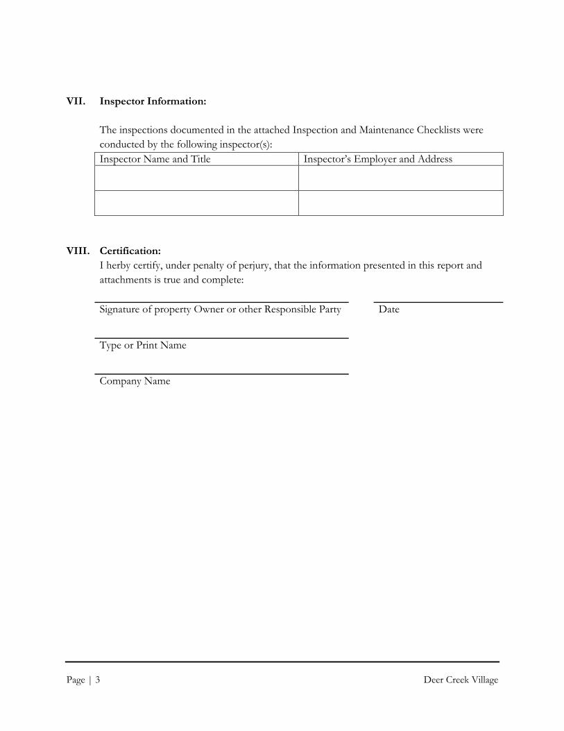
VII. Inspector Information:
The inspections documented in the attached Inspection and Maintenance Checklists were
conducted by the following inspector(s):
Inspector Name and Title Inspector’s Employer and Address
VIII. Certification:
I herby certify, under penalty of perjury, that the information presented in this report and
attachments is true and complete:
Signature of property Owner or other Responsible Party Date
Type or Print Name
Company Name

Appendix 10.7 – Storm Water Control Plan

© 2008
Sheet
Plan File:
File:
D�4862
591302�C3D
Prepared Under the Direction of:
California
State Of
Sonoma
County Of
City Of
DU
TR
A G
RO
UP
CSW/Stuber�Stroeh
45 Leveroni CourtNovato, CA 94949tel: 415.883.9850fax: 415.883.9835
Engineering Group, Inc.
RS
WR
SW
AG
C
Rev
Date
Description
Designed
Drawn
Checked
P:\0
5\59
1302
\DW
G_2
012\
Exh
ibit\
EX
40 S
torm
Wat
er M
anag
emen
t Pla
n_R
WQ
B.d
wg,
1/0
7/20
14 *
01:2
4 P
M, b
arcj
, 1
:2.2
326
Scale:
Date:
1" = 100'
05�08�12
Civil & Structural EngineersSurveying & Mapping
Environmental PlanningLand Planning
Construction ManagementLandscape Architecture
RS
WR
SW
AG
C
LANDING WAY WETLAND
DU
TR
A H
AY
ST
AC
K L
AN
DIN
G
AN
D P
OR
TIO
N O
F L
AN
DIN
G W
AY
AD
DIT
ION
AL
RE
VIS
ION
BA
SE
D O
N J
ULY
23, 2012
12
01
3�1
2�1
1

Appendix 10.8 – Owner’s Certification

Storm Water Control Operations & Maintenance Plan Deer Creek Village March 1, 2013
Owner’s Certification
The selection, sizing, and design of stormwater treatment and other control measures in this plan meet the requirements of Regional Water Quality Control Board Order R2*2003*0022 and subsequent amendments.
All stormwater treatment facilities will be inspected and maintained in accordance with this document.
Signed: __________________________________ Date: _____________
Title: ____________________________________