storm water quality management guidance manual€¦ · storm water quality management guidance...
TRANSCRIPT

STORM WATER QUALITYMANAGEMENT
GUIDANCE MANUAL
Prepared by
City of HoustonHarris County
Harris County Flood Control District
2001 Edition

Storm Water Quality Management i 2001 EditionGuidance Manual
TABLE OF CONTENTS
FORWARD vi
RECORD OF AMENDMENTS vii
1.0 INTRODUCTION
1.1 BACKGROUND 1 - 1
1.2 PURPOSES OF THE GUIDANCE MANUAL 1 - 2
1.3 ORGANIZATION OF THE MANUAL 1 - 3
1.4 DISCLAIMER 1 - 3
1.5 ACKNOWLEDGEMENTS 1 - 4
2.0 WATER QUALITY IMPACTS OF STORM WATER RUNOFF
2.1 URBANIZATION AND SURFACE WATER QUALITY 2 - 1
2.2 TYPES OF STORM WATER POLLUTANTS 2 - 1
2.3 URBAN LAND USE AND IMPACTS ON STORM WATER 2 - 3
3.0 STORM WATER QUALITY MANAGEMENT PLANS
3.1 STORM WATER QUALITY MANAGEMENT PLAN REQUIREMENTS 3 - 13.1.1 Site Description 3 - 13.1.2 Controls 3 - 23.1.3 Maintenance 3 - 23.1.4 Inspections 3 - 2
3.2 PREPARATION OF STORM WATER QUALITY MANAGEMENTPLAN 3 - 23.2.1 Collect Site Information 3 - 33.2.2 Develop the Preliminary Site Map(s) 3 - 43.2.3 Measure the Site Area and Drainage Areas 3 - 43.2.4 Select Controls 3 - 43.2.5 Prepare the Final Site Map and Narrative 3 - 123.2.6 Prepare the Inspection and Maintenance Plan 3 - 12
4.0 BEST MANAGEMENT PRACTICES
4.1 NON-STRUCTURAL CONTROLS 4 - 24.1.1 Household Hazardous Materials Storage/Disposal 4 - 24.1.2 Litter Control 4 - 74.1.3 Landscaping Practices 4 - 84.1.4 Fertilizer and Pesticide Use 4 - 94.1.5 Fueling Station Practices 4 - 124.1.6 Vehicle/Equipment Washing and Steam Cleaning Practices 4 - 144.1.7 Liquid Materials Loading and Unloading Practices 4 - 164.1.8 Liquids Storage in Aboveground Tanks Practices 4 - 19

Storm Water Quality Management ii 2001 EditionGuidance Manual
TABLE OF CONTENTS, continued
4.1.9 Container Storage of Liquids, Food Wastes, Hazardous Wastes 4 - 224.1.10 Spill Prevention and Response Plan 4 - 254.1.11 Outdoor Storage Practices 4 - 264.1.12 Street Sweeping 4 - 284.1.13 Inlet Stenciling 4 - 28
4.2 STORM WATER QUALITY BASINS 4 - 334.2.1 Dry Basins 4 - 344.2.2 Wet Ponds 4 - 634.2.3 Dual Use Flood Control/Water Quality Basin 4 - 714.2.4 Constructed Wetlands 4 - 76
4.3 INFILTRATION/FILTRATION FACILITIES 4 - 81
4.4 CATCHMENT FACILITIES 4 - 824.4.1 Catch Basin 4 - 824.4.2 Oil/Grit Separators 4 - 84
4.5 VEGETATIVE PRACTICES 4 - 904.5.1 Grassed Swales 4 - 904.5.2 Vegetated Filter Strips 4 - 93
4.6 LOW IMPACT DEVELOPMENT 4 - 95
5.0 ORDINANCE AND REGULATIONS

Storm Water Quality Management iii 2001 EditionGuidance Manual
APPENDICES
A. GUIDANCE FOR PLAN SUBMITTAL AND IMPLEMENTATION REVIEW
B. INSPECTION CHECKLISTS FOR NON-STRUCTURAL BEST MANAGEMENTPRACTICES (BMPS)
C. INSPECTION CHECKLISTS FOR STRUCTURAL BEST MANAGEMENTPRACTICES (BMPS)
D. PROPOSED COMPREHENSIVE MASTER PLANS FOR NEW DEVELOPMENTAND SIGNIFICANT REDEVELOPMENT (Superseded by City of HoustonOrdinance and Harris County Regulations)
E. RECOMMENDED PLANT LIST
F. ACRONYMS AND TERMS
G. REFERENCES
LIST OF TABLES
2.1 Range of Event Mean Concentrations and Land Use 2 - 43.1 Structural BMP Application 3 - 73.2 Applicable Non-Structural Controls 3 - 83.3 Non-Structural Control Matrix 3 - 94.1 Alternatives to Household Hazardous Materials 4 - 44.2 Disposal Chart 4 - 54.3 Fertilizer Suggestions 4 - 104.4 Household Alternatives to Toxic Pesticides 4 - 114.5 Typical Storm Sewer Sizes and Depths 4 - 354.6 Dry Basin Area Requirements 4 - 364.7 Slotted Slow Release Riser Pipes (Option B) 4 - 394.8 Orifice Plate Diameters 4 - 39B.1 Applicable Non-Structural Controls B - 2B.2 Non-Structural Controls Matrix B - 3

Storm Water Quality Management iv 2001 EditionGuidance Manual
LIST OF FIGURESFigure No. BMP Description
4.1 4.1.5 Details of Fuel Island 4 - 134.2 4.1.6 Requirements for an Uncovered Wash Area 4 - 154.3 4.1.7 Liquid Materials Loading and Unloading 4 - 184.4 4.1.8 Liquids Storage in Aboveground Tank Practices 4 - 214.5 4.1.9 Container Storage of Liquids, Food Wastes, Hazardous
Wastes 4 - 244.6 4.1.11 Outdoor Storage Practices 4 - 274.7a 4.1.15 Inlet Stenciling (Text and Graphic) 4 - 304.7b 4.1.15 Inlet Stenciling 4 - 314.8 4.1.15 Inlet Stenciling; Class “E” and “H-2” Manhole Cover 4 - 324.9a 4.2.1.1 In-Line Storm Sewer Basin: Weir Discharge 4 - 424.9b 4.2.1.1 In-Line Storm Sewer Basin: Weir Discharge Section A-A 4 - 434.9c 4.2.1.1 In-Line Storm Sewer Basin: Weir Discharge Alternative 4 - 44
Section A-A4.10a 4.2.1.1 In-Line Storm Sewer Basin: Internal Channel Discharge 4 - 454.10b 4.2.1.1 In-Line Storm Sewer Basin: Internal Channel Discharge
Section 4 - 464.10c 4.2.1.1 In-Line Storm Sewer Basin: Internal Channel Discharge
Notes 4 - 474.11a 4.2.1.1 In-Line Grass Linear Dry Ponds: Min. 10-Acre Site 4 - 484.11b 4.2.1.1 In-Line Grass Linear Dry Ponds: Riser Options 4 - 494.11c 4.2.1.1 In-Line Grass Linear Dry Ponds: Notes 4 - 504.12a 4.2.1.2 Storm Sewer Off-Line Basin 4 - 534.12b 4.2.1.2 Storm Sewer Off-Line Basin: Flow Splitter Detail 4 - 544.12c 4.2.1.2 Storm Sewer Off-Line Basin Notes 4 - 554.13a 4.2.1.3 In-Line Channel Basin 4 - 574.13b 4.2.1.3 In-Line Channel Basin: Notes 4 - 584.14a 4.2.1.4 Off-Line Channel Basin 4 - 614.14b 4.2.1.4 Off-Line Channel Basin: Notes 4 - 624.15 4.2.2 Potential Wet Pond Design 4 - 674.16a 4.2.2 In-Line Grass Swales, Wet Pond: Permanent Pool-Min.
10 Acre Site 4 - 684.16b 4.2.2 Wet Pond: Permanent Pool – Riser Options 4 - 694.16c 4.2.2 In-Line Grass Swales, Wet Pond: Permanent Pool - Notes 4 - 704.17 4.2.3 Potential Dual Use Flood Control/Water Quality Basin 4 - 744.18 4.2.3 Wet Pond: Riser Options 4 - 754.19a 4.2.4 Potential Wetland Design 4 - 794.19b 4.2.4 Potential Wetland Design Notes 4 - 804.20 4.4.1 Catch Basin Design Option 4 - 834.21 4.4.2 Oil/Grit Separator: SC-Type Separator 4 - 874.22 4.4.2 Oil/Grit Separator: API-Separator 4 - 884.23 4.4.2 Oil/Grit Separator: CPS-Separator 4 - 894.24 4.5.1 Grass Swale 4 - 924.25 4.5.2 Vegetated Filter Strip 4 - 944.26a 4.6 Conventional Site Plan 4 - 97

Storm Water Quality Management v 2001 EditionGuidance Manual
LIST OF FIGURESFigure No. BMP Description
4.26b 4.6 Modified Conventional Site Plan 4 - 984.27a 4.6 Low Impact Development Site Plan 4 - 994.27b 4.6 Low Impact Development Site Plan Notes 4 - 1004.28a 4.6 Low Impact Development Water Quality Treatment
Components 4 - 1014.28b,c 4.6 Low Impact Development Water Quality Treatment
Components Cross Sections 4 - 1024.28d 4.6 Low Impact Development: Bio-Filter 4 - 1034.29a 4.6 Conventional Lot 4 - 1044.29b 4.6 Low Impact Lot 4 - 1054.30 4.6 Low Impact Development: Bio-Retention 4 - 106

Storm Water Quality Management vi 2001 EditionGuidance Manual
FORWARD
This manual provides general guidance for permanent non-structural and structural controlsto reduce pollutants in storm water runoff from residential areas, commercial areas, lightindustrial areas, public facilities, and any industries not otherwise covered by EnvironmentalProtection Agency (EPA) storm water permits in Harris County and the City of Houston.The Storm Water Management Joint Task Force (JTF), which includes Harris County, HarrisCounty Flood Control District, and the City of Houston, has prepared this manual to satisfyNational Pollution Discharge Elimination System (NPDES) storm water permit requirementsestablished by EPA for storm water discharges from municipal separate storm sewer systems(MS4s). Emphasis is given to Best Management Practices (BMPs) that will work well inconditions specific to Harris County and the City of Houston. The manual providesinformation to owners, engineers, architects, and other citizens to facilitate the selection ofBMPs for storm water quality control and for compliance with local regulations whenadopted. The scope of this manual does not, however, include flood control designrequirements, or water quality controls for construction activities. Water quality controls forthe Texas Department of Transportation (TxDOT) rights-of-way are covered in a separatemanual prepared by TxDOT, also a member of the JTF.
NPDES STORM WATER WEBSITE
The Storm Water Management Joint Task Force (JTF) maintains an NPDES Storm Waterwebsite at the following address:
http://www.cleanwaterclearchoice.org/
Information on updates to the Storm Water Quality Management Guidance Manual will beposted at the above site.

Storm Water Quality Management vii 2001 EditionGuidance Manual
UPDATE MAILING LIST FORM
It is anticipated that this handbook will be updated periodically. If you are interested inreceiving information on future updates, please complete this form and mail to:
Storm Water Management Joint Task ForceP.O. Box 131066Houston, TX 77219
Name ____________________________________________________
Municipality or Firm ________________________________________
Address __________________________________________________
City __________________________ State _________ Zip _________
Comments__________________________________________________________________
___________________________________________________________________________
___________________________________________________________________________
___________________________________________________________________________
___________________________________________________________________________
___________________________________________________________________________
___________________________________________________________________________
___________________________________________________________________________
___________________________________________________________________________
___________________________________________________________________________
___________________________________________________________________________

Storm Water Quality Management viii 2001 EditionGuidance Manual
RECORD OF AMENDMENTS
This record sheet is provided to document and summarize amendments to the Storm Water Quality ManagementGuidance Manual.
Section PagesOld Pages
Removed ( )New PagesInserted ( )
RevisionDate Date

1.0
INTRODUCTION

Storm Water Quality Management 1 - 1 2001 EditionGuidance Manual
1.0 INTRODUCTION
1.1 Background
The 1972 amendments to the Federal Water Pollution Control Act (also referred to as theClean Water Act) prohibit the discharge of any pollutant to waters of the United Statesfrom a point source unless the discharge is authorized by a National Pollutant DischargeElimination System (NPDES) permit. Efforts to improve water quality under the NPDESprogram traditionally have focused on reducing pollutants in discharges of industrialprocess wastewater and from municipal sewage treatment plants. Efforts to addressstorm water discharges under the NPDES program have generally been limited to certainindustrial categories with effluent limitations for storm water.
Based in part on its national assessments, U.S. Environmental Protection Agency (EPA)has found that non-point sources (e.g., runoff from agriculture, silviculture, and miningactivities) and diffused point sources (e.g., storm water discharges from urbanized areas)are responsible for between one-third to two-thirds of existing and threatenedimpairments of the Nation’s waters.
Congress amended the Clean Water Act (CWA) in 1987 to require the EPA to establishphased NPDES requirements for storm water discharges. To implement theserequirements, on November 16, 1990, EPA published (55 Federal Register 47990) theinitial permit application requirements for (a) 11 categories of storm water dischargesassociated with industrial activity, and (b) discharges from municipal separate stormsewer systems (MS4s or public drainage systems) serving a population of 100,000 ormore.
The November 16, 1990 regulation established requirements of a two-part permitapplication designed to facilitate development of site-specific permit conditions for MS4sserving a population of 100,000 or more (e.g., the City of Houston, Harris County, theHarris County Flood Control District, and the Texas Department of Transportation). TheCWA requires that NPDES permits for storm water discharges from MS4s include arequirement to effectively prohibit non-storm water discharges into the MS4 and toinclude controls to reduce the discharge of pollutants to the maximum extent practicableby implementation of management practices, control techniques, engineering methods,and other provisions appropriate for the control of such pollutants.
In response to the EPA municipal storm water permit requirements, the City of Houston,Harris County, the Harris County Flood Control District, and the Texas Department ofTransportation (collectively, the “Permittees”) formed a Storm Water Management JointTask Force (Joint Task Force) to coordinate the preparation of the required permitapplications and compliance during permit terms. EPA issued a permit, Permit No.TXS001201 (the “permit”), to the Permittees effective October 1, 1998.
The permit requirements provide Permittees an opportunity to propose appropriatemanagement programs to control pollutants in discharges from their MS4s. Managementprograms required by EPA include implementing and maintaining structural and non-structural best management practices to reduce pollutants in storm water runoff fromillicit sources and from residential, commercial and industrial areas to the MS4. Inaddition to these management programs, the Permittees are also required to reduce stormwater runoff pollutants from construction sites.

Storm Water Quality Management 1 - 2 2001 EditionGuidance Manual
Additional regulatory developments in storm water quality include Phase II regulations,which address MS4s serving less than 100,000 in population, and construction sites thatdisturb one or more acres but less than five acres. EPA has separate requirements andguidance for the storm water management programs of Phase II entities. Pursuant to atimetable published by EPA, Phase II entities will be generally required to seek permitcoverage by March 2003. Accordingly, small construction sites that disturb one or moreacres but less than five acres are not addressed in this manual at this time. Furtherinformation on the upcoming regulations can be found at the EPA Phase II andConstruction Permit webpages at the following addresses:
http:\\www.epa.gov\owm\sw\phase2\
http:\\www.epa.gov\owm\sw\construction\index.htm
NPDES permitting authority was given to the Texas Natural Resource ConservationCommission (TNRCC) in 1999. New state regulations for MS4s will be promulgated inthe future by TNRCC under a TPDES program. Pursuant to a timetable published byEPA, TNRCC must issue permits for small MS4s (less than 100,000 population) byMarch 2003. It is anticipated that TNRCC will assume permitting responsibility for largeMS4s (100,000 population and over), including the Permittees, upon expiration of thecurrent MS4 permits. The Permittees’ NPDES permit expires on September 30, 2003.
1.2 Purposes of the Guidance Manual
This guidance manual has been prepared to provide guidance and criteria related to non-structural and structural controls to reduce pollutants in storm water runoff fromresidential areas, commercial areas, light industrial areas, and public facilities. Thisincludes industries not otherwise covered by EPA storm water permits. Guidance forcontrolling pollutants at construction sites is provided in a separate document entitled,Storm Water Management Handbook for Construction Activities, also prepared by theJoint Task Force. The purposes of this document are as follows:
(1) To satisfy NPDES storm water permit requirements established by EPA for stormwater discharges from the MS4.
(2) To be used in the jurisdictional areas of the City of Houston, Harris County and theHarris County Flood Control District as a guidance manual to facilitate compliancewith local requirements for new development and significant redevelopment. Notethat State highway rights-of-way under the jurisdiction of the Texas Department ofTransportation will be subject to a separate guidance document prepared by the TexasDepartment of Transportation.
The technical guidance and best management practices (BMP) described in this manualwill provide information to owners, engineers, architects, and other citizens to facilitatecompliance with local requirements for new development and significant redevelopment.It should be noted that the manual is not intended to be exhaustive, but to provide anoverview of the generally available options for storm water quality management in thisregion. Other options which may be applicable, depending on the site, are given in thesources cited. As a general guide, the manual discusses the considerations for selectingnon-structural and structural controls, design and maintenance criteria, and planrequirements.

Storm Water Quality Management 1 - 3 2001 EditionGuidance Manual
1.3 Organization of the Manual
This manual is organized to function as a user’s guide to meet the purposes previouslydescribed. The remainder of the manual is organized as follows:
• Section 2.0 provides an overview of the possible water quality impacts of stormwater runoff.
• Section 3.0 discusses the requirements of a Storm Water Quality Management Plan(SWQMP) including considerations for the selection of structural and non-structuralBMPs.
• Section 4.0 provides information for various structural and non-structural BMPsincluding planning considerations, design criteria and maintenance requirements.
• Section 5.0 provides information on obtaining copies of the City of Houstonordinance and Harris County regulations pertaining to the control of storm waterdischarges from new development and significant redevelopment.
• Appendix A - Guidance for Plan Submittal and Implementation Review• Appendix B - Inspection Checklists for Non-Structural (Source Control) Best
Management Practices• Appendix C - Inspection Checklists for Structural and Vegetative Best Management
Practices• Appendix D – Proposed Comprehensive Master Plans for New Development and
Significant Redevelopment (Superseded by City of Houston Ordinance andHarris County Regulations)
• Appendix E – Recommended Plant List• Appendix F – Acronyms and Terms• Appendix G - References
1.4 Disclaimer
This guidance manual is intended to provide general guidance in managing post-construction storm water discharge from sites of new development and significantredevelopment. The technical and guidance data included in this manual have come froma number of sources. (See Appendix G.) Careful consideration must be given toselecting the most appropriate control measures based on project-specific features. Additional information from professionals, agencies, organizations, and institutions withexpertise in a particular area may be required in selecting, designing, and installing theBMPs.
This guidance manual does not describe all of the requirements for storm water qualitymanagement. It is the responsibility of project sponsors, designers, and operators to havea thorough understanding of the storm water quality regulations and guidelines as theyare adopted and promulgated by the agency or agencies with jurisdiction.
As stated in the Purposes of the Guidance Manual, this document was prepared as aguidance manual and is not intended to replace the need for a site-specific plan for post-construction project activities. Use of information in this document is at the sole risk ofthe users. Harris County, Harris County Flood Control District, the City of Houston,Texas Department of Transportation and their agents and consultants do not represent

Storm Water Quality Management 1 - 4 2001 EditionGuidance Manual
that material contained in this document is adequate for compliance with local stormwater quality requirements or that it is accurate in all respects. Note that TxDOT isdeveloping its own guidance manual for highway development.
1.5 Acknowledgements
This guidance manual contains information provided from manuals developed in othercities and states. A reference list is included in Appendix G. Permission to use materialfrom their handbooks/manuals was granted by the Florida Department of EnvironmentalRegulation, Metropolitan Washington Council of Governments, Lower Colorado RiverAuthority Environmental Quality Division, Washington State Department of Ecology,and the Galveston Bay National Estuary Program, and is gratefully acknowledged. TheMetropolitan Washington Council of Governments has an information number for theirpublications and other information, at (202) 962-3256, or write to: Information Center,Metropolitan Washington Council of Governments, 777 North Capitol Street N.E., Suite300, Washington, D.C. 20002-4201.
The preliminary draft of this manual, published in October 1992, was distributed to morethan 40 organizations and public groups for review. A second draft was published onApril 29, 1993 for submittal to EPA. EPA accepted the April 1993 draft with theapproval of the JTF’s NPDES permit in 1998. The April 1993 draft was distributed forpublic comment in April 1999. The Storm Water Management Joint Task ForceTechnical Advisory Committee (TAC) also provided input to this manual and reviewedcomments from the public. The Joint Task Force is grateful to members of the TAC andto various organizations for their effort in reviewing the draft document. As this manualcontinues to be updated, public input will be an important part of the revision process.
Technical Advisory Committee:
Representative OrganizationMr. Ronnie Mullinax, P.E.(Chairperson)
Association of Consulting Municipal Engineers(ACME)
Mr. Don Conrad Houston Contractors Association (HCA)Mr. Theo Glanton, P.E. Water Environment Association of Texas (WEAT)Mr. Michael Schaffer Greater Houston Builders Association and Houston
Real Estate Council (GHBA/HREC)Mr. Gary Struzick, P.E. American Society of Civil Engineers (ASCE)Mr. Robert Taylor, A.I.A., P.E. American Institute of Architects (AIA)Ms. Mary Ellen Whitworth, P.E. Bayou Preservation Association (BPA)
Joint Task Force Agencies:
City of Houston Harris County Flood Control DistrictHarris County Texas Department of Transportation
Consultant to the Joint Task Force:
Turner Collie & Braden Inc.

2.0
WATER QUALITY IMPACTS OF STORM WATER RUNOFF

Storm Water Quality Management 2 - 1 2001 EditionGuidance Manual
2.0 WATER QUALITY IMPACTS OF STORM WATER RUNOFF
2.1 Urbanization and Surface Water Quality
Urbanization tends to increase runoff from previously undeveloped areas. Surface areafor infiltration is reduced by removing vegetation and increasing the extent of imperviousareas. Reduced vegetation also reduces evapotranspiration. Natural surface depressionswhich previously provided storm water storage are cleared and graded smooth. As aresult, runoff volumes, flow rates and flow velocities may increase significantly. Theimpacts and control measures for increased storm water quantities are addressed indrainage design manuals prepared by Harris County Flood Control District and the Cityof Houston.
Urban development generates short-term land disturbance and long-term land useintensification. These factors can contribute to reduced water quality. Storm Waterpollutants can be generated during construction and after construction from the operationand activities of urban land use. Urban land uses include residential, commercial,industrial, transportation, public and other uses. Urban land use activities may generatewastes and residuals that, if handled improperly, can pollute storm water runoff. Increased runoff volumes and velocities from impervious areas also can increase offsitepollutant transport, further impacting receiving waters. This guidance manual focuses onthe storm water quality impacts of urban land use activities after site stabilization, and thedevelopment of appropriate control measures.
2.2 Types of Storm Water Pollutants
Pollutants generated by urban land uses can be classified as floatables, sediment,nutrients, oxygen demand, oil and grease, heavy metals, toxic chemicals and bacteria. The causes and effects of these pollutants are summarized below.
Floatables:Floatable debris includes plastic and paper products, yard refuse, metal and glasscontainers, tires, etc. These pollutants are relatively large, decompose slowly anddegrade the visual aesthetics of the receiving waters and shorelines. They present aphysical danger to vegetation and wildlife, through habitat congestion, entangling oringestion. These pollutants originate from litter and improperly disposed refuse.
Sediment:Suspended sediment in high concentrations can cause multiple impacts. Impacts inreceiving streams may include increased turbidity, reduced light penetration, reducedprey capture for sight feeding predators, clogging of gills/filters of fish and aquaticinvertebrates, and reduced angling success. Impacts in slower receiving waters such aslakes and estuaries include siltation, with subsequent smothering of benthic communities,changes in bottom substrate composition, and decreased depth (creating a need fordredging). Sediment with high clay or organic content efficiently carries trace metals andtoxicants, posing a risk to benthic life upon resuspension.
Sedimentation impacts are affected by a number of interrelated site factors, including soiltypes, topography, surface cover and climate. The predominantly clayey soils in theHouston region have low permeability, which can result in increased runoff rates andvelocities. While the flat topography of the area helps reduce the scouring effects of

Storm Water Quality Management 2 - 2 2001 EditionGuidance Manual
higher velocities, it does, however, encourage siltation. Generally, the climate of the areapromotes the establishment of vegetative cover which can shield the soil and promoteinfiltration. However, the climates of coastal regions in Texas are subject to stormsranging from localized showers and intense thunderstorms to hurricanes.
Nutrients:Increased phosphorus and nitrogen levels can accelerate eutrophication in downstreamfresh and tidal waters. Eutrophication can lead to surface algal scums, waterdiscoloration, odors, depressed oxygen levels, and release of toxins.
Nutrients tend to build-up on impervious surfaces. Runoff from these areas can lead tohigh nutrient loads. Intensively landscaped areas and wash water from outdoor cleaningactivities are also potential sources of nutrients.
Oxygen Demand:Dissolved oxygen (DO) is an indicator of water quality impact. To support aquatic life,sufficient DO must be available. Decomposition of organic matter by microorganismsdepletes DO levels, especially in slower moving streams, lakes and estuaries. Risingtemperature from changing weather can also deplete DO by decreasing the solubility ofoxygen in water.
The degree of potential DO depletion from organic matter and microorganisms ismeasured by either the biochemical oxygen demand (BOD) test or the chemical oxygendemand (COD) test. Urban runoff can depress DO levels after large storms. BOD solidscan accumulate in bottom sediment during storms causing anoxic (zero oxygen)conditions in shallow, slow-moving or poorly flushed receiving waters.
Generally, the greatest export of BOD is from leaking sanitary sewer systems (i.e.,sewage overflow) and is therefore more often found in highly populated areas with olderinfrastructure. Even newer, low density suburban residential development can exportmoderate levels of BOD.
Oil and Grease:Oil and grease contain a wide variety of hydrocarbons, some of which are toxic to aquaticlife at low concentrations. Surface sheen is usually an indication of the presence ofhydrocarbons. However, some hydrocarbons, especially weathered crankcase oil, appearin solution or emulsion and have no sheen. Hydrocarbons have a strong affinity forsediment, and much of the hydrocarbon load adsorbs onto particles and settles out. If notcaptured, hydrocarbons tend to accumulate in bottom sediments of lakes and estuaries.
The major source of hydrocarbons is leakage from crankcase oil and other lubricatingagents from the automobile. Hydrocarbon levels generally are highest in runoff fromparking lots, roads and service stations. Residential land uses typically generate lesshydrocarbon export, with the exception of illegal dumping of used oil in storm sewers.
Heavy Metals:Trace heavy metals are a concern because of their toxicity to aquatic life and thepossibility of water supply contamination. The heavy metals with the highestconcentrations in urban runoff are copper, lead, zinc, and cadmium. Other heavy metalsmay be found when inappropriate connections between sanitary and storm sewers are

Storm Water Quality Management 2 - 3 2001 EditionGuidance Manual
present. Most heavy metals adsorb to particulates, which settle out and reduce the metalsimmediately available for biological uptake.
Substantial sources of lead in the past have been leaded gasoline and lead-based paints. As alternative fuels and paints have been developed, lead has become less common.
Toxic Chemicals:Other toxic chemicals present in urban runoff include pesticides, herbicides and syntheticorganic compounds. Concentrations of these substances in runoff from residential andcommercial areas rarely exceed current safety criteria. However, relatively littlesampling of runoff has been reported from industrial areas, which might be a greatersource of toxicants. Sources of pesticides, herbicides and other toxic compounds includeillegally disposed or applied household hazardous wastes, such as waste oil, paintthinners, pesticides, herbicides and preservatives. (USEPA 1992a, MWCOG 1987)
Bacteria:Bacteria levels in undiluted urban runoff usually exceed public health standards for watercontact recreation. Bacteria multiply faster during warm weather, and substantialdifferences in bacteria populations are to be expected between summer and winter. Thebacteria test, however, is a count of coliform bacteria, which are an indirect and oftenimprecise indicator of pathogens and viruses which may be present. Thus, the healthimplications may be unclear. Nonetheless, while most urban land uses export enoughbacteria to exceed health standards, older and more intensively developed urban areasgenerally produce the greatest export. The problem is especially significant in areas thatexperience sanitary sewer overflows that export bacteria derived from human wastes. Areas with improperly maintained or failed septic tank systems are also potentiallysignificant.
Sources: USEPA 1992a, MWCOG 1987, Wanielista, GBNEP 1991, Harris County,Harris County Flood Control District, City of Houston, USEPA 1980 andWinslow & Associates (1986).
2.3 Urban Land Use and Impacts on Storm Water
The impacts on storm water runoff from urban land use depend on the extent of landdevelopment, and the operations and activities of the land use. Storm water pollutantloads vary depending on the duration, intensity and frequency of individual rainfallevents and more generally, on the regional climate. Studies indicate a high variability ofloading rates in relation to land use and within land use categories. Table 2.1 providesdata on Event Mean Concentrations (EMC) from several sources. EMCs representaverage pollutant concentrations in the runoff from a storm event. The data are from theCity of Houston, Harris County, and Harris County Flood Control District Part 2 NPDESpermit application. The City of Houston, Harris County and Harris County FloodControl District will be conducting further studies on EMCs as part of their NPDESpermit.

Storm Water Quality Management 2 - 4 2001 EditionGuidance Manual
Table 2.1 - Range of Event Mean Concentrations and Land Use(mg/l)
Land Use BOD5Total
SuspendedSolids
TotalNitrogen
TotalPhosphorus
Oil andGrease
Undeveloped 2-13 22-565 0.66-50.20 0.10-.35 1.0-2.0
Residential
Commercial/Industrial
2-24
4-36
8-1340
5-459
0.72-49.70
0.44-33.00
0.08-.98
0.06-.47
1.0-6.0
1.0-12.0
Source: City of Houston, Harris County and Harris County Flood Control District Part 2 NPDES permit application addendum, April1993.

3.0
STORM WATER QUALITY MANAGEMENT PLANS
Storm Water Quality Management 3 - 1 2001 EditionGuidance Manual
3.0 STORM WATER QUALITY MANAGEMENT PLANS (SWQMPs)
As required by the NPDES permit, the City of Houston prepared the Proposed ComprehensiveMaster Plan for New Development and Significant Redevelopment in the City of Houston (the“Master Plan” for the City of Houston), and Harris County/Harris County Flood Controlprepared the Proposed Comprehensive Master Plan for New Development and SignificantRedevelopment in Harris County (Unincorporated Areas), (the “Master Plan” for Harris County). The master plans were the basis for the City of Houston ordinance and Harris Countyregulations. The ordinance and regulations require controls to reduce pollutants in discharges tothe municipal separate storm sewer system (MS4) after the construction of a development iscompleted.
Under the ordinance and regulations, proposed new development and significant redevelopmentof 5 or more acres will be required to submit Storm Water Quality Management Plans(SWQMPs) that propose structural, non-structural or vegetative controls to reduce pollutants instorm water runoff. The overall goal of the ordinance and regulations and the goal of SWQMPsis to reduce the discharge of pollutants into the municipal separate storm sewer system to theMaximum Extent Practicable (MEP). This manual is intended to provide guidance on thepreparation of SWQMPs.
This section describes general planning and implementation procedures for SWQMPs forresidential development, commercial development, light industrial development, public facilitydevelopment, and significant redevelopment of five or more acres. These are general guidelines,and specific site conditions may require additional or modified measures or approaches. TheSWQMP requirements discussed here address pollution arising from post-construction activities.The intended function of an SWQMP is to improve storm water quality from the normal dailyoperating activities of a site for the life of the development. The preparation of Storm WaterPollution Prevention Plans (SWPPPs) for storm water pollution prevention during construction isaddressed in a separate guidance document, the Storm Water Management Handbook forConstruction Activities. Other types of development/redevelopment projects for facilities that areregulated by EPA’s industrial storm water permitting program should provide storm waterquality control measures as required by the EPA.
3.1 Storm Water Quality Management Plan Requirements
The SWQMP functions as a mitigation plan for the potential impacts of pollution fromstorm water discharge from the normal operating activities of a site for the life of thedevelopment. The SWQMP should contain a site description, planned controls, andprocedures for maintenance and inspection. The contents of an SWQMP are describedbelow.
3.1.1 Site Description
A. Site location.B. Names, addresses and phone numbers of owner and contact person.C. Type of development or redevelopment.D. Nature of activities (Including Standard Industrial Classification Codes).E. Give any existing NPDES storm water permit numbers or provide a copy of the
General Permit Notice of Intent (NOI) or NPDES permit application. If the NPDESpermit application or NOI is not available, a statement of intent to file an NOI or

Storm Water Quality Management 3 - 2 2001 EditionGuidance Manual
NPDES permit application should be provided, and a copy of the NPDES permit orNOI, when it is available, should be submitted.
F. Estimates of the total site area and the total area affected by the development.G. Site map(s).
1. Vicinity map.2. Areas of development.3. Areas not to be developed.4. Drainage areas and their acreage, patterns and approximate slopes anticipated
after development.5. Wetlands and surface waters.6. Locations and listing of activities which may generate pollutants and potential
discharge, including hazardous materials treatment, storage or disposal facilities,parking areas, loading areas, etc.
7. Locations and listing of structural controls, and non-structural controls asapplicable, that are identified in the plan.
8. Locations where storm water is discharged to the MS4 and the name of the MS4operator.
3.1.2 Controls
A. Non-Structural ControlsDescribe non-structural best management practices (BMPs) and how they will beused at the site.
B. Structural ControlsStructural BMPs should be shown on construction drawings. Supporting data (e.g.,specifications, calculations, etc.) should be provided upon request.
3.1.3 Maintenance
Describe procedures and qualified personnel to assure the timely maintenance of controlmeasures.
3.1.4 Inspections
Describe inspection reporting and procedures.
3.2 Preparation of Storm Water Quality Management Plan (SWQMP)
The SWQMP should be developed in the early planning stages of a project so that the siteplan can be prepared with provisions for water quality management. The SWQMP needsto be developed at a stage when site data and preliminary site plan(s) are available asbackground and working information. Pollution prevention principles to consider whendeveloping the physical site plan for the project include the following:
• Use vegetation and ground cover as a method of natural filtration of runoff.• Minimize the amount of land disturbance (i.e., clearing, grading and excavation).• Avoid disturbing sensitive areas such as wetlands, steep or unstable slopes, and areas
with erodible soils.• Coordinate the permanent BMPs with those used during construction (e.g., swales,
basins, vegetated areas, etc.)

Storm Water Quality Management 3 - 3 2001 EditionGuidance Manual
• Reduce or alter activities to those that minimize the potential of storm waterpollution.
• Enclose or cover pollution-causing activities to minimize the potential of storm waterpollution.
At the heart of the SWQMP is the selection and implementation of a BMP or set ofBMPs for water quality management.
BMPs are generally grouped into two categories:
• Non-structural Controls• Structural Controls
Non-structural controls are primarily management-based activities that are generallydesigned to prevent or reduce the potential of storm water runoff contact with pollution-causing activities. Selection of non-structural controls is then based on land use activity.
Structural controls are constructed facilities or vegetative practices that are generallydesigned to reduce pollutant levels in storm water runoff. Targeted pollutants include:particulates, pollutants that bond to particulates (heavy metals), nutrients (phosphorus,nitrogen), oil and grease, oxygen demand, and to a limited extent, bacteria. Initialconsideration of structural controls is based on site area. If the site drainage area(s) isless than 10 acres, vegetative practices may be used. If the drainage area(s) is 10 or moreacres, vegetative practices may be used with other needed structural controls. The waterquality detention basin is the primary structural control method for areas of 10 or moreacres. For any site of 5 or more acres, a program of non-structural controls may be usedon a case-by-case basis as an alternative to structural controls.
A general process for preparing a SWQMP is as follows.
Step 1 Collect site information. Step 2 Develop the preliminary site map. Step 3 Measure the site area and drainage area(s) to determine the type of controls
needed. Step 4 Select non-structural and structural controls. Step 5 Prepare the final site map and narrative. Step 6 Prepare the inspection and maintenance plan.
Each step is discussed in detail below.
3.2.1 Collect Site Information
Collect information related to the site which will be developed. The following items aresuggested.
A. Map of Existing Conditions A map of existing conditions at the site should be prepared. The map should betopographic and to scale. The map should indicate existing activities at the site aswell as the locations of surface waters at or near the site. The map scale should beadequate to allow important features such as grassed swales and control measures tobe distinguished easily.
B. Location of Discharge Point(s)

Storm Water Quality Management 3 - 4 2001 EditionGuidance Manual
The MS4 which will receive runoff from the proposed development site should beidentified.
3.2.2 Develop the Preliminary Site Map(s)
Develop a preliminary site map or maps. This may involve evaluation and refinement ofthe site plan for the proposed development.
When the preliminary site map or maps are complete, the following information shouldbe included:
• Building outlines and impervious areas.• Locations of activities which may generate pollutants.• Locations of outfalls and possible discharges.• Drainage areas, drainage patterns and contours. Approximate slopes after grading.
Locations of sheet flow and concentrated flow should be shown.• Proposed drainage facilities, including channels, pipes and detention basin(s).
Indicate existing surface water and wetlands.• Landscaping areas and preserved vegetation.• Larger facilities that will be used during construction for the construction pollution
prevention plan, and to be built early in the construction sequence such as sedimentbasins, sediment traps, etc.
3.2.3 Measure the Site Area and Drainage Areas
Estimate the total site area and the drainage areas. The total area of the site shouldinclude the area inside the project's property boundaries, easements, and rights-of-way. The size of the drainage area for each point where concentrated flow will leave the siteshould be determined. If the site drainage area(s) is less than 10 acres, vegetativepractices may be used. If the drainage area is 10 or more acres, other structural controlsare needed. For any site of 5 or more acres, a program of non-structural controls may beused on a case-by-case basis as an alternative to vegetative or structural controls.
3.2.4 Select Controls
Determine areas of potential storm water pollution and the feasibility of using structuralor non-structural controls. General practices for structural and non-structural controls arelisted below, and are addressed in detail in Section 4.0. For certain types of developmentas specified in the Master Plan, a program of non-structural controls may be used as analternative to or in addition to structural controls. Site conditions should be carefullyevaluated before applying these practices. Conditions specific to a site will requireadaptation, or may restrict use of some of the practices. Site conditions may allow otherpractices not included in this list, and innovation is encouraged in developing suchtechnologies for storm water quality management.
Structural Controls: Storm Water Quality Facilities:1. Dry basin2. Wet basin3. Wetland treatment4. Other site-specific alternative

Storm Water Quality Management 3 - 5 2001 EditionGuidance Manual
Catchment Facilities:1. Catch basins2. Oil/grit separator3. Other site-specific alternative Vegetative Practices:1. Vegetated filter strip2. Grassed swale3. Other site-specific alternative
Non-Structural Controls:1. Household hazardous materials storage/disposal2. Litter control3. Landscaping practices4. Fertilizer and pesticide use5. Fueling station practices6. Vehicle/equipment washing and steam cleaning practices7. Liquid materials loading and unloading practices8. Liquids storage in aboveground tanks9. Container storage of liquids, food wastes, and hazardous wastes10. Spill Prevention and Response plan11. Outdoor storage practices12. Street sweeping13. Inlet Stenciling14. Other Controls (activities, programs, etc.)
3.2.4.1 Selection of Structural Controls
Structural controls are constructed facilities or vegetative practices that are designed toreduce pollutant levels in storm water runoff. Structural controls may be preliminarilyselected based on drainage area. However, drainage area is only one of the factors toconsider in selecting BMPs. Other considerations that may be important to the selectionof structural controls include area requirements for the water quality facility, soil typeand condition, vegetative and impervious cover, and type of expected pollutant from thesite. Vegetative practices may be used for drainage areas of less than 10 acres. Fordrainage areas of 10 acres or more, water quality basins (i.e., dry basins, wet basins, etc.)are the main forms of structural control and should be used where attainable.
Impervious cover changes replace natural vegetation and open space with built facilitiesand manmade landscapes. This can affect site hydrology and biofiltration and processingmechanisms, which ultimately impact storm water quantity and quality. The result maybe increased pollutants from the site due to more intense activity and larger storm waterflows which transport the pollutants off the site.
Impervious cover may contribute to reduced habitat value of streams. Pollutants aredeposited from the atmosphere, oil drips from cars on parking lots, and organic matteraccumulates and runs off. Also, heavy metals that are common components ofimpervious covers such as metal roofing, downspouts, and galvanized pipes can corrode,leach out, and runoff into streams. Once introduced into the waterways, the pollutantscan be carried downstream and can have adverse impacts on aquatic species.

Storm Water Quality Management 3 - 6 2001 EditionGuidance Manual
When combined with intense rainfall events, the flat regional topography can producehigh storm water runoff volumes. A relatively large amount of land could then be neededfor the water quality basin, even when the actual pool area may be small. The differenttypes of water quality basins have different benefits and costs. For example, wet basinstypically have high amenity value but may be vulnerable to high sediment loads. Wetland treatment may be appropriate with large, level areas, and have high habitatvalue. Structural BMP applications are summarized in Table 3.1.
For planning purposes, an important consideration is whether detention will be requiredin addition to storm water quality control. It may be possible to design detentionfacilities to capture and release the first flush (the first 0.5-inch of runoff) over a 24 to 48hour period and also provide effective storm water quantity control. Preliminary volumeand surface area requirements of structural controls can be estimated from the drainagearea and required runoff storage.

Storm Water Quality Management 3 - 7 2001 EditionGuidance Manual
TABLE 3.1
STRUCTURAL BMP APPLICATION
BMP Drainage AreaGuidelines
Other Considerations SectionNumber
Dry Basin N/A • Large surface area.• Potentially extensive excavation in
flat areas.• Sediment testing and removal
required.
4.2.1
Wet Basin N/A • Potential amenity value.• Large surface area.• Potentially extensive excavation in
flat areas.• Affected by high sediment loads.• Sediment testing and removal
required.
4.2.2
Wetland Treatment N/A • Potential habitat value.• Large surface area.• Affected by high sediment loads.• Requires careful design by
wetland specialist.• Sediment testing and removal
required.
4.2.4
Catch Basins (N/A -included withsewer inlet design)
• Not a stand-alone BMP but maybe used with other BMPs
• Frequent maintenance.
4.4.1
Oil/Grit Separators ≤ 5 acres • High cost relative to size ofdrainage area served.
• Frequent inspection andmaintenance.
• For small drainage areas(maximum 5 acres).
• Particularly vulnerable to highsediment loads.
4.4.2
Grassed Swales ≤ 10 acres
(>10 acres willrequire additional
structuralcontrol(s).)
• Unsuitable for slopes > 5%.• Requires careful design when near
foundation.• Particularly vulnerable to high
sediment load.• Less effective in areas with high
water table, due to lessexfiltration.
4.5.1
Vegetated Filter Strips ≤ 10 acres
(>10 acres willrequire additional
structuralcontrol(s).)
• For 10% or flatter slopes.• Requires careful design when near
foundation.• Particularly vulnerable to high
sediment load.• Less effective in areas with high
water table, due to lessexfiltration.
4.5.2

Storm Water Quality Management 3 - 8 2001 EditionGuidance Manual
3.2.4.2 Selection of Non-Structural Controls
Table 3.2 lists typical pollutant-causing activities that could after development along withpotential non-structural controls that may be appropriate to address those activities. Thiscould be used as preliminary aid to evaluate applicable non-structural controls.
Table 3.3 lists different land use categories and possible applicable non-structuralcontrols, based on generalized cases contained in the referenced sources in Appendix G. The purpose of the table is to show how non-structural controls can be used in thesecases. The appropriateness and specific application of a control or set of controls willdepend on site conditions. The table is not exhaustive and additional land uses andcontrols could be included.
Table 3.2 – Applicable Non-Structural Controls
Potential Pollutant-Causing Activity ActivityLocated onSite ( )
Applicable Non-Structural Control Ref. #
Uncovered vehicle parking Street Sweeping 4.1.12Trash disposal Litter Control 4.1.2Washing of vehicle or equipment Vehicle/Equipment Washing and Steam
Cleaning4.1.6
Vehicle or equipment fueling Fueling Station 4.1.5Loading or unloading of liquidmaterials
Liquid Materials Loading and Unloading 4.1.7
Storage of raw materials, by-productsor products of manufacturingprocesses
Outdoor StorageOutdoor ManufacturingSpill Prevention and Response Plan
4.1.114.1.124.1.10
Above-ground bulk storage of fuel,petroleum or chemicals
Liquids Storage in Aboveground TanksLiquid Materials Loading and UnloadingSpill Prevention and Response Plan
4.1.84.1.74.1.10
Underground tanks Liquid Materials Loading and UnloadingSpill Prevention and Response Plan
4.1.74.1.10
Use of pesticides or fertilizers Household Hazardous MaterialsStorage/DisposalLandscaping PracticeFertilizer and Pesticide Use
4.1.1a4.1.24.1.4
Temporary storage of liquid or solidwastes Type of waste:
Hazardous waste
Food waste
Used oil/antifreeze
Underground drainage system
Liquids Storage in Aboveground Tanks
Container Storage of LiquidsSpill Prevention and Response PlanContainer Storage of LiquidsSpill Prevention and Response PlanContainer Storage of LiquidsSpill Prevention and Response PlanHousehold Hazardous MaterialsStorage/Disposal (recycling oil/antifreeze)Inlet Stenciling
4.1.8
4.1.94.1.104.1.94.1.104.1.94.1.10
4.1.1a4.1.13
ANY OTHER ACTIVITIES NOT COVERED ABOVE:

TABLE 3.3: NON-STRUCTURAL CONTROL MATRIX
Household Hazardous Materials Storage/Disposal (4.1.1)Litter Control (4.1.2)
Landscaping Practices (4.1.3)Fertilizer and Pesticide Use (4.1.4)
Fueling Station Practices (4.1.5)Vehicle/Equipment Washing and Steam Cleaning Practices (4.1.6)
Liquid Materials Loading and Unloading Practices (4.1.7)Liquids Storage in Above Ground Tanks (4.1.8)
Container Storage of Liquids, Food Wastes, Hazardous Wastes (4.1.9)Spill Prevention and Response Plan (4.1.10)
Outdoor Storage Practices (4.1.11)Street Sweeping (4.1.12)
Storm W
ater Quality M
anagement
Guidance M
anual
Inlet Stencilling (4.1.13)
LAND USE:
MANUFACTURING BUSINESSES:
Cement
Chemicals
3 - 9
Concrete Products
Electrical Products
Food Products
Glass Products
Machinery And Equipment
Metal Products
Paper And Pulp Mills
Paper Products
Petroleum Products
Printing And Publishing
Rubber And Plastic Products
Ship And Boat Building/Repair Yards
Wood Products
Wood Treatment
TRANSPORTATION AND COMMUNICATION:
2001 Edition
Airfields/Aircraft Maintenance

TABLE 3.3: NON-STRUCTURAL CONTROL MATRIX, continued
Household Hazardous Materials Storage/Disposal (4.1.1)Litter Control (4.1.2)
Landscaping Practices (4.1.3)Fertilizer and Pesticide Use (4.1.4)
Fueling Station Practices (4.1.5)Vehicle/Equipment Washing and Steam Cleaning Practices (4.1.6)
Liquid Materials Loading and Unloading Practices (4.1.7)Liquids Storage in Above Ground Tanks (4.1.8)
Container Storage of Liquids, Food Wastes, Hazardous Wastes (4.1.9)Spill Prevention and Response Plan (4.1.10)
Outdoor Storage Practices (4.1.11)Street Sweeping (4.1.12)
Storm W
ater Quality M
anagement
Guidance M
anual
Inlet Stencilling (4.1.13)
Fleet Vehicle Yards
Railroads
Private Utility Corridors
Warehouses And Miniwarehouses
3 - 10
WHOLESALE AND RETAIL BUSINESSES:
Gas Stations
Recyclers And Scrap Yards
Restaurants/Fast Food
General Merchandise
Vehicle And Equipment Dealers
Nurseries And Building Materials
Chemicals And Petroleum
Foods And Beverages
SERVICE BUSINESSES:
Commercial Car And Truck Washes
Equipment Repair
Laundries And Cleaning Services
Marinas And Boat Clubs
Professional Services
Vehicle Maintenance/Repair
Construction Businesses
2001 Edition
SINGLE FAMILY RESIDENCES
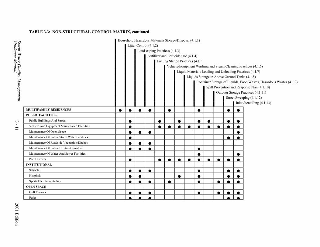
TABLE 3.3: NON-STRUCTURAL CONTROL MATRIX, continued
Household Hazardous Materials Storage/Disposal (4.1.1)Litter Control (4.1.2)
Landscaping Practices (4.1.3)Fertilizer and Pesticide Use (4.1.4)
Fueling Station Practices (4.1.5)Vehicle/Equipment Washing and Steam Cleaning Practices (4.1.6)
Liquid Materials Loading and Unloading Practices (4.1.7)Liquids Storage in Above Ground Tanks (4.1.8)
Container Storage of Liquids, Food Wastes, Hazardous Wastes (4.1.9)Spill Prevention and Response Plan (4.1.10)
Outdoor Storage Practices (4.1.11)Street Sweeping (4.1.12)
Storm W
ater Quality M
anagement
Guidance M
anual
Inlet Stencilling (4.1.13)
MULTIFAMILY RESIDENCES
PUBLIC FACILITIES
Public Buildings And Streets
Vehicle And Equipment Maintenance Facilities
3 - 11
Maintenance Of Open Space
Maintenance Of Public Storm Water Facilities
Maintenance Of Roadside Vegetation/Ditches
Maintenance Of Public Utilities Corridors
Maintenance Of Water And Sewer Facilities
Port Districts
INSTITUTIONAL
Schools
Hospitals
Sports Facilities (Stadia)
OPEN SPACE
Golf Courses
Parks
2001 Edition

Storm Water Quality Management 3 - 12 2001 EditionGuidance Manual
3.2.5 Prepare the Final Site Map and Narrative
After the preliminary evaluation of non-structural and structural controls, the final sitemap can be prepared. Structural control measures and non-structural measures, wherefeasible, should be indicated on the site map. Describe in narratives those non-structuralcontrol measures that are not shown on the site map. Coordination with the constructionpollution prevention plan may be discussed as appropriate.
3.2.6 Prepare the Inspection and Maintenance Plan
The owner of the control measures will be responsible for inspecting and maintaining thecontrols that are used. When construction is completed, all structural and non-structuralcontrols should be inspected, at a minimum, according to the schedules specified inSection 4.0.
It is important to plan for the inspection and maintenance of the structural and non-structural measures that are part of the plan. Control measures must be in good workingcondition to serve their pollution control function. Improperly maintained controls maybecome nuisances and lose their ability to remove pollutants or to protect againstpollution. Analytical testing should be conducted on material prior to removal fromstructural or non-structural controls to plan for proper disposal. The plan should addresstesting and disposal of material to be removed during maintenance activities. Testingrequirements from disposal facilities and TNRCC regulations should be consulted toensure that the appropriate analytical tests are included in the plan.
It is recommended that an inspection and maintenance checklist which addresses each ofthe control measures proposed for the project be developed and included with theSWQMP. The inspector should complete a copy of the checklist during each inspection.Sample checklists are given in Appendices B and C.
The maintenance plan should include provisions for continued implementation. Provisions for funding the maintenance plan should be well documented.

4.0
BEST MANAGEMENT PRACTICES

Storm Water Quality Management 4 - 1 2001 EditionGuidance Manual
4.0 BEST MANAGEMENT PRACTICES (BMPs)
This section provides descriptions of various structural and non-structural best managementpractices (BMPs) that based on current information are the most applicable to and feasible in theHouston region. The material presented is intended to provide general guidance only and is acompilation of available information from many sources (See Appendix G). Carefulconsideration must be given to selecting and sizing the most appropriate control measures basedon site-specific features. Additional input from professionals, agencies, organizations, andinstitutions with expertise in a particular area may be required in selecting, designing andinstalling the BMPs.
The BMPs contained herein were screened and modified for their applicability and feasibility inthis region considering the largely clayey soils and flat topography constraints. It is expectedthat new BMPs and additional information based on local experience will be added as theybecome available. Construction-related control measures are not included in this document, butare discussed in a separate volume, Storm Water Management Handbook for ConstructionActivities prepared by Harris County/Harris County Flood Control District and the City ofHouston.
The following groups of BMPs are covered:4.1 Non-Structural Controls4.2 Storm Water Quality Basins4.3 Infiltration/Filtration Facilities4.4 Catchment Facilities4.5 Vegetative Practices4.6 Low Impact Development

Storm Water Quality Management 4 - 2 2001 EditionGuidance Manual
4.1 Non-Structural Controls
Non-structural control BMPs are primarily management-based practices that are designedto prevent or reduce the potential of storm water runoff contact with pollution-causingactivities. This contrasts with vegetative and structural practices, which are generallydesigned to reduce pollutant levels in storm water runoff. Where applicable, thesemanagement-based practices can be and are encouraged to be used by owners ofindividual residences, residential developments, commercial/institutional developments,and various industries.
Various applicable non-structural controls are described in the following sections:
4.1.1 Household Hazardous Materials Storage/Disposal4.1.2 Litter Control4.1.3 Landscaping Practices4.1.4 Fertilizer and Pesticide Use4.1.5 Fueling Station Practices4.1.6 Vehicle/Equipment Washing and Steam Cleaning Practices4.1.7 Liquid Materials Loading and Unloading Practices4.1.8 Liquids Storage in Aboveground Tanks Practices4.1.9 Container Storage of Liquids, Food Wastes, Hazardous Wastes4.1.10 Spill Prevention and Response Plan4.1.11 Outdoor Storage Practices4.1.12 Outdoor Manufacturing Practices4.1.13 Street Sweeping4.1.14 Recycling (Oil/Anti-Freeze)4.1.15 Inlet Stenciling
4.1.1 Household Hazardous Materials Storage/Disposal
A. Description
Storage and disposal of household chemicals, cleaners, polishes, solvents, paints, etc.using alternative products where feasible.
B. Purpose
Eliminate hazardous substances by using nontoxic products where feasible, and toprevent storm water runoff contact with toxic or hazardous substances through properstorage and disposal.
C. Planning Considerations and Guidelines
The following are adapted from the Galveston Bay Area Resident's Handbook.
Storage:
General storage directions for household hazardous products:• Keep products in their original containers with original labels• Store in a cool, dry place• Keep products out of reach of children and pets• Regularly check containers; place a leaky container inside another container and
label accordingly

Storm Water Quality Management 4 - 3 2001 EditionGuidance Manual
• Store incompatible chemical products separately• Secure lids tightly
Alternatives and Disposal: Tables 4.1 and 4.2 provide guidelines for alternatives to various common householdhazardous materials, and for their proper disposal.

Storm Water Quality Management 4 - 4 2001 EditionGuidance Manual
Table 4.1 - Alternatives to Household Hazardous Materials
Products Alternatives Paints:
• Enamel and oil based paints(flammable and toxic)
Latex or water based paint
• Latex or water based paints(toxic)
Limestone-based whitewash casein-basedpaints
• Stains/finishes (flammableand toxic)
Latex paint or natural earth pigment finishes
Cleaning Products:
• Oven Cleaners (corrosive andtoxic)
Baking soda, water, and steel wool pads
• Toilet cleaners (corrosive,toxic, irritant)
Toilet brush and baking soda mild detergent
• Disinfectants (corrosive andtoxic)
1/4 to 1/2 cup borax in one gallon hot water
• Drain cleaner (corrosive andtoxic)
Plunger or snake; flush with boiling water,1/4 cup baking soda, and 2 ounces vinegar
• Ammonia and all purposecleaners (corrosive, toxic,irritant)
For surfaces: vinegar, salt, and water mix; For bathroom: baking soda and water Also: 1/2 cup borax, 1/2 teaspoon liquidsoap, 2 teaspoon TSP (a mineral available inhardware stores) in two gallons of water
• Rug and upholstery cleaners(corrosive and toxic)
Sprinkle baking soda on rug, then vacuum
• Floor and furniture polish (flammable and toxic)
One part lemon juice and two parts olive orvegetable oil
• Laundry bleach (corrosiveand toxic)
1/2 cup white vinegar, baking soda, or borax
• Mothballs (toxic) Cedar chips, newspapers, lavender flowers
• Metal polishes (toxic) For brass and copper: lemon and salt orlemon and baking soda For chrome: apple cider vinegar For silver: Paste of calcium carbonate (apowder available at drug stores) and oliveoil - allow to dry before polishing with a soft,white cloth
Adapted from Galveston Bay National Estuary Program (GBNEP)

Storm Water Quality Management 4 - 5 2001 EditionGuidance Manual
TABLE 4.2 - DISPOSAL CHART
Products that could be poured down your drain when diluted with plenty of water. (*Always check label first: Household hazardous wastes that are not designed fordisposal into the sanitary system should be properly disposed by other means).
Materials than can be safely dumped only in a sanitary landfill Hazardous wastes that should be properly disposed of by a licensed hazardous waste
operator. Recyclable materials
Type of Waste
(Drain*)
(Landfill)
(Hazardous)
(Recycle) KITCHEN: Aerosol cans (empty) Aluminum cleaners Ammonia based cleaners Bug sprays Drain cleaners Floor care products Furniture polish Metal polish with solvent Window cleaner Oven cleaner (lye base) BATHROOM: Alcohol based lotions (aftershaves, perfumes, etc.) Bathroom cleaners Depilatories Disinfectants Permanent lotions Hair relaxers Medicine (expired) Nail polish (solidified) Toilet bowl cleaner Tub and tile cleaners GARAGE: Antifreeze Automatic transmission fluid Auto body repair products Battery acid (or battery) Brake fluid Car wax with solvent Diesel fuel Fuel oil Gasoline Kerosene

Storm Water Quality Management 4 - 6 2001 EditionGuidance Manual
Type of Waste
(Drain*)
(Landfill)
(Hazardous)
(Recycle) Metal polish with solvent Motor oil Other oils Windshield washer solution WORKSHOP: Aerosol cans (empty) Glue (solvent based) Paint brush cleaner with solvent Paint brush cleaner with TSP Paint-auto Paint-latex (dried) Paint-model Paint-oil based Paint stripper Paint thinner Primer Turpentine Varnish Wood preservative GARDEN LANDSCAPING: Fertilizer Fungicide Herbicide Insecticide Rat poison Weed killer MISCELLANEOUS: Ammunition Artists' paints, mediums Fiberglass epoxy Gun cleaning solvents Lighter fluid Batteries Mothballs Photographic chemicals (unmixed) Photographic chemicals (mixed and properlydiluted)
Shoe polish Swimming pool acid
Adapted from Galveston Bay Residents' Handbook, Galveston Bay National Estuary Program(1992).

Storm Water Quality Management 4 - 7 2001 EditionGuidance Manual
4.1.2 Litter Control
A. Definition Removal of litter from developed areas before runoff or wind moves these materialsto receiving waters.
B. Purpose To prevent litter from becoming storm water pollution primarily as floatables inreceiving waters as well as improving the aesthetics of the development and receivingwaters.
C. Planning Considerations and Guidelines Major sources of litter, which should be the target of an effective litter controlprogram are listed below.
1. Household Waste: Routine wastes in residential areas should be securelycontained in garbage can, dumpster, bags, etc. Reduction of solid wastes throughrecycling should be promoted.
2. Commercial and Industrial Wastes: Wastes should be securely contained. Frequent inspection is recommended for day-to-day cleanliness of the immediatearea around storage areas. Clean up material that may be spilled during pickups.Litter containers should be conveniently placed and dumped frequently to preventoverflow.
3. Hauling Vehicles: Haulers of any loose material should cover the load in transit.Trucks and other hauling equipment should have sealed bottoms to prevent leaksor seepage.
4. Loading Docks: Loading docks can generate large volumes of litter. Docksshould be swept on a daily basis when in use, with a minimum frequency of oncea month when not in use. Sweeping should avoid generating dust to minimizeairborne particles. Sweeping should include capture and proper disposal of debrisswept.
5. Construction Site: Construction activities yield large amounts of solid waste. Use the practices listed in the Storm Water Management Handbook forConstruction Activities, and other sources.
6. Motorists and Pedestrians: Vacant lots and other vegetated areas should be madesecure as feasible against illegal dumping. Litter bags or baskets can be providedfor use in vehicles. Periodic site clearing should be provided as needed.
There are four major components of a good litter control program.
1. Technology: In addition to collection equipment and personnel, a secure and safemeans must be provided for proper disposal including land-filling the collectedlitter or transferring it to users who will recycle it.
2. Periodic Cleanup Campaigns: To ensure continuing results, clean up campaignsshould be conducted periodically.
3. Education: If users remain apathetic or do not comply with the program, it isdoomed to failure. Information programs should be developed to educate users ofthe importance of the program. Signs can be posted on curbside inlets to

Storm Water Quality Management 4 - 8 2001 EditionGuidance Manual
encourage litter prevention.4. Monitoring and Reinforcement: Compliance with the program guidelines is basic
to the success of any litter control program. Checkups and special recognition orrewards conducted promptly in the wake of special cleanup campaigns may beparticularly effective for establishing a climate of acceptance.
Sources: Florida Department of Environmental Regulation, Minnesota Pollution ControlAgency, Environmental Protection Agency 1992b, and Harris County, Harris CountyFlood Control District and City of Houston.
4.1.3 Landscaping Practices
A. Definition Lawn care and landscaping practices using native species, where feasible.
B. Purpose Reduce maintenance requirements such as fertilizer, pesticide and water by usingnative or low maintenance species resulting in a reduction of exports of nutrients andtoxics.
C. Planning Considerations and Guidelines If possible for new developments, plan for retention of existing vegetation and use ofnative species in the site design stage. This can be initiated with the construction siteerosion and sediment control plan.
Watering and Mowing Guidelines: The most effective, cost-saving approach is towater deeply, yet not more than every five or six days. This allows lawns and plantsto develop deep roots which provide greater resistance to disease, periods of drought,and freezing weather. Lawns should be watered until the soil is damp five to sixinches below the surface. Generally this requires about an inch of water. An inch ofwater takes the average sprinkler about three hours to produce.
Morning hours before 10:00 are ideal for watering. Less evaporation occurs becausethe air temperature and ground are cool and sunlight is not intense. Avoid midday orlate afternoon watering as up to a third of water is lost to evaporation. Avoid eveningwatering as lawns and plants become more disease prone when left wet at night.
For the first mowing in the spring, cut the grass fairly short. This will clear out oldthatch which can prevent new growth from emerging. Don't bag clippings if possible. Leave them on the lawn to provide nutrients, use a mulching blade or mulchingmower if possible.
For later mowings, mow grasses so they remain relatively high (two to four inches). Taller grass helps the soil retain moisture. Lawns that are cut short require morewater because they do more growing than mature grass left taller. Once a “taller”lawn is established, mowing time is reduced by about one-third.
Maintain lawn equipment in good condition. A dull mower blade will tear rather thancut grass, leaving it ragged and stressed.
Practice good housekeeping with general lawn maintenance. Bag trash and refuse.

Storm Water Quality Management 4 - 9 2001 EditionGuidance Manual
Do not dispose of clippings and leaves into storm inlets.
Suggested plants: See Appendix E for lists of open water/deep marsh plants, shallowemergent marsh plants, dry prairie grasses, wildflowers, trees, and shrubs.
4.1.4 Fertilizer and Pesticide Use
A. Definition Proper application of fertilizers and pesticides so as to minimize the potential ofstorm water pollution.
B. Purpose Fertilizer Practice: Reduce the loadings of phosphorus and nitrogen into receivingwaters.
Pesticide Practice: Reduce the loadings of toxics into receiving waters.
C. Planning Consideration and Guidelines
Fertilizer: General Guides:
1. Landscaping: Native or low maintenance landscaping is strongly encouraged tominimize the need for fertilizers and pesticides and to reduce water usage. Nativeor low maintenance landscaping of new developments will minimize the needsfor fertilizer.
2. Testing: A soil test is recommended, especially for new lawns, to assure the useof optimum fertilizer application rates.
3. Season for Application: The kind of turf being maintained should determine thetime for fertilizing. Cool season turf (ryegrass) should be fertilized in the fall andearly winter. Warm season grasses (Bermudas, St. Augustine) should befertilized in the spring and summer.
4. A supplemental application of low nitrogen is also usually recommended in thefall. Once again, the rate of application should be determined according to a soiltest whenever possible. When possible, use the minimal amount of fertilizerneeded and apply small, frequent applications. For example, apply two pounds offertilizer five times a year, rather than five pounds two times a year.
5. Timing the Application: In fertilizing lawns with chemicals, the habit of many isto "wait until the storm clouds gather" and then spread the material just ahead ofthe rain. The effect can be precisely the reverse of what is desired, and the worstresult for water quality. However, applying fertilizer under dry weatherconditions is dangerous as salt injury to the vegetation could result. Make theapplication when there is already adequate soil moisture and little likelihood ofimmediate heavy rain -- then sprinkle the lawn. Thus the material will have beenincorporated into the soil before the next rain can take it away.
6. Spill Prevention: When watering after fertilizing, do not allow water to runofffrom grassed areas. Any fertilizer spilled on impervious areas should bepromptly cleaned up.
7. Specific suggestions from Texas Agricultural Extension Service (TAEX) are

Storm Water Quality Management 4 - 10 2001 EditionGuidance Manual
given below for nitrogen (N), phosphorus (P2O5) and potassium (K2O) forbermuda and other perennial grasses. Existing soil nutrient levels should beobtained from a reliable soil test or from some other available soil data (e.g. soiltype).
Table 4.3 - Fertilizer Suggestions
Minimum rates of N, P2O5 and K2O for Bermuda grasses, St.Augustine, and other summer perennial grasses.
Pounds per acre Soil level* N** P2O5 K2O VL, L 40 40 40 M 0 20 20 H, VH 0 0 0 *VL = very low; L = low; M = Medium; H = high; VH = very high; **Very few soils are medium or above in available Nitrogen. Source: Texas Agricultural Extension Service (TAEX)
Soil should be aerated with a coring machine before fertilizer is applied.
Pesticides:
General Guides:
1. Choose vegetation that is resistant to pests.2. Weak plants are susceptible to pests. Reduce the temporary stress to grass caused
by mowing by keeping the mower blade sharp and adjusted to a high setting.3. Avoid using pesticides on a "prevention" schedule basis. Learn to identify insects
and monitor them, detect pest problems early by inspecting regularly. Smallnumbers of pests are tolerable and indeed unavoidable. Often natural predatorswill limit pest populations.
4. If pests are present in large numbers, use mechanical, biological, or culturalcontrols. For example, some bugs can be dislodged merely by forcefullyspraying them with a stream of water.
5. Other factors being equal, use the least toxic chemical that will accomplish thepurpose. For example, safer soap used with monitoring can be highly effectivefor spot and small area treatment.
6. Pesticides that degrade rapidly are less apt than others to become storm waterpollutants. Effective pesticides are available that have little adverse water qualityeffect once it reaches the ground.
7. Pesticides with low solubility in water are less apt than others to cause waterpollution through drainage and runoff.
8. Some pesticide formulations have a broad spectrum of activity. These should beused when there are multiple pests instead of serial applications of highly specificmaterials. Even then, they should be used only when other less toxic alternativesare infeasible.
9. Follow the instructions on the pesticide label. "The label is the law."

Storm Water Quality Management 4 - 11 2001 EditionGuidance Manual
10. Apply pesticides only on affected areas and under windless conditions.11. Store pesticides safely and properly dispose of empty containers.12. Never dispose pesticides into the storm or sanitary sewer system.13. Do not rinse equipment or used containers on impervious areas.
Table 4.4 - Household Alternatives to Toxic PesticidesProduct Alternatives
Fungicides (toxic) Do not over-water, keep areas clean and drySynthetic products (toxic) Botanical (naturally derived) pesticides such as
pyrethun, rotenone, sabadilla, nicotineHouse plant insecticide (toxic) Mixture of bar soap and water, spray on leaves
then rinseFlea collars and sprays (toxic) Herbal collar/ointment (eucalyptus or rosemary)
or brewer’s yeast in pets’ dietsRoach and Ant killers (toxic) For roaches: Traps or baking soda and powdered
sugar mix For ants: chili powder to hinder entrance; boilingwater on mounds; logic for fire ants
Rat and mouse poison (toxic) Live traps, remove food supply.Source: Home and Garden Environmental Guide by Clean Texas 2000.
D. Disposal
Follow the label! Excess pesticides should never be disposed of:
• In a manner inconsistent with the product label or labeling directions.• So as to cause or allow open dumping of a pesticide• So as to cause or allow open burning of a pesticide• So as to cause or allow water dumping or ocean dumping except in accordance
with established regulations
Contact the Texas Department of Agriculture for information on proper disposal ofused containers for bulk pesticides.
E. Integrated Pest Management (IPM) Integrated pest management or IPM is an approach that seeks to combine the bestfeatures of biological, chemical, cultural, and mechanical control. The objective isacceptable pest control with minimum use of chemical pesticides.
The major components of IPM are:
• Selection of landscape species based on soil type, function and minimumapplication of chemicals and fertilizers. Only EPA approved chemicals areallowed.
• Identification of potential pests• Monitoring and record keeping system for observation of pests• Cultural maintenance practices such as irrigation, drainage, mowing, pruning, etc.• Record and monitor treatments for pests and fertilizer schedule including
amounts, locations, chemicals used and application rates
Sources: Florida Department of Environmental Regulation, Clean Texas 2000, Minnesota

Storm Water Quality Management 4 - 12 2001 EditionGuidance Manual
Pollution Control Agency, Washington State Department of Ecology, Galveston BayNational Estuary Program, Lower Colorado River Authority, Texas Dept. ofAgriculture 1989, Texas Dept. of Agriculture 1990, Texas Dept. of Agriculture 1991,Texas Structural Pest Control Board.
4.1.5 Fueling Station Practices
A. Definition Practices to improve storm water runoff water quality from fueling stations.
B. Purpose Prevent storm water runoff contact with contaminated surfaces and capture of runoffthat is contaminated.
C. Planning Considerations and Guidelines (Refer to Figure 4.1)
The following recommendations and guidelines are consistent with EPA guidance inStorm Water Management for Industrial Activities (USEPA 1992c), pp. 3-2 to 3-5. The owner and/or responsible parties must also comply with applicable federal, stateor local regulations.
1. The fuel island should be covered with a canopy to prevent direct contact withprecipitation.
2. Longitudinal drains should be located at the perimeter along the "downhill" sideof the island. This drain should be connected to the process treatment or a wastetank. The drain must have a valve to allow shutoff in the event of a large fuelspill.
3. The island must be paved using Portland cement concrete, not asphalt.4. Spills should be prevented whenever possible. Keep suitable cleanup materials
onsite to allow prompt cleanup should a spill occur.5. Educate employees and customers by posting signs. "Topping off" gas tanks
causes spillage and vents gas fumes to the air. Make sure that the automaticshutoff on the gas nozzle works.
6. Temporary fuel tanks used to fuel vehicles in the field should be placed in abermed, impervious (using heavy mil plastic or Portland cement) area. Thebermed area should be large enough to contain 110 percent of the tank's totalvolume.
7. In industrial complexes where very large mobile equipment is used, the fuelisland need not be covered. However, the pad should be designed in manner thatprevents the run-on of storm water from adjacent areas. The pad should also bedesigned in a manner that allows the collection of all rain that falls on the pad.
Sources: Environmental Protection Agency 1992c, Washington State Department Of Ecology.


Storm Water Quality Management 4 - 14 2001 EditionGuidance Manual
4.1.6 Vehicle/Equipment Washing and Steam Cleaning Practices
A. Definition
Practices to improve storm water runoff water quality from equipment washingand steam cleaning activities.
B. Purpose
Reduce pollutants (oil and grease, suspended solids, heavy metals, organics andnutrients) in wash water and to restrict wash water entry into the storm watersystem.
C. Planning Considerations and Guideline (Refer to Figure 4.2)
1. Washing of highway vehicles, equipment, and parts such as constructionequipment should occur in a building or in a designated area that does notdrain into the storm water system. This requirement refers to all methods ofwashing in which water is used including low-pressure water, high-pressurewater and steam.
2. Wash water from washing facilities should be contained and discharged to atreatment facility or be discharged into and treated by a closed-loop recyclingsystem.
3. Uncovered wash areas must be paved, protected from storm water run-onfrom adjacent areas, and drain into a process treatment or a waste tank.
4. To protect against deliberate dumping, discharge should pass through a well-maintained oil-grit separator. For uncovered wash areas, the discharge pipeshould have a positive control valve that is shut when washing is notoccurring, to prevent storm water entry.
5. The uncovered wash area should be well marked. Included in the postingshould be a statement forbidding the changing of oil in the wash area. Thelocation of the nearest oil recycling facility should be posted.
6. Car washing should, if possible, use water only. If soap must be used, useonly a mild biodegradable, low phosphate soap in the least amountsnecessary. Use a bucket of water or a hose with a shutoff nozzle, rather thana constant stream of water.
Sources: Environmental Protection Agency 1992c, Washington State Department of Ecology.


Storm Water Quality Management 4 - 16 2001 EditionGuidance Manual
4.1.7 Liquid Materials Loading and Unloading Practices
A. Definition Practices for outside loading and unloading of liquid materials.
B. Purpose To prevent spills and contact between liquid materials and storm water runoff.
C. Planning Considerations and Guidelines (Refer to Figure 4.3)
To the extent possible, unloading or loading of liquid materials should occur in themanufacturing building so that any spills not completely retained can be dischargedto the sanitary sewer, treatment process or a waste tank in accordance with sanitarysewer or other permit requirements.
For outdoor unloading and loading of liquid materials, the following practices canreduce or prevent storm water runoff contact with liquid materials.
Guidelines for Loading and Unloading Docks
1. Loading/unloading docks should be covered or protected, such as with overhangsor door skirts that enclose the trailer end.
2. The loading/unloading area should be designed to prevent run-on of storm water.3. The owner should retain onsite the necessary materials for rapid cleanup of spills.
Guidelines for Bulk Loading and Unloading
1. To minimize the risk of accidental spillage, the owner should have a written"operations plan" that describes procedures for loading and/or unloading. Employees should be trained in its execution and it should be posted or otherwisemade easily available to employees.
2. As a part of the operations plan, or as a separate document, the owner or operatorshould have a spill response plan (see Section 4.1.10). The requirement for aspill response plan may be met by an existing voluntary or required SPCC Plan,Oil Spill Contingency Plan, Facility Response Plan, or Texas General LandOffice Oil Spill Prevention and Response Plans, as applicable. If the facility isnot required to have one of these plans, an equivalent spill response plan shouldbe developed.
3. Drip pans should be placed at locations where spillage may occur such as hoseconnections, hose reels and filler nozzles. Drip pans should always be used whenmaking and breaking connections.
4. The area on which the transfer takes place should be paved, where practicable. Ifthe liquid is reactive with asphalt (for example, gasoline), Portland cementconcrete should be used.
5. The transfer area should be designed to prevent the run-on of storm water fromadjacent areas.
6. The transfer area should be designed to prevent the runoff of any spilled liquidsfrom the area. This can be accomplished by sloping the area to a drain. Thedrain should be connected to a waste tank or to the process treatment system. Apositive control valve should be installed to prevent accidental spillage of large

Storm Water Quality Management 4 - 17 2001 EditionGuidance Manual
amounts of liquids into the system.7. An employee trained in spill control and cleanup should be present during
loading/unloading.
Source: Washington State Department of Ecology, Environmental Protection Agency 1992c.


Storm Water Quality Management 4 - 19 2001 EditionGuidance Manual
4.1.8 Liquids Storage in Aboveground Tank Practices
A. Definition Practices for storing liquids in aboveground tanks.
B. Purpose To reduce, contain, and cleanup spills from aboveground tanks, thereby reducing orpreventing storm water run-off contact with spilled liquids.
C. Planning Considerations and Guidelines (Refer to Figure 4.4)
Storage of oil and hazardous materials must meet specific standards set by Federaland State laws. These standards include SPCC plans, secondary containment,installation, integrity and leak detection monitoring, and emergency preparednessplans. Federal regulations set specific standards for preventing runon and collectingrunoff from hazardous waste storage, disposal, or treatment areas. These standardsapply to container storage areas and other areas used to store, treat, or dispose ofhazardous waste.
To minimize the spread of spilled material and to prevent contact with storm water,dry clean up methods should be used for response to oil spills. Material Safety DataSheets (MSDS) should be maintained at a readily accessible location as a suitableinformation source for appropriate clean up of specific chemicals.
Storage of reactive, ignitable, or flammable liquids must comply with the fire code. The following practices are to complement, not conflict with, the fire code.
Guidelines for Permanent Tank Storage
1. The tank should include an overfill protection system to minimize the risk ofspillage during loading.
2. Permanently installed tanks should be surrounded by dikes. The dike should beof sufficient height to provide a volume in the diked area equal to 10 percent ofthe total tank storage or 110 percent of the largest tank, whichever is greater.
3. The dikes and the surface within the dike area should be sufficiently imperviousto prevent loss of the stored material in the event of spillage.
4. Outlets from the tank area should have positive control to prevent uncontrolleddischarge from the tank area of spilled chemicals or petroleum products.
5. The outlet should have a dead-end sump for the collection of small spills. Itshould be cleaned as required to minimize the potential for contamination ofstorm water.
6. During rainy periods, accumulated storm water from within the dike area shouldbe released frequently if not exposed to the stored liquids.
7. For petroleum tank farms or other heavy use area the storm water should passthrough an oil/grit separator prior to discharge to the storm sewer system.

Storm Water Quality Management 4 - 20 2001 EditionGuidance Manual
Guidelines for Small Portable Tank Storage
1. Temporary fuel tanks used to fuel vehicles in the field should be placed in abermed, impervious (using heavy mil plastic or Portland cement) area.
2. The bermed area should be large enough to contain 110% of the tank's totalvolume.
Source: Environmental Protection Agency 1992c, Washington State Department of Ecology.


Storm Water Quality Management 4 - 22 2001 EditionGuidance Manual
4.1.9 Container Storage of Liquids, Food Wastes, Hazardous Wastes
A. Definition Practices for temporary container storage of liquids, food wastes, or hazardouswastes.
B. Purpose Prevent storm water runoff contact with contaminated materials and capture of stormwater that is contaminated.
C. Planning Considerations and Guidelines (Refer to Figure 4.5)
These guidelines address only storm water quality aspects of container storage. Theowner and/or responsible parties are ultimately responsible for compliance withRCRA and SARA. The following guidelines are the minimum necessary for stormwater quality management.
Containers used to store liquid, food waste, or hazardous waste should be kept insidea building where practicable.
If outdoor storage is necessary, steps should be taken to protect and secure thestorage area and containers against the potential of storm water runoff.
Reactive, ignitable, or flammable liquids are subject to further regulation under thefire code.
Guidelines
1. Dumpsters used to store food waste awaiting transfer to a landfill should beplaced in a lean-to structure. A lean to is not necessary if the dumpsters havetight covers that are sloped to drain water off the dumpster. Dumpsters should bein good condition without corrosion or leaky seams.
2. If waste container drums are stored aboveground, they should be kept in an areasuch as a service bay where practicable. If drums are kept outside, they should bestored in a lean-to type structure to reduce the potential of storm water runoffcontact.
3. Containers with liquid wastes should be stored in a covered designated area withan impervious pad or flooring, surrounded by a curb or dike. The curb or dikeshould have a storage volume of 10 percent of all the containers or 110 percent ofthe largest container, whichever is greater. Filets may be used to facilitatemovement of roll-containers (e.g., dumpsters).
4. Drainage in the storage area should be directed to a process treatment, or wellmaintained dead-end sump. A dead-end sump is required for hazardous waste,used oil, or other fire code regulated materials. The drain must have positivecontrol (locked drainage valve or plug) to prevent release of contaminatedliquids.
5. A drip pan should be used for containers with valves or spigots for direct removalof liquids.
6. When loading or unloading dangerous wastes, liquid chemicals, or other wastes,an employee trained in emergency spill cleanup should be present. Spill cleanupequipment should be maintained at a readily accessible location. Any spills or

Storm Water Quality Management 4 - 23 2001 EditionGuidance Manual
leaks should be handled in accordance with all local, state or federal regulations(See Sections 4.1.7, 4.1.10).
Source: Washington State Department of Ecology, Environmental Protection Agency 1992c.


Storm Water Quality Management 4 - 25 2001 EditionGuidance Manual
4.1.10 Spill Prevention and Response Plan
A. Definition Spill prevention and response plan.
B. Purpose To prevent, contain, and cleanup accidental spills to reduce the potential of stormwater runoff contact with spilled material.
C. Planning Considerations and Guidelines Facilities used for storing, processing, or refining oil and/or oil products with 1,320gallons of above ground storage or 42,000 gallons of underground storage arerequired by federal regulations to have a Spill Prevention Control andCountermeasure (SPCC) plan. Facilities similarly used for processing or distributionof chemicals or other hazardous liquids should also provide for spill prevention andemergency spill response. General guidelines for spill prevention and response plansare provided below. USEPA regulatory requirements for SPCC plans are provided in40CFR112.
Guidelines
1. The spill prevention and response plan should be prepared as a documentsubmitted for review and approval by the fire department, health department,EPA and/or other agencies with jurisdiction.
2. The plan should contain a description of the facility, owner's name and address,description of the activity, and types of chemicals or hazardous liquids used.
3. The plan should have a site plan showing storage areas, shut-off and containmentfeatures, storm drain location, and direction of slopes.
4. The plan should describe notification procedures to be used in the event of a spill,such as key personnel, and agencies. Immediate notification should be providedif the spill may reach sanitary or storm sewers, or surface water.
5. The plan should provide instructions regarding cleanup procedures.6. The owner should have an identified spill response team with spill response
cleanup responsibility.7. Key personnel should be trained in the use of this plan. All employees should
have basic knowledge of spill control procedures.8. A summary of the plan should be written and posted at appropriate points in the
building, identifying the spill cleanup coordinators, location of cleanup kits, andphone numbers of regulatory agencies to be contacted in the event of a spill.
9. Cleanup of spills should begin immediately. No emulsifier or dispersant shouldbe used. Clean up methods should be dictated by the chemicals released withprimary concern for human health. Dry clean-up methods should be used for oilspills. Material Safety Data Sheets (MSDS) should be at a readily accessiblelocation as a suitable information source for appropriate clean-up of chemicals.
10. Emergency spill and cleanup kit(s) should be located at the facility site. Thecontents of the kit should be appropriate to the type and quantities of chemicalliquids stored at the facility. The kit might contain appropriately lined drums,

Storm Water Quality Management 4 - 26 2001 EditionGuidance Manual
absorbent pads, and granular or powdered materials for neutralizing acids oralkaline liquids. Kits should be deployed in a manner that allows rapid accessand use by employees. The kits should be maintained in good condition. Thisplan should be updated regularly. Following any spills, the spill prevention andresponse plan should be evaluated for effectiveness and how it can be improved.
Source: Environmental Protection Agency 1992c, Washington State Department of Ecology.
4.1.11 Outdoor Storage Practices
A. Definition Outdoor storage practices for solid materials.
B. Purpose To prevent leaching of chemicals, suspended solids, erosion, and sedimentation.
C. Planning Considerations and Guidelines (Refer to Figure 4.6)
The following types of materials are considered.
1. Raw materials such as gravel, sand, topsoil, compost, sawdust, wood chips,which are subject to leaching and transport by erosion and sedimentation.
2. Building materials, including lumber, piling, which are subject to leaching.3. Concrete and metal products which are subject to chemical erosion and corrosion
and leaching. Guidelines
One or more of the following practices should be used, appropriate to the type ofmaterial and protection needed:
1. Where practicable, store materials under a covered area on a paved surface.2. Place a tarpaulin or temporary plastic sheeting over the material.3. Where covering outdoor storage areas is not practicable, install a drainage system
that directs storm water runoff from the area to one or more of the systemspresented in Sections 4.2 (basin facilities), 4.3 (infiltration filtration facilities), 4.4(catchment facilities), or 4.5 (vegetative practices).
Source: Washington State Department of Ecology, Environmental Protection Agency 1992c.


Storm Water Quality Management 4 - 28 2001 EditionGuidance Manual
4.1.12 Street Sweeping
A. Definition Street sweeping and/or vacuuming including surface parking.
B. Purpose Remove solids, trash, and floatables from paved areas.
C. Planning Consideration and Guidelines Street sweeping is traditionally done with broom sweepers for aesthetic reasons, toremove leaves, trash, coarse particles and similar wastes. Street sweeping by broomsweepers can actually worsen street runoff quality by dislodging or breaking upsediment clumps, making them easier to wash away. To counter this negative effectrequires vacuum-type or regenerative (blower/vacuum) type sweeper. Theeffectiveness of street sweeping is affected by frequency of sweeping, and intervalbetween storms that flush pollutants. The frequency of sweeping will depend on thefrequency and intensity of usage of the affected facilities.
The following are the recommended street sweeping practices:
• Use of vacuum-type or regenerative sweepers.• Sweeping frequency of at least bi-weekly (once every two weeks)• Sweeping speed not to exceed 6 mph• At least two sweeping passes should be made.• Sweepings are disposed at an approved landfill site
For facilities such as shopping centers and similar activity centers, street-sweepingshould be done during non-operating hours and dry conditions.
Sources: Lower Colorado River Authority, Environmental Protection Agency (Pitt), MinnesotaPollution Control Agency, Florida Department of Environmental Regulation.
4.1.13 Inlet Stenciling
A. Definition
Marking storm sewer inlets with a painted or inset message to discourage illicitdumping of wastes into storm sewers.
B. Purpose
Prevent oil, grease, wash water, solids, trash and floatables from entering the stormsewer system.
C. Planning Considerations and Guidelines
The following should be considered:
1. Permission should be obtained, and coordination should be effected with theappropriate county or city agency having jurisdiction over the storm sewersystem (MS4 operator).
2. Inlet stenciling is most effective when:a. The stenciling is conducted over a large area.

Storm Water Quality Management 4 - 29 2001 EditionGuidance Manual
b. The stenciling is done in connection with an information campaign and/orvolunteer effort to do the stenciling.
c. The message being stencilled is on or next to the storm sewer inlet.d. The message is simple and clear.e. The message is not obscured or worn away over time. This can be
accomplished through either a stenciling maintenance program for paintedstencils, or, through a permanent method of stenciling (cast concrete blocks,cast-iron plates, inset lettering using a contrasting color, etc.).
3. Two example stencils are given in Figures 4.7a and 4.7b. Figure 4.7a shows atext and graphic stencil, with a message in the form of a directive. Figure 4.7bshows a text-only stencil, with a message in the form of a request. Therecommended method of stenciling in either case would be cast concrete blocksor cast-iron plates. Other methods could also be used (painting, inset lettering,etc.).
4. Figure 4.8 shows a manhole cover with bilingual message.
Sources: Storm Water Management Joint Task Force Technical Advisory Committee, HoustonAudubon Society.


Storm Water Quality Management 4 - 33 2001 EditionGuidance Manual
4.2 Storm Water Quality Basins
Storm water quality basins can be considered as a best management practice in urbanareas where the drainage area equals or exceeds 10 acres in size. In the context of waterquality enhancement, the purpose of storm water quality basins is to reduce runoffvelocity to a level that promotes debris and suspended solids to settle in the basin ratherthan in the receiving stream. The outflow structure from the basin may be configured totrap floating material, oils and grease that will not settle despite reduced velocity.
The objective of the basin for water quality differs greatly from the objective of stormwater detention for flood control. In the former, the objective is to control nonpointsource stream pollution. This is most effectively accomplished by capturing and holdingthe first flush of runoff. In the latter, the objective is to control the increase in peak rateof runoff by diverting and storing water until the peak of the flood hydrograph is past. This usually means capturing that portion of the runoff flood hydrograph that occursmuch later than, and an amount well in excess of, the first flush of runoff.
A second difference between the water quality basin and the flood control basin is themethod of operation. Flood control detention basins are typically designed to attempt todischarge the captured runoff as quickly as permissible following passage of the floodhydrograph peak. The water quality basin should be designed to discharge its contentsslowly over a period of 24 hours or longer.
Until a value for the Houston/Harris County region has been established, the first flush ofrunoff is defined as the drainage area multiplied by 0.5 inch. When a design criteriamanual is developed for this region, the value may change. The total volume of runofffrom a drainage area that should be captured can be calculated using the followingequation:
where "V" is the storage required for the first half inch of runoff (cubic feet), "S" is thesite drainage area (acres), and 1800 is the conversion factor (cubic feet/acre).
The basins addressed in this manual are designed for the purposes of water quality. Forproper basin design, the existing drainage criteria for flood control purposes must also beconsidered. Other uses for water quality basins may also be considered, such as publicopen spaces, recreation centers, and wildlife habitats.
Several options exist for designing water quality basins. These are discussed in thefollowing subsections and include:4.2.1 Dry Basins4.2.2 Wet Ponds4.2.3 Dual Use Flood Control/Water Quality Basins4.2.4 Wetland Treatment
Although the specific design characteristics will be dependent on the individual siteconsiderations, the basin should consider the following as basic minimal criteria:
1) The basin should capture the first flush of runoff.2) For dry basins, the design runoff volume should drain over a 24 to 48 hour period.
S1800=V(Eq.1)

Storm Water Quality Management 4 - 34 2001 EditionGuidance Manual
3) In regard to design frequency and tail water effects, the water quality basin should bedesigned so that it does not conflict with other design criteria of the applicableagency, such as the City of Houston design criteria for storm sewers, Harris CountyFlood Control District design criteria for channels, and Harris County criteria fortheir flood plain mitigation programs.
In most cases in the City of Houston and Harris County, the flat topography combinedwith intense rainfalls require that the large diameter pipes (> 36 inches) be designed todrain relatively small areas. The actual pipe diameter and basin depth depend on anumber of factors including watershed size and shape, slope, land use, soil type, anddesign water depth in the receiving channel.
The basin design will generally be governed by the depth of the storm sewer. This willresult in a total volume for the basin well in excess of the effective volume required tocapture the first flush of runoff. The selection of the design option should consider thecost-effective solution that minimizes the land area required but meets the objectives ofthe water quality basin (capturing first flush of runoff and reducing the pollutantsentering the receiving stream).
Further definition of the design consideration of the basin options is provided in sections4.2.1 through 4.2.4. Design examples are given in these sections. However, they are forillustration purposes only and should be modified using the applicable agency’s designcriteria to reflect actual site conditions. Creativity in the design of these structures isencouraged as a means of advancing the engineering knowledge of this area ofpractice.
Sediment testing and removal as part of maintenance should also be considered. Appropriate waste classification measures should be followed, including testing andanalysis where needed. A determination will need to be made whether the removedmaterial is municipal waste or hazardous waste under the regulations of the TexasNatural Resource Conservation Commission (TNRCC). (Municipal waste regulationsare at 30 TAC 330, and Hazardous Waste regulation are at 30 TAC 335.) Additionalinformation on testing and disposal can be obtained from the TNRCC website(www.tnrcc.state.tx.us), the TNRCC local office, Harris County Pollution Control, or theCity of Houston Health Department (Public Health Engineering).
4.2.1 Dry Basins
A. Definition
Dry basins temporarily detain the design storm water runoff for a specified length oftime, typically for 24 to 48 hours, and release the storm water slowly. An averagedetention time of 24 hours is desired and may be achieved by using the full basindrain time of at least 48 hours with no more than 50% of the water quality volumedraining in the first 24 hours. These basins are dry except for a period ranging fromhours to several days following the storm event.
B. Purpose
The required draw down time allows some physical settling of pollutants. The basinis intended to reduce the load of suspended solids and associated pollutants as well asoil and grease. Dry basins also reduce peak discharge and reduce downstream

Storm Water Quality Management 4 - 35 2001 EditionGuidance Manual
flooding.
C. Planning Considerations
1. Dry basins may be used for sites that are 10 acres or more in area. The basinshould be sized to store 1,800 cubic feet per drained acre. A bypass or spillwaymay be needed for larger runoff events. Note that the storage volume is intendedfor water quality purposes only and does not address flood protection.
2. Dry basins can be designed for the following applications:4.2.1.1 In-line storm sewer basin4.2.1.2 Off-line storm sewer basin4.2.1.3 In-line channel basin4.2.1.4 Off-line channel basin
3. In most cases, the basin is likely to be located immediately upstream of the outfallinto the receiving channel. However, they also may be located at an intermediateupstream point, which is more efficient in terms of land use, provided that theobjective of the basin can be achieved.
4. The basin should be designed to minimize resuspension of sediment during highintensity storms, by isolating sedimentation areas, diverting excess runoff using abypass, or other means.
5. The basin should be designed to facilitate sediment clean out. Inspection andmaintenance access should be provided.
6. Because of the flat terrain in this region, substantial area may be required for thebasin.Table 4.5 gives storm sewer sizes and depths which can be considered typical inthe Houston area:
Table 4.5Typical Storm Sewer Sizes and Depths
Drainage Area(acres)
Pipe Diameter(inches)
Depth(feet)
10 36 720 48 850 72 10
100 96 12
For an in-line storm sewer basin, the bottom of the basin must be as deep ordeeper than the invert of the storm sewer. The depth of the basin, combined withthe necessary side slopes required for soil stability and maintenance, will result ina basin volume well in excess of that required to capture the first flush volume.
Table 4.6 extrapolates the information for pipe diameter and depth presented inTable 4.5 to give approximate sizes for a rectangular basin (2:1 proportions) with3:1 and 4:1 side slopes. The table assumes 2 feet effective depth, in other words,the first half-inch of runoff is stored at the bottom 2 feet of the basin. The invertof the incoming sewer is assumed to be 2 feet above the bottom of the basin while

Storm Water Quality Management 4 - 36 2001 EditionGuidance Manual
the invert of the outlet pipe is assumed to be one foot above the bottom of thereceiving channel. This assumes at least a 3 foot drop in elevation from the invertof the inlet pipe to the bottom of the drainage channel, and that the water qualitybasin will completely drain by gravity flow to the downstream water body. Thetable does not include maintenance berm or access areas.
Table 4.6Dry Basin Area Requirements*
DrainageArea
(acres)
Basin Area(acres)
3:1 side slope
Basin Area as apercentage of
Drainage Area (%)
Basin Area(acres)
4:1 side slope
Basin Area as apercentage of
Drainage Area (%)10 0.44 4.4 0.54 5.420 0.78 3.9 0.93 4.650 1.7 3.5 2.0 4.0
100 3.2 3.2 3.7 3.7
* Does not include area for maintenance and access. Based on data in Table 4.5.
7. Land area requirements for the storm sewer dry basins could be reduced byallowing the water surface elevation in the pond to rise to some level above theinvert of the incoming storm sewer. However, in this case, the standing water leftin the storm sewers following a storm could result in sedimentation in the pipes,and a greater need for maintenance. It may also impact the carrying capacity ofupstream storm sewers because of the backwater effect.The hydraulics of the contributing drainage system must be carefully evaluated tominimize adverse effects of backwater from the basin and discharge mechanism.The design of the basin should not conflict with the storm sewer design criteria asdescribed below:a. The storm sewer should be sized to current design criteria as adopted by the
applicable agency.b. The storm sewer must be able to convey the design flow based on current
criteria as adopted by the applicable agency.8. As in the case of storm sewer basins, the channel basins should be as deep or
deeper than the invert of the incoming channel, but still be able to drain bygravity to a downstream channel. For this reason, channel basins mayadvantageously be located next to drop structures, to achieve greater basin depthand storage. Some savings in excavation may be achieved with in-line basins, atthe cost of less protection for settled sediments in the basin, from channel flows.
D. Design Considerations
Design considerations for four (4) different options of dry basins are given in thefollowing sections:
4.2.1.1 In-line storm sewer basin4.2.1.2 Off-line storm sewer basin4.2.1.3 In-line channel basin4.2.1.4 Off-line channel basin

Storm Water Quality Management 4 - 37 2001 EditionGuidance Manual
E. Maintenance
1. Maintenance and inspection access to the basins should be provided.2. Sediment should be removed from pond or reservoir areas when accumulations
exceed one-third the design depth of the pond or reservoir.3. Accumulated paper, trash and debris should be removed every 6 months or as
necessary.4. The vegetation should be mowed at least twice a year to discourage woody
growth and control weeds.5. A visual check inspection should be conducted after each rainfall event of 1 inch
or more in 24 hours until the pond and drainage system are stabilized. Thereafter,visual checks should be conducted as needed to inspect for damage and anynecessary repairs.
6. It is recommended that a comprehensive inspection be conducted at leastannually.
7. Standing water left after 72 hours indicates clogging of drain pipes ordrainageways, and need for inspection and maintenance. Provisions should bemade for occasional dewatering as necessary for maintenance work and to controlnuisances which may arise, such as mosquitoes, flies and odors.
Sources: Turner Collie & Braden, Lower Colorado River Authority, City of Austin,Association of Consulting Municipal Engineers, Metropolitan Washington Council ofGovernments 1987, Brater & King.
4.2.1.1 Dry Basin (In-Line Storm Sewer)
The in-line storm sewer dry basin discussed in this subsection is the first of four designoptions under dry basins.
A. General Design ConsiderationsThe in-line storm sewer basin is defined as a basin located at some point of the stormsewer system prior to its outfall into a storm sewer or receiving channel. All runoffflowing in the storm sewer also flows through the in-line storm sewer basin. Thereceiving channel may be either man made or a watercourse.Three designs are given in the following pages:Figure Description4.9a, b, c In-Line Storm Sewer Basin - Weir Discharge4.10a, b, c In-Line Storm Sewer Basin - Internal Channel Discharge4.11a, b, c In Line Grass Linear Dry PondsThe first two designs reflect basins located next to or near a lateral open channel. Asillustrated in Figures 4.9a and 4.9b, the first 0.5 inch of runoff is stored in the basin;excess runoff is discharged either through a weir at the end of the basin or through aninternal channel, leaving most of the first flush undisturbed. Figure 4.11a illustratesthe design applying to typical commercial sites with a drainage area of 10 acres ormore, with grass linear ponds for water quality detention.
General design considerations of the in-line storm sewer basin include the following:

Storm Water Quality Management 4 - 38 2001 EditionGuidance Manual
1. While no restriction is given for size of drainage area, a 10-acre minimum isrecommended. A cost-effective design should consider land use in thedevelopment.
2. The hydraulics of the contributing drainage system must be carefully evaluated tominimize adverse effects of backwater from the basin and discharge mechanism.The design of the basin should not conflict with the storm sewer design criteria asdescribed below:a. The storm sewer should be sized to current design criteria as adopted by the
applicable agency.b. The storm sewer must be able to convey the design flow based on current
criteria as adopted by the applicable agency.3. The basin configuration should be such that the first flush is captured and held for
release slowly over a 24 to 48 hour period while the remainder of the floodhydrograph may pass through the basin. The recommended draw down time is36 hours.
4. The first approach to controlling the draw down time is using the perforated riserwithout an internal orifice plate as shown in Figure 4.11b (Option A).The perforated riser (Option A in Figure 4.11b) is a simpler design than theslotted slow release riser discussed below (Option B). With the perforated riser,the total area of all the holes regulates the outflow to achieve the required drawdown time for the design runoff volume, and can be obtained from the followingequation.
where "AP" is the perforation area (square inches), "V" is the design volume(cubic feet), "∆t" is the draw down time (hours), and "∆H" is the maximumstorage depth of the pond in (feet). To obtain the number of half-inch diameterperforations or holes, divide the area AP by 0.196 square-inch, which is the areaof a half-inch diameter hole. (Metropolitan Washington Council of Governments1987, LCRA).A wire mesh screen or filter cloth jacket is used to help prevent clogging. Theperforated riser design has some disadvantages compared with theslotted/perforated riser with an internal orifice. The hydraulics of flow throughthe perforations and jacket are not well understood, and the filter cloth jacket andlower perforations are more prone to clogging. For sites under 20 acres in area,the total surface area of the perforations tends to be low. For these reasons, theperforated riser is only recommended for drainage area of 20 acres or more.
5. The second type of riser for slow release is the slotted slow release riser with aninternal orifice plate (Option B in Figure 4.11b). This is an improved design,being more resistant to clogging, and is recommended over the perforated riser(Option A). The slotted slow release riser pipe may have rectangular slots orround perforations which allow water to flow in freely to an internal orifice platethat controls the discharge rate. The slotted slow release riser pipe can beselected from the following table:
Ht120.3V = A (Eq.2) P
∆∆

Storm Water Quality Management 4 - 39 2001 EditionGuidance Manual
Table 4.7 Slotted Slow Release Riser Pipes (Option B)
Riser PipeNominal Dia.
(Inches)
Vertical SpacingBetween Rows (Center
to Center, in inches)
Number ofPerforations per
Row
Diameter ofPerforations
(Inches)6 2.5 9 18 2.5 12 110 2.5 16 1
Source: City of Austin
The riser inlet has a 1-inch thick plate at its base with the appropriate orifice in itscenter. The plate should be made of a durable and non-corrosive product such asa metal or plastic. Recommended total perforation area in the riser pipe should beequal to or greater than twice the area of the orifice in the base plate to accountfor some flow reduction due to clogging of the perforations. Brater and Kinggive a method for deriving the orifice area. (Brater and King, Handbook ofHydraulics, 6th ed. 1976, p. 4-5).For prismatic vessels (vertical walled basins), taking "≅H" (feet) as the differencein depth between the initial water surface and the orifice plate, the followingequation may be used:
where Ao is the orifice area (square inches), "AT" is the area of the basin (squarefeet), "c" is the average orifice discharge coefficient, "∆t" is draw down time inhours, and 100.3 is a conversion factor.For drainage areas of 10 or more acres, an oblong basin (2:1 proportions) with 2-foot depth and 3:1 to 4:1 side slope, equation (3) may be used with AT equal tothe pool surface area, averaged for trapezoidal shape. The following tableprovides various diameter orifices for varying drainage areas using equation (3). This table used two feet for the head loss "∆H", a "c" value of 0.6, and a "∆t" ofthirty-six hours.
Table 4.8Orifice Plate Diameters*
Drainage Area(Acres)
Orifice Diameter(Inches)
10 2.420 3.550 5.8
100 8.3
* See preceding discussion for assumptions.
tc 100.3H A = A (Eq.3) T
o ∆∆

Storm Water Quality Management 4 - 40 2001 EditionGuidance Manual
6. Excess runoff can be discharged into the storm sewer system using a tandemoverflow riser as shown in the Option B concept of Figure 4.11b. Alternately,excess runoff can discharge through the open top of the riser pipe in Option A.
7. The need for an emergency spillway should be evaluated.
B. Design Examples
Figure 4.9a, b In-Line Storm Sewer Basin - Weir Discharge
Figure 4.9a, b, and c provide basin plan and profile information and general notes forconstruction.
Based on Figures 4.9a and b, an example basin design was developed as follows.
A drainage area of 50-acres and basin effective depth of two feet require a basinbottom area of almost one acre. This area's basin bottom has a calculated length towidth (L:W) ratio of 288':144'. The side slopes assumed a 4:1 horizontal to vertical(H:V) ratio. Depth from the pipe invert to ground surface was ten feet giving a totaldepth to the basin bottom of twelve feet. Total area required for the basin was 2.1-acres and represents 4.2% of the total drainage area, not including maintenance bermsor access.
A 10-year storm event is estimated to generate a peak flow of 138 cubic feet persecond (cfs). For this flow and a one foot head height above the weir, the weir lengthrequired was 53 feet.
A 3-year storm event is estimated to generate a peak flow of 102 cubic feet persecond (cfs). For this flow and a one foot head height above the weir, the weir lengthrequired was 39 feet.
Figure 4.10a, b, c In-Line Storm Sewer Basin - Internal Channel Discharge
Figures 4.10a, b, and c provide basin plan and profile information and general notesfor construction.
Based on Figures 4.10a, b and c, an example basin design was developed as follows.
A drainage area of 50 acres and basin effective depth of two feet require a basinbottom area of 1.39 acres. The basin bottom has a calculated length to width ratio of288':210', including the internal channel. The side slopes assumed a 4:1 (H:V) ratio.Depth from the pipe invert to ground surface was ten feet giving a total depth to thebasin bottom of twelve feet. Total area required for the basin was 2.7-acres andrepresents 5.4% of the total drainage area, not including maintenance berms oraccess.
A 10-year storm peak flow is estimated to be 138 cfs. For this flow and a one foothead height above the weir, the weir length required was 53 feet. The internalchannel bottom had a width of 20 feet for a concrete paved 4:1 (H:V) trapezoidalchannel, weir height of two feet, and channel slope of 0.1%.
A 3-year storm peak flow is estimated to be 102 cfs. For this flow and a one foothead height above the weir, the weir length required was 39 feet. The internalchannel bottom had a calculated width of 15 feet for a concrete paved 4:1 (H:V)trapezoidal channel, weir height of two feet, and channel slope of 0.1%.

Storm Water Quality Management 4 - 41 2001 EditionGuidance Manual
Figure 4.11a, b In-Line Grass Linear Dry Ponds
Figures 4.11a and b provide basin plan and profile information and general notes forconstruction.
Based on Figures 4.11a and b, an example basin design was developed as follows.
A drainage area of 10-acres and ponding effective depth of one foot provided a totalponding area of 0.67-acres. Perimeter linear ponds and two interior linear pondswere designed with 4:1 (H:V) side slopes in a triangular shape. Parking lot aislesassumed a 20'-25'-20' of parking-aisle-parking configuration. A total of 18,736 cubicfeet (cu. ft.) is provided for 24- to 48-hour detention of the 18,000 cu. ft. required fora 10-acre site. For one inside linear dry pond, the area drains approximately 4,400square feet (sq. ft.) and the calculated orifice diameter is 1.6 inches for a coefficientof discharge of 0.644 and a draw down time of 36 hours. The four perimeter riserpipes have approximately 4,950 sq. ft. to drain and the calculated orifice diameter is1.7 inches using the same inside linear dry pond parameters.
Sources: Turner Collie & Braden, Brater and King, Handbook of Hydraulics, 6th ed., City ofAustin Department of Environmental Protection, Metropolitan Washington Councilof Governments 1987, Lower Colorado River Authority.


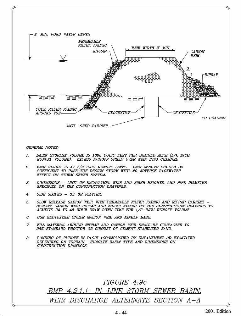


Storm Water Quality Management 4 - 51 2001 EditionGuidance Manual
4.2.1.2 Dry Basin (Off-line Storm Sewer)
The off-line storm sewer dry basin discussed in this subsection is the second of fourdesign options under dry basins.
A. General Design Considerations
The off-line storm sewer basin is defined as a basin used to divert the first flush ofrunoff at some point of the storm sewer system prior to its outfall into a receivingchannel. The majority of runoff flowing in the storm sewer bypasses the off-linestorm sewer basin. The receiving channel may be either man made or a watercourse. Where site area is available, this option provides better water quality control than thein-line storm sewer basin and should be used.
Figure 4.12a, b, and c provide basin configuration and general notes for construction.
The general design considerations of the off-line storm sewer basin should includethe following:
1. The hydraulics of the contributing drainage system must be carefully evaluated tominimize adverse effects of backwater from the basin and discharge mechanism.The design of the basin should not conflict with the storm sewer design criteria asdescribed below:a. The storm sewer should be sized to current design criteria as adopted by the
applicable agency.b. The storm sewer must be able to convey the design flow based on current
criteria as adopted by the applicable agency.2. Computations of the weir in a flow splitter box (see Figure 4.12b) should
consider head loss associated with submerged conditions in the hydraulicanalysis.
3. The basin configuration should be such that the first flush is captured and held forrelease slowly over a 24 to 48 hour period while the remainder of the floodhydrograph may pass through the basin. The draw down time should becontrolled by the riser. See Section 4.2.1.1 for design detail.
4. While no restriction is given for size of drainage area, a 10-acre minimum isrecommended. Larger drainage areas allow more efficient land use for the basin,as described in section 4.2.1.
B. Design Examples
Figure 4.12a, b, and c provide basin configuration and general notes for construction.
Based on Figures 4.12a, b, and c, an example basin design was developed as follows.
The example considers a 50-acre site with storm sewer drainage to a basin. The basinis located at some point upstream of a receiving channel. The first 0.5 inch of runoffis stored in the basin; excess runoff is discharged through a weir in a flow splitterbox. The first flush of runoff is drained through a riser drain to the channel. Theriser drain could optionally reconnect with the storm sewer at some lower elevation.
The purpose of this design is to illustrate how the storm sewer inlet can be located atsome point lower than the half-inch runoff level in the basin. Therefore, the inlet willbe submerged for some time following a storm until the basin drains to a level below

Storm Water Quality Management 4 - 52 2001 EditionGuidance Manual
the invert. This could allow sediments to build up in the inlet pipe. This designassumes that a maintenance program will be in place to keep the inlet pipe clear ofsediments, possibly through periodic flushing. Maintenance costs for keeping thestorm sewer inlet pipe would presumably be higher than for the case where the stormsewer invert is at or above the half-inch runoff level in the basin.
1. Design of Flow Splitter Box Based on 10-Year StormOne design of the flow splitter box weir assumed a 50-acre drainage area, 10-yearstorm event, a 3 foot high sharp crested weir 10 feet long, and a 2.5 footcalculated head over the weir. The basin bottom elevation was assumed to be thesame as the storm sewer inlet invert. Therefore, the effective depth was 5 feet. The off-line basin bottom has a calculated length to width (L:W) ratio of227':113'. The side slopes assumed a 4:1 horizontal to vertical (H:V) ratio. Basindepth from ground surface was 12 feet. Total area required for the basin was1.55-acres and represents 3.1% of the total drainage area, not includingmaintenance berms or access.
2. Design of Flow Splitter Box Based on 3-Year StormAnother design of the flow splitter box weir made the same assumptions asabove, but used a 3-year storm event to determine the length of weir. The weirlength in this case reduced to 7.5 feet. Basin depth and total area required for thebasin remained the same at 12 feet depth and 1.55-acres, not includingmaintenance berms or access.
Sources: Turner Collie & Braden, Association of Consulting Municipal Engineers, LowerColorado River Authority.


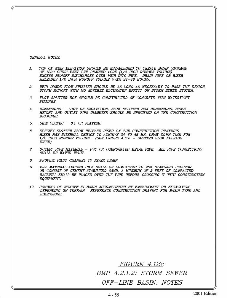

Storm Water Quality Management 4 - 56 2001 EditionGuidance Manual
4.2.1.3 In-line Channel Basin
The in-line storm sewer dry basin discussed in this subsection is the third of four designoptions under dry basins.
A. General Design Considerations
The in-line channel basin is defined as a basin constructed in the main flow stream ofa man made drainage channel.
The application for the in-line channel basin is intended for larger drainage areas butmay be used in any situation where it is cost effective and meets the objectives ofwater quality enhancement. This design may be feasible where a new channel isconstructed. It is not intended that this solution be applied to an existing watercourse. The detention should occur before the runoff enters a watercourse and next to a dropstructure.
Figures 4.13a and b provide basin plan and profile information and general notes forconstruction.
General design considerations of the in-line channel basin include:
1. The in-line channel concept requires approval of HCFCD to ensure that the floodcontrol function of the channel is not impeded. This type of basin is applicableonly in the upper reaches of the watershed.
2. Provision for access to the channel for maintenance should be made.3. Basin storage volume should be 1800 cubic feet per drained acre, which is equal
to the 0.5 inch runoff volume. The basin storage volume should not include anystorage in the channel itself, since the purpose of the channel is conveyance, notimpoundment of water.
4. The basin should drain over a 24 to 48 hour period. The draw down time shouldbe controlled by the riser. See Section 4.2.1.1 for design detail.
B. Design Example
Figures 4.13a and b provide basin plan and profile information and general notes forconstruction.
Based on Figures 4.13a and b, the following illustrative basin was developed.
A drainage area of 100-acres and basin effective depth of two feet provided a basinbottom area of almost two acres. This area's basin bottom has a calculated length towidth ratio of 412':206'. The side slopes assumed a 4:1 horizontal to vertical (H:V)ratio. Assuming a channel depth of 14 feet, total area required for the basin was 3.83-acres and represents 3.83% of the total drainage area, not including maintenanceberms or access.
For illustration purposes, a 10-year storm was used in weir calculation. However, thebasin design should not conflict with the HCFCD requirements for flood controlpurposes. The 10-year storm event generated a peak flow of 249 cfs. For this flowand a one foot head height above the weir, the weir length required was 96 feet. Computer backwater analysis would be required to determine the extent of backwatereffects from the weir, and how much widening of the channel would be neededupstream of the basin, to reduce backwater effects.


Storm Water Quality Management 4 - 59 2001 EditionGuidance Manual
4.2.1.4 Off-line Channel Basin
The off-line channel dry basin discussed in this subsection is the last of four designoptions under dry basins.
A. General Design Considerations
The off-line channel basin is defined as a basin constructed on the side of a manmade channel designed to divert the first flush of runoff. This concept may befeasible where a new channel is constructed. The basin is not intended as a diversionon a watercourse. The application is intended for larger areas but may be used in anysituation where it is cost effective. The off-line concept provides a water qualitybasin separated from the channel, and hence better protection for settled sedimentsthan an in-line concept.
The off-line channel basin concept can also be adapted for use with a storm sewerinlet and a channel outlet. Either a box flow splitter (see Figure 4.12a, b, c) or adiversion dam (see Figure 4.14a, b) could be used to divert the first flush of runoffinto the basin.
Design considerations for the off line channel system should include:
1. The off-line channel concept requires approval of HCFCD to ensure that theflood control function of the channel is not impeded.
2. Provision for access to the channel for maintenance should be made.3. Basin storage volume should be 1800 cubic feet per drained acre, which is equal
to the 0.5 inch runoff volume. The basin storage volume should not include anystorage in the channel itself, since the purpose of the channel is conveyance, notimpoundment of water.
4. The basin should drain over a 24 to 48 hour period. The draw down time shouldbe controlled by the riser. See Section 4.2.1.1 for design detail.
B. Design Examples
Figures 4.14a and b provide basin plan and profile information and general notes forconstruction.
An example design is given as follows, based on Figure 4.14a and b.
The example considers a 100-acre site with open channel drainage to a basin. Adiversion dam in the channel diverts runoff up to the 1/2" runoff level into the basin.When the basin is full, additional runoff spills over the dam and continues down thechannel. The first flush of runoff drains through a riser drain to a lower point in thechannel. The example shows a basin located next to a drop structure, to takeadvantage of a channel elevation change to create a deeper basin than might bepossible otherwise.
A drainage area of 100-acres and basin effective depth of two feet provided a basinbottom area of almost two acres. This area's basin bottom has a calculated length towidth ratio of 412':206'. The side slopes assumed a 4:1 horizontal to vertical (H:V)ratio. Assuming a channel depth of fourteen feet, total area required for the basin was3.83-acres and represents 3.83% of the total drainage area, not including maintenanceberms or access.

Storm Water Quality Management 4 - 60 2001 EditionGuidance Manual
For illustration purposes, a 10-year storm was used in weir calculation. However, thebasin design should not conflict with the HCFCD requirements for flood controlpurposes. The 10-year storm event generated a peak flow of 249 cfs. For this flowand a one foot head height above the diversion dam/weir, the weir length requiredwas 96 feet. Computer backwater analysis would be required to determine the extentof backwater effects from the diversion dam, and how much widening of the channelwould be needed upstream of the diversion dam, to reduce backwater effects.

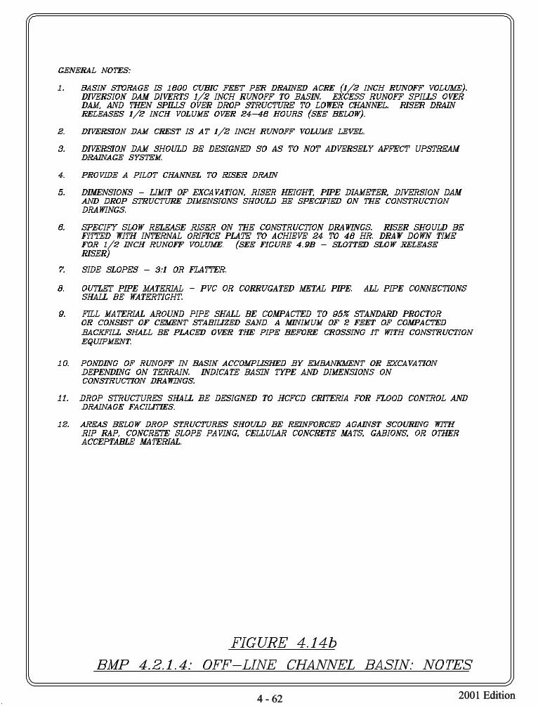

Storm Water Quality Management 4 - 63 2001 EditionGuidance Manual
4.2.2 Wet Ponds
A. Definition
A wet pond has a permanent pool to capture and treat the design storm water runofffrom the drainage area. This system could function either on-line or off-line to thestorm sewer system. The pond could be designed for storm water discharge control,with extra capacity to temporarily detain storm water runoff for later release. Wetponds with extended detention storage above the permanent pool enhance pollutantremoval and reduce downstream bank erosion.
The volume of the permanent pool of a wet pond is referred as water quality volumeor capture volume. It is the volume of storm water runoff captured during theduration of the storm and treated for water quality enhancement through quiescentsettling and biological uptake.
B. Purpose
Wet ponds accomplish two things. During a storm, polluted runoff enters the pondand displaces the existing “cleaner” water in the permanent pond. The displacementof treated storm water reduces the pollutant concentration of the outflow.
Suspended solids in the pond will have a relatively long period of time to settle outuntil the next storm occurs. In addition to efficient settling, this long detention timealso allows removal of dissolved nutrients through biological uptake.
C. Planning Considerations
The wet pond is one of the more reliable and attractive BMPs, with relatively higherpollutant removal efficiency than dry basins, and multiple benefits and amenities. Italso requires careful design, engineering, construction and maintenance.
1. The permanent pool should be designed to hold and treat the design runoff forwater quality enhancements. The permanent pool should remain full at all timesto provide a source of water for wetland plants and minimize resuspension ofsediments. The degree of pollutant removal is a function of pool size in relationto contributing area. The permanent pool should be sized to store 1/2" of runofffrom the contributing drainage area, which is equal to volume of 1800 cubic feetper drained acre. Pond water depth should be no greater than 8 feet to preventthermal stratification. Basins with variable depths that contain both shallow areasof less than 2 feet and deeper areas of greater than 4 feet may be most beneficialfor water quality improvements. The shallow areas can promote growth ofvegetation that enhances nutrient and storm water pollutant uptake and the deeperareas can provide pollutant removal by gravitational settling of solids.
2. The inlet to the permanent pond may be an open channel or a storm sewer. If astorm sewer inlet is used, the storm sewer may use a drop structure or manhole tosubmerge the open end of the pipe. The advantages of a submerged pipe endinclude lack of visual impact and reduced pond bank erosion. The maindisadvantage of a submerged pipe end is the possible need for periodic inspectionand cleaning to prevent sediment build up in the submerged portion of the pipe. The problem of sediment build up can be reduced by minimizing the length ofpipe that is submerged.

Storm Water Quality Management 4 - 64 2001 EditionGuidance Manual
3. Excess runoff may be discharged using a weir, riser or pipe. Riser options aregiven in Figure 4.16b. A brief discussion follows on these riser options.Option A: Overflow Riser. This riser was introduced in Figure 4.11b as part of a
tandem riser concept. Excess runoff discharges through a hoodedopen pipe.
Option B: Negatively Sloped Pipe from Riser. This design was developed toallow for extended detention in wet ponds. The release rate isgoverned by the orifice of the pipe. The risk of clogging is largelyeliminated by locating the opening of the pipe at least one foot belowthe water surface where it is well away from floatable debris. Also,the negative slope of the pipe reduces the chance that debris will bepulled into the opening by suction. As a final defense againstclogging, the orifice can be protected by wire mesh.
Option C: Hooded Riser. In this design, the extended detention orifice is locatedon the face of the riser near the top of the permanent pool elevation. The orifice is protected by wire mesh and a hood, which preventsfloatable debris from clogging the orifice.
4. Studies to date indicate that for most residential developments, pond sedimentsmeet sludge toxicity limits and can be safely landfilled (MWCOG 1992). However, it is the owner's responsibility to test and to properly dispose thesediment.
5. The basin should be designed to facilitate sediment removal. Inspection andmaintenance access should be provided.
D. Design Considerations
Two design options are given in Figures 4.15a and b, and Figures 4.16a, b and c:
Figures Description4.15a, b Wet Pond, In-Line Design4.16a, b In-Line Grass Swales, Wet Pond (Permanent Pool)
The figures provide basin plan and profile information and general notes forconstruction.
General design considerations include the following:
1. The engineer/developer should adhere to all applicable federal, State, and localrules regarding the impoundment of water.
2. The pond and storm sewer must be designed to assure some flushing of sedimentsfrom the pipe to minimize blockages.
3. Provision may be necessary to avoid debris from littering the pond.4. An outlet structure for runoff greater than 0.5 inch should be provided. This
could be in the form of a riser, weir, culverts, or other facility. The design mustnot impact the hydraulics of the upstream storm sewer or channel system underdesign conditions.
5. The areas below the inlet and outlet should be reinforced against scouring withstone, concrete or other lining.

Storm Water Quality Management 4 - 65 2001 EditionGuidance Manual
6. A soil study and geotechnical analysis should be conducted to determineappropriate design for the basin, including measures against piping orgroundwater seepage.
7. The minimum length-to-width ratio of the pond dimensions should be 3:1 toprevent short-circuiting. If a long, narrow pond is not possible, baffles or gabionscan be placed within the pond to control the flow path.
8. Average pond water depth between 3 to 6 feet is recommended, and pond waterdepth should not exceed 8 feet to avoid stratification.
9. Native vegetation capable of thriving under the conditions of the wet pond shouldbe planted. An assortment of vegetation should be planted to survive in thevaried depths of the wet pond. For a partial list of vegetation, see Appendix E. For the permanent pool, species should be selected from the open water/deepmarsh list and the shallow emergent marsh list.
10. The need for an emergency spillway should be evaluated.
E. Design Examples
Figures 4.15a and b, and Figures 4.16a, b, and c, provide basin plan and profileinformation and general notes for construction.
Figures 4.15a, b - Wet Pond - In-Line Design
The example based on Figures 4.15a, b considers a 50-acre site with storm sewerdrainage to a permanent pool. The pool is located next to an open channel. The poolcapacity is one-half inch of runoff. Runoff entering the pool mixes with the poolwater and excess water is discharged through a pipe at the far end of the pool.
A drainage area of 50-acres and basin effective depth of three feet provided a basinbottom area of 0.43-acres. This area's basin bottom has a calculated length to width(L:W) ratio of 238':79'. The side slopes assumed a 3:1 (H:V) ratio for the first twofeet of the bottom and a 10:1 (H:V) for the remaining one foot height. Two 3'X5' boxculverts provided the inlet. Total depth from the pipe invert/basin bottom to theground surface was twelve feet. Total area required for the basin was 1.5-acres andrepresents 3.0% of the total drainage area, not including maintenance berms oraccess.
Outlet was provided with a storm sewer pipe of equal or greater diameter than theinlet storm sewer pipe. Alternately, a weir could be provided for the outlet. Forillustration purposes, a 10-year storm was used in weir calculation. However, thebasin design should not conflict with the HCFCD requirements for flood controlpurposes. The 10-year storm event generated a peak flow of 138 cubic feet persecond (cfs). For this flow and a one foot head height above the weir, the weir lengthrequired would be 53 feet.
Figures 4.16a, b, c - In-Line Grass Swales, Wet Pond Permanent Pool
The example based on Figures 4.16a, b and c applies to smaller sites with a minimumarea of 10 acres. In this example, storm water is collected by grass swales andconveyed through storm sewers into a permanent pool. The example illustrates theuse of grass swales for the dual purpose of landscaping and vegetative filtration.

Storm Water Quality Management 4 - 66 2001 EditionGuidance Manual
A drainage area of 10-acres and basin effective depth of three feet provided a basinbottom area of 0.08-acres. This area's basin bottom has a calculated length to widthratio of 124':41'. The side slopes assumed a 3:1 horizontal to vertical (H:V) ratio. Depth from the pipe invert to ground surface was seven feet giving a total depth tothe basin bottom of 7.5 feet. Total area required for the basin was 0.33-acre andrepresents 3.3% of the total drainage area, not including maintenance berms oraccess.
The grass swales were 8 feet wide with a 4:1 side slope, and 0.1% minimum slope,and required 0.48 acre of site area. The area dedicated to the storm water qualitysystem (basin and swales), at 8.1%, is consequently more than double the area neededif only grated inlets were used for storm water collection (3.3%). These figures donot include maintenance and access area.
F. Maintenance
1. Maintenance and inspection access to the facility should be provided.2. Sediment should be removed from the pond area when accumulations exceed
one-third the design depth of the pond.3. Accumulated paper, trash and debris should be removed every 6 months or as
necessary.4. The side-slope, embankments and spillway areas should be mowed at least twice
a year to discourage woody growth and control weeds.5. A visual check inspection should be conducted after each rainfall event of 1 inch
or more in 24 hours until the pond and drainage system are stabilized. Thereafter,visual checks should be conducted as needed to inspect for damage and anynecessary repairs.
6. It is recommended that a complete inspection be conducted at least annually.
Sources: Turner Collie & Braden, Lower Colorado River Authority, Metropolitan WashingtonCouncil of Governments 1987, Metropolitan Washington Council of Governments,1992, Minnesota Pollution Control Agency.


Storm Water Quality Management 4 - 71 2001 EditionGuidance Manual
4.2.3 Dual Use Flood Control/Water Quality Basin
A. Definition
The dual use basin is a flood control structure that also provides water qualityenhancement. The basin has three storage stages, a permanent pool, an extendeddetention, and a flood control volume. The permanent pool and the extendeddetention areas of the basins serve the primary function of water qualityenhancements.
The volume of the permanent pool is referred as water quality volume or capturevolume. It is the volume of storm water runoff captured during the duration of thestorm and treated for water quality enhancement through quiescent settling andbiological uptake.
B. Purpose
The dual use basin is intended to provide storm water quality and quantity controlfunctions in a single facility. The dual use approach may apply to a new basin or anexisting flood control structure retrofitted for water quality enhancements.
The permanent pool of the basin captures and treats the design runoff. Extendeddetention storage is provided above the permanent pool. The extended detentionenhances settling of total suspended solids and prevents downstream channel erosionby abating downstream channel velocities. This volume is stored and released over a24 to 48 hour period. The flood control volume protects downstream flooding fromhigher magnitude events such as the 100-year storm flood.
C. Planning Considerations
This basin may be provided anywhere along the storm sewer or channel systemwhere hydraulics permit. A key advantage to the dual use basin relative to otherwater quality basins is efficient land use. A possible disadvantage is increasedmaintenance requirements over the single-use flood control detention basin due towater quality functions. The basin should be designed to facilitate sediment removal.Inspection and maintenance access should be provided.
D. Design Considerations
Figure 4.17 provides basin plan and profile information and general notes forconstruction. The water quality volume storage is 0.5 inch of runoff from thedrainage area. When a storm begins, the first flush of runoff is captured and treatedin the permanent pool. The extended storage provides additional water qualitybenefits and downstream channel protection, and is usually defined as the volume ofan additional 0.5 inch of runoff.
Design considerations of the dual use pond include the following:
1. The water quality portion of the basin must be sized to store the first flush (first0.5 inch of runoff). This is equal to 1800 cubic feet of storage per drained acre. The permanent pool should remain full at all times to provide a source of waterfor wetland plants and minimize resuspension of sediments.
2. The depth of the permanent pool should not exceed 8 feet to prevent thermalstratification. Pools less than 2 feet without aquatic vegetation are also prone to

Storm Water Quality Management 4 - 72 2001 EditionGuidance Manual
resuspension problems. Basins with variable depths that contain both shallowareas of less than 2 feet and deeper areas of greater than 4 feet may be mostbeneficial to water quality improvements.
3. The shallow areas of the permanent pool promote growth of emergent aquaticvegetation that enhance nutrient uptake. The deeper pool area provides pollutantremoval by gravitational settling. An aquatic shelf with depths less than 18inches should surround the permanent pool.
4. The permanent pool volume cannot be considered for flood control purposes. The overall design should not impact the water surface elevations of upstreamdrainage systems, or the routing of the design flood hydrograph.
5. The extended storage should be released within 24 to 48 hours. The slow releaseshould be controlled by the riser design as discussed in Section 4.2.1.1 or anyother appropriate outlet control structure.
6. The extended storage and the flood storage stages of the basin should be designedto meet the HCFCD drainage criteria for detention basins.
7. Native vegetation capable of thriving under the conditions of the wet pond shouldbe planted. An assortment of vegetation should be planted to survive in thevaried depths of the wet pond. For a partial list of vegetation see Appendix E. For the permanent pool, species should be selected from the open water/deepmarsh list and the shallow emergent marsh list.
E. Design Examples
Figures 4.17 and 4.18 provide basin plan and profile information, and general notesfor construction.
A drainage area of 50-acres and basin effective depth of two feet provided a basinbottom area of almost one acre. The side slopes assumed a 4:1 horizontal to vertical(H:V) ratio.
The volume of the permanent pool sized to capture the first half inch of runoff fromthe drainage area (50 acres) is 90,000 cubic feet.
The basin design for the extended storage and flood control volume must follow theHCFCD requirements. Hydrologic and hydraulic modeling is required to size theflood control storage volume and the outlet devices. The designer should refer to theHCFCD drainage criteria manual and meet the requirements of HCFCD.
F. Maintenance
1. Maintenance and inspection access to the basins should be provided.2. Sediment should be removed from pond or reservoir areas when accumulations
exceed one-third the design depth of the pond or reservoir.3. Accumulated paper, trash and debris should be removed every 6 months or as
necessary.4. The vegetation should be mowed at least twice a year to discourage woody
growth and control weeds.5. A visual check inspection should be conducted after each rainfall event of 1 inch
or more in 24 hours until the pond and drainage system are stabilized. Thereafter,
Storm Water Quality Management 4 - 73 2001 EditionGuidance Manual
visual checks should be conducted as needed to inspect for damage and anynecessary repairs.
6. It is recommended that a complete inspection be conducted at least annually.7. Standing water above the surface of the permanent pool left after 72 hours
indicates clogging of drain pipes or drainageways, and need for inspection andmaintenance. Provisions should be made for occasional dewatering as necessaryfor maintenance work and to control nuisances which may arise.
Sources: Turner Collie & Braden, Lower Colorado River Authority, Metropolitan WashingtonCouncil of Governments 1987.


Storm Water Quality Management 4 - 76 2001 EditionGuidance Manual
4.2.4 Constructed Wetlands
A. Definition
Storm water wetlands are constructed facilities designed often based on theecological function of natural wetlands for storm water treatment purposes. Wetlandtreatment of storm water runoff involves passing runoff through a constructedwetland for providing water quality improvement by removing pollutants.
B. Purpose
Wetland treatment is effective in removing sediment and pollutants that bind toparticles, such as heavy metals, nutrients, and hydrocarbons. Wetlands also removeoxygen demanding substances and bacteria. Wetlands can also be effective inremoving dissolved nutrients.
Wetlands utilize pollutant removal mechanisms similar to wet ponds, but emphasizethe biological processes of wetland habitats. Thus, wetlands are highly effective butsensitive, and can be damaged by pollutant overloads. Features such as sedimentforebays can be designed to enhance the pollutant removal capabilities of constructedwetlands. Generally, pollutant removal efficiency increases with a larger ratio ofwetland to watershed size. Larger size ratios increase hydraulic residence time andbiological processing.
C. Planning Considerations
Because of their shallow depths typically less than 2 feet, wetlands require more landarea than other treatment BMPs. Constructed wetlands can be considered for largedevelopments. They can be used in watersheds as small as 5 acres. Constructedwetland basins should be designed to facilitate inspection and maintenance. Maintenance access should be provided.
Wetlands can provide an excellent urban habitat for wildlife and waterfowl,particularly if they are surrounded by a buffer and have some deeper water area. Inmost cases, storm water detention can be provided in constructed wetlands, allowingdual use of the wetlands.
Requirements for Section 404 permits should be evaluated on a case-by-case basis. Modification of an existing wetland area to serve a storm water quality managementfunction is potentially subject to Section 404 permitting. Newly constructedwetlands, should be evaluated for the exemption listed in 40 CFR 122.2. It providesan exemption to classification as “Waters of the U.S.” for waste treatment pondsystems or lagoons, designed to meet the requirements of the Clean Water Act. However, if a constructed wetland is exempted by being defined as a treatmentfacility, it cannot be used for wetlands mitigation for losses due to construction. Modification and ongoing maintenance of an exempt constructed wetland would alsobe exempt from permitting requirements.
Wetland treatment, however, requires a water budget analysis and careful design. Wetland treatment requires relatively large land area compared with other waterquality basins. Careful selection of diversified wetland plant species is one of themost important planning aspects to avoid takeover of the wetlands system by invasiveaquatic nuisance plants. There are possible impacts on wetland biota from heavy

Storm Water Quality Management 4 - 77 2001 EditionGuidance Manual
metal uptake and bacterial contamination from waterfowl.
D. Design Considerations
Figures 4.19a and 4.19b provide basin plan information and general notes forconstruction.
The following criteria are recommended for constructed wetlands.
1. As a general guideline, no more than 25 percent of the wetland should be openwater, with depths between 2-3 feet. The remaining area should be heavilyvegetated, with depth less than 1 foot. However, a wetland specialist should beconsulted for application to a specific location.
2. The inlet should open onto a forebay for settling larger solids. The forebayshould be deep enough for slowing down the flow velocity.
3. An oil/water separator (for example, the SC type separator, discussed in Section4.4.2) may be needed preceding the inlet to minimize any oil and grease impacton vegetation.
4. The wetland perimeter should have a vegetated buffer 10-20 feet wide that istemporarily flooded in most storm events.
5. Soils in the pool area should be wetland soils, containing a large number ofwetland plant propagules. A soil study and geotechnical analysis should beconducted. Soils through the wetland should have a minimum depth of fourinches, and an infiltration rate low enough to maintain a permanent pond.
6. The landscaping plan should be carefully designed for wetland habitat, usingindigenous species to the maximum extent practicable. See Appendix E for listsof open water/deep marsh vegetation, shallow emergent marsh vegetation,wet/mesic prairie vegetation, dry prairie grasses, wildflowers, trees, and shrubs.
7. A plant management plan needs to be developed by a qualified wetland biologistor professional.
E. Design Example
The example based on Figure 4.19 considers a 100-acre site with a wetland basin. The wetland functions as a shallow permanent pool. Incoming runoff displaces theexisting water in the basin. The wetland has an average depth of 1 foot or less, with25% of the area between 2-3 feet, 25% between 0.5-1 foot and 50% at 0.5 foot depth.The example assumes a shallow inlet with an SC (Spill Control) Oil/Water Separator.
The basin area of 4.5 acres includes the submerged area and the 10 to 20-footfrequently flooded fringe, but does not include maintenance or access.
A riser outlet is shown in Figure 4.19a, but a suitably designed weir or pipe couldalso be used for the outlet.
F. Maintenance
1. Maintenance and inspection access should be provided to the wetland.2. Oil/water separators preceding the inlet, if required, should be cleaned at least
twice a year.3. If the vegetation will be harvested, design features should be included for

Storm Water Quality Management 4 - 78 2001 EditionGuidance Manual
dewatering. The harvesting procedures must be prepared by a qualifiedprofessional, and should be reviewed and approved by the agencies withjurisdiction.
4. A visual check inspection should be conducted after each rainfall event of 1 inchor more in 24 hours until the basin and drainage system are stabilized. Thereafter, visual checks should be conducted as needed to inspect for damageand any necessary repairs.
5. It is recommended that a complete inspection be conducted at least annually.
Sources: Metropolitan Washington Council of Governments 1987, Metropolitan WashingtonCouncil of Governments 1992, Minnesota Pollution Control Agency, WashingtonState Department of Ecology.

Shallow marshDeep marsh/plunge pool 3 - 4’ deep
Vegetation spillway, 6” deep
Wet prairie
Dry prairie
Varying water depths for wetland marsh shelves
Marsh with varying water depth4-16 inches
Outlet
Shallowmarsh
Island
HP
HP
Micro pool
HP
HP
Meandering low flow channel
6” deep low-flow weir/spillway withnative grass planting
Plunge pool, 3 - 6’ deep2:1 length to width ratio
Inlet channel
Debris/oil trap(bulrush stand)
Shallow marsh
Deep marsh
Plunge pool
Debris/oil trap(bulrush stand)
Inlet
Deep marsh
Shallow marsh
Utilize cut material from micro pool andchannel excavation to create high points.Maximize the length of low-flow channel toprovided maximum treatment.Maximize ecological benefits through maximizedwater to vegetation edge and interface.
HP
HP
Shallowmarsh
Deep marsh
Wet prairie
Canopy trees
Shrub mass
Hp High point
NWL: Normal Water Level - Level of Water Quality VolumeHWL: High Water Level - Extended detention Volume
BMP 4.2.4: POTENTIAL WETLAND FIGURE 4.19a
4 - 79
POTENTIAL WETLAND DESIGN
LWL
Riprap apronSediment trapand plunge pool
6"-8" Riprap apron swaleLow flow meandering channel
6"-8" Riprap
4:1
3' deep (typ.)4:1
Wetprairie
Shallowmarsh Deep marsh Micro pool (4-6’)
Schematic Cross-section of Water Quality Treatment WetlandNot to Scale
(0-18”) (18-30”)
Riser outlet
Discharge
N WL
HWL
Marsh
Meanderingchannel
High pointHigh point Shallow and deep marsh
2001 Edition


Storm Water Quality Management 4 - 81 2001 EditionGuidance Manual
4.3 Infiltration/Filtration Facilities
Infiltration and filtration practices filter storm water through soil, sand or other mediawhich attach to particulates and allow biological processing. Infiltration practices allowstorm water to recharge into the soil, and have no underdrain system. Filtration practicesuse an underdrain system beneath the filter medium to collect and discharge the filteredstorm water.
In general, infiltration facilities require permeable soils, and are sensitive to clogging,making them impractical in the Houston/Harris County region, which is typified by soilswith fine clays and low permeability. For this reason, infiltration measures such asinfiltration basins, infiltration trenches, porous pavement and grid/modular pavement willnot be thoroughly discussed in this Manual. Infiltration practices may be useful in theHouston/Harris County region if they are employed as part of Low Impact Development(LID) site design. See Section 4.6 of this Manual for a discussion of LID. The interestedreader may refer to the following sources (among others) for more information oninfiltration practices:
Washington State Department of Ecology (WSDOE)Metropolitan Washington Council of Governments (MWCOG)Florida Department of Environmental Regulation (Florida DER)
Filtration facilities are sensitive to clogging, but not to the extent of infiltration facilities.The sand filter is a popular type of filtration facility, and may be used in conjunction witha water quality dry detention basin for enhanced pollutant removal. (See Section 4.2.1 -Dry Detention Basins). Filtration facilities require some amount of topographic relief toprovide adequate hydraulic head for detention and filtration. Therefore, their applicationto the Houston/Harris County area, which is characterized by generally flat topography,would tend to be limited. For this reason, filtration measures such as full or partialsedimentation-sand filters, will not be thoroughly discussed in this Manual. Theinterested reader may refer to the following sources (among others) for more informationon filtration practices:
Austin Department of Environmental Protection (Austin DEP)Galli (1990)Metropolitan Washington Council of GovernmentsWashington State Department of Ecology (WSDOE)

Storm Water Quality Management 4 - 82 2001 EditionGuidance Manual
4.4 Catchment Facilities
Two types of underground storm water treatment devices are discussed in this section: catch basins and oil/grit separators. They are typically designed as inlet devices for stormdrains. Catch basins trap coarse sediments and large debris, but are ineffective on oil andgrease. Oil and grit separators have several different designs and different removalcapabilities.
Catch basin (4.4.1)Oil/grit separators (4.4.2)
4.4.1 Catch Basin
A. Definition
Catch basins are chambers or sumps installed in a storm sewer, usually at the curb,which allow surface runoff to enter the sewer.
B. Purpose
Many catch basins have a low area for retaining sediment. By trapping coarsesediment, the catch basin prevents trapped solids from clogging the sewer or beingwashed into receiving waters.
C. Planning Consideration, Design Criteria and Maintenance
Refer to Figure 4.20. Catch basins are typically part of storm sewer design. Inspection and cleaning should be included in the storm sewer life cycle costs. Dueto low pollutant removal ability, and possible nuisances (mosquitoes, odors), catchbasins should not be considered as stand-alone structural controls, but may be used inconjunction with other controls, including non-structural controls (see Section 4.1).
The grit chambers in most catch basins have a capacity of 0.5 to 1.5 cubic yards. Therate at which catch basins fill is variable, depending on the surrounding land uses andconstruction activity.
Cleaning should be done on a semi-annual basis and more frequently for areas withactive construction.
Source: Pitt, Minnesota Pollution Control Agency.


Storm Water Quality Management 4 - 84 2001 EditionGuidance Manual
4.4.2 Oil/Grit Separators
A. Definition
Oil/grit separators (also called water quality inlets) are inlet devices for separating oiland sediments from water.
B. Purpose
Oil/grit separators have chambers designed to remove sediment and hydrocarbonsfrom urban runoff. They are normally used close to the source before pollutants areconveyed to storm sewers or other BMPs such as infiltration trenches. Oil/gritseparators are typically used in areas with heavy traffic or high potential forpetroleum spills such as parking lots, gas stations, roads, and loading areas.
There are three general types of separators. The simple spill control (SC) separator(Figure 4.21), typically required with storm water quantity detention facilities, iseffective at retaining only small spills. It will not remove diluted oil droplets spreadthrough the storm water from oil contaminated pavement.
More sophisticated designs used for high load situations such as fueling stations,parking lots, and industrial plants include the American Petroleum Institute (API)Figure 4.22, Coalescing Plate Interceptor (CPI) Figure 4.23, and Municipality ofMetropolitan Seattle designs. The API design uses a basin with baffles to improvehydraulic conditions for settling solids and floating oil. The CPI design improvescoalescing and settling by directing the runoff through closely positioned parallelplates set at an angle. Removal efficiencies of the CPI separator are similar to thoseof the API separator, but the CPI separator uses 50% to 80% less space. However,both the API and CPI type separators have limited ability to handle storm water flowsand hydrocarbon concentration, which are much lower than refinery wastewater. Thedesign used by Municipality of Metropolitan Seattle uses layers of corrugatedcoalescing plates oriented at 90° to each other.
Performance of oil/grit separators can be enhanced using adsorbent pillows or similarmaterial. Used adsorbent pillows must be properly disposed.
C. Planning Considerations
Oil/grit separators are restricted to small, highly impervious drainage area of twoacres or less, and must connect to the storm drainpipe. Suitable locations include gasstations, convenience stores, parking lots, fast food restaurants, industrial loadingfacilities, and sections of industrial plants.
Separators show some capability to remove coarse sediments (trash, debris andfloatables), and oil and grease. However, the overall removal capability is low. Oil/grit separators should only be considered as a primary BMP when properly sizedand combined with a program of frequent inspection and maintenance.
While they are highly adaptable, oil/grit separators are relatively expensive to installand potentially expensive to maintain. The greatest concern is the pollutant toxicityof trapped residuals and oily waters, and their disposal. A secondary concern is thepossibility of flushing of trapped residuals during longer or larger storms. A well-implemented inspection and maintenance program will ameliorate these potentialconcerns.

Storm Water Quality Management 4 - 85 2001 EditionGuidance Manual
D. Design Criteria
1. In order to provide at least moderate sediment, oil and grease pollutant removal,oil/grit separators should be of the API-type (Figure 4.22) or CPS-type (Figure4.23) sized to capture 90-micron particles, or an equivalent. Proprietary productsare commercially available and may be used if performance is equivalent orbetter.
2. The oil/grit separator should be an off-line design, capturing only the first flush ofrunoff. The unit should not interfere with the normal storm sewer function. (Inthe Municipality of Metropolitan Seattle design, the first flush is based in part ona discharge rate for the design storm of about 1,000 gpm (2.23 cfs) for a 1,500 cfcapacity oil/grit separator, giving a hydraulic residence time of 11 minutes.)
3. The API-type separator will typically have three chambers. Runoff enters thefirst chamber, which contains a permanent pool of water. Coarse sediment istrapped in this chamber by settling. The first chamber can also trap floating trashand debris such as leaves.Runoff then passes through an orifice to the second chamber which also containsa permanent pool of water. An inverted pipe elbow which draws water from thelower part of the pool discharges to the third chamber. By drawing water frombelow the surface, floating oil and grease are trapped until they are adsorbed tosediment particles which then settle out.The third chamber discharges water to a storm sewer or other outlet. If the stormdrain invert is above the floor of the structure, a permanent pool of water will beformed which will allow some additional settling. If the storm drain invert is atthe floor of the oil/grit separator, the third chamber would have no value inpollutant removal.In order for the structure to provide even moderate pollutant removal benefits, atleast 400 cubic feet of permanent pool storage should be provided per acre ofdrainage area. Also, the pool should be at least four feet deep.
4. Manholes should be provided to each chamber to provide access for cleaning.Manholes should be accessible to cleaning equipment.
E. Maintenance
1. The facility should be checked weekly by the owner.2. The facility should be completely inspected and cleaned out at least twice a year
to maintain the pollutant removal capabilities.3. Sediment should be cleaned out with a vacuum truck.4. Oil adsorbent pads, if used, are to be replaced as needed but should always be
replaced after cleaning.5. The effluent shutoff valve is to be closed during cleaning operations.6. Waste oil and residuals must be disposed in accordance with current TNRCC
and/or Health Department requirements.7. Any standing water removed during the maintenance operation must be disposed
at an approved discharge location.8. Any standing water removed should be replaced with clean water to prevent oil

Storm Water Quality Management 4 - 86 2001 EditionGuidance Manual
carry-over through the outlet weir or orifice.
Sources: Metropolitan Washington Council of Governments 1987, Metropolitan WashingtonCouncil of Governments 1992, Minnesota Pollution Control Agency, WashingtonState Dept. of Ecology, personal communications with Metro staff: B. Burrow, P.Eng, C. Kircher


Storm Water Quality Management 4 - 90 2001 EditionGuidance Manual
4.5 Vegetative Practices
This section discusses practices where the primary element is vegetation, for purposesother than erosion and sediment control. Erosion and sediment controls are discussed ina separate manual (Storm Water Management Handbook for Construction Activities).
Vegetative practices remove pollutants through infiltration and biological uptake. Absentother BMPs such as ponds or filtration trenches, vegetative practices provide at least alow to moderate amount of pollutant removal, while also enhancing the habitat value andaesthetics of a site.
Vegetative practices include:
4.5.1 Grassed swales (grassed waterways)4.5.2 Vegetated filter strips
4.5.1 Grassed Swales
A. Definition
A grassed swale is a constructed drainageway with vegetated lining established bysodding or seeding.
B. Purpose
Grassed swales decrease flows and velocity through retardance and infiltration, thusreducing sediment transport.
C. Design Criteria and Requirements
Refer to Figure 4.24.1. Timing: Vegetation and any protective materials should be installed
immediately after final channel grading.2. Capacity: Grass swales for water quality enhancements should be sized to
treat the flow generated by 0.27 in/hr rainfall intensity from thedrainage area. The maximum water depth should be 3 inches or halfthe grass height whichever is less.
3. Check Dams:Check dams shall be used if site conditions do not allow for achievinga longitudinal slope of 2% or less. They should be reinforced withstone on the downstream side to prevent scouring. Maximumponding time behind the check dams should not exceed 24 hours.
4. Outlets: All grassed swales should have a stable outlet with adequate capacity,and designed and should be built to prevent erosion of channels andbanks.
D. Maintenance
1. Grassed swales should be inspected within 24 hours after each storm of 0.5 inchor greater or daily during periods of prolonged rainfall, until the vegetation isestablished. During the initial establishment period, repairs and replacementsshould be made immediately.
2. After the grass has become established, the swale should be checked at least

Storm Water Quality Management 4 - 91 2001 EditionGuidance Manual
monthly. All repairs or replacement should be made as soon as possible.
Sources: Metropolitan Washington Council of Governments 1987, Metropolitan WashingtonCouncil of Governments 1992, Florida Dept. of Environmental Regulation, AustinDept. of Environmental Protection, and Harris County, Harris County Flood ControlDistrict and City of Houston


Storm Water Quality Management 4 - 93 2001 EditionGuidance Manual
4.5.2 Vegetated Filter Strips
A. Definition
Vegetated filter strips are landscaped strips planted with grass, trees or othervegetation.
B. Purpose
Vegetated filter strips treat overland flow through infiltration and biological uptake ofsediments and particulate pollutants. There is also some removal of organics andtrace metals.
C. Planning Considerations
It is critical that vegetated filter strips be designed and constructed so that runoffflows uniformly across the filter. In order to accomplish this, the filter strip should beconstructed along the entire length of a contributory area and receive the runoff assheet flow. The top edge of the filter should be level. Any depressions willconcentrate runoff and short-circuit the filter. In some cases, a shallow stone trenchcan be used to uniformly distribute runoff at the top of the filter. If a filter has beenused to trap sediment during construction, it may be advisable to regrade and reseedthe top of the filter. Otherwise, sediment accumulations may cause runoff toconcentrate in certain locations.
Refer to Figure 4.25.
D. Design Criteria
1. Flow velocities over the filter strip should not exceed 1 ft/sec. for the designstorm.
2. Slopes should be between 0.1% and 10%.3. The strip should be constructed along the entire length of the contributing area,
and should be a minimum of 20 feet wide.4. A level spreading device (vegetated berm or rock trench) may be used to facilitate
overland sheet flow onto the filter.5. Close growing vegetation is required. The strip should be protected from erosion
until the vegetation is established.
E. Maintenance
1. Maintenance requirements for filter strips can be reduced by managing them asnatural areas where vegetation is not mowed. Otherwise, filters should be mowedregularly and fertilized as needed to maintain the vegetation in a healthycondition.
2. Any small rills that form should be repaired promptly to prevent further erosion. This is critical during the initial establishment period for vegetation, but must bechecked during later inspections, also.
Sources: Metropolitan Washington Council of Governments 1987, Lower Colorado RiverAuthority, Minnesota Pollution Control Agency, and Harris County, Harris CountyFlood Control District and City of Houston


Storm Water Quality Management 4 - 95 2001 EditionGuidance Manual
4.6 Low Impact Development
A. Definition Low Impact Development utilizes site design techniques that store, infiltrate,evaporate, and detain runoff on the site to replicate predevelopment runoffcharacteristics and mimic the natural hydrology of the site.
B. Purpose Low Impact Development combines site designs with pollution prevention measuresto reduce impacts and compensate for development impacts on hydrology and waterquality. The purpose of Low Impact Development is to maintain the predevelopmentpeak storm water runoff and runoff volume, and time of concentration to mimic thepredevelopment hydrology. Storm water is managed in small, cost effectivelandscape features located on each lot rather than being conveyed and managed inlarge facilities located at the end of the drainage system. Compared withconventional end-of-pipe treatment, it emphasizes management of storm water runoffat the source. The paradigm that currently dominates site planning is that storm wateris undesirable and must be removed from the site as quickly as possible to achievegood drainage. The principal goal of low-impact development is to ensure maximumprotection of the ecological integrity of the receiving water by maintaining theexisting hydrologic regime.
Low Impact Development techniques can be used to provide high qualitydevelopment. Low Impact Development provides consolidated spaces to supportwetland plants and wildlife. As such, it provides natural amenities in terms of plantand animal diversity in close proximity to human habitation.
C. Planning Consideration
Planning consideration includes analysis of predevelopment site hydrology andeffective utilization of the existing site features to maintain the predevelopmenthydrologic regime. Site hydrology analysis allows full utilization of the propertywhile maintaining the predevelopment hydrologic regime to the greatest extentpossible. The planning consideration may require rethinking of the current practiceof site development, site grading, and site layout and design. Hydrologic functions ofthe site should be maintained and managed with the use of reduced impervioussurfaces, minimized land clearing and grading.
Low Impact Development techniques alone do not offer flood protection. Additionalflood design criteria should be reviewed to ensure flood protection is provided.
Some specific planning considerations include:
1. Minimizing environmental impacts and hydrologic changes.2. Preserve adequate open space within the development site for bio-retention, and
treatment of runoff from rooftops and other impervious surfaces.
Planning considerations for local governments could also include:
3. Providing economic incentives to utilize low impact development strategies.4. Encouraging public education and support of low impact development.5. Identifying and eliminate conflicting ordinances, codes, and funding mechanisms

Storm Water Quality Management 4 - 96 2001 EditionGuidance Manual
that prevent low impact development.D. Design Guidelines
To reduce development impacts and preserve the predevelopment hydrologicconditions the following could be used as general guidelines. Figures 4.26 to 4.30present sample illustrations of low impact development and conventional site planlayout.
1. Minimize land clearing that requires removal of the native vegetation.2. Minimize or avoid mass grading and utilize selective clearing.3. Reduce impervious surface area and minimize connected impervious surfaces.4. Increase opportunity for on-site retention, detention, and treatment.5. Maintain predevelopment hydrologic pattern.6. Utilize native vegetation.7. Utilize undisturbed existing vegetation buffer strips and areas.8. Whenever site condition permits, utilize extensive use of swales, grass filter
strips, and randomly placed biofilters. Direct roof and landscape open area runoffto vegetated biofilter strips and swales.
9. Preserve soils and areas with high infiltration rate.10. Provide multi-purpose and multi-benefit storm water detention basin onsite.11. Grade the site to maximize the overland sheet flow distance.12. Increase flow-paths or travel distances for surface runoff.13. Maintain existing time of concentration and minimize impact on the runoff
coefficient number.14. Utilize cisterns, rain barrels, bioretention areas, and created seasonal or
permanent wetlands.15. Provide adequate buffers between development and natural resources, critical
areas and drainage ways.16. Lay out roads, utilities, and pervious surfaces to avoid existing wetlands and
drainage paths.17. Handle road runoff separate from roof top and landscape area runoff.18. Integrate low-rise and high-rise buildings, town houses, in single-family
residential to reduce land consumption.

4 - 97
CONVENTIONAL LAND DEVELOPMENT SITE PLAN FIGURE 4.26 a
CONVENTIONAL SITE PLAN
Gap
C
ourt
Fern Way
Deni Loop
Canted Road
Barker Trail
Able Court
Cen
tral
Par
kway
Existing Wetland
Existing Wetland
2001 Edition

MODIFIED CONVENTIONALLAND DEVELOPMENT SITE PLAN FIGURE 4.26b
4 - 98
MODIFIED CONVENTIONAL SITE PLAN
Gap
Court
Fern Way
Deni Loop
Canted Road
Barker Trail
Able Court
Cen
tral
Par
kway
Existing Wetland
Existing Wetland
Direct street drainage to constructed treatment wetland prior to discharge to existing wetland
Maintain adequate undisturbed open space as a buffer aroundexisting wetland
Preserve existing wetland
Drainage corridor50 foot minimum
Drainage and wildlife corridor.Omit selected lots to maintain asundisturbed open space
Pipe under road
Maintain as undisturbed openspace preserving existing drainagepattern and connection between wetllands
Direct roof top runoff andlot runoff to drainage swaleand wildlife corridor
Direct roof top runoff andlot runoff to drainage corridor
Maintain natural undisturbed open spacefor drainage and wildlife corridor
Omit Cul-de-sec and some lots(as shown in Conventional Site Plan)to maintain adequate open space
Buffer undisturbedopen space
Shorten Cul-de-secand 2 lots to maintainadequate buffer
25 footminimum
Drainage off lots directedto corridor (typical)
2001 Edition

LOW IMPACT DEVELOPMENT SITE PLAN FIGURE 4.27a
LOW IMPACT DEVELOPMENT SITE PLAN
4 - 99
Gap Trail
Edge Trail
Deni Loop
Cen
tral
Par
kway
CantedCourt
Able Court
Barker Court
Fer
n W
ay
Fern Loop
Wildlife
Lane
ExistingWetland
4 familylow-risetownhouses
4 familylow-risetownhouses
H.P.
H.P.
5 familylow-risetownhouses
Maintain undisturbed vegetated
Buffer around entire development
Maintain existing drainage pattern andhydrological connection and unbrokenwildlife corridor
Undisturbed vegetated buffer
Utilize high points and natural topographyto guide development plan layout
H.P.
H.P.
5 familylow-risetownhouses
5 familylow-risetownhouses
H.P.
4 familylow-risetownhouses
5 familylow-risetownhouses
Undisturbedvegetated buffer
Pipe
Pipe
15 “Lots” lost from conventional plan37 “Lots” accommodated in low-risetownhouse units for seniors, coupleswith no children, or families with childrenand do not want yard maintenance.
Existing Wetland
2001 Edition


LOW IMPACT DEVELOPMENTWATER QUALITY TREATMENT COMPONENTS FIGURE 4.28a
3' wide trench6' wide side slope
16' wide side slope
Centerline of biofilter swale1640 feet total length
InletRiprap apron spillway
25-foot wide native dry prairie buffer
Shallow marsh wetland
Deep marsh wetland
Deep open water poolDetention
Basin
Discharge toExisting waterwayOverflow weir
Earth embankment
Riprap apron
Sediment trap(2 times length aswidth typical)
25'
Min.15 feet wide
680' length
Min. 25 feet wide
B B
A
A
Schematic Plan: Water Quality Treatment SiteNot to Scale
Inflow from adjacentdevelopment
Riprap spillway
C C
Inflow Cul-de-sac960' length
4 - 101
Sheet drainagefrom adjacentdevelopment
Piped drainage from development
TREATMENT PLAN
NOTE:
PRE-DEVELOPMENTHYDROLOGIC REGIME WILL BEMAINTAINED BY CREATINGMEANDERING FLOW PATHS, ASERIES OF DETENTIONFEATURES WITHIN SWALES,AND AREAS OF NATIVE LUSHPLANT GROWTH TO RETARDFLOWS. SEE FIGURE 4.28b,FIGURE 4.28c, AND FIGURE4.28d.
2001 Edition

FIGURE 4.28c
FIGURE 4.28b
LOW IMPACT DEVELOPMENTWATER QUALITY TREATMENT COMPONENTS
4 - 102
HWL
NWL
LWL
Riprap apronSediment trap
6"-8" Riprap apron spillwayLow flow swale
6"-8" Riprap
4:1
3' deep (typ.)
4:1 0"-18"18"-30"
Wet prairie Shallow marsh Deep marsh
4'-6'
Open water pool
Schematic Cross-section A-A Water Quality Treatment WetlandNot to Scale
Adjustable overflow weir in earth embankment
Discharge to detention basin
NWL
Wet prairiegrasses/forbs
Native dryprairie grasses
Shallow marshwetland plants
Mesic prairiegrasses/forbs
Dry prairiegrasses/forbs
Surface flow from subdivision
1:8 - 1:12 Typicalside slope
Flat bottom
4:1 Typ.
Centerline of biofilter swale
Schematic Cross-section C-C: 15-foot wide Biofilter SwaleNot to Scale
2001 Edition

BIO-FILTER
2001 Edition
16'Native prairie grass & forbs Infiltration trench
(sized for 2" rainfall)
3' 6'
4:1 Side slope
18"-26"
4"-6" Min. Cover
8"-12"
6"-8"
Centerline of swale
Sand
1"-3" Size gravel
Filter cloth4"-6" Soil backfill
12:1-8:1 Side slope
Perforated pipe(size to be determined)
Native prairiegrass & forbs
Schematic Cross-section B-B:25-foot wide Biofilter Swale
Not to Scale
LOW IMPACT DEVELOPMENT - BIO-FILTER FIGURE 4.28d
4 - 103

Cleared lot that issodded or seeded
Roof runoff to yardHou
seDriveway
Yard runoff to ditch or street
Street {asphalt with adjacentopen ditch (as shown) or curband gutter with stormwaterinlets (not shown)}
Str
eet
Pipe
Lawn
Ditch
CONVENTIONAL LOT FIGURE 4.29a
4 - 104
CONVENTIONAL LOT
2001 Edition

LOW IMPACT LOT FIGURE 4.29b
Undisturbed vegetation
4 - 105
infiltration,
LOW IMPACT LOT LAYOUT
GENERAL NOTES:
1. UNCLEARED AREA OF LOT WILL NOT BE MASS GRADED. VEGETATION WILL BE LEFT UNDISTURBED WHENPRACTICABLE.
2. ROAD RUNOFF WILL BE HANDLED SEPARATELY FROM ROOFTOPS, UNDISTURBED LANDSCAPE AREAS, ANDCLEARED AND REPLANTED OPEN AREAS RUNOFF. ROAD RUNOFF WILL BE TREATED SEPARATELY PRIOR TODISCHARGE TO STORM SEWERS.
3. ROOFTOP, LANDSCAPE, AND OPEN AREA RUNOFF WILL BE DIRECTED TO VEGETATED BIOFILTER STRIPS ANDBIO-RETENTION SWALES (SEE FIGURE 4.30). WHEN POSSIBLE, ROOFTOP, LANDSCAPE, AND OPEN AREA RUNOFFWILL BE RE-USED FOR IRRIGATION IN PARKS AND OTHER AREAS.
2001 Edition
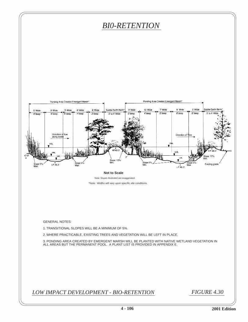
Not to ScaleNote: Slopes illustrated are exaggerated.
*Note: Widths will vary upon specific site conditions.
LOW IMPACT DEVELOPMENT - BIO-RETENTION FIGURE 4.30
4 - 106
BI0-RETENTION
GENERAL NOTES:
1. TRANSITIONAL SLOPES WILL BE A MINIMUM OF 5%.
2. WHERE PRACTICABLE, EXISTING TREES AND VEGETATION WILL BE LEFT IN PLACE.
3. PONDING AREA CREATED BY EMERGENT MARSH WILL BE PLANTED WITH NATIVE WETLAND VEGETATION INALL AREAS BUT THE PERMANENT POOL. A PLANT LIST IS PROVIDED IN APPENDIX E.
2001 Edition

5.0
ORDINANCE AND REGULATIONS
Storm Water Quality Management 5 - 1 2001 EditionGuidance Manual
5.0 ORDINANCE AND REGULATIONS
The City of Houston Storm Water Discharges Ordinance and the Regulations of Harris County,Texas for Storm Water Quality Management are available on the Storm Water Management JointTask Force website: http://www.cleanwaterclearchoice.org. The City of Houston ordinance is alsoavailable at the City of Houston’s Department of Public Works and Engineering’s Plan ReviewDesk, 611 Walker, 2nd Floor, Houston, Texas, and at the City of Houston’s Storm Sewer ReviewDesk, 3300 Main, 2nd Floor, Houston, Texas. The Harris County regulations are also available atthe Harris County Public Infrastructure Department – Permit Office, 9900 Northwest Freeway,Suite 103, Houston, Texas.

APPENDIX A
GUIDANCE FOR PLAN SUBMITTAL ANDIMPLEMENTATION REVIEW

Storm Water Quality Management App. A - 1 2001 EditionGuidance Manual
City of Houston and Harris County procedures for the New Development / SignificantRedevelopment Program are available on the Storm Water Management Joint Task Forcewebsite: http://www.cleanwaterclearchoice.org.

APPENDIX B
INSPECTION CHECKLISTS FOR NON-STRUCTURAL BEST MANAGEMENT PRACTICES (BMPS)

Storm Water Quality Management App. B - 1 2001 EditionGuidance Manual
APPENDIX B
INSPECTION CHECKLISTSFOR NON-STRUCTURAL (SOURCE CONTROL)
BEST MANAGEMENT PRACTICES (BMPS)
Note:
Sample inspection and maintenance checklists for non-structural best management practices(BMPs) provided in this appendix were derived from various sources. The checklists providegeneral guidance and may need adaptation for use with a specific practice or site conditions,subject to the review and approval of the local agency with jurisdiction. The completedchecklists should be maintained at an accessible location, for examination by the local agencywith jurisdiction.
Tables B.1 and B.2 are provided as guidance for multiple checklist application, to use forinspection and monitoring of a program with multiple non-structural controls.

Storm Water Quality Management App. B - 2 2001 EditionGuidance Manual
Table B.1 – Applicable Non-Structural Controls
Potential Pollutant-Causing Activity ActivityLocated onSite ( )
Applicable Non-Structural Control Ref. #
Uncovered vehicle parking Street Sweeping 4.1.12Trash disposal Litter Control 4.1.2Washing of vehicle or equipment Vehicle/Equipment Washing and
Steam Cleaning4.1.6
Vehicle or equipment fueling Fueling Station 4.1.5Loading or unloading of liquid materials Liquid Materials Loading and
Unloading4.1.7
Storage of raw materials, by-products orproducts of manufacturing processes
Outdoor StorageOutdoor ManufacturingSpill Prevention and Response Plan
4.1.114.1.124.1.10
Above-ground bulk storage of fuel,petroleum or chemicals
Liquids Storage in AbovegroundTanksLiquid Materials Loading andUnloadingSpill Prevention and Response Plan
4.1.8
4.1.7
4.1.10Underground tanks Liquid Materials Loading and
UnloadingSpill Prevention and Response Plan
4.1.74.1.10
Use of pesticides or fertilizers Household Hazardous MaterialsStorage/DisposalLandscaping PracticeFertilizer and Pesticide Use
4.1.14.1.24.1.4
Temporary storage of liquid or solidwastes Type of waste:
Hazardous Waste
Food Waste
Used Oil/Antifreeze
Underground drainage system
Liquids Storage in AbovegroundTanksContainer Storage of LiquidsSpill Prevention and Response PlanContainer Storage of LiquidsSpill Prevention and Response PlanContainer Storage of LiquidsSpill Prevention and Response PlanHousehold Hazardous MaterialsStorage/Disposal (recyclingoil/antifreeze)Inlet Stenciling
4.1.84.1.94.1.104.1.94.1.104.1.94.1.10
4.1.14.1.13
ANY OTHER ACTIVITIES NOT COVERED ABOVE:

TABLE B-2: NON-STRUCTURAL CONTROL MATRIX
Household Hazardous Materials Storage/Disposal (4.1.1)Litter Control (4.1.2)
Landscaping Practices (4.1.3)Fertilizer and Pesticide Use (4.1.4)
Fueling Station Practices (4.1.5)Vehicle/Equipment Washing and Steam Cleaning Practices (4.1.6)
Liquid Materials Loading and Unloading Practices (4.1.7)Liquids Storage in Above Ground Tanks (4.1.8)
Container Storage of Liquids, Food Wastes, Hazardous Wastes (4.1.9)Spill Prevention and Response Plan (4.1.10)
Outdoor Storage Practices (4.1.11)Street Sweeping (4.1.12)
Storm W
ater Quality M
anagement
Guidance
Manual
Inlet Stencilling (4.1.13)
LAND USE:
MANUFACTURING BUSINESSES:
Cement
Chemicals
Concrete Products
Electrical Products
Food Products
App. B
- 3
Glass Products
Machinery And Equipment
Metal Products
Paper And Pulp Mills
Paper Products
Petroleum Products
Printing And Publishing
Rubber And Plastic Products
Ship And Boat Building/Repair Yards
Wood Products
Wood Treatment
TRANSPORTATION AND COMMUNICATION:
2001 Edition
Airfields/Aircraft Maintenance

TABLE B-2: NON-STRUCTURAL CONTROL MATRIX, continued
Household Hazardous Materials Storage/Disposal (4.1.1)Litter Control (4.1.2)
Landscaping Practices (4.1.3)Fertilizer and Pesticide Use (4.1.4)
Fueling Station Practices (4.1.5)Vehicle/Equipment Washing and Steam Cleaning Practices (4.1.6)
Liquid Materials Loading and Unloading Practices (4.1.7)Liquids Storage in Above Ground Tanks (4.1.8)
Container Storage of Liquids, Food Wastes, Hazardous Wastes (4.1.9)Spill Prevention and Response Plan (4.1.10)
Outdoor Storage Practices (4.1.11)Street Sweeping (4.1.12)
Storm W
ater Quality M
anagement
Guidance
Manual
Inlet Stencilling (4.1.13)
Fleet Vehicle Yards
Railroads
Private Utility Corridors
Warehouses And Miniwarehouses
WHOLESALE AND RETAIL BUSINESSES:
Gas Stations
Recyclers And Scrap Yards
App. B
- 4
Restaurants/Fast Food
General Merchandise
Vehicle And Equipment Dealers
Nurseries And Building Materials
Chemicals And Petroleum
Foods And Beverages
SERVICE BUSINESSES:
Commercial Car And Truck Washes
Equipment Repair
Laundries And Cleaning Services
Marinas And Boat Clubs
Professional Services
Vehicle Maintenance/Repair
2001 Edition
Construction Businesses

TABLE B-2: NON-STRUCTURAL CONTROL MATRIX, continued
Household Hazardous Materials Storage/Disposal (4.1.1)Litter Control (4.1.2)
Landscaping Practices (4.1.3)Fertilizer and Pesticide Use (4.1.4)
Fueling Station Practices (4.1.5)Vehicle/Equipment Washing and Steam Cleaning Practices (4.1.6)
Liquid Materials Loading and Unloading Practices (4.1.7)Liquids Storage in Above Ground Tanks (4.1.8)
Container Storage of Liquids, Food Wastes, Hazardous Wastes (4.1.9)Spill Prevention and Response Plan (4.1.10)
Outdoor Storage Practices (4.1.11)Street Sweeping (4.1.12)
Storm W
ater Quality M
anagement
Guidance
Manual
Inlet Stencilling (4.1.13)
SINGLE FAMILY RESIDENCES
MULTIFAMILY RESIDENCES
PUBLIC FACILITIES
Public Buildings And Streets
Vehicle And Equipment Maintenance Facilities
Maintenance Of Open Space
Maintenance Of Public Storm Water Facilities
App. B
- 5
Maintenance Of Roadside Vegetation/Ditches
Maintenance Of Public Utilities Corridors
Maintenance Of Water And Sewer Facilities
Port Districts
INSTITUTIONAL
Schools
Hospitals
Sports Facilities (Stadia)
OPEN SPACE
Golf Courses Parks
2001 Edition

Storm Water Quality Management App. B - 6 2001 EditionGuidance Manual
Sample Inspection and Maintenance Checklists4.1 NON-STRUCTURAL CONTROLS
4.1.1 Household Hazardous Material Storage / Disposal4.1.2 Litter Control4.1.3 Landscaping Practices4.1.4 Fertilizer and Pesticides4.1.5 Fueling Station Practices4.1.6 Vehicle / Equipment Washing and Steam Cleaning Practices4.1.7 Liquid Materials Loading and Unloading Practices4.1.8 Liquids Storage in Above-ground Tanks Practices4.1.9 Container Storage of Liquids, Food Wastes, Hazardous Wastes4.1.10 Spill Prevention and Response Plan4.1.11 Outdoor Storage Practices4.1.12 Street Sweeping4.1.13 Inlet Stenciling

4.1.1.a HOUSEHOLD HAZARDOUS MATERIALS STORAGE / DISPOSAL
Inspection Date______________ By:Time ______________ Location:
Item Household Hazardous Materials LIST BELOW (Use less toxic alternatives where feasible)
Storage Location
Securely stored, safe from
children/pets and protected from
Correction Action/By
Corrected Date
Collection Center
Location
Date(s) Recycling Center
Location
Date(s)
1 Paints
2 Cleaning Products
3 Automotive
4 Other
Comments:
2001 Edition
App. B - 7
Storm Water Quality
Management Guidance Manual

4.1.1.b COMMERCIAL / INDUSTRIAL CHEMICAL / MATERIAL AREAS
Inspection Date______________ By:Time ______________ Location:
ITEM Site Specific Checklist For Chemical/Material Storage Areas
Yes/No/NA Correction Action/By
Corrected Date
Notes
1 Hazardous material containers are properly labeled.2 MSDS are readily accessible.3 Indoor containers/drums are stored on pallets.4 Outdoor containers/drums are protected from
precipitation.5 Spill response container is placed with hazardous
materials that are stored covered outdoors.6a. Secondary containment is in use.6b. If yes, describe materials that are provided secondary
containment and where are the materials located. _________________________________________
7 Containers/drums are in good condition with no corrosion.
8 Drain funnels or air pumps are used for fluid transferal?
9a. Spill control equipment is nearby and available to use if a spill suddenly occurs. Exclude spill response containers that are discussed in question 5.
9b. List available spill equipment: ______________________
10 Annual inspections and corrective actions for storage areas are documented and kept onsite?
11 Rags or wipes used with solvents/thinners, or other hazardous cleaning fluids are collected and handled appropriately according to applicable local, state or federal regulations.
12 Outside dumpsters are covered.II. Good Housekeeping Checklist For
Chemical/Material Storage Areas1 Bags are in good condition with no tears evident.2 Dry-bulk material in bags is not exposed to wind or rain.
3 Paper waste, spent rags/cloths, and other waste products are properly segregated, handled and stored while awaiting disposal.
4 Visual inspections or leak tests been performed for overhead piping conveying Section 313 chemicals w/o sec. containment.
5a. Owner/Operator has a spill response plan.5b. If yes, a copy should be kept onsite and additional copy
should be provided to the PPP during annual inspection.
Comments:
Storm Water Quality ManagementGuidance Manual
App. B - 8 2001 Edition

4.1.2 LITTER CONTROL
Inspection Date______________ By:Time ______________ Location:
ITEM DESCRIPTION Yes/No/NA Correction Action/By
Corrected Date
Notes
1 HOUSEHOLD WASTE1.1 Routine waste is securely contained (garbage containers,
dumpsters, etc.)1.2 Use of recycling program / facilities.1.3 Other method practiced. (Describe below)
2 COMMERCIAL AND INDUSTRIAL WASTE2.1 Routine waste is securely contained (garbage containers,
dumpsters, etc.)2.2 Use of recycling program / facilities.2.3 Frequent daily inspection of immediate area around
storage areas.2.4 Litter containers are conveniently placed and disposed
frequently.
3 HAULING VEHICLES3.1 Cover over loose material.3.2 Use of sealed bottoms for equipment.
4 LOADING DOCKS4.1 Dock swept regularly.
5 CONSTRUCTION SITE (SEE PRACTICES GIVEN IN "STORM WATER MANAGEMENT FOR CONSTRUCTION ACTIVITIES")
6 MOTORISTS AND PEDESTRIANS6.1 Secure vacant lots and vegetated areas.6.2 Provide litterbags or baskets.
7 OTHER ITEM (DESCRIBE ITEM AND GIVE COMMENTS)
Storm Water Quality ManagementGuidance Manual
App.B - 9 2001 Edition

4.1.3 LANDSCAPING PRACTICES
Inspection Date______________ By:Time ______________ Location:
ITEM DESCRIPTION Yes/No/NA Correction Action/By
Corrected Date
Notes
1 WATERING AND MOWING: (guidelines)1.1 Deep Watering (about 1") no more than every 5 or 6
days.1.2 Mulching mower used, kept in good condition.1.3 Other method practiced. (Describe below)
2 XERISCAPING (USE OF NATIVE PLANTS)2.1 Locations (List below):
3 OTHER ITEM (DESCRIBE ITEM AND GIVE COMMENTS)
Storm Water Quality ManagementGuidance Manual
App. B - 10 2001 Edition

4.1.4 FERTILIZER AND PESTICIDE USE
Inspection Date______________ By:Time ______________ Location:
ITEM DESCRIPTION Yes/No/NA Correction Action/By
Corrected Date
Notes
1 FERTILIZER USE (guidelines)1.1 Use of native or low maintenance landscaping as
feasible to minimize fertilize use.1.2 Soil test conducted (recommended).1.3 Fertilize warm season grasses (Bermuda, Bahia,
Centipede, St. Augustine) in the spring or summer.1.4 Fertilize cool season grasses (Ryegrass) in the fall or
early winter.1.5 Apply fertilizer when soil moisture is adequate, and
little likelihood of heavy rain.1.6 Sprinkle lawn after application.1.7 Prevent spill on impervious areas. 1.8 Other method practiced. (Describe below)
2 PESTICIDES AND HERBICIDES USE2.1 Use of pest resistant vegetation and proper care to
minimize pesticide use.2.2 Label all products used. 2.3 Non-toxic alternatives or least toxic chemicals used.
(List below)
2.4Apply on affected areas and under windless conditions.
2.5 Proper storage and disposal. 2.6 Certification or licensing for commercial or institutional
applicators.2.7 Use of Integrated Pest Management program if
practicable.2.8 Other method currently practiced.
(Describe below)
3 OTHER ITEM (DESCRIBE ITEM AND GIVE COMMENTS)
Storm Water Quality ManagementGuidance Manual
App. B - 11 2001 Edition

4.1.5 FUELING STATION PRACTICES
Inspection Date______________ By:Time ______________ Location:
ITEM DESCRIPTION Yes/No/NA Correction Action/By
Corrected Date
Notes
1 FACILITIES AND EQUIPMENT1.1 Canopy over fuel island.1.2 Condition of Drain on "downhill"
side of island is satisfactory. (Should be connected to sump, process treatment, or where permitted, to the sanitary sewer.)
1.3 Condition of positive control valve for drain is satisfactory.
1.4Condition of sump, if used, is satisfactory.(Oily residuals indicate need for cleanup.)
1.5 Condition of oil/water separator, if used, is satisfactory.(Complete Oil/Grit Separator inspection checklist. Oily residuals indicate need for cleanup.)
1.6 Other:
2 REQUIRED MAINTENANCE AND/OR REPAIRS:
Storm Water Quality ManagementGuidance Manual
App. B - 12 2001 Edition

4.1.6 VEHICLE / EQUIPMENT WASHING AND STEAM CLEANING PRACTICES
Inspection Date______________ By:Time ______________ Location:
ITEM DESCRIPTION Yes/No/NA Correction Action/By
Corrected Date
Notes
1 FACILITIES AND EQUIPMENT (guidelines)1.1 Wash water contained and treated by a closed-loop
recycling system, or discharge in process treatment.1.2 Uncovered wash areas are paved, protected from storm
water flow from adjacent areas.1.3 Condition of catch basin, if used, is satisfactory.
(Oily residuals indicates need for cleanup. Complete Catch Basin Inspection checklist.)
1.5 Condition of oil/water separator, if used, is satisfactory.
(Complete Oil/Grit Separator inspection checklist. Oily residuals indicate need for cleanup.)
1.7 Signing forbidding oil changing near wash facility.1.8 Soap, if used, is low phosphate type (for residential car
washing only.)1.9 Other method currently practiced. Describe below.
2 REQUIRED MAINTENANCE AND/OR REPAIRS:
Storm Water Quality ManagementGuidance Manual
App. B - 13 2001 Edition

4.1.7 LIQUID MATERIALS LOADING AND UNLOADING PRACTICES
Inspection Date______________ By:Time ______________ Location:
ITEM DESCRIPTION Yes/No/NA Correction Action/By
Corrected Date
Notes
1 CONTAINED LIQUIDS AT LOADING AND UNLOADING DOCKS (guidelines)
1.1 Condition of overhangs or door skirts is satisfactory.1.2 Spill cleanup materials in readily accessible location,
and well maintained.1.3 Other method currently practiced. Describe below.
2 BULK LOADING /UNLOADING 2.1 Written operation plan is current and practiced by
employees.2.2 Drip pan used where spillage may occur.2.3 Spillage of drip pans residuals are cleaned up.2.4 Other method currently practiced. Describe below.
3 REQUIRED MAINTENANCE AND OR REPAIRS:
Storm Water Quality ManagementGuidance Manual
App. B - 14 2001 Edition

4.1.8 LIQUIDS STORAGE IN ABOVEGROUND TANK PRACTICES
Inspection Date______________ By:Time ______________ Location:
ITEM DESCRIPTION Yes/No/NA Correction Action/By
Corrected Date
Notes
1 PERMANENT TANK STORAGE (guidelines)1.1 Condition of tank overfill protection system is
satisfactory.1.2 Condition of containment dike(s) around tank(s) is
satisfactory.1.3 Condition of impervious surface within dike is
satisfactory.1.4 Condition of positive control valve on outlet is
satisfactory.1.5 Condition of small spill sump is satisfactory.
(Presence of residuals indicates need for cleanup.)1.6 Accumulated storm water released frequently during
rainy periods (if not exposed to the stored liquids.)1.7 Condition of Oil/Grit Separator (for petroleum tanks or
other heavy use area) is satisfactory. Complete Oil/Grit Separator inspection checklist.
1.8 Other:
2 SPILL RESPONSE PLAN:2.1 Spill Response Plan is available in readily accessible
location.2.2 Date of last update to Spill Response Plan: __________
3 REQUIRED MAINTENANCE AND OR REPAIRS:
Storm Water Quality ManagementGuidance Manual
App. B - 15 2001 Edition

4.1.9 CONTAINER STORAGE OF LIQUIDS, FOOD WASTES, HAZARDOUS WASTES
Inspection Date______________ By:Time ______________ Location:
ITEM DESCRIPTION Yes/No/NA Correction Action/By
Corrected Date
Notes
1 FACILITIES AND EQUIPMENT (guidelines)1.1 Waste containers kept in protective structures (lean-to,
service bay, etc.) while awaiting transfer.1.2 Condition of impervious surface under containers with
liquids is satisfactory.1.3 Condition of curb or dike around containers with liquids
is satisfactory.1.4 Condition of sump collecting drainage from storage area
is satisfactory.(Presence of residuals indicates need for cleanup.)
1.5 Drip pan use under containers fixed with valves or spigots is satisfactory.
1.6 Employee trained in spill control/cleanup is present during loading/unloading activity.
1.7 Spill cleanup materials is readily accessible location, and well maintained.
1.8 Other:
2 REQUIRED MAINTENANCE AND OR REPAIRS:
Storm Water Quality ManagementGuidance Manual
App. B - 16 2001 Edition

4.1.10 SPILL PREVENTION AND RESPONSE PLAN
Inspection Date______________ By:Time ______________ Location:
ITEM DESCRIPTION Yes/No/NA Correction Action/By
Corrected Date
Notes
1 Spill Prevention and Response PLAN (guidelines)
1.1 Spill Preventionand Response procedures have been developed for the site.
1.2 Team is designated with spill response cleanup responsibility.
1.3 Summary of Spill Preventionand Response plan posted at appropriate locations.
1.4 Spill cleanup materials in readily accessible location and well maintained.
1.5 Personnel are trained in spill containment and response procedures.
1.6 Other:Spill notification list is part of plan.Contingency Plan in case of catastrophic spill.
2 REQUIRED MAINTENANCE AND OR REPAIRS:
Storm Water Quality ManagementGuidance Manual
App. B - 17 2001 Edition

4.1.11 OUTDOOR STORAGE PRACTICES
Inspection Date______________ By:Time ______________ Location:
ITEM DESCRIPTION Yes/No/NA Correction Action/By
Corrected Date
Notes
1 RAW MATERIALS, BUILDING MATERIALS, AND CONCRETE AMD METAL PRODUCTS (guidelines)
1.1 Condition of covered area is satisfactory.1.2 Condition of paved area on which materials are stored is
satisfactory.1.3 Plastic sheeting used over material (for raw materials.)
1.4 Condition of drainage system and structural control is satisfactory. Complete appropriate inspection checklist for structural control.
1.5 Other:
2 OTHER ITEM (DESCRIBE ITEM AND GIVE COMMENTS)
3 REQUIRED MAINTENANCE AND/OR REPAIRS:
Storm Water Quality ManagementGuidance Manual
App. B - 18 2001 Edition

4.1.12 STREET SWEEPING
Inspection Date______________ By:Time ______________ Location:
ITEM DESCRIPTION Yes/No/NA Correction Action/By
Corrected Date
Notes
1 PRACTICES1.1 Vacuum-type or regenerate sweepers used.1.2 Sweeping frequency of at least bi-weekly. 1.3 Operators instructed to exceed 6 mph. Sweeping speed
and to make 2 sweeping passes.1.4 Sweeping disposed of at an approved landfill site.1.5 Other:
2 OTHER ITEM (DESCRIBE ITEM AND GIVE COMMENTS)
3 REQUIRED MAINTENANCE AND/OR REPAIRS:
Storm Water Quality ManagementGuidance Manual
App. B - 19 2001 Edition

4.1.13 STORM DRAIN INLET STENCILING
Inspection Date______________ By:Time ______________ Location:
ITEM DESCRIPTION Yes/No/NA Correction Action/By
Corrected Date
Notes
1 PRACTICES1.1 Signs painted on or adjacent to all storm drain inlets
noting receiving waters and warning against dumping.1.2 Stenciled message on concrete or metal plates on or
adjacent to storm drain inlets noting receiving waters and warning against dumping
1.3 Other:
2 REQUIRED MAINTENANCE AND/OR REPAIRS:
Storm Water Quality ManagementGuidance Manual
App. B - 20 2001 Edition

4.1.14 OUTDOOR MANUFACTURING PRACTICES
Inspection Date______________ By:Time ______________ Location:
ITEM DESCRIPTION Yes/No/NA Correction Action/By
Corrected Date
Notes
1 COVERED ACTIVITY (NOT TOTALLY ENCLOSED)
1.1 Condition of sump collecting drainage activity area is satisfactory.(Presence of residuals indicates need for cleanup.)
1.2 Other method currently practiced. Describe below.
2 SEGREGATED EXPOSED ACTIVITY2.1 Condition of curbing around activity is satisfactory.2.2 Condition of impervious surface on which activity is
located is satisfactory.2.3 Condition of drainage system and process control is
satisfactory. Complete appropriate inspection checklist for structural control.
2.4 Other method currently practiced. Describe below.
2 OTHER ITEM (DESCRIBE ITEM AND GIVE COMMENTS)
3. REQUIRE MAINTENANCE AND/OR REPAIRS:
Storm Water Quality ManagementGuidance Manual
App. B - 21 2001 Edition

4.1.15 RECYCLING MOTOR OIL AND ANTIFREEZE
Inspection Date______________ By:Time ______________ Location:
ITEM DESCRIPTION Yes/No/NA Correction Action/By
Corrected Date
Notes
1 PRACTICES1.1 Information posted on recycling procedures.1.2 Locations of recycling or collection centers posted.1.3 Covered protected area provided for temporary storage
of materials/fluids for recycling. (complete appropriate inspection checklist for covered area for hazardous materials.)
1.4 Temporary storage area for recycle materials is kept neat, clean.
1.5 Other method currently practiced. Describe below.
2 OTHER ITEM (DESCRIBE ITEM AND GIVE COMMENTS)
3 REQUIRE MAINTENANCE AND/OR REPAIRS:
Storm Water Quality ManagementGuidance Manual
App. B - 22 2001 Edition

APPENDIX C
INSPECTION CHECKLISTS FOR STRUCTURAL BEST MANAGEMENT PRACTICES (BMPs)

Storm Water Quality Management App. C - 1 2001 Edition
APPENDIX C
INSPECTION CHECKLISTSFOR STRUCTURAL
BEST MANAGEMENT PRACTICES (BMPs)
Note:
Sample inspection and maintenance checklists for structural best management practices (BMPs)are provided in this appendix to aid the owner and/or operator of a BMP, in inspecting andmaintaining a BMP. The forms were derived from various sources. The sample forms aregeneralized and may need adaptation for use with a specific practice or site conditions, subject tothe review and approval of the local agency with jurisdiction. The completed checklists shouldbe maintained at an accessible location, for examination by the local agency with jurisdiction.

Storm Water Quality Management App. C - 2 2001 Edition
Sample Inspection and Maintenance Checklists
4.2 WATER QUALITY BASINS4.2.1 Dry Basins4.2.2 Wet Ponds4.2.4 Wetland Treatment
4.4 CATCHMENT FACILITIES4.4.1 Catch Basins4.4.2 Oil/Grit Separators
4.5 VEGETATIVE PRACTICES4.5.1 Grassed Swales4.5.2 Vegetated Filter Strips

4.2.1 DRY BASINS
Inspection Date______________ By:Time ______________ Location:
ITEM DESCRIPTION Yes/No/NA Correction Action/By
Corrected Date Notes
1 SEDIMENT REMOVAL1.1 Design depth (feet): ____________
1.2 Sediment thickness:____________ (Measure sediment thickness directly, or measure current depth and subtract from design depth to arrive at sediment thickness. Remove sediment if thickness exceeds 1/3 of design depth.)
2 EMBANKMENT2.1 Evidence of subsidence. 2.2 Presence of erosion.2.3 Presence of crack.2.4 Presence of tree growth. 2.5 Presence burrowing animals. 2.6 Other. Describe below.
2.7 Explanation:
3 OUTFALL3.1 Emergency spillway. 3.2 Outlet. 3.3 Discharge control such as valve, riser/barrel, weir, check dam,
and other. 3.4 Other. Describe below.
3.5 Explanation:
4 DRAW DOWN TIMEDesign volume drains less than 24 hours or remains 72 hours or more after a storm. If answer is yes, outfall or outlet control should be checked, cleaned or adjusted as needed.
5 CONTRIBUTORY DRAINAGE5.1 Inlet condition is satisfactory.5.2 Upstream channel conditions are satisfactory.5.3 Upstream erosion controls are satisfactory.5.4 Upstream sediment controls are satisfactory. 5.5 Other. Describe below.
5.6 Explanation:
Storm Water Quality ManagementGuidance Manual
App. C - 3 2001 Edition

4.2.1 DRY BASINS (Continued)
Inspection Date______________ By:Time ______________ Location:
ITEM DESCRIPTION Yes/No/NA Correction Action/By
Corrected Date Notes
6 DEBRIS / LITTER REMOVAL6.1 Date of last litter removal:_____________________6.2 Removal of litter is required. (Required if last litter removal
was 6 months ago or earlier.)7 MOWING
7.1 Date of last mowing performed:________________7.2 Mowing required. ( Required if last mowing was 6 months ago
or earlier or if trees or woody shrubs are present on embankment.)
8 NUISANCE CONTROL8.1 Presence of insects.8.2 Presence of weeds8.3 Presence of odors.8.4 Other. Describe below.
8.5 Explanation:
9 STRUCTURAL REPAIRS/REPLACEMENTDescribe any item needing structural repair and replacement below.
10 OTHER ITEM. Describe item and condition. Explain any problem below.
REQUIRED MAINTENANCE AND /OR REPAIRS:
Storm Water Quality ManagementGuidance Manual
App. C - 4 2001 Edition

4.2.2 WET PONDS
Inspection Date______________ By:Time ______________ Location:
ITEM DESCRIPTION Yes/No/NA Correction Action/By
Corrected Date Notes
1 SEDIMENT REMOVAL1.1 Design depth of forebay (feet): ____________.1.2 Sediment thickness of forebay:____________ (Measure sediment
thickness directly, or measure current depth and subtract from design depth to arrive at sediment thickness. Remove sediment if thickness exceeds 1/3 of design depth.)
1.3 Design depth of other location (feet): _____________.
1.4 Sediment thickness of other location:____________. (Measure sediment thickness directly, or measure current depth and subtract from design depth to arrive at sediment thickness. Remove sediment if thickness exceeds 1/3 of design depth.)
2 EMBANKMENT2.1 Evidence of subsidence. 2.2 Presence of Erosion.2.3 Presence of crack.2.4 Presence of tree growth. 2.5 Presence burrowing animals. 2.6 Other. Describe below.
2.7 Explanation:
3 OUTFALL3.1 Emergency spillway. 3.2 Other. Describe below.
Explanation:
4 CONTRIBUTORY DRAINAGE4.1 Inlet4.2 Upstream channel conditions.4.3 Upstream erosion controls.4.4 Upstream sediment controls. 4.5 Other. Describe below.
4.6 Explanation:
Storm Water Quality ManagementGuidance Manual
App. C - 5 2001 Edition

4.2.2 WET PONDS (continued)
Inspection Date______________ By:Time ______________ Location:
ITEM DESCRIPTION Yes/No/NA Correction Action/By
Corrected Date Notes
5 DEBRIS / LITTER REMOVAL5.1 Date of last litter removal:_____________________5.2 Removal of litter is required. (Required if last litter removal was
6 months ago or earlier.)6 MOWING
6.1 Date of last mowing performed:__________________________
6.2 Mowing required. ( Required if last mowing was 6 months ago or earlier or if trees or woody shrubs are present on embankment.)
7 NUISANCE CONTROL7.1 Presence of insects.7.2 Presence of weeds7.3 Presence of odors.7.4 Other. Describe below.
7.5 Explanation:
8 STRUCTURAL REPAIRS/REPLACEMENTDescribe any item needing structural repair and replacement below.
9 OTHER ITEM. Describe item and condition. Explain any problem below.
REQUIRED MAINTENANCE AND /OR REPAIRS:
Storm Water Quality ManagementGuidance Manual
App. C - 6 2001 Edition
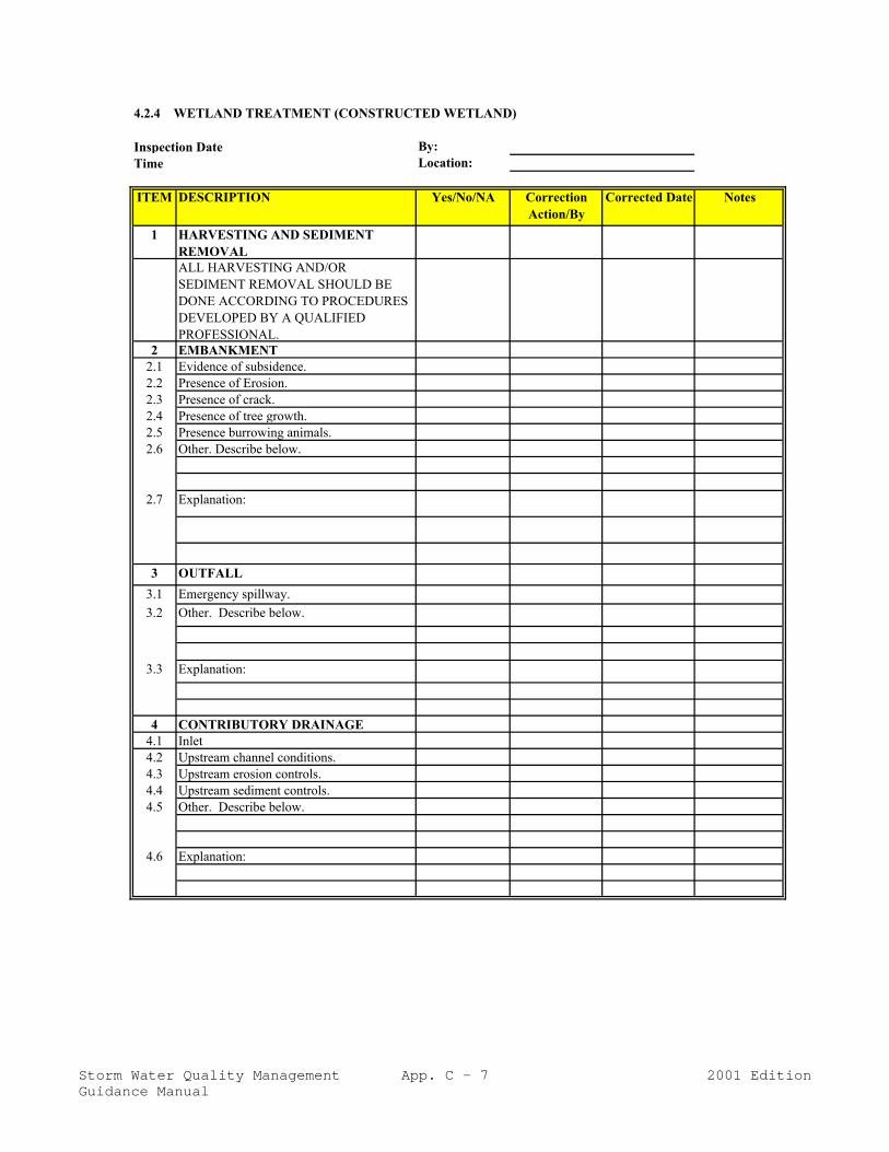
4.2.4 WETLAND TREATMENT (CONSTRUCTED WETLAND)
Inspection Date______________ By:Time ______________ Location:
ITEM DESCRIPTION Yes/No/NA Correction Action/By
Corrected Date Notes
1 HARVESTING AND SEDIMENT REMOVALALL HARVESTING AND/OR SEDIMENT REMOVAL SHOULD BE DONE ACCORDING TO PROCEDURES DEVELOPED BY A QUALIFIED PROFESSIONAL.
2 EMBANKMENT2.1 Evidence of subsidence. 2.2 Presence of Erosion.2.3 Presence of crack.2.4 Presence of tree growth. 2.5 Presence burrowing animals. 2.6 Other. Describe below.
2.7 Explanation:
3 OUTFALL3.1 Emergency spillway. 3.2 Other. Describe below.
3.3 Explanation:
4 CONTRIBUTORY DRAINAGE4.1 Inlet4.2 Upstream channel conditions.4.3 Upstream erosion controls.4.4 Upstream sediment controls. 4.5 Other. Describe below.
4.6 Explanation:
Storm Water Quality ManagementGuidance Manual
App. C - 7 2001 Edition

4.2.4 WETLAND TREATMENT (CONSTRUCTED WETLAND) (continued)
Inspection Date______________ By:Time ______________ Location:
ITEM DESCRIPTION Yes/No/NA Correction Action/By
Corrected Date Notes
5 DEBRIS / LITTER REMOVAL5.1 Date of last litter removal:_____________________5.2 Removal of litter is required. (Required if last litter removal was
6 months ago or earlier.)6 EMBANKMENT MOWING
6.1 Date of last mowing performed:__________________________
6.1 Mowing is required. ( Required if last mowing was 6 months ago or earlier or if trees or woody shrubs are present on embankment.)
7 NUISANCE CONTROL7.1 Presence of insects.7.2 Presence of weeds7.3 Presence of odor.7.4 Other. Describe below.
7.5 Explanation:
8 STRUCTURAL REPAIRS/REPLACEMENTDescribe any item needing structural repair and replacement below.
9 OTHER ITEM. Describe item and condition. Explain any problem below.
REQUIRED MAINTENANCE AND /OR REPAIRS:
Storm Water Quality ManagementGuidance Manual
App. C - 8 2001 Edition

4.4.1 CATCH BASINS
Inspection Date______________ By:Time ______________ Location:
ITEM DESCRIPTION Yes/No/NA Correction Action/By
Corrected Date Notes
1 CATCH BASINS1.1 Presence of debris accumulation. (Remove any accumulation of
debris.)1.2 Evidence of sediment accumulation. (Remove any substantial
accumulation of sediment. Suggested guidelines removal guideline: 1 inch or more present. Note: lack of sediment after a significant rainfall indicates flushing and need for more frequent inspection and cleaning to avoid loss of sediment during flushing.)
1.3 Presence of sheen, odor, or visible. 1.4 Presence of oil in chamber. Clean, if answer yes and if last
cleaning date was 6 months ago or earlier.1.5 Other. Describe below.
1.6 Explanation:
2 OUTFALL2.1 Outlets. 2.2 Other. Describe below.
2.3 Explanation:
3 CONTRIBUTORY DRAINAGE3.1 Inlet condition is satisfactory.3.2 Upstream channel conditions are satisfactory.3.3 Upstream erosion controls are satisfactory.3.4 Upstream sediment controls are satisfactory.3.5 Other. Describe below.
3.6 Explanation:
4 NUISANCE CONTROL4.1 Presence of insects.4.2 Presence of weeds4.3 Presence of odors.4.4 Other. Describe below.
4.5 Explanation:
5 STRUCTURAL REPAIRS/REPLACEMENTDescribe any item needing structural repair and replacement below.
6 OTHER ITEM. Describe item and condition. Explain any problem below.
REQUIRED MAINTENANCE AND /OR REPAIRS:
Storm Water Quality ManagementGuidance Manual
App. C - 9 2001 Edition

4.4.2 OIL GRIT SEPARATORS (Water Quality Inlets)
Inspection Date______________ By:Time ______________ Location:
ITEM DESCRIPTION Yes/No/NA Correction Action/By
Corrected Date Notes
1 OIL/GRIT SEPARATOR1.1 Presence of debris accumulation. (Remove any accumulation of
debris.)1.2 Evidence of sediment accumulation. (Remove any substantial
accumulation of sediment. Suggested guidelines removal guideline: 1 inch or more present. Note: lack of sediment after a significant rainfall indicates flushing and need for more frequent inspection.
1.3 Condition of adsorbent pillows. (Replace with any cleaning, if oily.)
1.4 Presence of sheen, odor, or visible. (Clean if present or if last cleaning date was 6 months ago or earlier)
1.5 Condition of coalescing plates. (Indicate any damage, clogging, oily condition, etc. Clean if last cleaning was 6 months a go or earlier.)
1.6 Other. Describe below.
1.7 Explanation:
2 OUTFALL2.1 Outlets. 2.2 Discharge control such as orifice and other type. 2.3 Other. Describe below.
2.4 Explanation:
3 CONTRIBUTORY DRAINAGE3.1 Inlet condition is satisfactory.3.2 Upstream channel conditions are satisfactory.3.3 Upstream erosion controls are satisfactory.3.4 Upstream sediment controls are satisfactory.3.5 Other. Describe below.
3.6 Explanation:
4 NUISANCE CONTROL4.1 Presence of insects.4.2 Presence of weeds4.3 Presence of odors.4.4 Other. Describe below.
4.5 Explanation:
5 STRUCTURAL REPAIRS/REPLACEMENTDescribe any item needing structural repair and replacement below.
6 OTHER ITEM. Describe item and condition. Explain any problem below.
REQUIRED MAINTENANCE AND /OR REPAIRS:
Storm Water Quality ManagementGuidance Manual
App. C - 10 2001 Edition

4.5.1 GRASSED SWALES
Inspection Date______________ By:Time ______________ Location:
ITEM DESCRIPTION Yes/No/NA Correction Action/By
Corrected Date Notes
1 CHANNEL CONDITION1.1 Presence of spot or area erosion. 1.2 Presence of bare spots. 1.3 Presence of weeds. 1.4 Presence of standing water. 1.5 Presence of sediment deposits. 1.6 Other. Describe below.
1.7 Explanation:
2 DEBRIS / LITTER REMOVAL2.1 Date of last litter removal:______________
2.2 Removal of litter is required. (Required if last litter removal was 6 months ago or earlier.)
3 MOWING3.1 Date of last mowing performed:_____________
3.2 Mowing required. ( Required if last mowing was 6 months ago or earlier or if trees or woody shrubs are present on embankment.)
4 STRUCTURAL REPAIRS/REPLACEMENTDescribe any item needing structural repair and replacement below.
5 OTHER ITEM. Describe item and condition. Explain any problem below.
REQUIRED MAINTENANCE AND /OR REPAIRS:
Storm Water Quality ManagementGuidance Manual
App. C - 11 2001 Edition

4.5.2 VEGETATED FILTER STRIPS
Inspection Date______________ By:Time ______________ Location:
ITEM DESCRIPTION Yes/No/NA Correction Action/By
Corrected Date Notes
1 NATURAL FILTER STRIPS1.1 Presence of spot or area erosion. 1.2 Presence of bare spots. 1.3 Presence of standing water. 1.4 Presence of short-circuiting (channel / rills / gullies). 1.5 Presence of debris / litter. 1.6 Other. Describe below.
1.7 Explanation:
2 LAWN OR MEADOW FILTER STRIPS2.1 Presence of spot or area erosion. 2.2 Presence of bare spots. 2.3 Presence of weeds. 2.4 Presence of standing water. 2.5 Presence of short-circuiting (channel / rills / gullies). 2.6 Presence of sediment deposits. 2.7 Other. Describe below.
2.8 Explanation:
3 MOWING (LAWN OR MEADOW FILTER STRIPS)3.1 Date of last mowing performed:_____________3.2 Mowing required. ( Required if last mowing was 6 months ago or
earlier or if trees or woody shrubs are present on embankment.)
4 STRUCTURAL REPAIRS/REPLACEMENTDescribe any item needing structural repair and replacement below.
5 OTHER ITEM. Describe item and condition. Explain any problem below.
REQUIRED MAINTENANCE AND /OR REPAIRS:
Storm Water Quality ManagementGuidance Manual
App. C - 12 2001 Edition

APPENDIX D
PROPOSED COMPREHENSIVE MASTER PLANS FORNEW DEVELOPMENT AND SIGNIFICANT REDEVELOPMENT

CITY OF HOUSTON
PROPOSED COMPREHENSIVE MASTER PLAN FORNEW DEVELOPMENT AND SIGNIFICANT REDEVELOPMENT

HARRIS COUNTY
PROPOSED COMPREHENSIVE MASTER PLAN FORNEW DEVELOPMENT AND SIGNIFICANT REDEVELOPMENT

APPENDIX E
RECOMMENDED PLANT LIST

Storm Water Quality Management App. E - 1 2001 EditionGuidance Manual
Recommended Plant ListStorm Water Management Wetlands/Detention Basins
Houston-Galveston Gulf Coast AreaSource: Collins, 1993
(Note: Specific site conditions, regarding soils, hydrology, salinities, and loading rates will influence final plantselection per project.)
Open Water/Deep Marsh
Scientific Name Common Name Water Depth Condition/ Remarks
Cabomba caroliniana Fanwort 1’ - 4’ bushelCeratophyllum demersum Hornwort coontail 1’ - 4’ (polishing)Ceratophyllum muricatum Coontail 1’ - 4’Lemna aequinotialis Duckweed 1’ - 4’Lemna gibba Swollen duckweed 1’ - 4’Lemna minor Small duckweed 1’ - 4’Najas guadalupensis Water-naiad 1’ - 4’ rhizome/plugNelumbo lutea American waterlotus 2’ - 3’ seedNuphar elegans Spatterdock 2’ - 3’ rhizomeNuphar luteum Yellow cow-lily (Spatterdock) 2’ - 3’ bushelNymphaea odorata Waterlily 6” - 2’ rhizomePotamogeton pectinatus Sago pondweed (Fennel-Leaf) 8” - 3’ plugsSpirodella punctata Duckweed 1’ - 4’Wolffia braziliensis Dotted wolffia 1’ - 4’Wolffia columbiana Columbia wolffia 1’ - 4’
Shallow Emergent Marsh
Scientific Name Common Name Water Depth Condition/ Remarks
Acorus calamus Sweetflag 0 - 2’ rhizomeAgrostis alba Red top 0 - 4” seedAgrostis semiverticillata Water bent grass 0 - 4” seedAlisma subcordatum Water plantain 0 - 2’ rhizomeAlopercurus aequalis Short-awn foxtail 0 - 4” seedAlopercurus geniculatus Meadow foxtail 0 - 4” seedAlternanthera philoxeroides Alligator weed 0 - 2’ bushelAsclepias incarnata Swamp milkweed 0 - 4” seedBidens cernua Nodding beggar-ticks 0 - 4” seedCalopogon tuberosus Tuberous grass-pink 0 - 4” rhizome/plugCardamine bulbosa Bulbous bitter-cress 0 - 1’ plugCarex (sp.) Sedge 0 - 1’ rhizome/plugCarex blanda Woodland sedge 0 - 1’Carex cherokeensis Cherokee sedge 0 - 4” plugCarex Frankii Frank’s sedge 0 - 4” plugCarex granularis Meadow sedge 0 - 4” plugCarex hirsutella Sedge 0 - 4”Carex joorii Hummock sedge 0 - 4”Carex longii Longs sedge 0 - 4”Carex lupulina Hop sedge 0 - 4”Carex meadii Mead’s sedge 0 - 4”

Storm Water Quality Management App. E - 2 2001 EditionGuidance Manual
Shallow Emergent Marsh cont’d.
Scientific Name Common Name Water Depth Condition/ Remarks
Carex muhlenbergii var.muhlengergii
Muhlenberg sedge 0 - 4”
Carex rosea Stellate sedge 0 - 4”Carex stripata Awe-fruited sedge 0 - 4”Carex vulpinoides Fox sedge 0 - 4” plugCyperus (sp.) Flatsedge 2” - 6” rhizome/plugCyperus articulatus Jointed flatsedge 2” - 6”Cyperus brevifolius Shortleaf flatsedge 2” - 6”Cyperus compressus Poorland flatsedge 2” - 6”Cyperus giganteus Giant flatsedge 2” - 6”Cyperus odoratus Fragrant flatsedge 2” - 6”Dichanthelium scabriusculum Wooly panic grass 0 - 4” seedDichromena colorata White-topped sedge 2” - 6” rhizome/plugDichromena latifolia White-top sedge 2” - 6” rhizome/plugDryopteris ludoviciana Southern shield-fern 0 - 4” plugEchinodorus parvulus Leaf burhead 0 - 4” OBLEchinodorus rostratus Burhead 3” - 1’ rhizome/plugEleocharis acicularis Reverchon spikerush 3” - 1’ OBLEleocharis albida White spikerush 3” - 1’ OBLEleocharis macrostachys Spikerush 0 - 6” rhizome/plugEleocharis montevidensis Sand spikerush 0 - 6” rhizome/plugEleocharis obtusa Blunt spikerush 0 - 6” OBLEleocharis palustris Creeping spikerush 0 - 6” OBLEleocharis parvula Small spikerush 0 - 6” OBLEleocharis quadrangulata Four-square spikerush 3” - 1’ rhizome/plugEleocharis rostellata Beaked spikerush 0 - 6” OBLElodea canadensis Broad water-weed 0 - 2” OBLElodea nuttalli Nuttall’s water weed (I) 0 - 3” OBLElymus canadensis Nodding wild-rye 0 - 4” seedElymus virginicus Virginia wild-rye 0 - 4” seedEquisetum laevigatum Smooth scouring rush 0 - 2’ plugEquisetum hyemale Scouring rushEragrostis (sp.) Lovegrass 0 - 4” seedFimbristylis (sp.) Fimbry 0 - 4” plugGalium (sp.) Bedstraw 0 - 4” plugGlyceria striata Fowl manna grass 0 - 4” seedHibiscus laevis Halbred-leaf rosemallow 0 - 6” containerHymenocallis (sp.) Spider-lily 0 - 4” tuberIris pseudacorus Yellow flag iris 1’ - 2’ rhizome/plugIsoetes melanopoda Blackfoot quillwort 0 - 18”Juncus effusus Soft rush 6” - 1’ rhizome/plugJuncus nodatus Stout rush 0 - 1’ rhizome/plugJuncus interior Inland rush 0 - 4” plugJuncus torreyi Torrey’s rush 0 - 1’ plugJusticia americana Water - willow 2” - 6” rhizome/plugLeevsia oryzoides Rice cutgrass 0 - 2’ seed

Storm Water Quality Management App. E - 3 2001 EditionGuidance Manual
Shallow Emergent Marsh cont’d.
Scientific Name Common Name Water Depth Condition/Remarks
Lemna minor Lesser duckweed 0 - 2’ bushelLobelia berlandieri Berland-Erier 0 - 8”Lobelia cardinalis Cardinal flower 0 - 8”Ludwigia palutric Marsh seedbox 0 - 4” plugMarsilea macropoda Large foot water fern 2” - 6” rhizome/plug /
OBLMarsilea uncinata Southern water fern 2” - 6” OBLMarsilea vestita Hairy water fern 2” - 6”Mimubus ringins Allegany monkey-flower 0 - 4” plugMuhlenbergia linderheimeri Lindeimer’s muhly 0 - 4” containerMuhlenbergia mexicana Mexican muhly 0 - 4” containerMuhlenbergia racemosa Green muhly 0 - 4” containerNajas guadalupensis Water-naiad 1’ - 4’ rhizome/plugOenothera texensis Texas evening primrose 0 - 6” seedOsmunda regalis Royal fern 0 - 6” Container / OBLPanicum hemitomon Maiden-cane 0 - 6” rhizomePanicum longifolium Panic grass 0 - 4” seedPanicum virgatum Switch grass 0 - 4” seedPaspalum lividum Longtom 0 - 4” seedPeltandra virginica Arrow arum 0 - 1’ rhizomePolygonum (sp.) Knotweed/ Smartweed 0 - 2’ bushelPolystichum acrostichoides Christmas fern 0 - 1” FACUPontederia cordata Pickerelweed 2” - 1’ rhizome/plugPotamogeton (sp.) Pondweed 0 - 2’ bushelPotamogeton diversifolius Water thread 0 - 2’Potamogeton illinoensis Shining pondweed 0 - 2’Potomogeton nodosus Long-leaf pondweed 0 - 2’Ranunculus flabellaris Yellow water butter-cup 0 - 1’ plugRhynochospora (sp.) Beakrush 0 - 6” plugsRhynochospora corniculata Horned Rush 2” - 6” rhizome/plugSaggitaria brevirostra Arrowhead 2” - 6”Saggitaria falcata Arrowhead 2” - 6”Saggitaria graminea Grassy arrowhead 2” - 6”Saggitaria lancifolia Scythe fruit arrowhead 2” - 6”Saggitaria longiloba Longtube arrowhead 2” - 6”Saggitaria latifolia Arrowhead 2” - 1’ rhizome/plugSaggitaria papillosa Nipplebract arrowhead 2” - 1’Saggitaria platyphylla Delta arrowhead 2” - 1’Scirpus americanus Three-square (Olney’s) bulrush 2” - 6” rhizome/plugScirpus californicus Giant bulrush 2” - 2’Scirpus cyperinus Woolgrass 0 - 6” rhizomeScirpus hallii Bulrush 2” - 2’Scirpus pungens American bulrush 0 - 18”Scirpus validus Softstem bulrush 1’ - 3’ rhizome/plugSisyrinchium (sp.) Blue-eye grass 0 - 6” seedSparganium androcladum Branching burreedSparganium eupycarpum Giant burreed 0 - 8” plugs/container

Storm Water Quality Management App. E - 4 2001 EditionGuidance Manual
Shallow Emergent Marsh cont’d.
Scientific Name Common Name Water Depth Condition/Remarks
Thelypteris palustris var. pubescens Southern marsh fern 0 - 2”Typha domingensis Narrowleaf cattail 0 - 3”Xyris difformis Common yellow-eyed grass 0 - 4” containerXyris iridifolia Iris-leaf yellow-eyed grass 0 - 4” container
Wet/Mesic Prairie
Scientific Name Common Name Water Depth Condition
Alopecurus caroliniancy Carolina foxtail 0 (moist soil, poor drainage)Andropogon glomeratus Bushy bluestem 0 (moist soil, poor drainage) seedAndropogon gyrans Elliott beardgrass 0 (moist soil, poor drainage)Andropogon ternarius Silvery beardgrass 0 (moist soil, poor drainage)Andropogon virginicus Broomsedge 0 (moist soil, poor drainage)Aristida desmantha Curly threeawn 0 (moist soil, poor drainage)Aristida lanosa Woolly sheath threeawn 0 (moist soil, poor drainage)Aristida purpurea var. purpurea Purple threeawn 0 (moist soil, poor drainage)Aristida purpurescens Arrow feather threeawn 0 (moist soil, poor drainage)Arundinaria gigantea Giant (southern) cane 0 (moist soil, poor drainage) FACWArundo donax Giant reed (I) 0 (moist soil, poor drainage) FAC+Athyrium filix-femina var.asplenioides
Southern lowland lady fern 0 (moist soil, poor drainage) FAC+
Carex blanda Sedge 0 (moist soil, poor drainage) 4” potCarex cherokeensis Cherokee sedge 0 (moist soil, poor drainage) 4” pot/seedChasmanthium latifolium Inland sea oats 0 (moist soil, poor drainage) seedChloris inflata Swollen windmill grass 0 (moist soil, poor drainage) FACUCooperia drummondii Rain lily 0 (moist soil, poor drainage) bulbCyperus acuminatus Short-point flat sedge 0 (moist soil, poor drainage) seed/plugDichanthelium spicata Coastal saltgrass (saline) 0 (moist soil, poor drainage)Dichanthelium oligosanthes var.scribnerianum
Scribners Rosette grass 0 (moist soil, poor drainage)
Dichanthelium stricata Inland saltgrass (saline) 0 (moist soil, poor drainage)Elymus canadensis Canada wildrye 0 (moist soil, poor drainage) seedElymus virginicus Virginia wildrye 0 (moist soil, poor drainage) seedEragrostis capillaris Lace grass 0 (moist soil, poor drainage)Eriochloa sericea Texas cupgrass 0 (moist soil, poor drainage)Erioneuron pilosum Hairy woolgrass 0 (moist soil, poor drainage)Eupatorium greggi Gregg’s mist flower 0 (moist soil, poor drainage) 4” potEupatorium perfoliatum Common boneset 0 (moist soil, poor drainage) seedGlyceria septentrionalis Eastern mannagrass 0 (moist soil, poor drainage)Helianthus angustifolius Swamp sunflower 0 (moist soil, poor drainage) seedLeersia hexandra Clubhead cutgrass 0 (moist soil, poor drainage)Leersia lenticularis Catchfly grass 0 (moist soil, poor drainage)Leersia monandra Bunchgrass 0 (moist soil, poor drainage)Leersia oryzoides Rice cutgrass (endangered) 0 (moist soil, poor drainage)Leersia virginica White grass 0 (moist soil, poor drainage)Leptochloa dubia Green sprangletop 0 (moist soil, poor drainage)Leptochloa fascicularis Bended sprangletop 0 (moist soil, poor drainage)

Storm Water Quality Management App. E - 5 2001 EditionGuidance Manual
Wet/Mesic Prairie cont’d.
Scientific Name Common Name Water Depth Condition
Monanthochloe littoralis Shoregrass (saltgrass) (saline) 0 (moist soil, poor drainage)Muhlenbergia capillaris Gulf Coast muhly 0 (moist soil, poor drainage) seedMuhlenbergia lindhiemeri Lindhiemer's muhly 0 (moist soil, poor drainage) 4” pot/seedNeeragrostis reptans Creeping lovegrass 0 (moist soil, poor drainage)Osmunda cinnamomea Cinnamon fern 0 (moist soil, poor drainage) FAWPanicum virgatum Switchgrass 0 (moist soil, poor drainage) seedPaspalum fluitans Winter paspalum 0 (moist soil, poor drainage)Paspalum dissectum Mudbank paspalum 0 (moist soil, poor drainage)Penstemon tenuis Gulf Coast penstemon 0 (moist soil, poor drainage) seedPoa arachnifera Texas bluegrass 0 (moist soil, poor drainage)Polystichum acrostichoides Christmas fern 0 (moist soil, poor drainage) FACURuellia brittonia Mexican petunia 0 (moist soil, poor drainage) 4” potSalvia lyrata Lyre-leaf sage 0 (moist soil, poor drainage) seedSalvia uliginosa Bog sage 0 (moist soil, poor drainage) 4” potSchizachyrium scoparium Little bluestem 0 (moist soil, poor drainage) seedSetaria magna Giant bristlegrass 0 (moist soil, poor drainage)Sorghastrum nutan Indiangrass 0 (moist soil, poor drainage) Seed / FACWSporobolus sp. Dropseed 0 (moist soil, poor drainage) FAC/FACW+Thelypteris kunthii Southern shield fern 0 - 2” FACTridens albescens White tridens 0 (moist soil, poor drainage) seedTridens flavus Purple top 0 (moist soil, poor drainage) seedTripsacum dactyloides Eastern gama grass 0 (moist soil, poor drainage) seedTrisetum interruptum Prairie trisetum 0 (moist soil, poor drainage)Vallisneria americana American wild celery 0 (moist soil, poor drainage)Woodwardia arevlata Chain fern 0 - 2” FACWZizamiopsis miliacea Marsh millet 0 (moist soil, poor drainage)
Dry Prairie Grass & Wildflower
Scientific Name Common Name Water Depth Quantity/Condition
Andropogon gerardii Big bluestem 0 seedAster subulatus Annual aster 0 seedAster texanus Texas aster 0 seedBifora americana Prairie bishop's weed 0 seedBothriochloa barbinodis var.barbinodis
Cane beardgrass 0
Bouteloua curtipendula Sideoats grama 0 seedBouteloua curtipendula var.curtipendula
Tall grama 0
Bouteloua dactyloides Buffalograss 0Bouteloua gracilis Blue grama 0 seedBouteloua hirsuta Hairy grama 0Bouteloua trifida Red grama 0Bouteloua texana Texas millet 0Bouteloua texensis Texas brome 0Buchloe dactyloides Buffalograss 0 seedCastilleja indivisa Texas paintbrush 0 seedChasmanthium latifolia Broadleaf woodoats 0Claytonia virginica Springbeauty 0 seed or corm

Storm Water Quality Management App. E - 6 2001 EditionGuidance Manual
Dry Prairie Grass & Wildflower cont’d.
Scientific Name Common Name Water Depth Quantity/ Condition
Coreopsis tinctoria Plains coreopsis 0 seedCyrtomium falcatum Asian holly fern 0 UPLEchinacea sanguinea Purple coneflower 0 seedEragrostis (sp.) Sand lovegrass 0 seedEuphorbia bicolor Snow-on-the-prairie 0 seed/packetGaillardia pulchella Indian blanket 0 seedHymenoxys scaposa Plains yellow daisy 0 seedLiatris mucronata Narrow-leaf gayfeather 0 seedLiatris squarrosa Blazing star 0 seedLupinus texensis Bluebonnet 0 seedMonarda citriodora Lemon mint 0 seedMonarda lindheimeri Lindheimer Beebalm 0 seed/packetOenothera speciosa Evening primrose 0 seed/packetPanicum virgatum Alamo switchgrass 0 seedRudbeckia amplexicaulis Clasping coneflower 0 seedRudbeckia hirta Black-eyed Susan 0 seedSchizachyrium scoparius Little bluestem 0 seedSisyrinchium pruinosum Dotted blue-eyed grass 0 seedSorghastrum nutans Indiangrass 0 seedThelesperma (sp.) Greenthread 0 seedTripsacum dactyloides Eastern gama grass 0 seedVerbena bipinnatifida Prairie verbena 0 seed
Trees and Shrubs
Scientific Name Common Name Water Depth Condition
Callicarpa americana American beautyberry 0 1 galCarya aquatica Water hickory 0 - 6” 15 galCephalanthus occidentalis Common buttonbush 0 - 1’ 1 galCornus drummondii Roughleaf dogwood 0 5 galCrataegus marshallii Parsley hawthorn 0 10 galForestiera acuminata Swamp privet 0 - 1” containersFraxinus texensis Texas ash 0 5 galIlex verticillata Winterberry 0 - 6” containersIlex vomitoria Yaupon holly 0 5 galLiquidambar styraciflua Sweetgum 0” - 6” 15 galMyrica cerifera Wax myrtle 0” - 6” 1 galPrunus mexicana Mexican plum 0 10 galQuercus laurifolia Laurel oak 0 - 1’ 15 gal/ AcornQuercus lyrata Overcup oak 0 - 1’ 15 galQuercus michauxii Swamp chestnut oak 0 - 6” 5 galQuercus nigra Water oak 0 - 6” 5 galQuercus nuttallii Nuttall oak 0 - 8” 15 galQuercus phellos Willow oak 0 - 6” 5 gal/AcornSalix nigra Black willow 0 - 6” B & BRhus lanceolata Flame leaf sumac 0 5 galTaxodium distichum Bald cypress 0 - 6” 5 gal

Storm Water Quality Management App. E - 7 2001 EditionGuidance Manual
ABBREVIATION INDICATOR DESCRIPTION
OBL Obligate wetland Occur almost (est. prob. > 99%) under naturalconditions in wetlands.
FACW Facultative wetland Usually occur in wetlands (est. prob. 76-99%), butoccasionally found in nonwetlands.
FAC Facultative Equally likely to occur in wetlands or nonwetlands(est. prob. 34-66%).
FACU Facultative upland Usually occur in nonwetlands (est. prob. 67-99%),but occasionally found in wetlands (e.p. 1-33%).
UPL Obligate upland Occur in wetlands in another region, but occur almostalways (e.p. > 99%) under natural conditions innonwetlands.

APPENDIX F
ACRONYMS AND TERMS

Storm Water Quality Management App. F - 1 2001 EditionGuidance Manual
ACRONYMS AND TERMS
Agencies:
Austin DEP Austin Department of Environmental Protection
COH City of Houston
EPA, USEPA Environmental Protection Agency
Florida DER Florida Department of Environmental Regulation
GBNEP Galveston Bay National Estuary Program
HC Harris County
HCFCD Harris County Flood Control District
Joint Task Force Harris County/Harris County Flood Control District and City ofHouston Storm Water Management Joint Task Force
LCRA Lower Colorado River Authority
Minnesota PCA Minnesota Pollution Control Agency
MWCOG Metropolitan Washington Council of Governments
TAEX Texas Agricultural Extension Service
TPDES Texas Pollutant Discharge Elimination System
TNRCC Texas Natural Resource Conservation Commission(formerly Texas Water Commission)
TWC Texas Water Commission
TxDOT Texas Department of Transportation
Wisconsin DNR Wisconsin Department of Natural Resources
WSDOE Washington State Department of Ecology

Storm Water Quality Management App. F - 2 2001 EditionGuidance Manual
General Acronyms:
BMP Best Management Practice
CWA Clean Water Act
MS4 Municipal Separate Storm Sewer System
NPDES National Pollutant Discharge Elimination System
NOI Notice of Intent
NOT Notice of Termination
PPP Pollution Prevention Plan
SPCC Spill Prevention Control and Countermeasure (Plan)
SWMP Storm Water Management Program
SWPPP Storm Water Pollution Prevention Plan
SWQMP Storm Water Quality Management Plan
TAC Technical Advisory Committee to the Joint Task Force

Storm Water Quality Management App. F - 3 2001 EditionGuidance Manual
Terms:
backwater The elevated upstream water surface profile caused by adownstream control structure such as a weir or dam.
capture volume The storm water volume retained for treatment in a permanentpool.
design runoff The first 0.5 inch (1/2 inch) of runoff from a drainage area. This isequal to 1,800 cubic feet per drained acre.
developed area Land improved for urban use.
drainage basin See drainage area.
drainage area Area that is tributary to a storm water discharge point.
drained area See drainage area.
effective depth The depth of the water pond that is contained in the effectivevolume of a water quality basin.
effective volume The volume of a water quality basin that provides actual storagefor storm water runoff. The effective volume is usually less thanthe total volume of a basin. (See “total volume”).
impervious cover Impervious cover includes surfaces such as buildings, pavement,and some natural surfaces of impermeable rocks that preventinfiltration of rainfall into the ground.
first flush See design runoff.
municipal separate stormsewer system
A conveyance or system of conveyances (including roads withdrainage systems, municipal streets, catch basins, curbs, gutters,ditches, man-made channels, or storm drains):
(i) Owned or operated by a State, city, town, borough, county,parish, district, association, or other public body (created by orpursuant to State law) having jurisdiction over disposal of sewage,industrial wastes, storm water or other wastes, including specialdistricts under State law such as a sewer district, flood controldistrict or drainage district, or similar entity, or an Indian tribe oran authorized Indian tribal organization, or a designated andapproved management agency under section 208 of the CWA thatdischarges to waters of the United States;
(ii) Designed or used for collecting or conveying storm water;
(iii) Which is not a combined sewer; and
(iv) Which is not part of a Publicly Owned Treatment Works(POTW) as defined at 40 CFR 122.2.

Storm Water Quality Management App. F - 4 2001 EditionGuidance Manual
Terms, continued:
non-structural control A design feature or practice which minimizes contact betweenstorm water and pollutants.
oil/grit separator See “water quality inlet.”
practicable That which can be feasibly done. See also reasonably attainable.
qualified inspector A person who is qualified by experience or training to inspect andreport on a best management practice, and to specify remedialaction for maintenance.
reasonably attainable That which can be achieved; economically attainable. See alsopracticable.
regulations Refers to rules and laws of the United States government, the Stateof Texas, and to rules, laws, and ordinances to be established bythe City of Houston and Harris County to implement water qualitycontrols for storm water runoff.
residential area, existing An existing residential land use.
residential area, new A proposed conversion of land to residential use.
structural control A design feature to capture storm water runoff for settling,filtration, infiltration, biological processing, or other treatmentbefore release into the storm water conveyance system.
tail water See “backwater.”
temporary abovegroundstorage
A portable tank or other non-permanent aboveground storage.
tight-lined Directly connected by pipe to the storm water conveyance system.
total volume For water quality basins, the total volume excavated, including theeffective volume and overlying soils.
water quality inlet Catchment facility which processes storm water runoff from astorm sewer inlet, typically involving separation of oil and gritfrom water. Also known as “oil/grit separator.”
watershed See drainage area.
wetland An area that is typically inundated with surface or groundwaterand that support plants adapted to saturated soil conditions.
wet pond A wet pond is a storm water control structure providing bothretention and treatment of storm water runoff.

APPENDIX G
REFERENCES

Storm Water Quality Management App. G - 1 2001 EditionGuidance Manual
REFERENCES
American Public Works Association, DESIGN MANUAL: SWIRL AND HELICAL BENDPOLLUTION CONTROL DEVICES, Chicago: July 1982.
Association of Consulting Municipal Engineers (ACME), Working Notes, March 1993.
Brater, Ernest F. and Horace W. King, HANDBOOK OF HYDRAULICS (6th Ed.), McGrawHill, New York: 1973.
Brix, H., DO MACROPHYTES PLAY A ROLE IN CONSTRUCTED WETLANDS?, WaterScience Technology, Volume 35, Number 5, page 11.
CH2M Hill, BELTWAY 8 WATER QUALITY PROJECT; DRAFT PRELIMINARYENGINEERING REPORT, March 1997.
Characklis, G.W. and M.R. Wiesner, PARTICLES, METALS, AND WATER QUALITY INRUNOFF FROM LARGE URBAN WATERSHED, Journal of Environmental Engineering,Volume 123, page 753.
City of Austin, ENVIRONMENTAL CRITERIA MANUAL, American Legal Publishing,Austin: 1998.
Clean Texas 2000, Texas Water Commission, HOME AND GARDEN ENVIRONMENTALGUIDE, Austin: 1992.
Collins, G. B. “Recommended Plant List, Storm Water Management Wetlands/Detention Basins,Houston-Galveston Gulf Coast Area.” Paper presented at the Chicago Chapter Meeting of theIllinois Association of Environmental Professionals for the Storm Water Management, StormWater Wetland and Detention Basin Design Program, Chicago, Illinois, August 1993.
Colorado Department of Transportation, EROSION CONTROL AND STORMWATERQUALITY GUIDE, Denver: June 1995.
Comin, F.A., J.A. Romero, V. Astorga and C. Garcia, NITROGEN REMOVAL ANDCYCLING IN RESTORED WETLANDS USED AS FILTERS OF NUTRIENTS FORAGRICULTURAL RUNOFF, Water Science Technology, Volume 35, Number 5, page 255.
Crites, R.W., G.D. Dombeck, R.C. Watson and C.R. Williams, REMOVAL OF METALS ANDAMMONIA IN CONSTRUCTED WETLANDS, Water Environment Research, Volume 69,page 132.
Department of Environmental Resources, Prince George's County, LOW-IMPACTDEVELOPMENT DESIGN MANUAL, Revision 112597, November 1987.
Department of Public Health, Environmental Health Division, OPERATIONAL GUIDE, CITYOF FORT WORTH: DRAINAGE WATER POLLUTION CONTROL PROGRAM, Part One,October 1989.
Dikshit, A. and D.P. Loucks, ESTIMATING NON-POINT POLLUTANT LOADINGS--II: ACASE STUDY IN THE FALL CREEK WATERSHED, Journal Environmental System, Volume25, page 81.
Drizo, A., C.A. Frost, K.A. Smith and J. Grace, PHOSPHATE AND AMMONIUM REMOVALBY CONSTRUCTED WETLANDS WITH HORIZONTAL SUBSTRATE FLOW, USINGSHALE AS A SUBSTRATE., Water Science Technology, Volume 35, Number 5, page 95.

Storm Water Quality Management App. G - 2 2001 EditionGuidance Manual
Edward, D.R., T.C. Daniel, H.D. Scott, J.F. Murdock, M.J. Habiger and H.M. Burks, STREAMQUALITY IMPACTS OF BEST MANAGEMENT PRACTICES IN A NORTHWESTERNARKANSAS BASIN, Water Resource Bulletin, Volume 32, page 449.
Engineering Technologies Associates Inc. and Biohabitats Inc., MANUAL FOR USE OFBIORETENTION STORMWATER MANAGEMENT, June 1983.
ENR, "First Quarterly Cost Report", ENR, March 30, 1992.
Espey, Huston & Assoc., DRAINAGE CRITERIAL MANUAL FOR FORT BEND COUNTY,TEXAS, Houston: November 1987.
Ferrara, R.A. and P. Witkowski, STORM WATER QUALITY CHARACTERISTICS INDETENTION BASINS, Journal of Environmental Engineering, Volume 109, page 428.
Florida Department of Environmental Regulation, THE FLORIDA DEVELOPMENTMANUAL; A GUIDE TO SOUND LAND AND WATER MANAGEMENT, Tallahassee: 1988.
Galli, John, ANALYSIS OF URBAN BMP PERFORMANCE AND LONGEVITY IN PRINCEGEORGE'S COUNTY, MARYLAND, August 1992.
Galli, John, Department of Environmental Programs, Metropolitan Washington Council ofGovernments, THERMAL IMPACTS ASSOCIATED WITH URBANIZATION ANDSTORMWATER MANAGEMENT BEST MANAGEMENT PRACTICES, December 1990.
Galli, John, Metropolitan Washington Council of Governments Anocostia Restoration Team,"Peat-Sand Filters: A Proposed Storm Water Management Practice for Urbanized Areas",WATERSHED RESTORATION SOURCEBOOK, Washington, D.C.: 1992.
Galveston Bay National Estuary Program, CHARACTERIZATION OF NON-POINTSOURCES AND LOADINGS TO GALVESTON BAY, Groundwater Services, Inc., RiceUniversity Department of Environmental Science and Engineering, Vol. 1, pp. 75 to 77.
Galveston Bay National Estuary Program, GALVESTON BAY AREA RESIDENTS'HANDBOOK, Galveston: 1992.
Green, M., E. Friedler, Y. Ruskol and I. Safrai, INVESTIGATION OF ALTERNATIVEMETHOD OF NITRIFICATION IN CONSTRUCTED WETLANDS., Water ScienceTechnology, Volume 35, Number 5, page 63.
Greenway, M., NUTRIENT CONTENT OF WETLAND PLANTS IN CONSTRUCTEDWETLANDS., Water Science Technology, Volume 35, Number 5, page 135.
Guardo, M. et al, LARGE-SCALE CONSTRUCTED WETLANDS FOR NUTRIENTREMOVAL FROM STORMWATER RUNOFF: AN EVERGLADES RESTORATIONPROJECT, Environmental Management, Volume 19, Number 6, page 879.
Guardo, M. and Tomasello, R.S., HYDRODYNAMIC SIMULATIONS IS A CONSTRUCTEDWETLAND IN SOUTH FLORIDA, Water Reservoir Bull., Volume 31, Number 4, page 687.
Guo, Q.Z., SEDIMENT AND HEAVY METAL ACCUMULATION IN DRY STORM WATERDETENTION BASIN, Journal of Water Reservoir Planning and Management., Volume 123,page 295.
Harris County Flood Control District, BARKER RESERVOIR WATERSHEDSEDIMENTATION STUDY, Winslow & Associates Inc., February 1985.

Storm Water Quality Management App. G - 3 2001 EditionGuidance Manual
Harris County Flood Control District, CRITERIA MANUAL FOR THE DESIGN OF FLOODCONTROL AND DRAINAGE FACILITIES, Houston: February 1984.
Harris County Flood Control District, CRITERIA MANUAL FOR THE DESIGN OF FLOODCONTROL AND DRAINAGE FACILITIES IN HARRIS COUNTY, TEXAS, February 1984.
Haubner, S.M. and E.F. Joeres, USING A GIS FOR ESTIMATING INPUT PARAMETERS INURBAN STORM WATER QUALITY MODELING, Water Resource Bulletin, Volume 32, page1341.
Houston Audubon Society, Correspondence, March 1993.
Houston Metropolitan Transit Authority, SPECIFICATION 01566.
Houston-Galveston Area Council, 1994 LOCAL GOVERNMENT WATER QUALITYPROTECTION STUDY, Houston: July 1994.
Houston-Galveston Area Council, NONPOINT SOURCE POLLUTION MANAGEMENT INTHE LAKE HOUSTON WATERSHED, Houston: January 1985.
Huber, Wayne G. and Robert E. Dickson, STORM WATER MANAGEMENT MODEL,VERSION 4 - PART A USER'S MANUAL, U.S. Environmental Protection Agency PublicationNo. EPA/600/3-88/001a, Athens: June 1988.
Jensen, Richard, editor, SOLUTIONS TO NON-POINT SOURCE POLLUTION, THE 23RDWATER FOR TEXAS CONFERENCE, December 1990.
Kadlec, R.H., DETERMINISTIC AND STOCHASTIC ASPECTS OF CONSTRUCTEDWETLAND PERFORMANCE AND DESIGN, Water Science Technology, Volume 35, Number5, page 149.
King P.E., Jerry, CITY OF HOUSTON DEPARTMENT OF PUBLIC WORKS ANDENGINEERING DESIGN MANUAL FOR WASTEWATER COLLECTION SYSTEMS, WATERLINES, STORM DRAINAGE, AND STREET PAVING, October 1999, Houston, Texas.
Knight, R.L., WILDLIFE HABITAT AND PUBLIC USE BENEFITS OF TREATMENTWETLAND, Water Science Technology, Volume 35, Number 5, page 35.
Krebs, P. and T.A. Larsen, GUIDING THE DEVELOPMENT OF URBAN DRAINAGESYSTEM BY SUSTAINING CRITERIA, Water Science Technology, Volume 35, Number 9,page 89.
Line, D.E., J.A. Arnold, G.D. Jennings and J. Wu, WATER QUALITY OF STORM WATERRUNOFF FROM TEN INDUSTRIAL SITES, Water Resource Bulletin, Volume 32, page 807.
Linvingston, Eric H., Earl Shaver, Richard R. Horner and Joseph J. Skupien, INSTITUTIONALASPECTS OF URBAN RUNOFF MANAGEMENT: A GUIDE FOR PROGRAMDEVELOPMENT AND IMPLEMENTATION, Watershed Management Institute, Ingleside:May 1997.
Lower Colorado River Authority Environmental Quality Division, LCRA LAKE TRAVISNONPOINT SOURCE POLLUTION CONTROL ORDINANCE: TECHNICAL MANUAL,Austin: January 1991.
Magaud, H., B. Migion, J. Garric and E. Vindimian, MODELING FISH MORTALITY DUE TOURBAN STORM RUNOFF-INTERACTING EFFECTS OF HYPOXIA AND UN-IONIZEDAMMONIA, Water Research, Volume 31, page 211.

Storm Water Quality Management App. G - 4 2001 EditionGuidance Manual
Marselek, J., POLLUTANT LOADS IN URBAN STORM WATER: REVIEW OF METHODSFOR PLANNING-LEVEL ESTIMATES, Water Resource Bulletin, Volume 27, page 283.
Maryland Dept. of the Environment, Water Management Administration, MARYLANDSTORMWATER DESIGN MANUAL VOLUMES 1 AND 2, Baltimore: September 1998.
Merritt, Frederick S., ed., STANDARD HANDBOOK FOR CIVIL ENGINEERS, McGraw-Hill,New York: 1968.
Minnesota Pollution Control Agency Division of Water Quality, PROTECTING WATERQUALITY IN URBAN AREAS, October 1989.
Mokry, L. et al, USE OF CONSTRUCTED WETLANDS TO SUPPLEMENT AND PROTECTA NORTH CENTRAL TEXAS WATER SUPPLY, Proc. 68th Annual. Conf. Water Environ.Fed., Miami Beach, FL, page 4.
Montgomery County, MONTGOMERY COUNTY DRAINAGE CRITERIA MANUAL (Draft),Conroe, Texas: June 1989.
Montgomery County Department of Permitting Services, STORMWATER PLAN REVIEWCHECKLIST, Rockville, Maryland: January 1997.
Muller, D.K. and D.R. Helsel, NUTRIENTS IN THE NATION'S WATER-TOO MUCH OF AGOOD THING?, United State Geologic Survey Circulation, Denver Colorado, page 1136.
Mungur, A.S., R.B.E. Shutes, Revitt, D.M. and M.A. House, AN ASSESSMENT OF METALREMOVAL BY LABORATORY SCALE WETLAND, Water Science Technology, Volume 35,Number 5, page 125.
New York City Department of Environmental Protection, CITY-WIDE FLOATABLES STUDY,HydroQual, Mahwah: December 1995.
New York State Department of Environmental Conservation, REDUCING THE IMPACTS OFSTORM WATER RUNOFF FROM NEW DEVELOPMENT, April 1992.
Nix, S.J. and S.R. Durran, OFF-LINE STORM WATER DETENTION SYSTEMS, WaterResource Bulletin, Volume 32, page 1329.
North Carolina Department of Environment, Health, and Natural Resources; Division of WaterQuality; Water Quality Section, NORTH CAROLINA NONPOINT SOURCE MANAGEMENTPROGRAM UPDATE, October 1996.
Olkowski, W., S. Daar and H. Olkowski, COMMON-SENSE PEST CONTROL, Taunton Press,Newtown: May 1991.
Pitt, Robert, Environmental Protection Agency, CHARACTERIZING AND CONTROLLINGURBAN RUNOFF THROUGH STREET AND SEWERAGE CLEANING, Report No. PB85-186500, Cincinnati: 1985.
Pressley, H.E. and P.D. Hartigan, State of Washington, Dept. of Ecology, STORM WATERMANAGEMENT MANUAL FOR THE PUGET SOUND BASIN, Publication No. 90-73,February 1992.
R.S. Means Company, Inc., BUILDING CONSTRUCTION COST DATA 1990, Kingston:1989.

Storm Water Quality Management App. G - 5 2001 EditionGuidance Manual
Reddy, K.R. and E.M. D'angelo, BIOGEOCHEMICAL INDICATORS TO EVALUATEPOLLUTANT REMOVAL EFFICIENCY IN CONSTRUCTED WETLANDS., Water ScienceTechnology, Volume 35, Number 5, page 1.
Resource Management District, Southwest Florida Water Management District,STORMWATER RESEARCH AT SOUTHWEST FLORIDA WATER MANAGEMENTDISTRICT: SUMMARY OF RESEARCH PROJECTS 1989-1999.
Roesner, Larry A., Ben R. Urbonas and William C. Pisano, URBAN RUNOFF QUALITYMANAGEMENT, Water Environment Federation & American Society of Civil Engineers, USA:1998.
Rowney, Charles, Peter Stahre and Larry A. Roesner, SUSTAINING URBAN WATERRESOURCES IN THE 21ST CENTURY, ASCE, Reston: 1997.
Saget, A., G. Chebbo and J.L. Bertland, THE FIRST FLUSH IN SEWER SYSTEM, WaterScience Technology, Volume 33, page 101.
Sansalone, J.J. and S.G. Buchberger, AN INFILTRATION DEVICE AS A BESTMANAGEMENT PRACTICE FOR IMMOBILIZING HEAVY METALS IN URBANHIGHWAY RUNOFF, Water Science Technology, Volume 32, page 119.
Schindewolf, Jimmie and Richard C. Scott, CITY OF HOUSTON DEPARTMENT OF PUBLICWORKS AND ENGINEERING DESIGN MANUAL FOR WASTEWATER SYSTEMS,WATER LINES, STORM DRAINAGE AND STREET PAVING, September 1996.
Schueler, Thomas R., Anacostia Restoration Team, Department of Environmental Programs,Metropolitan Washington Council of Governments, DESIGN OF STORMWATER WETLANDSYSTEMS: GUIDELINES FOR CREATING DIVERSE AND EFFECTIVE STORMWATERWETLANDS IN THE MID-ATLANTIC REGION, October 1992.
Schueler, Thomas R., Metropolitan Washington Council of Governments, CONTROLLINGURBAN RUNOFF: A PRACTICAL MANUAL FOR PLANNING AND DESIGNINGURBAN BMPs, Publication Number 87703, Washington, D.C.: 1987.
Schueler, Thomas R., Peter A. Kimble and Maureen A. Heraty, Metropolitan WashingtonCouncil of Governments, A CURRENT ASSESSMENT OF URBAN BEST MANAGEMENTPRACTICES, Publication Number 92705, Washington, D.C.: 1992.
Segarra-Garcia and M. Ell Basha-Rivera, OPTIMAL ESTIMATION OF STORAGE-RELEASEALTERNATIVES FOR STORM WATER DETENTION SYSTEMS, Journal of WaterResources Planning and Management, Volume 122, page 428.
Shutes, R.B.E., D.M. Revitt, A.S. Mungur and L.N.L. Scholes, THE DESIGN OF WETLANDSYSTEMS FOR THE TREATMENT OF URBAN RUNOFF, Water Science Technology,Volume 35, Number 5, page 19.
Soil Conservation Service, U.S. Dept. of Agriculture, URBAN HYDROLOGY FOR SMALLWATERSHEDS, TECHNICAL RELEASE NO. 55, January 1975.
Stahre, Peter and Ben Urbonas, STORM WATER DETENTION FOR DRAINAGE, WATERQUALITY, AND CSO MANAGEMENT, Prentice Hall, Englewood Cliffs: 1990.
Texas Department of Agriculture, PESTICIDE APPLICATOR LICENSING IN TEXAS, Austin:1991.
Storm Water Quality Management App. G - 6 2001 EditionGuidance Manual
Texas Department of Agriculture, TEXAS PESTICIDE REGULATIONS MARCH 1990,Austin: 1990.
Texas Natural Resource Conservation Commission, NONPOINT SOURCE WATERPOLLUTION MANAGEMENT REPORT FOR THE STATE OF TEXAS, June 1988.
Texas Natural Resource Conservation Commission, RECYCLE TEXAS: A REUSE,RECYCLING AND PRODUCTS DIRECTORY, 1991.
Texas Structural Pest Control Board, STRUCTURAL PEST CONTROL BOARD LAW ANDREGULATIONS, Austin: July 1992.
Texas Water Commission, HOUSTON SHIP CHANNEL URBAN RUNOFF NONPOINTSOURCE STUDY, RELATIVE SIGNIFICANCE OF WASTE LOADS ENTERING THEHOUSTON SHIP CHANNEL, September 1986.
Texas Water Commission, SUBCHAPTER Z. WASTE MINIMIZATION AND RECYCLABLEMATERIALS, Reference Number 330.1141 to 330.1152, January 1992.
Thomson, N.R., E.A. McBean, W. Snodgrass and I.B. Monstrenko, SAMPLE SIZE NEEDSFOR CHARACTERIZING POLLUTANTS CONCENTRATIONS IN HIGHWAY RUNOFF,Journal of Environmental Engineering, Volume 123, page 1061.
Torno, Harry C., Jiri Marsalek and Michel Desbordes, URBAN RUNOFF POLLUTION,Springer-Verlag, Berlin, 1985.
Turner Collie & Braden Inc. (TCB), Working notes, Working drawings.
U.S. Environmental Protection Agency, CONSTRUCTED WETLANDS AND AQUATICPLANT SYSTEMS FOR MUNICIPAL WASTEWATER TREATMENT, Publication No.EPA/625/1-88/022, Washington, D.C.: September 1988.
U.S. Environmental Protection Agency, ECONOMIC BENEFITS OF RUNOFF CONTROLS,Washington, D.C.: September 1995.
U.S. Environmental Protection Agency, ENVIRONMENTAL IMPACTS OF STORM WATERDISCHARGES: A NATIONAL PROFILE, Publication No. EPA 841-R-92-001, Washington,D.C.: June 1992.
U.S. Environmental Protection Agency, FINAL REPORT OF THE NATIONWIDE URBANRUNOFF PROGRAM, Washington D.C.: September 1980.
U.S. Environmental Protection Agency, National Environmental Research Center, Office ofResearch and Development, DEMONSTRATION OF NONPOINT POLLUTIONABATEMENT THROUGH IMPROVED STREET CLEANING PRACTICES, Publication No.EPA/600/2-85/038, Cincinnati: April 1985.
U.S. Environmental Protection Agency, National Environmental Research Center, Office ofResearch and Development, URBAN STORMWATER MANAGEMENT ANDTECHNOLOGY; AN ASSESSMENT, EPA-670/2-74-040, Cincinnati: December 1974.
U.S. Environmental Protection Agency, RESULTS OF THE NATIONWIDE URBAN RUNOFFPROGRAM, VOLUME I – FINAL REPORT, Washington D.C.: December 1983.
U.S. Environmental Protection Agency, RESULTS OF THE NATIONWIDE URBAN RUNOFFPROGRAM, VOLUME II – APPENDICES, Washington D.C.: September 1982.

Storm Water Quality Management App. G - 7 2001 EditionGuidance Manual
U.S. Environmental Protection Agency, RESULTS OF THE NATIONWIDE URBAN RUNOFFPROGRAM, VOLUME III – DATA APPENDIX, Washington D.C.: December 1983.
U.S. Environmental Protection Agency, STORM WATER MANAGEMENT FORINDUSTRIAL ACTIVITIES: DEVELOPING POLLUTION PREVENTION PLANS ANDBEST MANAGEMENT PRACTICES, Publication No. EPA 832-R-92-006, Washington, D.C.:September 1992.
U.S. Environmental Protection Agency, WATER QUALITY MANAGEMENT PLANNINGFOR URBAN RUNOFF, Publication No. EPA-440/9-75-004, Washington, D.C.: December1974.
U.S. Environmental Protection Agency, STORM WATER TECHNOLOGY FACT SHEET—STORM WATER WETLANDS, Publication No. EPA-832-F-99-025, Washington, D.C.:September 1999.
U.S. Environmental Protection Agency, STORM WATER TECHNOLOGY FACT SHEET—WET DETENTION PONDS, Publication No. EPA-832-F-99-048, Washington, D.C.: September1999.
U.S. Geological Survey, WATER-RESOURCES INVESTIGATIONS REPORT 86-4365,EFFECTS ON WATER QUALITY DUE TO FLOOD-WATER DETENTION BY BARKERAND ADDICKS RESERVOIRS, HOUSTON, Austin: 1987.
United States Department of Agriculture, Agricultural Research Service, PREDICTING SOILEROSION BY WATER: A GUIDE TO CONSERVATION PLANNING WITH THE REVISEDUNIVERSAL SOIL LOSS EQUATION (RUSLE), Agriculture Handbook #703, January 1997.
Urban Committee of the Association of Illinois Soil and Water Conservation Districts,PROCEDURES AND STANDARDS FOR URBAN SOIL EROSION AND SEDIMENTATIONCONTROL IN ILLINOIS, July 1988.
Urban Drainage and Flood Control District, URBAN STORM DRAINAGE: CRITERIAMANUAL, Vol. 3 (Best Management Practices), Denver: September 1992.
USDA Natural Resources Conservation Service, THE ILLINOIS URBAN MANUAL, January1999.
USDA Soil Conservation Service, EROSION AND SEDIMENT CONTROL GUIDELINESFOR DEVELOPING AREAS IN TEXAS, Temple: 1976.
Van Buren, M.A., W.E. Watt and J. Marsalek, ENHANCING THE REMOVAL OFPOLLUTANTS BY AN-ONSTREAM POND, Water Science Technology, Volume 33, page325.
Virginia Dept. of Conservation and Recreation, VIRGINIA: EROSION AND SEDIMENTCONTROL LAW, 1992.
Wanielista, Martin P., STORMWATER MANAGEMENT: QUANTITY AND QUALITY, AnnArbor Science Publishers, Inc., Ann Arbor: 1987.
Washington State Department of Ecology, STORM WATER MANAGEMENT MANUAL FORTHE PUGET SOUND BASIN, Olympia: February 1992.
Washington State Department of Ecology, STORM WATER MANAGEMENT MANUALEROSION & SEDIMENT CONTROL, VOLUME II, June 1991.

Storm Water Quality Management App. G - 8 2001 EditionGuidance Manual
Washington State Environmental and Engineering Services Center, HIGHWAY RUNOFFMANUAL, M31-16, Olympia: February 1995.
Water Quality Division, Wyoming Department of Environmental Quality, URBAN BESTMANAGEMENT PRACTICES FOR NONPOINT SOURCE POLLUTION, February 1999.
Whipple, William Jr., "Best Management Practices for Stormwater and Infiltration Control,"WATER RESOURCES BULLETIN, paper number 91125, Vol 27, No. 6, December 1991.
Whipple, William and Joseph Hunter, SETTLEABILITY OF URBAN RUNOFF POLLUTION,Journal of the Water Pollution Control Federation, Vol. 53, Number 12.
Whipple, William, Neil S. Grigg and Thomas Grizzard, STORMWATER MANAGEMENT INURBANIZINING AREAS. Prentice-Hall, Englewood Cliffs: 1983.
Winslow & Associates, Inc. HOUSTON SHIP CHANNEL URBAN RUNOFF NONPOINTSOURCE STUDY - RELATIVE SIGNIFICANCE OF WASTE LOADS ENTERING THEHOUSTON SHIP CHANNEL, Texas Water Commission, Water Quality Division, Austin: 1986.
Worrall, P., K.J. Peberdy and Millett, CONSTRUCTED WETLANDS AND NATURECONSERVATION., Water Science Technology, Volume 35, Number 5, page 205.
Wu, J.S., R.E. Holman and J.R. Dorney, SYSTEMATIC EVALUATION OF POLLUTANTREMOVAL BY URBAN WET DETENTION PONDS, JOURNAL OF ENVIRONMENTALENGINEERING, Volume 122, page 983.