strategies for enhancing electrochem activity of carbon-based electrodesvrfb
DESCRIPTION
VRFBTRANSCRIPT
Applied Energy 109 (2013) 344–351
Contents lists available at SciVerse ScienceDirect
Applied Energy
journal homepage: www.elsevier .com/ locate/apenergy
Strategies for enhancing electrochemical activity of carbon-basedelectrodes for all-vanadium redox flow batteries
0306-2619/$ - see front matter � 2013 Elsevier Ltd. All rights reserved.http://dx.doi.org/10.1016/j.apenergy.2013.02.001
⇑ Corresponding author. Tel.: +34 93 3562615; fax: +34 93 3563802.E-mail address: [email protected] (C. Flox).
Cristina Flox a,⇑, Marcel Skoumal a, Javier Rubio-Garcia a, Teresa Andreu a, Juan Ramón Morante a,b
a Catalonia Institute for Energy Research (IREC), Jardins de les Dones de Negre 1, 08930 Sant Adrià de Besòs, Barcelona, Spainb Departament d’Electrònica, Facultat de Física, Universitat de Barcelona, Martí i Franquès 1-11, 08028 Barcelona, Spain
h i g h l i g h t s
" Improved reactions at the positive electrode in all-vanadium redox flow batteries." Graphene-derived and PAN-modified electrodes have been successfully prepared." Modification with bimetallic CuPt3 nanocubes yielded the best catalytic behavior." N and O-containing groups enhances the vanadium flow battery performance.
a r t i c l e i n f o
Article history:Received 1 August 2012Received in revised form 28 January 2013Accepted 1 February 2013Available online 5 March 2013
Keywords:All-vanadium redox flow batteryGraphene-supportedPAN-functionalized feltEnergy storageElectrochemical properties
a b s t r a c t
Two strategies for improving the electroactivity towards VO2þ=VOþ2 redox pair, the limiting process in all-vanadium redox flow batteries (VFBs), were presented. CuPt3 nanoparticles supported onto graphenesubstrate and nitrogen and oxygen polyacrylonitrile (PAN)-functionalized electrodes materials have beenevaluated. The morphology, composition, electrochemical properties of all electrodes prepared was char-acterized with field emission-scanning electrode microscopy, X-ray photoelectron spectroscopy, cyclicvoltammetry, electrochemical impedance spectroscopy and cell charge–discharge test. The presence ofthe CuPt3 nanocubes and nitrogen and oxygen functionalities enhance the electrocatalytic activity ofthe electrodes materials accelerating the oxygen and electron transfer processes. The battery perfor-mance was also evaluated using PAN-functionalized electrodes exhibiting a high of energy efficiency of84% (at current density 20 mA cm�2) up to 30th cycle, indicating a promising alternative for improvingthe VFB.
� 2013 Elsevier Ltd. All rights reserved.
1. Introduction
Because of the insufficient fossil-fuel-based energy supplies andthe increase of the electricity generated from renewable sources(e.g. photovoltaic and wind energy), the development of the globalenergy storage strategies has become a major issue in order tocompensate the fluctuations introduced in the grid by the afore-mentioned sources [1–3]. A broad set of different storage technol-ogies has been developed [4–6]. In this framework, in contrast withother secondary batteries, redox flow batteries show great promisefor economical storage of electrical energy [7–10] due to severalattractive features including long cycle life, low maintenance costand flexible and modularity design which is well-suited for large-scale application because of independence between energy capac-ity and power rating. Redox flow batteries are an electrochemicalenergy storage technology where the energy, instead of being
stored at electrodes like in conventional batteries, is stored entirelywithin the electrolyte. The concentration of the redox species andthe volume of the reservoirs determine the amount of the energystored in the system. The system power is determined by the rateof reaction of redox species at each electrode and their total surfacearea. The vanadium redox flow battery (VFB) has unique attributesamong the different types of flow batteries since it employs thesame metal ion on both electrolytes in different oxidation statesminimizing the cross-contamination.
VFB technology is based on electron/proton transfer betweendifferent ionic forms of vanadium, consists of two electrolyte tankscontaining active species of vanadium in different valence states(in the positive tank: VO2
+/VO2+ redox couple; in the negative tank:V2+/V3+ redox couple). The electrochemical half-cell reactions areas follows:
Positive electrode reaction:
VOþ2 þ 2Hþ þ e� ¡discharge
chargeVO2þ þH2O Eo ¼ 1:0 V vs: SHE ð1Þ
C. Flox et al. / Applied Energy 109 (2013) 344–351 345
Negative electrode reaction:
V3þ þ e� ¡charge
dischargeV2þ Eo ¼ �0:26 V vs: SHE ð2Þ
As a result, the standard open-circuit voltage (OCV) of VFB sin-gle cell is 1.26 V. General characteristics of VFB are presented in Ta-ble 1 [10–15].
A number of technological advantages are often highlighted,such as, low response time (0.001 s) and long system life sincethe electrolytes do not undergo degradation (10,000 cycles withestimated life of 7–15 years depending of the application), as wellas a very low self discharge [16]. However, this technology showssome drawbacks, such as a relatively poor energy-to-weight ratioapproximately 25 Wh kg�1[9], which is quite low if compared toother rechargeable battery types i.e. lithium ion (80–200 Wh kg�1).On the other hand, since oxygen and electron processes are neces-sary for the reaction (1), the positive electrode reaction suffersfrom the slow and complex kinetics affecting more significantly[17–20], in contrast with negative electrode reaction which impliesan electron transfer process. For these reasons the improvement ofthe VFB requires a higher energy density electrolyte as well ashigher efficiency electrodes. So, aiming to overcome these inconve-niences, the development of new electrode materials plays a keyinitial role.
Since a sulfuric acid solution is used as the supporting electro-lyte in VFB, carbon electrode materials are preferably chosen be-cause of their chemical stability in this medium, high specificsurface area, high strength and wide potential window, but thesematerials have been proven to show a poor electrochemical activ-ity to the positive reaction [17–22]. In this framework, this study isfocused on the study of characteristics and performance of a novelelectrode for the cathodic reaction of a VFB based on:
(i) Chemical activation of 2-D graphene electrode materialusing CuPt3 nanocubes bimetallic nanoparticles, chosen aspreliminary stoichiometric combination, morphology andsize whose effect has been compared with that of Pt nano-cubes [23].
(ii) Thermal activation under NH3/O2 (1:1) atmosphere in differ-ent temperatures and times conditions applied to 3-D poly-acrylonitrile (PAN) graphite felt electrode. Large amounts ofN- and O-containing groups have been introduced onto thesurface electrode [24].
Both activations applied to carbon materials lead to modify theelectron-donor properties of the surface enhancing the oxygentransfer processes involved in the reaction (1) [19], what causesa fast faradaic redox reaction. The novel material electrodes havebeen investigated by cyclic voltammetry (CV) and electrochemicalimpedance spectroscopy (EIS) in order to evaluate their
Table 1General properties of all-vanadium redox flow battery.
Electrolytecomposition
OCV (V)100% SOCa
Charge/dischargecurrent density(mA cm�2)
Cell type
1.6–2 M VOSO4 in H2SO4 1.6 10–130 1–5 kW bipolar stack
1.5 M VOSO4, 2 M H2SO4 1.6 40 Flow cell
1.5 M VOSO4 in 3 M H2SO4 1.6 85 10.05 kW–14 cells
a OCV is open-circuit voltage; SOC is state of the charge.
electrochemical activity towards the positive reaction, estimationof electrochemical surface area and charge-transfer process. Highresolution transmission microscopy (HR-TEM) and field emissionscanning electron microscopy (FESEM) has been employed to mor-phological characterization and X-ray diffraction Spectroscopy(XPS) to investigate functionalization surface. Finally, in order toassess the performance of thermal treatment under NH3/O2 (1:1)atmosphere, different charge/discharge experiments in a VFB sin-gle-cell battery have been done.
2. Materials and methods
2.1. Electrode preparation
A graphene oxide (GO)-based electrode has been prepared byusing ink-jet printed techniques onto inert substrate. The GO elec-trode exhibited a low electrical conductivity and then, required areduction with hydrazine solution for 30 min and then the samplewas rinsed with water and dried at 80 �C for 24 h (HTGO-electrode). The incorporation of Pt and CuPt3 nanoparticles to thegraphene electrodes was carried out by drop-casting techniques.Firstly, 0.7 mg of nanoparticles was incorporated on the GO as col-loidal solutions in hexane. Upon evaporation of the solvent, thelong alkyl chain stabilizer was removed by ligand exchange usinghydrazine during 30 min followed by a heat treatment at 140 �Cfor 300 min. The final electrode is called Pt (or CuPt3)/HTGO. Both,Pt and CuPt3 nanoparticles with controlled morphology were syn-thesized by thermal decomposition of platinum acetylacetonateand copper acetylacetonate in 1-octadecene using a mixture ofoleylamine and 1-dodecanethiol as stabilizers in order to induceassisted growth [25].
In order to investigate the optimal condition for synthesizingfunctionalized PAN-electrodes, (i.e. convenient and inexpensivecondition to fabricate PAN-derived electrodes to increase the inter-facial wettability without sacrificing its mechanical properties),samples of PAN-electrodes were treated thermally under NH3/O2
(1:1) atmosphere at 400, 500 and 600 �C and different times, i.e.,6, 12, 24 and 36 h, using a tubular furnace. Hereafter, dPAN (T, t)is used as the notation for the modified electrodes, with T and tbeing the temperature and duration of the treatment, respectively.
2.2. Electrochemical measurements
Electrochemical characterization was performed in a standardthree-electrode glass cell with nitrogen gas used to deaerate allthe solutions. The Hg/Hg2SO4/K2SO4 (sat.) electrode was used asthe reference electrode, being placed into a Luggin capillary, anda platinum wire was employed as the counter electrode. Each car-bon material was used as working electrode with 1 cm2 and1.5 cm2 – geometric area for the graphene and PAN-electrodes,
Electrode and membrane materialsused
Overall charge/dischargeefficiency (%)
References
s Graphite felt electrodes. Modifiedperfluorinated cation exchangemembrane
80% at 40 mA cm�2 [11,12]
Sandwich-type sulfonated poly(etherether ketone)/tungstophosphoric acid/polyprolylene composite
83% [13,14]
875 cm2 of Felt electrode with Nafion(Du Pont) membrane
80% at 85 mA cm�2 [15]

346 C. Flox et al. / Applied Energy 109 (2013) 344–351
respectively. 30 mL of 0.5 mol dm�3 VOSO4 (Alfa Aesar) solution in3 mol dm�3 H2SO4 (Sigma Aldrich) [26] were used as the aqueouselectrolyte, being all the electrodes soaked into it for 9 h beforeuse. Several cyclic voltammetry (CV) experiments were carriedout at several scan rates ranging from 1 to 20 mV s�1 and imped-ance spectroscopy (EIS) at open circuit voltage from 105 to10�2 Hz applying an AC voltage of 5 mV amplitude was employedto confirm the electrocatalytic effect of the dPAN electrodes. All theelectrochemical measurements were carried out with a Biologic�
VMP-3 multipotentiostat controlled by EC-lab� software. Eachexperiment was repeated at least three times to verify the repeat-ability and ensuring that the nanoparticles were tightly attached tocarbon without experiencing detachment, yielding reproduciblemeasurements.
2.3. Estimated electrochemical surface area measurements
The estimated electrochemical surface area (ECSA) determinesthe area linked to the conductive path available to transfer elec-trons to and from the electrode surface. And, at the same time, thisarea is related to the number of catalytically active sites availablefor an electrochemical reaction. ECSA can be estimated from theRandles–Sevcik [27–33] Eq. (3), what relates the peak current withthe square root of the scan rate for a Eq. (3) system, or as follows:
Ip ¼ 2:99� 105nðanÞ1=2AD1=20 C0v1=2 ð3Þ
where Ip is the anodic peak current of oxidation peaks of VO2+ (A), nis the number of exchanged electrons, a is the transfer coefficient(0.5), A is the ECSA (cm2), C0 is the initial concentration of the elec-troactive species (mol cm�3), D is its diffusion coefficient (cm2 s�1)and v is the scan rate (V s�1). The values of the diffusion coefficientswere obtained from bibliography, 1 � 10�6 cm2 s�1 [34]. Note thatall ECSA are considerated an approximation due to the nature ofthe electrodes analyzed which is porous and could introduce devi-ations due to different diffusion gradients on the surface of the elec-trode. Also, the Randles–Sevcik equation is adequate to be used for
Nafion
PAN-felt electrodes
End-plates
Outer face of graphite bipolar plate with
serpentine flow fields
Viton gasket
Viton gasket
Fig. 1. Schematic diagram of in-house VFB single
diluted solutions. Nevertheless, a very good linearity was observedfor all studied system [32,33].
2.4. VFB single-cell performance
The VFB performance of the different electrodes (dPAN (500,24)and untreated PAN electrodes) was measured using an in-housedesigned flow cell system. The system includes one single two-compartment cell, peristaltic pumps (ColeParmer, Masterflex),and two external glass reservoirs.
The single-cell (see Fig. 1) used was designed by sandwichingthe membrane Nafion� 117 (6 cm � 6 cm) between two pieces ofworking electrodes. Each electrode in their half-cell was placedin a groove on outer face of the graphite bipolar plates which wereetched with serpentine flow fields. The area of the electrode in con-tact with electrolyte solution was 25 cm2. The inner faces of thebipolar plate were deposited a sputtered layer of copper such ascurrent collector. Viton gasket is used to avoid the electrolyte leak-age. Metallic aluminum end-plates were used to close the cell. Thestack is connected to the external electrolyte reservoirs by 1/800 in-ner diameter tygon tubing, which by means of a double headedperistaltic pump allows the flow of electrolyte from the reservoirsto the stack.
The starting electrolyte was prepared by dissolving VOSO4 3.4H2O (Alfa Aesar, 98%) in sulfuric acid (Panreac). Positive and nega-tive electrolyte solutions, 1 mol dm�3 VOþ2 and 1 mol dm�3 V2+,respectively, were prepared by electrochemical oxidation of1 mol dm�3 VOSO4 in 3 mol dm�3 sulfuric acid aqueous solution.Each electrolyte volume was 50 cm3. The electrolyte flow rate toeach side was 10 cm3 min�1 and two reservoirs were continuouslypurged by nitrogen to minimize oxidation of the active species. Theflow cell was charge to 1.9 V and then discharge to 0.8 V, equiva-lent to the state of the charged (SOC) of 100% and 0%, respectively,at 20 mA cm�2 to investigate and the longevity of this treatment.The charge/discharge test was carried out using Parstat 2273potentiostat/galvanostat (Princeton Applied Research). The cou-lumbic efficiency (CE), voltage efficiency (VE), and energy effi-ciency (EE) of the cell are calculated as follows:
® membrane
Inner face of bipolar plate
with sputtered layer of copper
Viton gasket
-cell and expanded view of cell components.

C. Flox et al. / Applied Energy 109 (2013) 344–351 347
CE ð%Þ ¼ ðdischarge capacity=charge capacityÞ � 100 ð4Þ
VE ð%Þ ¼ ðmiddle point of discharge voltage=middle point of charge voltageÞ � 100 ð5Þ
EE ¼ CE� VE ð6Þ
Fig. 3. CV obtained for (1) HTGO, (2) Pt/HTGO and (3) CuPt3/HTGO electrodes in0.5 mol dm�3 VOSO4 solutions in 3 mol dm�3 H2SO4 at a scan rate of 20 mV s�1.
3. Result and discussion
3.1. Highly active CuPt3/HTGO electrode for positive reaction in VFB
Fig. 2 depicts the representative HRTEM and FESEM images of theCuPt3 nanoparticles uniformly dispersed on the surface of HTGOelectrode. It can be seen that the majority of the cubic nanoparticlesexhibit a diameter close to 6.4 ± 0.7 nm with no apparent aggrega-tion, and the uniformity of the particle size and shape are evident.
Several cyclic voltammograms (CV) were obtained at 20 mV s�1
for the various graphene-derived in 30 mL of the 0.5 mol dm�3
VOSO4 solution in 3 mol dm�3 H2SO4 (Fig. 3). The redox peaksare attributed to the reaction (1).
Notwithstanding the poor electrocatalytic activity exhibited forGO electrode, well-defined oxidation and reduction peaks for thereaction (1) can be observed for the HTGO electrode showing apeak to peak separation (DE) of the 0.3 V suggesting higher revers-ibility. The reduction with hydrazine was employed as a key stepfor the preparation of all the subsequent electrodes in order to in-crease the electrical conductivity. The positive results yielded bythe HTGO electrodes can then be due to the replacement of theoxygenated groups by covalent C–N bonds on the carbon surfaceunder the action of hydrazine, ending in a higher electrocatalyticactivity. In order to measure N-content in graphene-derived elec-trodes, XPS analysis was carried out. The nitrogen atomic contentvalues found for GO, HTGO, Pt/HTGO and CuPt3/HTGO electrodeswere 0.97%, 2.25%, 2.57% and 2.49%, respectively in the structure,corroborating the incorporation of nitrogen in the structure.
Another observed effect was the electrical conductivity of thenitrogen-doped carbonaceous material being increased due to thefive electrons of the nitrogen atom [35]. For this reason, carbonatoms adjacent to nitrogen possess a substantially highly positivecharge density which acts as active sites for the oxidation reaction.This is beneficial for the reduction process where for example pyr-idine-groups have a lone-pair of electrons available. Likewise,nitrogen addition also changes the wettability of graphene, whichbecomes more hydrophilic.
Decorated HTGO electrodes were then prepared following themethodology described in the experimental section. As revealedby the CV shown in Fig. 3, both the Pt/HTGO and CuPt3/HTGOelectrodes yielded a pair of well-defined and higher reversible re-
Fig. 2. HRTEM image of CuPt3 nanoparticl
dox peaks, leading to increment of the higher current values com-pared to the previous HTGO electrode. This is correlated with theredox behavior of the electroactive HO-containing functionalgroups at the Pt or CuPt3 nanocubes. On the other hand, the currentdensity increased from 29.4 to 40.2 mA cm�2 and the oxidationpeak potential decreased from 0.58 V vs. Hg/HgSO4 to 0.54 V vs.Hg/HgSO4 when comparing the Pt/HTGO and CuPt3/HTGO elec-trodes, respectively. The DE is 0.22 V and 0.29 V for CuPt3/HTGOand Pt/HTGO electrodes, respectively. However, this value was stilllarger than the ideal value of 0.059 V for fast electrode kinetics. It isworth remarking that the CuPt3 nanocubes displayed the highestelectrocatalytic activity among all the electrodes tested, which isdue to the positive synergistic effect from the presence of –OHgroups at the surface of Cu–Pt [36–38]. These –OH groups ontographene surface could play an important role because they cata-lyze the redox reaction by generating active sites for the positivereaction of VFB
The values of Ipa/Ipc were 1.07 and 1.12 for CuPt3/HTGO and Pt/HTGO electrodes, respectively. These values are close to the idealunity expected for a reversible system, indicating a significantenhancement of the electrocatalytic activity.
3.2. N- and O-functionalized PAN electrode for in VFB
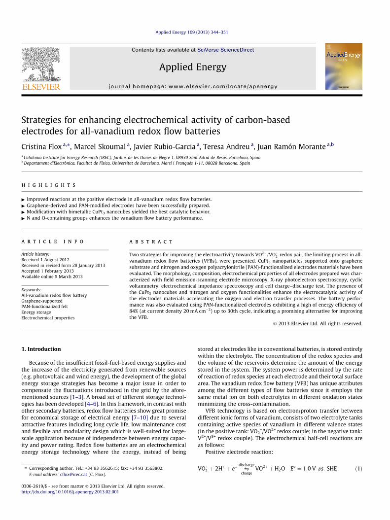
Fig. 4 shows the morphology observed by FESEM for theunmodified PAN and PAN-derived electrodes. Comparing the dPAN(400,24) electrode with the untreated one, no obvious change isobserved on the surface morphology. The same effect can be
es and FESEM images of CuPt3/HTGO.
30 nm
50 nm 30 nm 30 nm
50 nm 30 nm 50 nm
(a) (b) (c)
(e) (f) (d)
(g)
Fig. 4. FESEM images for (a) untreated PAN, (b) PAN (400,24), (c) PAN (500,6), (d) PAN (500,24), (e) PAN (500,36), (f) PAN (600,6) and (g) PAN (600,12) electrodes.
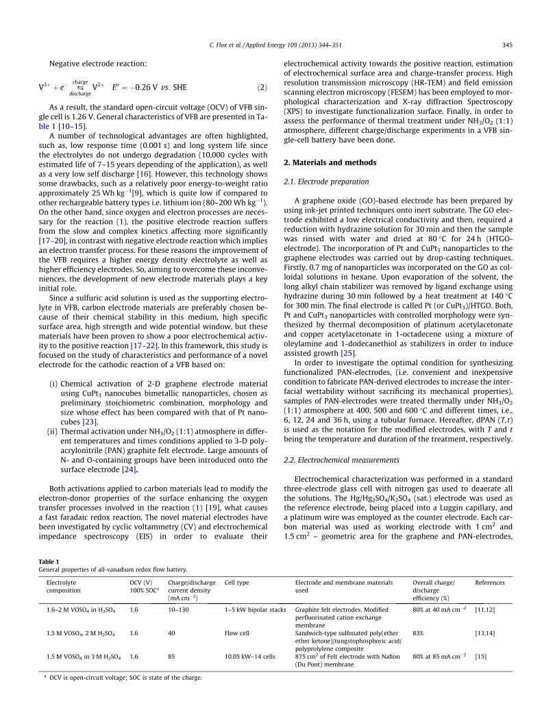
Fig. 5. Relationship between anodic peak current density obtained from CV with0.5 mol dm�3 VOSO4 solution in 3 mol dm�3 H2SO4 at scan rate 1 mV s�1 andtreated time of thermal activation for each temperature applied at untreatedelectrode (1), 400 �C (2), 500 �C (3) and 600 �C (4).
348 C. Flox et al. / Applied Energy 109 (2013) 344–351
observed with dPAN (500,6), but the surfaces of this electrode arecleaner than those of the untreated one. This phenomenon can becaused by the weak reaction between NH3 and graphite felt remov-ing the surface contaminants. However, the roughness surface in-creases treatment time from 6 to 36 h leading to small poresscattered which became larger and deeper because of the pressureof the NH3/O2 gas mixture on the fiber surface caused by longertreatments. Finally, when the dPAN material was obtained at600 �C for 6 h, the dPAN fibers underwent a clear deformation, asshown in Fig. 4f and longer treatment leads to a weakening ofthe graphite fiber mechanical properties (see Fig. 4g). Note thatthe dPAN (600,24) and dPAN (600,36) fibers have not been takeninto account because it would lead to reduce considerably theirelectric conductivity and to lower their mechanical properties.
The electrochemical parameters (i.e. anodic peak potential va-lue and current density) obtained from the CV at 1 mV s�1 havebeen represented in Figs. 5 and 6 as a function of all treatmentsin order to understanding of the optimal conditions for the thermalactivation treatment. As can be seen in Figs. 5 and 6, for all temper-atures of treatment, the anodic current density increases with timeof treatment until it attains the maximum value and afterwardsdisplays a downward trend with high time of treatment. The ano-dic current density approaches a maximum of 27.9, 37.1 and30.77 mA cm�2 for dPAN (400,24), dPAN (500,24) and dPAN(600,6) electrodes, respectively.
However, the anodic peak potential (Fig. 6) values approaches aminimum of 0.525 V (vs. Hg/Hg2SO4) for dPAN (400,24) and dPAN(500,24) and 0.528 V (vs. Hg/Hg2SO4) for dPAN (600,6), respec-tively. Low anodic peak potential is beneficial for improving theenergy storage efficiency because it implies a lower charge voltagefor VFB. It should be noticed that duration of treatment higher than6 h for temperature of 600 �C leads to significant reduction of elec-tric conductivity, and consequently present a poor electrocatalitycactivity towards reaction (1). For this reason, dPAN (600,24) anddPAN (600,36) electrodes have not been taken into account.
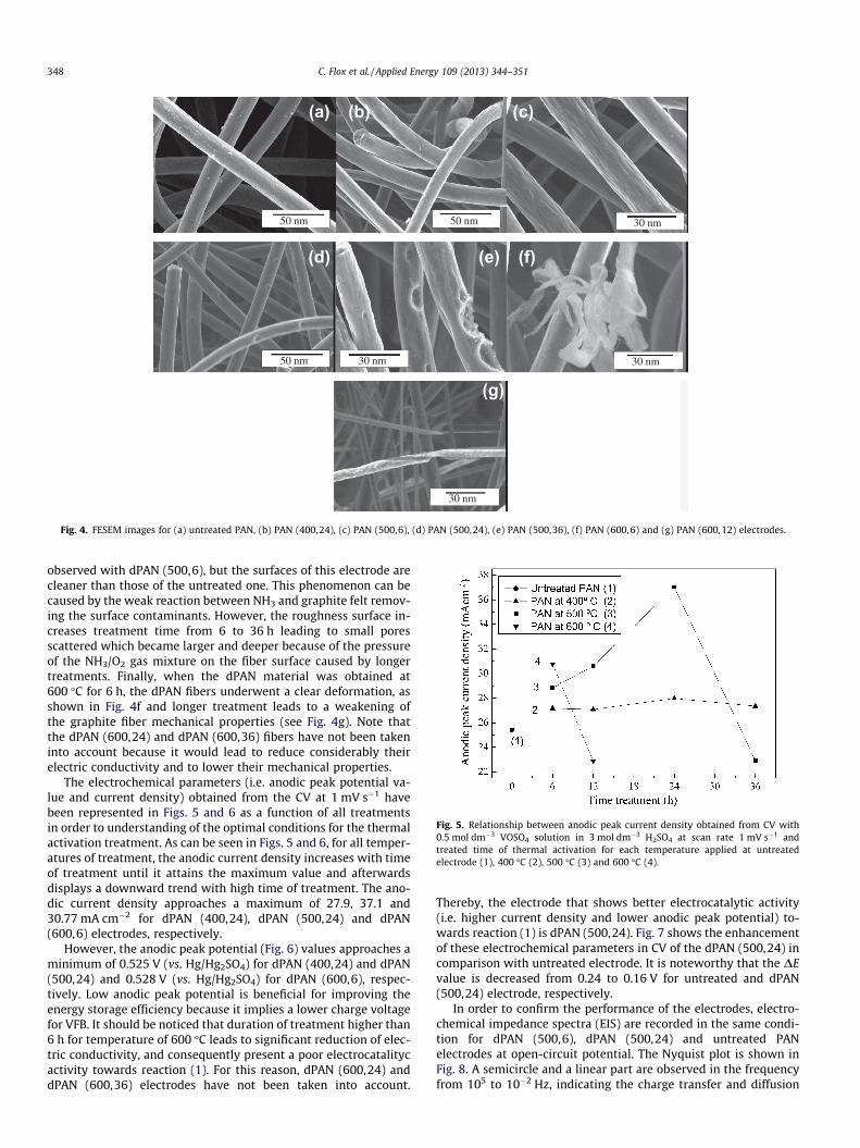
Thereby, the electrode that shows better electrocatalytic activity(i.e. higher current density and lower anodic peak potential) to-wards reaction (1) is dPAN (500,24). Fig. 7 shows the enhancementof these electrochemical parameters in CV of the dPAN (500,24) incomparison with untreated electrode. It is noteworthy that the DEvalue is decreased from 0.24 to 0.16 V for untreated and dPAN(500,24) electrode, respectively.
In order to confirm the performance of the electrodes, electro-chemical impedance spectra (EIS) are recorded in the same condi-tion for dPAN (500,6), dPAN (500,24) and untreated PANelectrodes at open-circuit potential. The Nyquist plot is shown inFig. 8. A semicircle and a linear part are observed in the frequencyfrom 105 to 10�2 Hz, indicating the charge transfer and diffusion
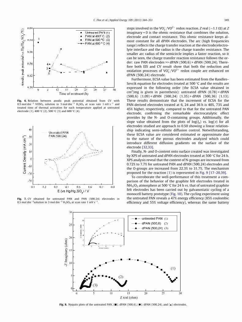
Fig. 6. Relation between anodic peak potential obtained from CV with0.5 mol dm�3 VOSO4 solution in 3 mol dm�3 H2SO4 at scan rate 1 mV s�1 andtreated time of thermal activation for each temperature applied at untreatedelectrode (1), 400 �C (2), 500 �C (3) and 600 �C (4).
Fig. 7. CV obtained for untreated PAN and PAN (500,24) electrodes in0.5 mol dm�3solution in 3 mol dm�3 H2SO4 at scan rate 1 mV s�1.
Fig. 8. Nyquits plots of the untreated PAN, (j); dPAN
C. Flox et al. / Applied Energy 109 (2013) 344–351 349
steps involved in the VOþ2 =VO2þ redox reaction. Z real (�1.1 X) at Zimaginary = 0 is the ohmic resistance that combines the solution,electrode and contact resistance. This ohmic resistance keeps al-most constant for all dPAN electrodes. The arc (high frequenciesrange) reflects the charge transfer reaction at the electrode/electro-lyte interface and the radius is the charge transfer resistance. Thesmaller arc radius of the semicircle implies a faster reaction, so itcan be seen, the charge transfer reaction resistance follows the or-der: raw PAN electrodes >> dPAN (500,6) > dPAN (500,24). There-fore both EIS and CV result show that both the reduction andoxidation processes of VOþ2 =VO2þ redox couple are enhanced ondPAN (500,24) electrode.
Furthermore, ECSA value has been estimated from the Randles–Sevcik equation for electrodes treated at 500 �C and the results areexpressed in the following order (the ECSA value obtained incm2/mg is given in parenthesis): untreated dPAN (0.78) < dPAN(500,6) (1.09) < dPAN (500,24) (1.35) > dPAN (500,36) (1.13).These results demonstrate that the increment of ECSA for thePAN-derived electrodes treated at 6, 24 and 36 h is 40%, 73% and45% higher, respectively, compared to that for the untreated PANelectrode, confirming the remarkable electrocatalytic effectprovides by the N- and O-containing groups. Additionally, theslope value obtained from the plots of log(Ip) vs. log(v) for allelectrodes studied are approach to 0.50 showing a linear relation-ship indicating semi-infinite diffusion control. Notwithstanding,these ECSA value are considered estimated or approximate dueto the nature of the porous electrodes analyzed which couldintroduce different diffusion gradients on the surface of theelectrode [32,33].
Finally, N- and O-content onto surface created was investigatedby XPS of untreated and dPAN electrodes treated at 500 �C for 24 h.XPS analysis reveal that the content of N-groups are increased from0.72% to 7.7% for untreated PAN and dPAN (500,24) electrodes andthe O-groups are increased from 22.3% to 31.7%. The mechanismproposed for the reaction (1) is represented in Fig. 9 [17–20,39].
To corroborate the well-performance of this treatment a com-parison of the behavior of the graphite felt electrodes treated inNH3/O2 atmosphere at 500 �C for 24 h vs. that of untreated graphitefelt electrodes has been carried out by galvanostatic cycling of amonocell battery prototype (Fig. 10). The cycling experiment usingthe untreated PAN reveals a 47% energy efficiency (85% coulombicefficiency and 55% voltage efficiency), whereas the same battery
(500,6), (d); dPAN (500,24), and (N) electrodes.

Fig. 9. Mechanism proposed of the O-containing groups towards the VO2þ=VOþ2redox couple.
Fig. 10. Charge–discharge cycling performance of a VFB assembled with (1)untreated PAN and (2) dPAN (500,24) electrodes.
Table 2Cycling performances on the VFB single-cell using dPAN (500, 24) electrodes.
Cycle index CE (%) VE (%) EE (%)
1st 98.99 85.02 84.162–10th 99.14 85.06 84.3310–20th 98.67 85.11 83.9820–30th 98.78 85.60 84.56
350 C. Flox et al. / Applied Energy 109 (2013) 344–351
hardware using the functionalized treated (500,24) graphite feltneared 84% energy efficiency (with near 99% coulombic efficiencyand 85% voltage efficiency) thus confirming this functionalizationtreatment as very promising for VFB batteries.
In order to assess the long-term stability of this electrodes, theircycling performance of the single-cell VFB using dPAN (500,24) elec-trodes was carried out for 30 cycles at 20 mA cm�2 from 0.8 V to1.9 V and the corresponding average efficiencies are given in Table 2.As can be seen, the treated electrode possesses higher stability andefficiency. It is noteworthy that the cell efficiencies achieved arecomparable, and even superior to efficiencies obtained by otherauthors [40–42]. Consequently, this functionalization treatmentbased on thermal treatment in NH3/O2 atmosphere is simple, envi-ronmental friendly, facile, cost-effective and very suitable forlarge-scale manufacture in comparison with other in the literature.
4. Conclusions
The enhancement of the electrochemical activity of the carbon-based electrodes towards VO2þ=VOþ2 reaction in all-VFB in sulfuric
medium has been successfully achieved by means of two strate-gies: (i) Graphene-decorated with CuPt3 nanoparticles and (ii)commercial polyacrilonytrile-felt treated at 500 �C in NH3/O2
(1:1) atmosphere (dPAN (500,24) electrode). These highly effectivestrategies accelerate the oxygen and electron transfer processes inthe electrode/electrolyte interface by the presence of O-containinggroups at surface of electrode showing good morphological proper-ties and large electrochemical surface area. Furthermore, the per-formance and longevity of the VFB single-cell prototype usingdPAN (500,24) electrode have been evaluated showing energy effi-ciency of 84% (85% of VE and 99% of CE) at a current density of20 mA cm�2 up to 30th cycles, leading to step forward in the VFBscale-up.
Acknowledgements
This research was supported by the European Regional Devel-opment Funds (ERDF, ‘‘FEDER Programa Competitivitat de Catalu-nya 2007-2013’’) and by the Ministerio de Economía yCompetitividad-INNPACTO, Project REDOX 2015 (IPT-2011-1690-920000), -CONSOLIDER Ingenio 2010, Project MULTICAT(CSD2009-00050) and NANO-EN ESTO Project MAT2010-21510.The research was supported by EIT and KIC-InnoEnergy underthe Project KIC-EES (33_2011_IP29_Electric Energy Storage).
References
[1] Barton JP, Infield DG. Energy storage and its use with intermittent renewableenergy. IEEE Trans Energy Convers 2004;19:441–8.
[2] Lund H. Large-scale integration of wind power into different energy systems.Energy 2005;30:2402–12.
[3] Landgrebe AR, Donley SW. Battery storage in residential applications of energyfrom photovoltaic sources. Appl Energy 1983;15:127–37.
[4] Xiong F, Zhou D, Xie Z, Chen Y. A study of the Ce3+/Ce4+ redox couple insulfamic acid for redox battery application. Appl Energy 2012;99:291–6.
[5] Shah R, Mithulananthan N, Bansal RC. Damping performance analysis ofbattery energy storage system, ultracapacitor and shunt capacitor with large-scale photovoltaic plants. Appl Energy 2012;36:235–44.
[6] Waag W, Käbitz S, Sauer DU. Experimental investigation of the lithium-ionbattery impedance characteristic at various conditions and aging states and itsinfluence on the application. Appl Energy 2013;102:885–97.
[7] Kim SU, Monroe CW. Increasing the rate capability of batteries with electrolyteflow. Appl Energy 2013;103:207–11.
[8] Kear G, Shah AA, Walsh FC. Development of the all-vanadium redox flowbattery for energy storage: a review of technological, financial and policyaspects. Int J Energy Res 2011. http://dx.doi.org/10.1002/er.
[9] Leung P, Li X, Ponce de Leon C, Berlouis L, John Low CT. Progress in redox flowbatteries, remaining challenges and their applications in energy storage. RSCAdv 2012;2:10125–56.
[10] Skyllas-Kazacos M, Chakrabarti MH, Hajimolana SA, Mjalli FS, Saleem M.Progress in flow battery research and development. J Electrochem Soc2011;158:R55–79.
[11] Skyllas-Kazacos M, Grossmith F. Efficient vanadium redox flow cell. JElectrochem Soc 1987;134:2950–3.
[12] Skyllas-Kazacos M, Kazacos G, Poon G, Verseema H. Recent advances withUNSW vanadium-based redox flow batteries. Int J Energy Res 2012;34:182–9.
[13] You D, Zhang H, Chen J. A simple model for the vanadium redox battery.Electrochim Acta 2009;54:6827–36.
[14] Jia C, Liu J, Yan Ch. A significantly improved membrane for vanadium redoxflow battery. J Power Sources 2010;195:4380–3.
[15] Zhao P, Zhang H, Zhou H, Chen J, Gao S, Yi B. Characteristics and performanceof 10 kW class all-vanadium redox-flow battery stack. J Power Sources2006;162:1416–20.
[16] Joerissen L, Garche J, Fabjan Ch, Tomazic G. Possible use of vanadium redox-flow batteries for energy storage in small grids and stand-alone photovoltaicsystems. J Power Sources 2004;127:98–104.
[17] Han P, Yue Y, Liu Z, Xu W, Zhang L, Xu H, et al. Graphene oxide nanosheets/multi-walled carbon nanotubes hybrid as an excellent electrocatalyticmaterial towards VO2þ=VOþ2 redox couples for vanadium redox flowbatteries. Energy Environ Sci 2011;4:4710–7.
[18] Li W, Liu J, Yan Ch. Multi-walled carbon nanotubes used as an electrodereaction catalyst for VO2þ=VOþ2 for a vanadium redox flow battery. Carbon2011;49:3463–70.
[19] Sun B, Skyllas-Kazacos M. Modification of graphite electrode materials forvanadium redox flow battery application—I. Thermal treatment. ElectrochimActa 1992;37:1253–60.

C. Flox et al. / Applied Energy 109 (2013) 344–351 351
[20] Sun B, Skyllas-Kazacos M. Chemical modification of graphite electrodematerials for vanadium redox flow battery application—Part II. Acidtreatments. Electrochim Acta 1992;37:2459–65.
[21] Wang WH, Wang XD. Investigation of Ir-modified carbon felt as the positiveelectrode of an all-vanadium redox flow battery. Electrochim Acta2007;52:6755–62.
[22] Li W, Liu J, Jan Ch. Graphite–graphite oxide composite electrode for vanadiumredox flow battery. Electrochim Acta 2011;56:5290–4.
[23] Flox C, Rubio-Garcia J, Nafria R, Zamani R, Skoumal M, Andreu T, et al.Active nano-CuPt3 electrocatalyst supported on graphene for enhancingreactions at the cathode in all-vanadium redox flow batteries. Carbon2012;50:2372–4.
[24] Flox C, Rubio-Garcia J, Skoumal M, Andreu T, Morante JR. PAN-based graphitefibers treatments based on NH3 for improved electrodes in vanadium redoxflow batteries. submitted for publication.
[25] Yang H, Dai L, Xu C, Fang J, Zou S. Electrooxidation of methanol and formic acidon PtCu nanoparticles. Electrochim Acta 2010;55:8000–4.
[26] Oriji G, Katayama Y, Miura T. Investigation on V(IV)/V(V) species in avanadium redox flow battery. Electrochim Acta 2004;49:3091–5.
[27] Salinas-Torres D, Huerta F, Montilla F, Morallón E. Study on electroactive andelectrocatalytic surfaces of single walled carbon nanotube-modifiedelectrodes. Electrochim Acta 2011;56:2464–70.
[28] Wang H, Qi B, Lu B, Bo X, Guo L. Comparative study on the electrocatalyticactivities of ordered mesoporous carbons and graphene. Electrochim Acta2011;56:3042–8.
[29] Hrapovic S, Liu Y, Male KB, Luong JHT. Electrochemical biosensing platformsusing platinum nanoparticles and carbon nanotubes. Anal Chem2004;76:1083–8.
[30] Li Ch, Yin X, Chen L, Li Q, Wang T. Porous carbon nanofibers derived fromconducting polymer: synthesis and application in lithium-ion batteries withhigh-rate capability. J Phys Chem C 2009;113:13438–42.
[31] Wu Y, Mao X, Cui X, Zhu L. Electroanalytical application of graphite nanofiberspaste electrode. Sens Actuators B 2010;145:749–55.
[32] Niquirilo RV, Teixeira-Neto E, Buzzo GS, Suffredini HB. Formic acid oxidation atPd, Pt and PbOx-based catalysts and calculation of their approximateelectrochemical active areas. Int J Electrochem Sci 2012;5:344–54.
[33] Lin R, Haung P, Ségalini J, Largeot C, Taberna PL, Chmiola J, et al. Solvent effecton the ion adsorption from ionic liquid electrolyte into sub-nanometer carbonpores. Electrochim Acta 2009;54:7025–32.
[34] Oriji G, Katayama Y, Miura T. Investigations on V(IV)/V(V) and V(II)/V(III)redox reactions by various electrochemical methods. J Power Sources2005;139:321–4.
[35] Dua V, Surwade SP, Ammu S, Agnihotra SR, Jain S, Roberts KE, et al. All-organicvapor sensor using inkjet-printed reduced graphene oxide. Angew Chem Int Ed2010;49:2154.
[36] Anderson AB, Neshev NM, Sidik RA, Shiller P. Mechanism for theelectrooxidation of water to OH and O bonded to platinum: quantumchemical theory. Electrochim Acta 2002;47:2999–3008.
[37] Page T, Johnson R, Hormes J, Noding S, Rambabu B. Study of methanol electro-oxidation reactions in carbon membrane electrodes and structural propertiesof Pt alloy electro-catalysts by EXAFS. J Electroanal Chem 2000;485:34–41.
[38] Xiong L, Manthiram A. Effect of atomic ordering on the catalytic activity ofcarbon supported PtM (M = Fe, Co., Ni, and Cu) alloys for oxygen reduction inPEMFCs. J Electrochem Soc 2005;152:A697–703.
[39] Gattrell M, Park J, MacDougall B, Apte J, McCarthy S, Wu CW. Study of themechanism of the V(IV)/V(V) redox reaction in acidic solutions. J ElectrochemSoc 2004;151:A123–30.
[40] Kim KJ, Kim YJ, Kim JH, Park MS. The effects of surface modification on carbonfelt electrodes for use in vanadium redox flow batteries. Mater Chem Phys2011;131:547–53.
[41] Yao C, Zhang H, Liu T, Li X, Liu Z. Carbon paper coated with supported tungstentrioxide as novel electrode for all-vanadium flow battery. J Power Sources2012;218:455–61.
[42] Yue L, Li W, Sun F, Zhao L, Xing L. Highly hydroxylated carbon fibres aselectrode materials of all-vanadium redox flow battery. Carbon2010;48:3079–90.