streetcar design criteria
TRANSCRIPT
KCMO Design Criteria Manual September 17, 2012 Group 1 Draft
Kansas City, Mo. Streetcar 1-1
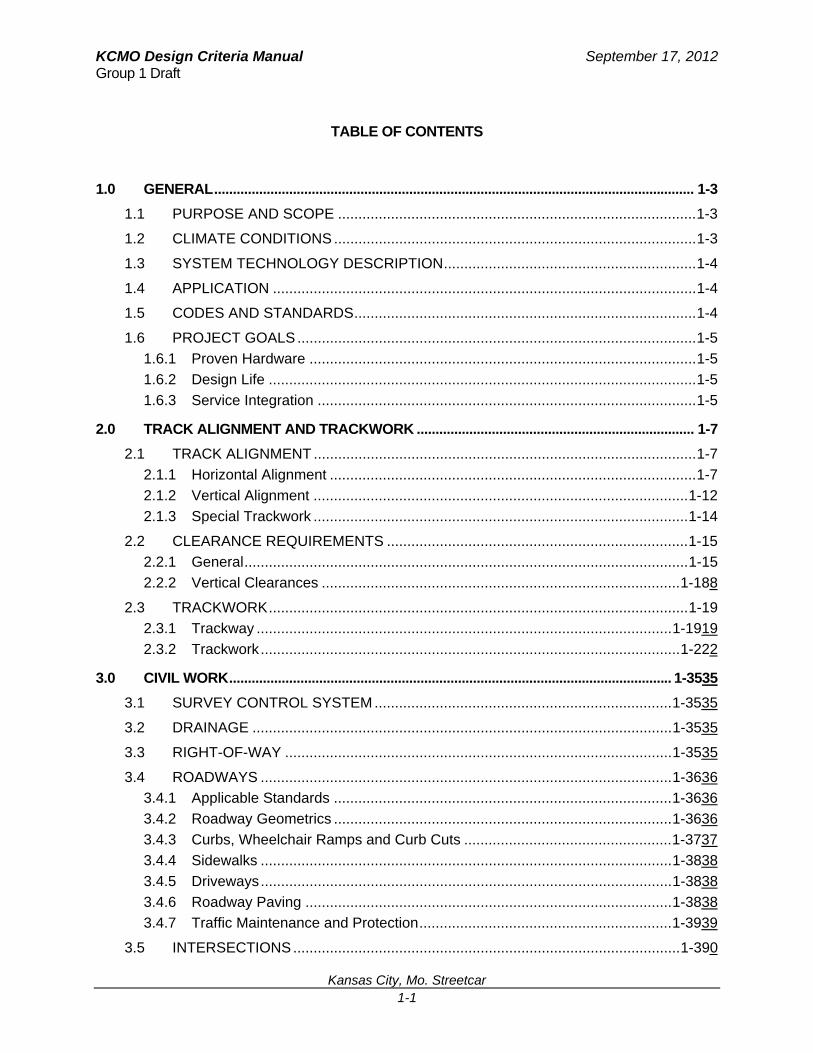
TABLE OF CONTENTS
1.0 GENERAL ................................................................................................................................ 1-3
1.1 PURPOSE AND SCOPE ........................................................................................ 1-3
1.2 CLIMATE CONDITIONS ......................................................................................... 1-3
1.3 SYSTEM TECHNOLOGY DESCRIPTION .............................................................. 1-4
1.4 APPLICATION ........................................................................................................ 1-4
1.5 CODES AND STANDARDS .................................................................................... 1-4
1.6 PROJECT GOALS .................................................................................................. 1-5
1.6.1 Proven Hardware ............................................................................................... 1-5
1.6.2 Design Life ......................................................................................................... 1-5
1.6.3 Service Integration ............................................................................................. 1-5
2.0 TRACK ALIGNMENT AND TRACKWORK .......................................................................... 1-7
2.1 TRACK ALIGNMENT .............................................................................................. 1-7
2.1.1 Horizontal Alignment .......................................................................................... 1-7
2.1.2 Vertical Alignment ............................................................................................ 1-12
2.1.3 Special Trackwork ............................................................................................ 1-14
2.2 CLEARANCE REQUIREMENTS .......................................................................... 1-15
2.2.1 General ............................................................................................................. 1-15
2.2.2 Vertical Clearances ........................................................................................ 1-188
2.3 TRACKWORK ....................................................................................................... 1-19
2.3.1 Trackway ...................................................................................................... 1-1919
2.3.2 Trackwork ....................................................................................................... 1-222
3.0 CIVIL WORK ...................................................................................................................... 1-3535
3.1 SURVEY CONTROL SYSTEM ......................................................................... 1-3535
3.2 DRAINAGE ....................................................................................................... 1-3535
3.3 RIGHT-OF-WAY ............................................................................................... 1-3535
3.4 ROADWAYS ..................................................................................................... 1-3636
3.4.1 Applicable Standards ................................................................................... 1-3636
3.4.2 Roadway Geometrics ................................................................................... 1-3636
3.4.3 Curbs, Wheelchair Ramps and Curb Cuts ................................................... 1-3737
3.4.4 Sidewalks ..................................................................................................... 1-3838
3.4.5 Driveways ..................................................................................................... 1-3838
3.4.6 Roadway Paving .......................................................................................... 1-3838
3.4.7 Traffic Maintenance and Protection .............................................................. 1-3939
3.5 INTERSECTIONS ............................................................................................... 1-390

KCMO Design Criteria Manual September 17, 2012 Group 1 Draft
Kansas City, Mo. Streetcar 1-2
3.6 PEDESTRIANS AND BICYCLISTS .................................................................... 1-400
6.0 STATION/STOP DESIGN ................................................................................................... 1-422
6.1 STREETCAR STOP DESIGN ............................................................................. 1-422
6.2 DIMENSIONS OF STOP ..................................................................................... 1-422
6.3 STOP SHELTER AND AMENITIES .................................................................... 1-433
6.4 STOP LOCATIONS, BICYCLE LANES, AND PARKING .................................... 1-433
Figure 12 – Streetcar Side Stop with Bike “bypass” ................................................. 1-4444
6.5 PUBLIC ART ..................................................................................................... 1-4545
KCMO Design Criteria Manual September 17, 2012 Group 1 Draft
Kansas City, Mo. Streetcar 1-3
1.0 GENERAL
1.1 Purpose and Scope The purpose of this manual is to establish the standards and guidelines for the engineering design and construction of the Kansas City Modern Streetcar system. The material contained herein is intended to provide a uniform basis for the design of any streetcar project that might be undertaken by the City of Kansas City Missouri (KCMO). Its purpose is to provide sufficient information to allow the development of preliminary and final designs including estimates of capital, operating and maintenance costs, and determination of the potential impacts of operations and construction on the communities.
The following design criteria provides the basis for uniform design and are not a substitute for engineering judgment and sound engineering practice that will be encountered during project development. It is the responsibility of the designer to expand upon the general framework of the design criteria to a level of detail consistent with the level of design. The designers are encouraged to analyze alternative approaches to solving design problems to determine the most cost-effective sustainable and environmentally sound solution.
This design criteria manual is to be used by designers to develop designs that meet the intent stated. In situations where deviations to the criteria are encountered, the designer is to submit a written waiver request to KCMO for approval of such deviations. Upon final submission of the Plans, Specifications, and Estimates, all deviations shall be approved by KCMO.
1.2 Climate Conditions The Kansas City metropolitan area is located in the Midwest United States and is 1,026 feet above sea level. Climate conditions can be varied; however, summer temperatures are warm with July being the hottest month and having an average high temperature of 90° Fahrenheit (F) and a record high of 113° F recorded on August 14, 1936. Also a couple days a year temperatures can surpass 100 degrees. As well, the metropolitan area has cold winters with January being the coldest month and having an average low temperature of 22° F and a record low of -23° F recorded on December 22, 1989.
Like typical Midwestern cities, the Kansas City metropolitan area is humid with four very different seasons. Moderate rainfall is very typical for the city with the majority coming in late spring and summer. In the colder months annual snowfall averages about 18.8” while ice storms can also be encountered. Kansas City is also home to tornadoes which typically occur during the spring. The city itself has not seen a tornado since the late 1800s, but the surrounding areas have more recently encountered devastating tornadoes.

KCMO Design Criteria Manual September 17, 2012 Group 1 Draft
Kansas City, Mo. Streetcar 1-4
1.3 System Technology Description Streetcar, for the purpose of the applicability of the criteria specified herein, denotes an urban transit system technology featuring electrically propelled modern articulated low floor vehicles that ride on steel wheels that run along steel rails, and utilize power drawn from an overhead wire (or off-wire and powered by on board energy storage) to travel along both city streets (Mixed-traffic or Non-Exclusive Right-of-Way) and dedicated rights-of-way with street crossing (Semi-Exclusive Right-of-Way).
1.4 Application The material contained in the following chapters provides a uniform basis for design and is expected to be refined and expanded during preliminary engineering and final design.
This design criteria manual represents a recommended set of uniform and minimum guidelines for use in the development, design, engineering, and implementation of the streetcar project. It is not a specification and therefore, the following criteria are intended to set minimum guidelines to assure design uniformity and consistency of systems, components, and facilities of streetcar infrastructure.
These criteria serve as guidelines and do not substitute for engineering judgment and sound engineering practice. More detailed design criteria not deemed broad enough for this manual can be included in the Basis of Design Report by the design consultant(s) but must still adhere to the design criteria contained herein. Specific exceptions may apply in special cases. The designers are responsible for identifying any necessary departure from the criteria contained in this document, and then notifying the KCMO’s project manager. Any exceptions from or changes to the criteria must be reviewed and approved by KCMO prior to use in the design. Applications for change in criteria, additions to the criteria, and other questions will be submitted in writing.
The criteria manual may periodically require revisions to reflect changes in environment, industry, engineering, operation, and maintenance, or to reflect policy changes.
1.5 Codes and Standards In general, codes, criteria, and standards that are promulgated by third parties and regulatory agencies and that are applicable to the design of KCMO-owned facilities are identified in each chapter of the manual. Unless stated otherwise, designers shall verify that they are working with the most recent editions of such documents.
Where facilities that are constructed under a KCMO project will be owned and/or maintained by others, the designer shall verify what criteria that entity may require and obtain same including published criteria, applicable standard drawings, directives, manuals, specifications, as well as any revisions thereto. The designer must keep such criteria up-to-date during the entire design phase of the project.
KCMO Design Criteria Manual September 17, 2012 Group 1 Draft
Kansas City, Mo. Streetcar 1-5
1.6 Project Goals The primary goal of a streetcar project is to provide passengers with the benefits of improved public transportation service in a safe, cost-effective, environmentally sensitive and socially responsible manner. To this end, the following policies shall be adhered to:
1.6.1 Proven Hardware The streetcar system shall be designed to use proven subsystems hardware and design concepts. All of the major subsystems, such as vehicles, signaling and traction power equipment, shall be supplied by established manufacturers, have a documented operating history of previous and current usage, and be available off the shelf, so far as practicable. The same requirements shall apply to spare parts. Waiver of these requirements shall be considered only where the alternative subsystem offers substantial technical and cost advantages, is in an advanced state of development and has accumulated substantial test data under near-revenue conditions.
Streetcar procurement is through a competitive bidding by established manufacturers of transportation equipment or through procurement options from other streetcar operating agencies.
1.6.2 Design Life The streetcar system's fixed facilities (structures and buildings) shall be designed for continued operation over a minimum period of 50 years before complete refurbishment and renovations are necessary due to wear and tear and obsolescence.
Major fixed system equipment (such as substation gear, shop machinery, and streetcar vehicles) shall be designed for a minimum of 30 years before complete replacement becomes necessary, assuming that approved maintenance policies are followed.
1.6.3 Service Integration The streetcar route is to be part of the overall local and regional transportation system. Specific provisions shall be made for the efficient interchange of passengers with private and other public transportation modes.

KCMO Design Criteria Manual September 17, 2012 Group 1 Draft
Kansas City, Mo. Streetcar 1-6
THIS PAGE INTENTIONALLY LEFT BLANK
KCMO Design Criteria Manual September 17, 2012 Group 1 Draft
Kansas City, Mo. Streetcar 1-7
2.0 TRACK ALIGNMENT AND TRACKWORK This chapter establishes the basic track geometry and clearance criteria to be used in the design of the streetcar project.
Except for the requirements established in these criteria and KCMO drafting standards, all geometry and clearances shall follow the AREMA Manual for Railway Engineering and Portfolio of Track Work Plans, “The Track Design Handbook for Light Rail Transit” TCRP Report 155 sponsored by the Federal Transit Administration, and the APTA Guidelines for Design of Rapid Transit Facilities modified as necessary to reflect the physical requirements and operating characteristics of the streetcar project.
2.1 Track Alignment 2.1.1 Horizontal Alignment Horizontal curvature and super-elevation shall be related to design speed and the acceleration and deceleration characteristics of the design vehicle. The streetcar includes at-grade segments where vehicles will operate on a shared right-of-way with vehicular traffic within local and arterial streets. The track alignment shall be designed to accommodate a maximum design speed according to the following criteria:
Tangent track – Posted speed (+/- 30 MPH)
Lane shift through intersection – Approximately 15 MPH
90 degree turn – Approximately 5-10 MPH
The design speed shall take into account the spacing of stops, location of curves, curve radius, construction limitations, and the performance characteristics of the design vehicle. Geometry constraints will prevent the optimum design speed from being achieved at some locations. The track designer shall provide a speed gradient table describing or illustrating the different design speeds throughout the alignment.
2.1.1.1 Horizontal Tangents The following criteria provide minimum lengths of horizontal tangent track for a variety of scenarios.
Curves, Switches, Special Trackwork, and Stop Platforms The minimum length of horizontal tangent track between curved sections, preceding a point of switch, special trackwork, or stop platform shall be as follows:
KCMO Design Criteria Manual September 17, 2012 Group 1 Draft
Kansas City, Mo. Streetcar 1-8
Broken Back Curves Condition Tangent Length
Absolute Minimum 3 times the design speed in mph
Reverse Condition Tangent Length
Desirable 40 feet
Absolute Minimum* 0 feet
Compound Curves Condition Tangent Length
Absolute Minimum 0 feet
Special Trackwork Condition Tangent Length
Absolute Minimum 10 feet
Stop Platform Condition Tangent Length
Desirable Minimum 45** ft beyond platform ends
* Values below the desirable minimum condition require prior written approval from KCMO.
** Designer to submit clearance calculations and figures for approval for all tangents less than 45 feet from the edge of platform
If adjacent broken back curves in the same direction, which are in close proximity to one another, cannot be replaced by a single simple curve due to geometric constraints, a series of compound curves with combining spirals shall be the preferred arrangement. Broken back curves, (e.g., short tangents between curves in the same direction) shall be avoided whenever possible.
All special trackwork shall be located on a horizontal tangent and the associated points of switches/frog heels shall be located an absolute minimum distance of 10 feet from a point of horizontal curvature.
At stop platforms, the horizontal alignment shall be tangent throughout the entire length of the platform. The tangent track shall also be extended beyond both ends of the platform by a desired minimum distance of 45 feet so that the streetcar clearance envelope does not overhang any portion of the platform as the streetcar approaches and leaves the stop. If the tangent cannot be extended 45 feet from the platform ends, the clearances between the platform and the vehicle inswing and outswing shall be checked to provide the minimum required clearance between the vehicle and the platform structure. For tangents less than 45 feet beyond the platform ends, the designer shall submit a variance which includes a graphic illustrating the clearance check for KCMO approval.
If platforms must be located on curved track, the designer is required to perform a detailed investigation of clearances and possible hazardous conditions, with consideration given to methods for keeping patrons clear of the streetcar’s dynamic envelope overhang when entering and leaving the stop.
KCMO Design Criteria Manual September 17, 2012 Group 1 Draft
Kansas City, Mo. Streetcar 1-9
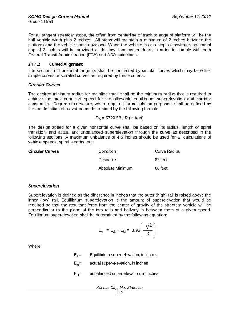
For all tangent streetcar stops, the offset from centerline of track to edge of platform will be the half vehicle width plus 2 inches. All stops will maintain a minimum of 2 inches between the platform and the vehicle static envelope. When the vehicle is at a stop, a maximum horizontal gap of 3 inches will be provided at the low floor center doors in order to comply with both Federal Transit Administration (FTA) and ADA guidelines.
2.1.1.2 Curved Alignment Intersections of horizontal tangents shall be connected by circular curves which may be either simple curves or spiraled curves as required by these criteria.
Circular Curves
The desired minimum radius for mainline track shall be the minimum radius that is required to achieve the maximum civil speed for the allowable equilibrium superelevation and corridor constraints. Degree of curvature, where required for calculation purposes, shall be defined by the arc definition of curvature as determined by the following formula:
DA = 5729.58 / R (in feet)
The design speed for a given horizontal curve shall be based on its radius, length of spiral transition, and actual and unbalanced superelevation through the curve as described in the following sections. A maximum unbalance of 4.5 inches should be used for all calculations of vehicle speeds, spiral lengths, etc.
Circular Curves Condition Curve Radius
Desirable 82 feet
Absolute Minimum 66 feet
Superelevation
Superelevation is defined as the difference in inches that the outer (high) rail is raised above the inner (low) rail. Equilibrium superelevation is the amount of superelevation that would be required so that the resultant force from the center of gravity of the streetcar vehicle will be perpendicular to the plane of the two rails and halfway in between them at a given speed. Equilibrium superelevation shall be determined by the following equation:
Eq = Ea + Eu = 3.96
R
2 V
Where:
Eq = Equilibrium super-elevation, in inches
Ea = actual super-elevation, in inches
Eu = unbalanced super-elevation, in inches
KCMO Design Criteria Manual September 17, 2012 Group 1 Draft
Kansas City, Mo. Streetcar 1-10
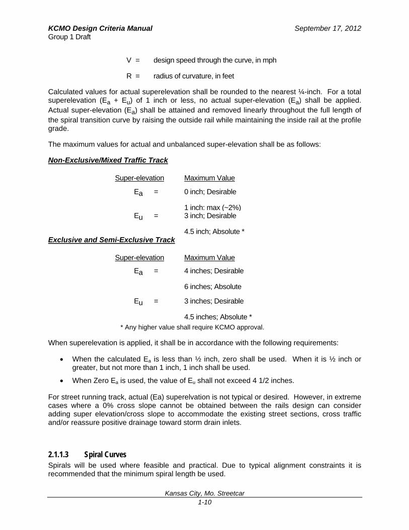
V = design speed through the curve, in mph
R = radius of curvature, in feet
Calculated values for actual superelevation shall be rounded to the nearest ¼-inch. For a total superelevation (Ea + Eu) of 1 inch or less, no actual super-elevation (Ea) shall be applied. Actual super-elevation (Ea) shall be attained and removed linearly throughout the full length of the spiral transition curve by raising the outside rail while maintaining the inside rail at the profile grade.
The maximum values for actual and unbalanced super-elevation shall be as follows:
Non-Exclusive/Mixed Traffic Track
Super-elevation Maximum Value
Ea = 0 inch; Desirable
1 inch: max (~2%)Eu = 3 inch; Desirable
4.5 inch; Absolute *Exclusive and Semi-Exclusive Track
Super-elevation Maximum Value
Ea = 4 inches; Desirable
6 inches; Absolute
Eu = 3 inches; Desirable
4.5 inches; Absolute * * Any higher value shall require KCMO approval.
When superelevation is applied, it shall be in accordance with the following requirements:
When the calculated Ea is less than ½ inch, zero shall be used. When it is ½ inch or greater, but not more than 1 inch, 1 inch shall be used.
When Zero Ea is used, the value of Eu shall not exceed 4 1/2 inches.
For street running track, actual (Ea) superelvation is not typical or desired. However, in extreme cases where a 0% cross slope cannot be obtained between the rails design can consider adding super elevation/cross slope to accommodate the existing street sections, cross traffic and/or reassure positive drainage toward storm drain inlets.
2.1.1.3 Spiral Curves Spirals will be used where feasible and practical. Due to typical alignment constraints it is recommended that the minimum spiral length be used.
KCMO Design Criteria Manual September 17, 2012 Group 1 Draft
Kansas City, Mo. Streetcar 1-11
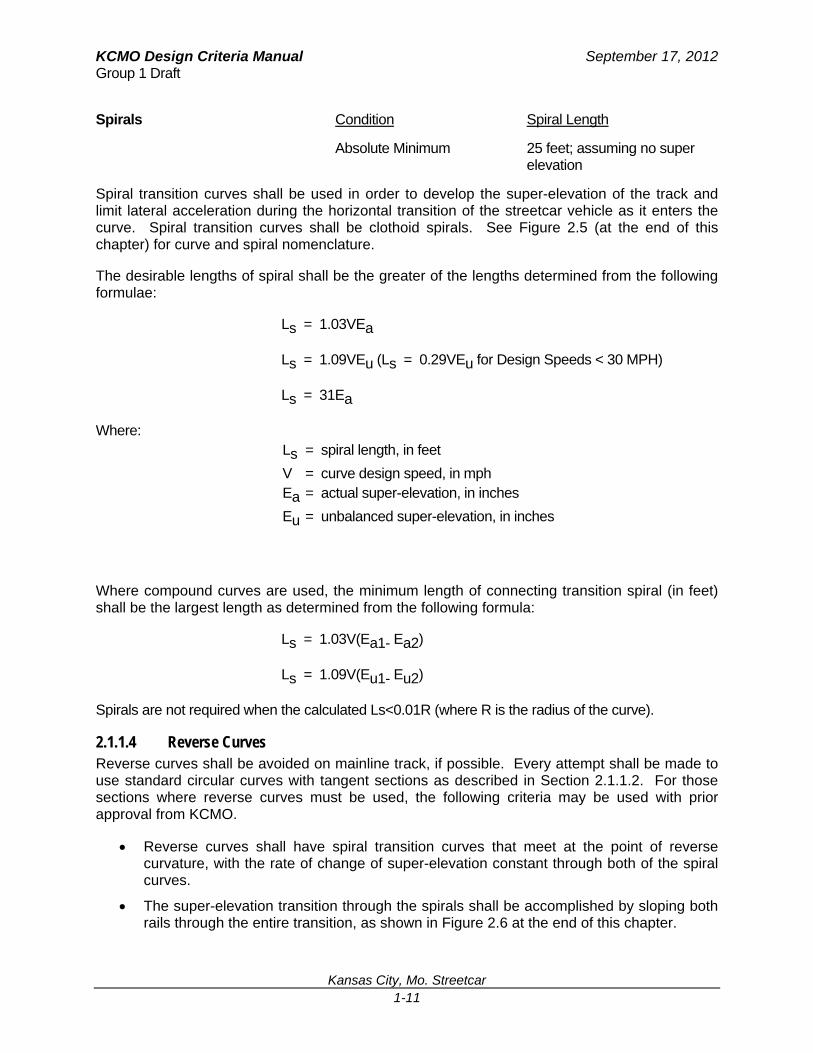
Spirals Condition Spiral Length
Absolute Minimum 25 feet; assuming no super elevation
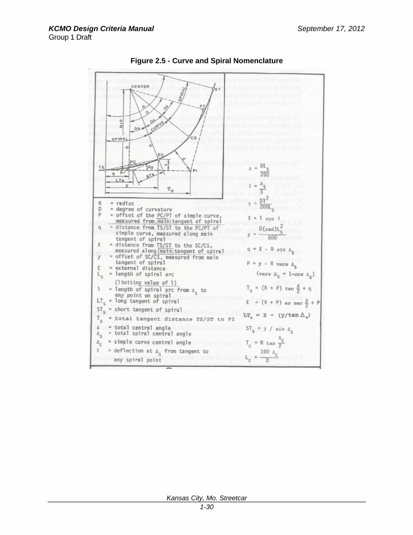
Spiral transition curves shall be used in order to develop the super-elevation of the track and limit lateral acceleration during the horizontal transition of the streetcar vehicle as it enters the curve. Spiral transition curves shall be clothoid spirals. See Figure 2.5 (at the end of this chapter) for curve and spiral nomenclature.
The desirable lengths of spiral shall be the greater of the lengths determined from the following formulae:
Ls = 1.03VEa
Ls = 1.09VEu (Ls = 0.29VEu for Design Speeds < 30 MPH)
Ls = 31Ea
Where: Ls = spiral length, in feet
V = curve design speed, in mph Ea = actual super-elevation, in inches
Eu = unbalanced super-elevation, in inches
Where compound curves are used, the minimum length of connecting transition spiral (in feet) shall be the largest length as determined from the following formula:
Ls = 1.03V(Ea1- Ea2)
Ls = 1.09V(Eu1- Eu2)
Spirals are not required when the calculated Ls<0.01R (where R is the radius of the curve).
2.1.1.4 Reverse Curves Reverse curves shall be avoided on mainline track, if possible. Every attempt shall be made to use standard circular curves with tangent sections as described in Section 2.1.1.2. For those sections where reverse curves must be used, the following criteria may be used with prior approval from KCMO.
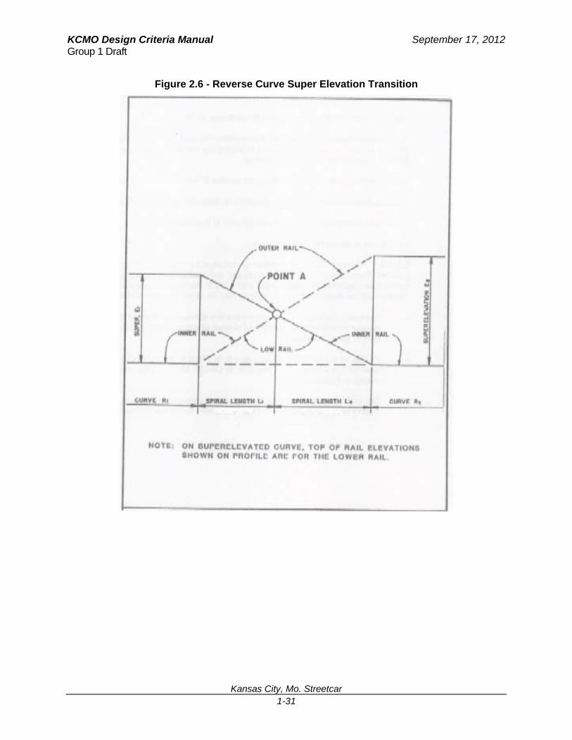
Reverse curves shall have spiral transition curves that meet at the point of reverse curvature, with the rate of change of super-elevation constant through both of the spiral curves.
The super-elevation transition through the spirals shall be accomplished by sloping both rails through the entire transition, as shown in Figure 2.6 at the end of this chapter.

KCMO Design Criteria Manual September 17, 2012 Group 1 Draft
Kansas City, Mo. Streetcar 1-12
2.1.2 Vertical Alignment The vertical track alignment shall be composed of constant grade tangent segments connected at their intersection by parabolic curves having a constant rate of change in grade. The profile grade line in tangent track shall be along the centerline of track between the two running rails and in the plane defined by the top of the two rails. In curved track, the inside rail of the curve shall remain at the profile grade line and super-elevation achieved by raising the outer rail above the inner rail.
2.1.2.1 Vertical Tangents The minimum length of constant profile grade between vertical curves shall be as follows:
Between Curves Condition Tangent Length
Absolute Minimum 0 ft
Special Trackwork Condition Tangent Length
Absolute Minimum 10 ft
Stop Platform Condition Tangent Length
Absolute Minimum 5 feet beyond the front and rear axles when vehicle is in the stop position at the platform
All special trackwork shall be located on tangent grade and the associated points of switches/frog heels shall be located a minimum distance of 10 feet from the point of vertical curvature.
At streetcar stop platforms, the vertical alignment shall be tangent throughout the entire length of the platform. The tangent grade shall extend an absolute minimum distance of 5 feet beyond both the front and rear vehicle axles when the vehicle is stopped at the platform. If platforms are located on curved track, the designer is required to perform a detailed investigation of clearances and possible hazardous conditions, with consideration being given to methods of keeping the height of the stop platform a reasonable distance below or above the height of the streetcar door. Stop indicators for the streetcar at the stop platform must be shown on civil plans.
KCMO Design Criteria Manual September 17, 2012 Group 1 Draft
Kansas City, Mo. Streetcar 1-13
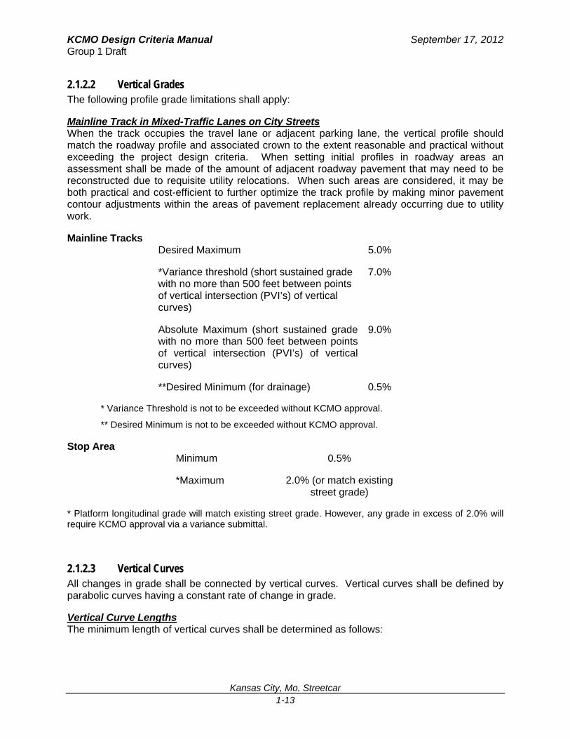
2.1.2.2 Vertical Grades The following profile grade limitations shall apply:
Mainline Track in Mixed-Traffic Lanes on City Streets When the track occupies the travel lane or adjacent parking lane, the vertical profile should match the roadway profile and associated crown to the extent reasonable and practical without exceeding the project design criteria. When setting initial profiles in roadway areas an assessment shall be made of the amount of adjacent roadway pavement that may need to be reconstructed due to requisite utility relocations. When such areas are considered, it may be both practical and cost-efficient to further optimize the track profile by making minor pavement contour adjustments within the areas of pavement replacement already occurring due to utility work.
Mainline Tracks Desired Maximum 5.0%
*Variance threshold (short sustained grade with no more than 500 feet between points of vertical intersection (PVI’s) of vertical curves)
7.0%
Absolute Maximum (short sustained grade with no more than 500 feet between points of vertical intersection (PVI’s) of vertical curves)
9.0%
**Desired Minimum (for drainage) 0.5%
* Variance Threshold is not to be exceeded without KCMO approval.
** Desired Minimum is not to be exceeded without KCMO approval.
Stop Area Minimum 0.5%
*Maximum 2.0% (or match existing street grade)
* Platform longitudinal grade will match existing street grade. However, any grade in excess of 2.0% will require KCMO approval via a variance submittal.
2.1.2.3 Vertical Curves All changes in grade shall be connected by vertical curves. Vertical curves shall be defined by parabolic curves having a constant rate of change in grade.
Vertical Curve Lengths The minimum length of vertical curves shall be determined as follows:
KCMO Design Criteria Manual September 17, 2012 Group 1 Draft
Kansas City, Mo. Streetcar 1-14
Crest curves: LVC =
Sag curves: LVC =
Where:
LVC = length of vertical curve, in feet
A = (G2 - G1) = algebraic difference in gradients connected by the vertical curve, in percent
G1 = percent grade of approaching tangent
G2 = percent grade of departing tangent
V = design speed, in mph
The rate of change (K value) for vertical curves should not be less than 8.2 for sag curves and 8.2 for crest curves, where K = LVC/A. The minimum “K Values” must be verified and should be adjusted to the vehicle manufacturer’s actual K values once the vehicle is selected. Actual values should be documented and submitted as a design criteria revision request for KCMO approval.
If a vertical curve with a K value less than 16.4 is combined with a horizontal curve with a radius less than 95 feet, the designer shall consult the vehicle manufacturer to ensure that the vehicle can negotiate the proposed geometry.
The minimum sag equivalent radius of curvature for vertical curves located on mainline tangent track shall not be less than 820 feet (verify once final vehicle is selected). The equivalent radius of curvature can be calculated from the following formula:
Rv = )(01.0
LVC
12 GG
2.1.3 Special Trackwork In general, special trackwork shall be located on track segments that are tangent both horizontally and vertically, including tangent segments in advance of points of switches. For alignment requirements through special trackwork areas, refer to Section 2.3.2, Trackwork.
KCMO Design Criteria Manual September 17, 2012 Group 1 Draft
Kansas City, Mo. Streetcar 1-15
2.2 Clearance Requirements 2.2.1 General This section establishes the minimum dimensions required to assure proper clearances between the streetcar vehicles or transit structures and wayside obstructions involved. Vehicle preference will not be established in this document.
2.2.1.1 Vehicle Dynamic Envelope
Vehicle Description To allow the design of fixed facilities to proceed prior to the selection of a specific streetcar, a composite design vehicle has been established based on the most critical vehicle dimensions and operational characteristics of the vehicles under consideration by KCMO. The clearance criteria defined in this section is intended to provide latitude in selecting a streetcar system for the present and for future selection of replacement vehicle technology.
Static Outline The static dimensions of the composite streetcar may include mirrors on each side toward the end of the vehicle. This information will be provided by the vehicle manufacturer. The mirrors are assumed to extend a maximum of 6 inches outside of the normal static vehicle envelope.
Dynamic Outline The dynamic outline of the composite streetcar includes the anticipated dynamic movement of the vehicle during operation and factors to account for wear of both vehicle and track components during the life of the system. The major factors which affect the dynamic outline consist of the following:
Lateral roll of the vehicle
Primary and secondary suspension failure
Vehicle body yaw
Lateral play in the wheels
Rail wear and wheel flange wear
Vehicle manufacturer’s tolerances
The actual extents to which these factors affect the total dynamic envelope are based on the specific vehicle selected and are only approximate.
2.2.1.2 Track Curvature and Superelevation Adjustment When a streetcar vehicle enters a horizontal curve, including turnouts, the dynamic outline must be adjusted for overhang at the end of the vehicle and for middle ordinate shift (belly-in) midway between the trucks (bogies) of the vehicles. The presence of superelevation shall increase the middle ordinate shift particularly toward the top of the vehicle. Once the final vehicle selection is made, designer shall obtain vehicle dynamic envelope tables from vehicle supplier or consultant and use for design.
KCMO Design Criteria Manual September 17, 2012 Group 1 Draft
Kansas City, Mo. Streetcar 1-16
Turnouts When a streetcar vehicle travels through the diverging route of a turnout the dynamic outline shall be affected. During preliminary design, the dynamic outline shall be checked adjacent to, and 45 feet beyond, all curved components (switches, closure rails) of the diverging turnout route in order to determine potential conflicts with adjacent structures, poles, etc.
Mirrors For clearance requirements, mirrors should be considered for tangent track and for the outside of all curves. Mirrors shall not be considered for the inside of curves when the car body mid-ordinate exceeds the mirror mid-ordinate. See also section 2.2.1.1, “Static Outline.”
Horizontal Clearances All existing and proposed structures, including OCS poles, bridge pier columns, and retaining walls shall clear the total streetcar dynamic outline as defined in Section 2.2.1.1, by a distance equal to or greater than the sum of applicable clearances and tolerances defined in this section.
Clearances shall be checked between the streetcar dynamic outline and all adjacent structures along tangent track and at turnouts a minimum of 45 feet in either direction of the structures. This is to verify that an adjacent curved track does not affect the clearance in the adjoining tangent section.
General Horizontal Clearances:
Rigid objects (i.e., retaining wall): Design variances for areas that do not conform to design criteria will require KCMO approval.
Adjacent traffic lanes: Only the static envelope will be used for non-rigid objects such as traffic lanes and striping.
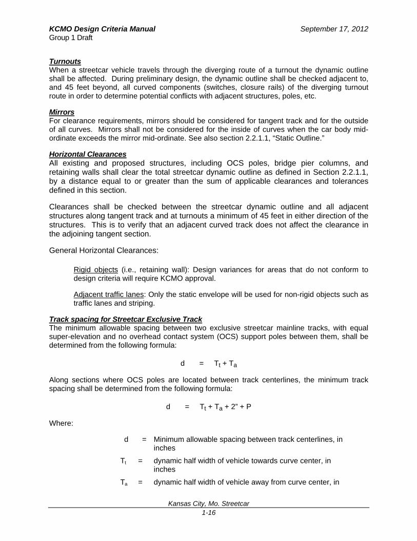
Track spacing for Streetcar Exclusive Track The minimum allowable spacing between two exclusive streetcar mainline tracks, with equal super-elevation and no overhead contact system (OCS) support poles between them, shall be determined from the following formula:
d = Tt + Ta
Along sections where OCS poles are located between track centerlines, the minimum track spacing shall be determined from the following formula:
d = Tt + Ta + 2” + P
Where:
d = Minimum allowable spacing between track centerlines, in inches
Tt = dynamic half width of vehicle towards curve center, in inches
Ta = dynamic half width of vehicle away from curve center, in

KCMO Design Criteria Manual September 17, 2012 Group 1 Draft
Kansas City, Mo. Streetcar 1-17
inches
P = Maximum allowable OCS pole diameter (including deflection) of 18.5 inches
Clearance to Obstructions The distance between any fixed object along the trackway and the centerline of track shall be equal to the design envelope as defined in the formula below:
Design envelope* = (dynamic outline) + (running clearance) +
(construction and maintenance tolerances)
Acoustic treatments shall be considered part of a structure. Allow 3" for acoustic treatment.
Exceptions to the design envelope requirements are listed in Section 2.2.1.3
Running Clearances The running clearance provides clear passage for a vehicle which has moved to the extreme position within the dynamic outline. Design running clearances for exclusive streetcar track shall be:
4" for poles and structural supports
2" for all other permanent structures
Construction Tolerances Along Proposed Structures A construction tolerance is required when a new structure is constructed adjacent to or above the streetcar. This tolerance is added to the base construction and maintenance tolerance and applies to construction that is part of the streetcar project or future construction. This construction tolerance is provided in the event that the structure, or part thereof, is mis-located during construction. These clearances shall be:
6" for Soldier Pile and Lagging Walls
2" for other proposed structures
Track Construction and Maintenance Tolerances Track construction and maintenance tolerances account for a combination of factors such as track misalignment, wheel and track gauge tolerances, and wheel and rail wear. These tolerances also include provision for any cross level variances between the track rails due to unintentional construction inaccuracies and possible deference of track maintenance during operation of the system. The following track construction and maintenance tolerances apply:
Direct fixation or embedded track ½ inch
Mainline tie and ballast track 3 inches
Special Trackwork ½ inch
Yard track 3 inches

KCMO Design Criteria Manual September 17, 2012 Group 1 Draft
Kansas City, Mo. Streetcar 1-18
2.2.1.3 Vehicle Interface at Stop Platforms At passenger stops, the distance from the centerline of the track to the edge of platform shall be 50 inches with a tolerance of plus 0.5 inch and minus 0.0 inch for tangent track.
2.2.1.4 Maintenance and Emergency Evacuation Paths A minimum clear width of 30 inches shall be provided between the static envelope and any continuous obstruction alongside the track to create a walkway for maintenance personnel and to create a designated passenger emergency evacuation path.
This space shall be provided in areas of restricted right of way, in areas of retained cut, and on structures. The space should be reasonably level.
2.2.2 Vertical Clearances Since the streetcar system will draw electric traction power from an overhead contact wire system, provide the following vertical clearances from the top of the high rail along any given section of track to the underside of any overhead structure, within the horizontal limits of the clearance envelope:
Non-Exclusive/Mixed Traffic Track
Exclusive/Semi-Exclusive Track
Desirable Minimum
19 ft - 0 in 15 ft - 0 in
*Absolute Minimum
18 ft - 6 in **14 ft - 0 in
* Any value less than the Desirable Minimum requires KCMO approval.
** To be verified with vehicle manufacturer
Vertical clearances less than the absolute minimum may not be used without specific approval of KCMO.
Transit structures over public highways shall be in accordance with American Association of State Highway and Transportation Officials (AASHTO) Standard Specifications for Highway Bridges or as modified by KCMO or local jurisdiction, whichever is applicable. Vertical clearances for transit structures over local public streets and roads shall be as required by the authority having jurisdiction over the street or road.
The National Electrical Safety Code (NESC) stipulates minimum distances between the streetcar wire and the rail in various situations. Civil and structural designers shall coordinate their design related to any structures over the tracks to ensure that NESC and other OCS design criteria are met.
KCMO Design Criteria Manual September 17, 2012 Group 1 Draft
Kansas City, Mo. Streetcar 1-19
2.3 Trackwork 2.3.1 Trackway Trackway is defined as that portion of the streetcar line which has been prepared to support the track and its appurtenant structures.
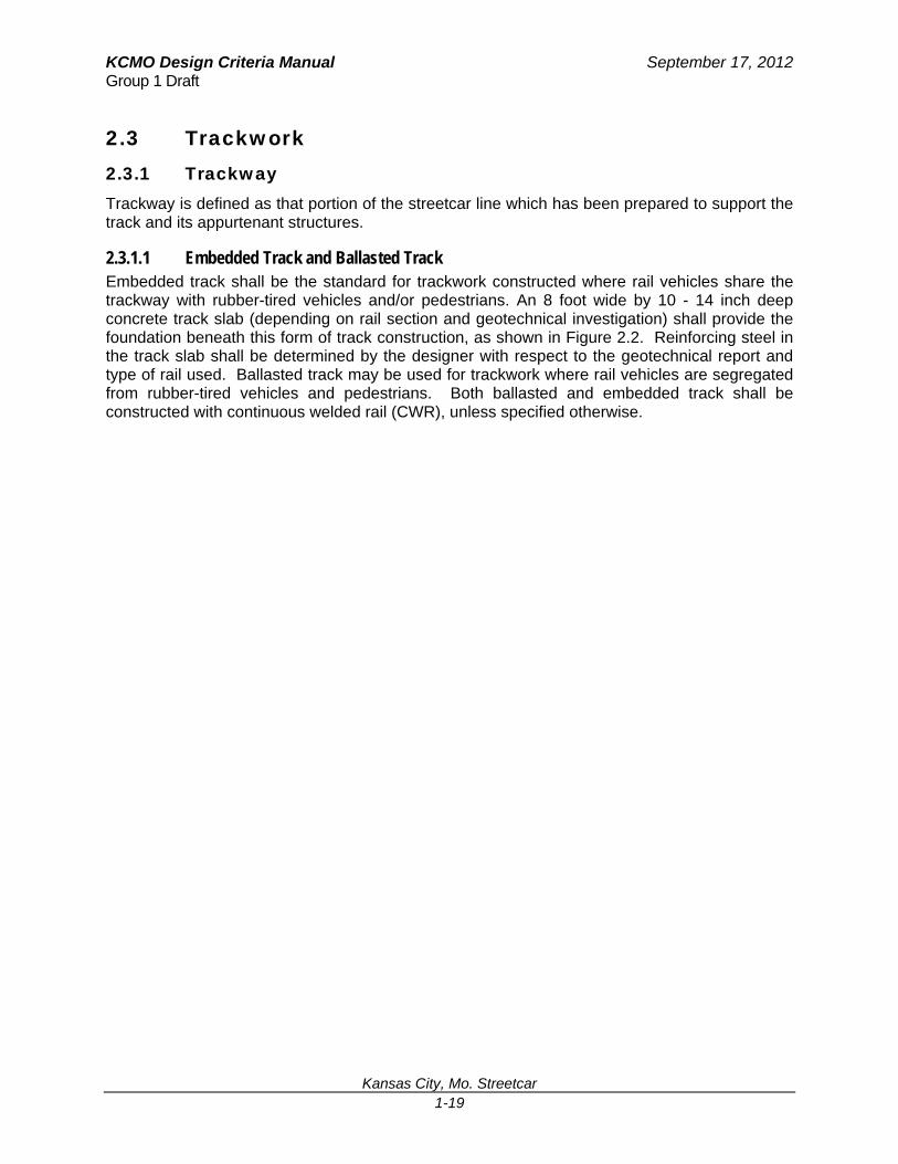
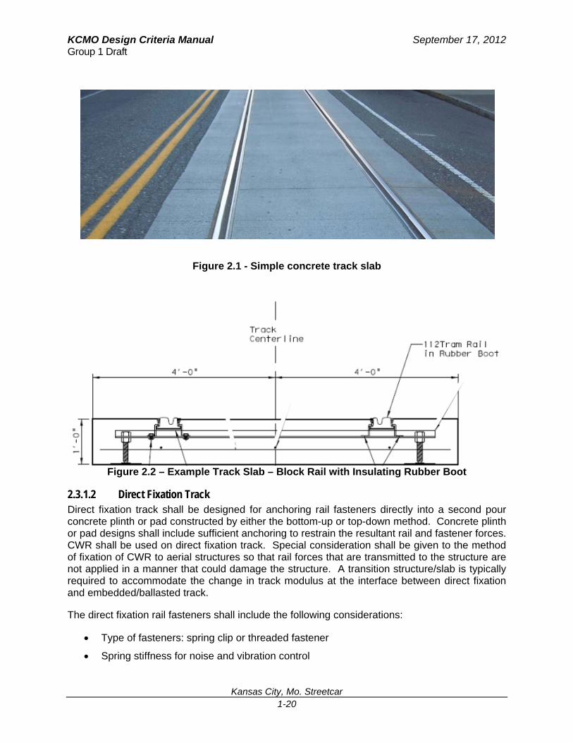
2.3.1.1 Embedded Track and Ballasted Track Embedded track shall be the standard for trackwork constructed where rail vehicles share the trackway with rubber-tired vehicles and/or pedestrians. An 8 foot wide by 10 - 14 inch deep concrete track slab (depending on rail section and geotechnical investigation) shall provide the foundation beneath this form of track construction, as shown in Figure 2.2. Reinforcing steel in the track slab shall be determined by the designer with respect to the geotechnical report and type of rail used. Ballasted track may be used for trackwork where rail vehicles are segregated from rubber-tired vehicles and pedestrians. Both ballasted and embedded track shall be constructed with continuous welded rail (CWR), unless specified otherwise.
KCMO Design Criteria Manual September 17, 2012 Group 1 Draft
Kansas City, Mo. Streetcar 1-20
Figure 2.1 - Simple concrete track slab
Figure 2.2 – Example Track Slab – Block Rail with Insulating Rubber Boot
2.3.1.2 Direct Fixation Track Direct fixation track shall be designed for anchoring rail fasteners directly into a second pour concrete plinth or pad constructed by either the bottom-up or top-down method. Concrete plinth or pad designs shall include sufficient anchoring to restrain the resultant rail and fastener forces. CWR shall be used on direct fixation track. Special consideration shall be given to the method of fixation of CWR to aerial structures so that rail forces that are transmitted to the structure are not applied in a manner that could damage the structure. A transition structure/slab is typically required to accommodate the change in track modulus at the interface between direct fixation and embedded/ballasted track.
The direct fixation rail fasteners shall include the following considerations:
Type of fasteners: spring clip or threaded fastener
Spring stiffness for noise and vibration control

KCMO Design Criteria Manual September 17, 2012 Group 1 Draft
Kansas City, Mo. Streetcar 1-21
Longitudinal restraint (fastener clip)
Rail cant
Type of anchor bolt assembly
Vertical and lateral adjustment capability
Electrical resistivity and insulation properties
The design of the concrete plinth or pad shall include the following considerations:
Plinth or pad dimensions to suit track alignment and to accommodate restraining rail and/or emergency guardrail where required
Interface connection of plinth or pad with elevated structure deck
Anchoring to restrain resultant rail forces
Elevated structure and rail interaction
Drainage of plinths or pads on elevated structure deck
2.3.1.3 Subgrade and Subballast The required thickness of either sub-ballast or subbase, if required, should be determined through a structural analysis of the track structure and geotechnical analysis of the engineering characteristics of the subgrade soils. In general the sub-ballast or subbase layer for primary track shall consist of a uniform layer of coarse aggregate that is placed over and follows the profile and cross section of the subgrade and is not less than 6 inches (150 mm) deep.
Sub-ballast is defined as a uniformly graded material that will provide a semi-impervious layer between the ballast and the subgrade. It facilitates drainage by shedding water off to the sides of the trackway, shielding the subgrade from moisture that percolates down through the ballast. Subbase material is used beneath pavement slabs such as those used in embedded track. The required gradation of the subballast layer shall be defined in the specifications.
2.3.1.4 Ballast No. 4 ballast gradation shall be used on all main ballasted tracks and No. 5 ballast gradation for ballasted yard and secondary track. Ballast gradation number shall be in conformance with the AREMA specifications. (If concrete ties are to be used in yard track, ballast should be No. 4.)

KCMO Design Criteria Manual September 17, 2012 Group 1 Draft
Kansas City, Mo. Streetcar 1-22
2.3.1.5 A minimum depth of 8 inches of ballast shall be used between the bottom of tie and the top of the sub-ballast (beneath the low running rail in super-elevated track and the inner running rail in tangent track). Ballast must be of sufficient depth to distribute pressure between the tie and subgrade. Ideal tie to ballast bearing pressures are 65 psi for timber ties and 85 psi for concrete ties. The ballast must sustain and transmit static and dynamic loads in three directions (transverse, vertical and longitudinal), distributing them uniformly over the subgrade. Slopes on ballasted sections, side slopes of earth shall generally be constructed at 2:1 or flatter. Side slopes of earth steeper than 2:1 may be used in special situations to avoid excessive earthwork or right-of-way costs; however, such slopes shall not be used without a soil engineer's determination of slope stability.
2.3.1.6 Track Drainage
2.3.1.6.1 Ballasted Track Drainage Ditches, grate drains, and/or underdrains shall be provided at the edges of the track to prevent water from ponding or covering any part of the track structure or contributing to subgrade instability. Minimum ditch grades will be 0.3%. In areas where the right-of-way does not allow use of the standard ditch section, underdrains may be used.
2.3.1.6.2 Embedded Track Drainage Track drains may be used in embedded track areas located in exclusive and non-exclusive alignments to properly drain the girder rail flangeways and the pavement surface between the rails when deemed necessary. Any use of grooved rail flangeway drain holes to be slotted through the flangeway groove must be approved by KCMO. Drains shall also be located at the low points of sag vertical curves unless a suitable alternative drainage method is considered and approved by KCMO. A track drain shall also be located at the track switches and on the downgrade end of all embedded track which adjoins ballasted track or direct fixation track so as to minimize fouling of the track ballast. If track drains are used, they shall be spaced, generally, every 500 to 600 feet on tangent level track to prevent the flangeways from overflowing and shall be electrically isolated from the running rails. Track drain frame and grate shall be designed to meet AASHTO HS-20 loading.
Track drains may be located adjacent to special trackwork to prevent water and dirt from entering such critical areas.
2.3.1.7 Transition Slabs Transition slabs shall be provided at all transitions between ballasted track and embedded/Direct Fixation track to accommodate the change in track modulus between the two systems.
2.3.2 Trackwork In addition to the criteria and standards defined in this section, all trackwork shall comply with the minimum standards of the following:
American Railway Engineering & Maintenance-of-Way Association (AREMA)
Association of American Railroads (AAR)
Federal Transit Administration (FTA)
American Public Transit Association (APTA)
KCMO Design Criteria Manual September 17, 2012 Group 1 Draft
Kansas City, Mo. Streetcar 1-23
Union Internationale de Chemins de Fer (UIC; Translation: International Union of Railways)
Verband Deutscher Verkehrsunternehmen (VDV; Translation: Union of German Transport Companies – for any elements of trackwork that are fabricated or constructed in accordance with European transit practices)
2.3.2.1 Track Gauge Track gauge is the distance between the inner sides of the head of rails measured 5/8 inch below the top of rails. For this project, track gauge shall be a standard gauge of 4 ft 8 ½ in (1435mm). To minimize excessive rail wear, wheel wear, and the potential for wheel squeal and derailments, the track gauge may need to be narrowed from the standard gauge of 4 ft 8 ½ in by ¼ inch in tight curves. After evaluating vehicle parameters the designer may choose to diverge from the standard gauge to apply the appropriate track gauge in these areas. Designer shall perform a wheel rail interface analysis for tight curves to determine the most appropriate gauge. Tee Rail (Figure 2.7) shall be installed with an inward cant of 1:40, except in portions of special trackwork where flat plates are customarily used. When block rail is used, no cant is required.
The track gauge and flangeway dimensions in curved embedded track using grooved rail and curved ballasted track using tee rail and restraining rail shall be established by using TCRP Report 155, “Track Design Handbook for Light Rail Transit”, Section 4.2.4, Gage Determination Analysis.
Full gauge narrowing/widening shall be accomplished on the tangent in approach to the point of curve and removed following the point of tangent in non-spiraled curves. In spiraled curves, gauge narrowing/widening shall be applied and removed over the length of the spirals. Gauge narrowing/widening shall be at a rate of not more than ¼ inch in a distance of 62 feet. If the spiral is too short for full gauge narrowing/widening to be accomplished without the rate exceeding ¼ inch in 62 feet, sufficient gauge narrowing/widening shall be placed in the approach tangents to meet the rate of ¼ inch in 62 feet.
2.3.2.2 Track Materials (Primary Track)
2.3.2.2.1 Running Rail All running rail within embedded track sections shall be either tee rail or grooved rail. All tangent sections of rail, embedded curve sections greater than 500-foot radius, and all yard tracks shall use either tee rail or grooved rail. Embedded rail sections with curves 500-foot radius or less (outside the yard track areas) shall use grooved rail or tee rail with associated guard rail. Additional specifications for the selection of running rail section and/or limits will be developed during the design process to suit site-specific conditions.
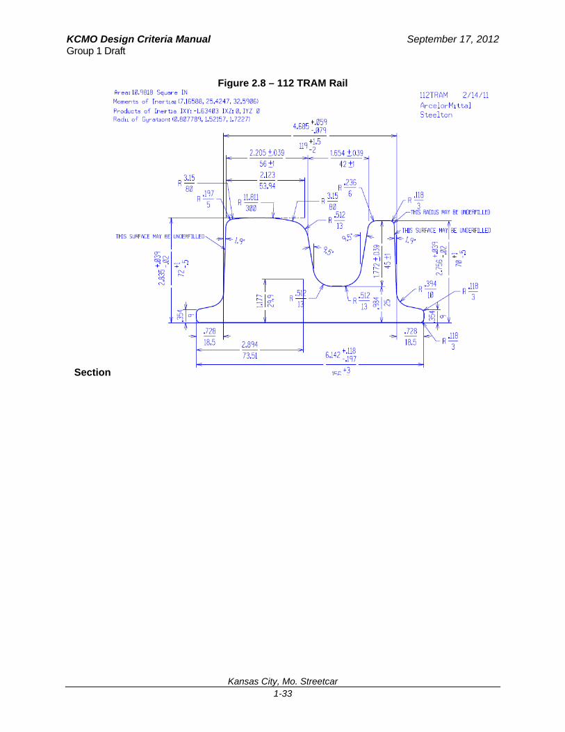
When using grooved rail, the designer shall consider using the following grooved rail section:
112 TRAM – Low profile (72mm) block rail (only grooved rail that meets Buy America)
The grooved rail section can be seen at the end of this Chapter, in Figures 2.8
KCMO Design Criteria Manual September 17, 2012 Group 1 Draft
Kansas City, Mo. Streetcar 1-24
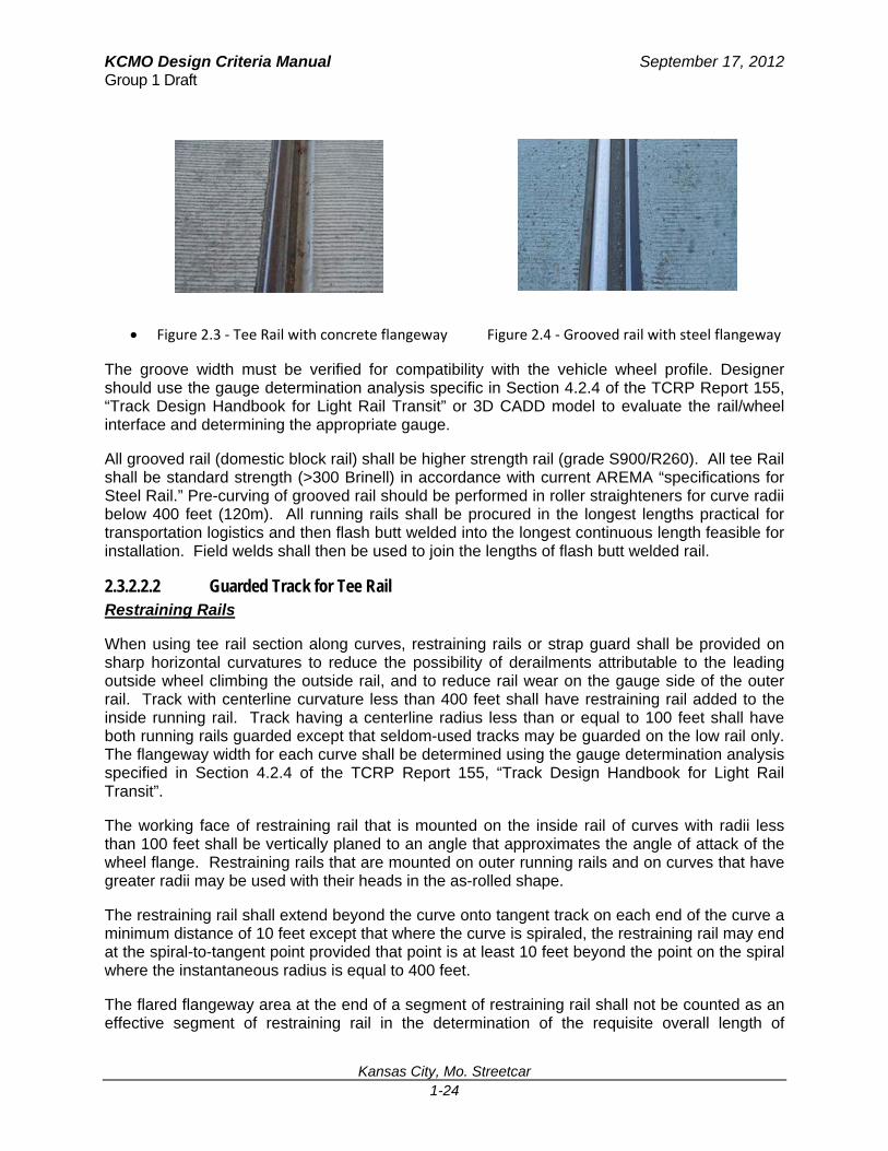
Figure 2.3 ‐ Tee Rail with concrete flangeway Figure 2.4 ‐ Grooved rail with steel flangeway
The groove width must be verified for compatibility with the vehicle wheel profile. Designer should use the gauge determination analysis specific in Section 4.2.4 of the TCRP Report 155, “Track Design Handbook for Light Rail Transit” or 3D CADD model to evaluate the rail/wheel interface and determining the appropriate gauge.
All grooved rail (domestic block rail) shall be higher strength rail (grade S900/R260). All tee Rail shall be standard strength (>300 Brinell) in accordance with current AREMA “specifications for Steel Rail.” Pre-curving of grooved rail should be performed in roller straighteners for curve radii below 400 feet (120m). All running rails shall be procured in the longest lengths practical for transportation logistics and then flash butt welded into the longest continuous length feasible for installation. Field welds shall then be used to join the lengths of flash butt welded rail.
2.3.2.2.2 Guarded Track for Tee Rail Restraining Rails
When using tee rail section along curves, restraining rails or strap guard shall be provided on sharp horizontal curvatures to reduce the possibility of derailments attributable to the leading outside wheel climbing the outside rail, and to reduce rail wear on the gauge side of the outer rail. Track with centerline curvature less than 400 feet shall have restraining rail added to the inside running rail. Track having a centerline radius less than or equal to 100 feet shall have both running rails guarded except that seldom-used tracks may be guarded on the low rail only. The flangeway width for each curve shall be determined using the gauge determination analysis specified in Section 4.2.4 of the TCRP Report 155, “Track Design Handbook for Light Rail Transit”.
The working face of restraining rail that is mounted on the inside rail of curves with radii less than 100 feet shall be vertically planed to an angle that approximates the angle of attack of the wheel flange. Restraining rails that are mounted on outer running rails and on curves that have greater radii may be used with their heads in the as-rolled shape.
The restraining rail shall extend beyond the curve onto tangent track on each end of the curve a minimum distance of 10 feet except that where the curve is spiraled, the restraining rail may end at the spiral-to-tangent point provided that point is at least 10 feet beyond the point on the spiral where the instantaneous radius is equal to 400 feet.
The flared flangeway area at the end of a segment of restraining rail shall not be counted as an effective segment of restraining rail in the determination of the requisite overall length of
KCMO Design Criteria Manual September 17, 2012 Group 1 Draft
Kansas City, Mo. Streetcar 1-25
restraining rail to be used. Flared portions of the restraining rail flangeway shall be at least as long in inches as the allowable track speed in mph with a minimum flare length of 12 inches.
2.3.2.2.3 Emergency Guard Rails Emergency guard rails shall be installed on track adjacent to all bridges, retained fills and their approaches that may cause extensive damage to a car and/or its passengers in the event of a derailment. Emergency guard rails shall begin 60 feet prior to the major structure and shall provide a 10 inch gap between the rail heads. Material for emergency guard rail shall be 80lb to 115lb second-hand rail.
On single track structures or for a single track located on retained fill, guardrail shall be installed adjoining both running rails. For double track, one guardrail is required for each track and it shall be located inside the running rail which is farthest from the edge of the structure.
2.3.2.2.4 Ballasted Track Special Trackwork The term “special trackwork” designates the trackwork units necessary where tracks converge, diverge or cross one another. Special trackwork typically includes, but is not limited to, turnouts, crossings and crossovers. All ballasted special trackwork design shall be based on AREMA standards except as modified to meet special conditions. All joints shall be welded.
All special trackwork shall be located on constant profile grades and in tangent sections of track only. There shall be no superelevation in any special trackwork units.
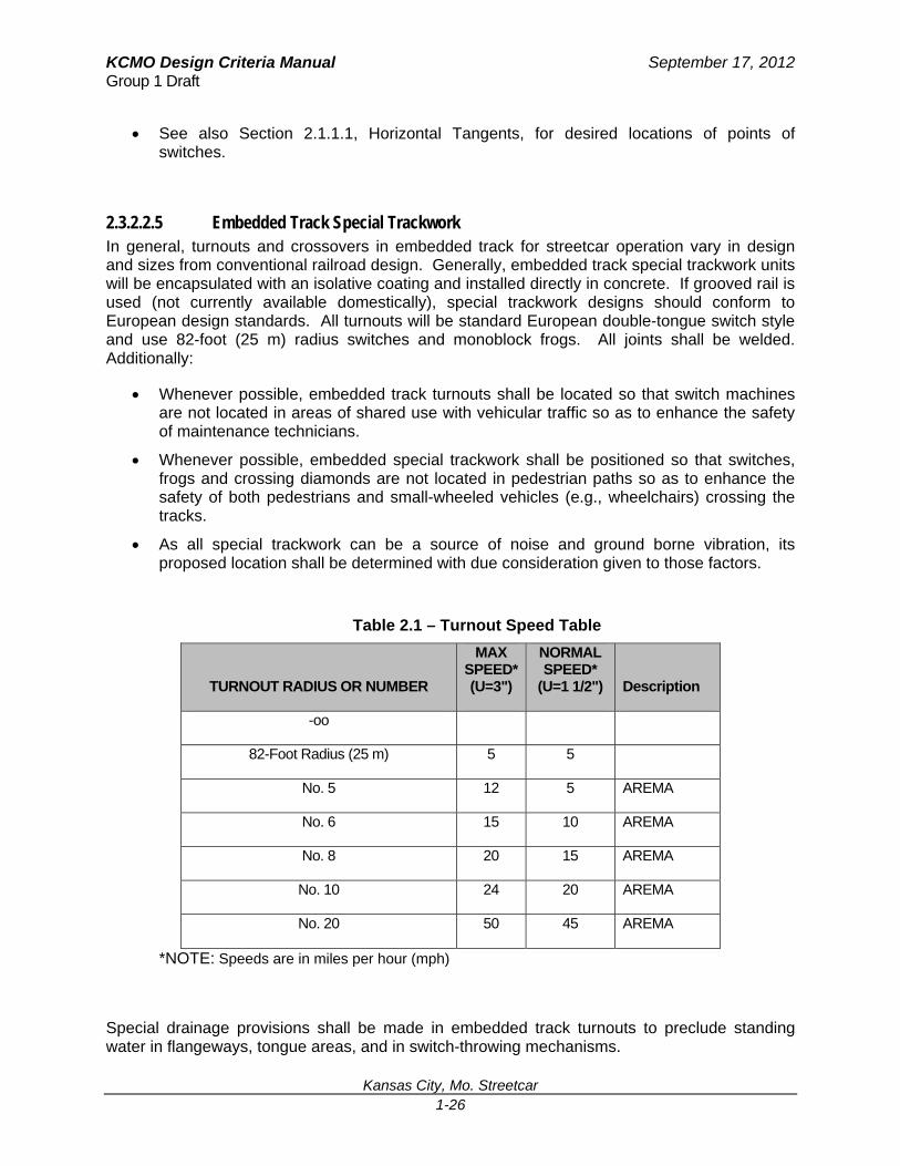
In general, turnouts shall be the flattest possible for a given location that is consistent with the desired track speed. As shown in Table 2.1 (in section 2.3.2.2.5), where turnouts occur in ballasted track, the following desirable minimum and absolute minimum criteria shall apply:
The yard tracks and main line tracks shall use #4 or 82-foot (25 m) turnouts.
Tee rail switches shall be of the uniform riser design per AREMA and shall employ the AREMA detail 5100 undercut "Samson" switch point detail modified to lower the running surface of the stock rail opposite the point. This modification is necessary to assure that wheels with worn flanges are intercepted and properly directed by the switch point. Flanges which have worn short can climb a 5100 detail used without the stock rail modification. All switch heel joints shall be of the floating heel block design except the yard tracks’ No. 5 switch heel joints.
Where a pair of crossovers is required, they should be set as two single crossovers if at all possible. If this is not possible, a double crossover may be used with the approval of KCMO.
Number 4 AREMA style turnouts will be used in the Maintenance and Storage Facility (MSF) yard. Turnouts can be installed in blasted track or installed on a concrete slab and direct fixation (DF). To avoid costly isolation measures, infill concrete is not required for turnouts installed with direct fixation on a slab. The rail will be exposed and isolated from the ground with the DF plates.
The rail section leading up to the MSF will be 80 to 115lb CWR tee rail. Number 5 ballast, a walkable ballast specifically designed for use in maintenance facilities, and No. 4 tee rail turnouts will be used for the MSF.
KCMO Design Criteria Manual September 17, 2012 Group 1 Draft
Kansas City, Mo. Streetcar 1-26
See also Section 2.1.1.1, Horizontal Tangents, for desired locations of points of switches.
2.3.2.2.5 Embedded Track Special Trackwork In general, turnouts and crossovers in embedded track for streetcar operation vary in design and sizes from conventional railroad design. Generally, embedded track special trackwork units will be encapsulated with an isolative coating and installed directly in concrete. If grooved rail is used (not currently available domestically), special trackwork designs should conform to European design standards. All turnouts will be standard European double-tongue switch style and use 82-foot (25 m) radius switches and monoblock frogs. All joints shall be welded. Additionally:
Whenever possible, embedded track turnouts shall be located so that switch machines are not located in areas of shared use with vehicular traffic so as to enhance the safety of maintenance technicians.
Whenever possible, embedded special trackwork shall be positioned so that switches, frogs and crossing diamonds are not located in pedestrian paths so as to enhance the safety of both pedestrians and small-wheeled vehicles (e.g., wheelchairs) crossing the tracks.
As all special trackwork can be a source of noise and ground borne vibration, its proposed location shall be determined with due consideration given to those factors.
Table 2.1 – Turnout Speed Table
TURNOUT RADIUS OR NUMBER
MAX SPEED* (U=3")
NORMAL SPEED*
(U=1 1/2") Description
-oo
82-Foot Radius (25 m) 5 5
No. 5 12 5 AREMA
No. 6 15 10 AREMA
No. 8 20 15 AREMA
No. 10 24 20 AREMA
No. 20 50 45 AREMA
*NOTE: Speeds are in miles per hour (mph)
Special drainage provisions shall be made in embedded track turnouts to preclude standing water in flangeways, tongue areas, and in switch-throwing mechanisms.
KCMO Design Criteria Manual September 17, 2012 Group 1 Draft
Kansas City, Mo. Streetcar 1-27
2.3.2.2.6 Frogs and Crossing Diamonds Turnout and crossing diamond frogs shall be designed to accommodate the narrow tread streetcar wheel and hence shall be configured for flange bearing use. On curved streetcar crossing diamonds, consideration shall be given to making the outer rail of the crossing diamond fully flange-bearing and the portions along the inner rail tread-bearing so as to take advantage of the steering effects of the different rolling radii of the flange tip versus the tread. All joints shall be welded.
2.3.2.2.7 Rail Fastenings, Rail Seats and Concrete Ties Running rail shall be fastened to its support in each type of track construction in a manner dependent upon the type of track construction and rail electrical insulation. All rail fastenings shall be in accordance with the current and applicable AREMA specifications.
Embedded rails shall be secured in place by the use of tie bars/clamp style rail clips assembly and/or anchor plates/clamp style rail clips assembly and elastomeric embedment material. Elastomeric material shall be pre-formed rubber boot. Rail embedment fixation and insulation details will be developed during the design process.
Concrete ties shall be used on ballasted track sections along the mainline and yard tracks. Concrete ties shall consist of pre-stressed monoblock concrete tie designed in accordance with AREMA, Manual for Railway Engineering, Chapter 10 – Concrete Ties and current ACI 318 Design Procedures. In addition to inserts for running rail elastic rail clips, concrete ties shall be designed with anchorage points for restraining rail and/or emergency guardrail as may be required. Rail seat areas shall be canted at 1:40. The elastic rail clip shall be a Pandrol Fastclip, Pandrol safelock clip, or approved equal.
2.3.2.2.8 Compromise Rail and Rail Joints Compromise rails shall be used to make the transition from grooved rail section to tee rail section or between rail profiles. Compromise rail shall be fabricated from high strength steel. All joints shall be welded.
Rail joints shall not be used except in those locations where it is absolutely necessary and only with the approval of KCMO.
All rail ends at rail joints shall be beveled and end-hardened. All joint bars shall be of the 36 inch, six-hole type conforming to the current AREMA specifications. High-strength track bolts shall be used in all rail joints except where expansion and contraction of rail must be allowed for structural and safety reasons.
2.3.2.2.9 Switch Machines Switch machines shall comply with the following as with Chapter 11, Streetcar Signaling and Route Control, of this manual. Additionally,
Power switch machines shall provide both point detection and manual operation override in the event of power or communication failure.
Hand throw / manual switch machines shall generally be of the spring/toggle type and will not normally require point detection or point locking.
KCMO Design Criteria Manual September 17, 2012 Group 1 Draft
Kansas City, Mo. Streetcar 1-28
Power switch machine earthbox for embedded turnout switches shall be designed to be installed between switch rails (in-board) and to be anchored on infill concrete inside the special trackwork insulated concrete bathtub.
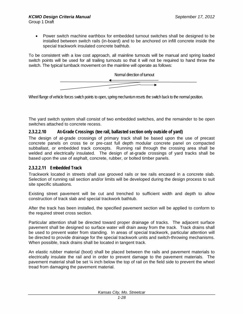
To be consistent with a low cost approach, all mainline turnouts will be manual and spring loaded switch points will be used for all trailing turnouts so that it will not be required to hand throw the switch. The typical turnback movement on the mainline will operate as follows:
Normal direction of turnout
Wheel flange of vehicle forces switch points to open, spring mechanism resets the switch back to the normal position.
The yard switch system shall consist of two embedded switches, and the remainder to be open switches attached to concrete recess.
2.3.2.2.10 At-Grade Crossings (tee rail, ballasted section only outside of yard) The design of at-grade crossings of primary track shall be based upon the use of precast concrete panels on cross tie or pre-cast full depth modular concrete panel on compacted subballast, or embedded track concepts. Running rail through the crossing area shall be welded and electrically insulated. The design of at-grade crossings of yard tracks shall be based upon the use of asphalt, concrete, rubber, or bolted timber panels.
2.3.2.2.11 Embedded Track Trackwork located in streets shall use grooved rails or tee rails encased in a concrete slab. Selection of running rail section and/or limits will be developed during the design process to suit site specific situations.
Existing street pavement will be cut and trenched to sufficient width and depth to allow construction of track slab and special trackwork bathtub.
After the track has been installed, the specified pavement section will be applied to conform to the required street cross section.
Particular attention shall be directed toward proper drainage of tracks. The adjacent surface pavement shall be designed so surface water will drain away from the track. Track drains shall be used to prevent water from standing. In areas of special trackwork, particular attention will be directed to provide drainage for the special trackwork units and switch-throwing mechanisms. When possible, track drains shall be located in tangent track.
An elastic rubber material (boot) shall be placed between the rails and pavement materials to electrically insulate the rail and in order to prevent damage to the pavement materials. The pavement material shall be set ¼ inch below the top of rail on the field side to prevent the wheel tread from damaging the pavement material.
KCMO Design Criteria Manual September 17, 2012 Group 1 Draft
Kansas City, Mo. Streetcar 1-29
During final design, alternative embedment methods for paved track shall be evaluated. If an alternate design for paved track proves to be advantageous, it may be substituted for the existing design with the approval of KCMO.
2.3.2.2.12 Insulated Joint Bars Insulated joint bars shall be provided wherever required for proper operation of the signaling system or where required to isolate one section of track from the traction power negative return circuit insulated joints are provided for signaling purposes. The signaling system shall include impedance bonds to provide a continuous path for traction negative power return current.
Insulated joint bars of epoxy bonded type shall be used in CWR wherever it is necessary to electrically isolate contiguous rail from each other in order to comply with track signaling or traction power criteria. Track bolts shall be equipped with self locking nuts wherever insulated joint bars are required in track constructed with jointed rail or where insulated joints are required in a running rail equipped with restraining rail. They shall be either polyurethane encapsulated or bolted insulated joints.
2.3.2.2.13 Bonded Joint Bars Except in those tracks designated as being constructed with jointed rail, bolted joints shall only be used between welded rail strings of different chemical composition or metallurgy. These joints shall be of the epoxy bonded type and shall be fastened with high strength bolts. Such joints shall be electrically bonded to provide a continuous path for traction power negative return current and signal circuits. They shall comply with following parameters:
Identical drilling pattern as standard joint bar
Compatible with the standard direct fixation rail fasteners
Comply with the general requirements of a rail joint as defined by the AREMA Manual for Railway Engineering
2.3.2.2.14 Rail Lubricators Automatic train-sensing rail lubricators shall be considered for any trackwork with horizontal curve of 500 feet radius or less. In some cases, rail lubricators have reduced significant noise caused by rail transit. Each curve will be evaluated on a case by case basis.
KCMO Design Criteria Manual September 17, 2012 Group 1 Draft
Kansas City, Mo. Streetcar 1-30
Figure 2.5 - Curve and Spiral Nomenclature
KCMO Design Criteria Manual September 17, 2012 Group 1 Draft
Kansas City, Mo. Streetcar 1-31
Figure 2.6 - Reverse Curve Super Elevation Transition

KCMO Design Criteria Manual September 17, 2012 Group 1 Draft
Kansas City, Mo. Streetcar 1-32
Figure 2.7 - Tee Rail Section
KCMO Design Criteria Manual September 17, 2012 Group 1 Draft
Kansas City, Mo. Streetcar 1-33
Figure 2.8 – 112 TRAM Rail
Section

KCMO Design Criteria Manual September 17, 2012 Group 1 Draft
Kansas City, Mo. Streetcar 1-34
THIS PAGE INTENTIONALLY LEFT BLANK

KCMO Design Criteria Manual September 17, 2012 Group 1 Draft
Kansas City, Mo. Streetcar 1-35
3.0 CIVIL WORK This chapter establishes the basic civil engineering criteria to be used in the preliminary design of the streetcar project. It includes criteria for the design of streetcar transit system surveys, drainage, roadways/paving, and determination of required rights-of-way.
3.1 Survey Control System All horizontal and vertical controls for this project shall be based on survey control points established under the direction of KCMO. Coordinates for project control points established for the system shall be based on the latest KCMO control network horizontally and vertically.
3.2 Drainage The goal in the design of rail transit system drainage is to protect the rail system track and facilities from stormwater runoff damage and to protect KCMO from liability for damage to property from resulting stormwater runoff, either passing through or caused by streetcar construction and permanent facilities, while maintaining consistency with the requirements of the Clean Water Act.
The design of drainage facilities shall be in accordance with the requirements of Kansas City Metropolitan Chapter of the American Public Works Association, Section 2150. The 100-year / 6-hour event shall be the design storm unless detention or retention ponding is required; then the 24-hr event or longer may be required.
Designs of drainage facilities belonging to other agencies which are relocated or modified because of streetcar construction and which do not cross or parallel streetcar system guideway or facilities shall conform to the design criteria and standards of the agency or jurisdiction involved.
Storm drain manholes should not be placed within the streetcar guideway unless absolutely necessary. When easements and right of way are involved manholes should be located in the right of way. Manholes should be located as close to changes in grade as feasible. As well, street catch basins should also follow these same criteria.
3.3 Right-Of-Way Streetcar rights-of-way shall be classified as either semi-exclusive or non-exclusive (mixed traffic). Semi-exclusive streetcar rights-of-way are those physically protected by curbs or barriers which prevent other vehicles from entering the right-of-way but which allow at-grade crossings. Non-exclusive right-of-way represents in-street operation in which track areas are also used by other traffic.
Right-of-way is the composite total requirement of all real property, interests and uses, both temporary and permanent, needed to construct, maintain, protect, and operate the streetcar. The intent is to acquire and maintain the minimum right-of-way required consistent with the requirements of the streetcar project.
The taking envelope is influenced by the existing topography, drainage, service roads, utilities, the nature of the streetcar structures selected, and disaster and/or fire fighting requirements.
KCMO Design Criteria Manual September 17, 2012 Group 1 Draft
Kansas City, Mo. Streetcar 1-36
Where property must be acquired to provide right-of-way for the streetcar project, such property acquisition shall be done in conformance with all appropriate city, state and federal regulations.
3.4 Roadways Roadway design in public rights-of-way shall be in conformance with the specifications and design guidelines of the local agency having jurisdiction. The structural cross section of the streetcar pavement shall be designed for a 20-year life to support the anticipated traffic use.
Road and parking surfaces shall be either Portland cement concrete pavement or Plant-Mix Bituminous Pavement. The criteria set forth in this section are applicable to the design or alterations to existing streets.
3.4.1 Applicable Standards Unless otherwise stated, roadway design shall be in accordance with the City of Kansas City Missouri (KCMO), Jackson County, and Missouri Department of Transportation (MoDOT) Design Standards except for design of new facilities or alterations to existing facilities to be owned or maintained by others. Those designs shall be in conformance with the current version of published standards and details of the local agency having jurisdiction.
The current versions of the following documents are incorporated into these design criteria by reference and should be adhered to wherever possible in the design of roads and parking and related traffic control.
Kansas City, Mo. Public Works Design Criteria And Construction Specifications
City of Kansas City, Mo. Public Works Standard Drawings
Kansas City Metropolitan Chapter of the American Public Works Association
Missouri Department of Transportation Plans Preparation Manual (PPM)
Missouri Department of Transportation Design Standards
ADA Standards for Accessible Design
Manual of Uniform Traffic Control Devices (MUTCD)
A Policy on Geometric Design of Highways and Streets (AASHTO)
Roadway Design Guide (AASHTO)
3.4.2 Roadway Geometrics Design of City of Kansas City, Mo. (KCMO) and Jackson County roadways shall be in accordance with A Policy on Geometric Design of Highways and Streets (latest version) of AASHTO, and as listed below in these criteria.
3.4.2.1 Traffic Lane Widths Traffic lane widths will be based on roadway classification. City streets shall be classified in accordance with KCMO roadway classification standards. In cases of significant constraint, a width reduction may be specified with the approval of KCMO.
KCMO Design Criteria Manual September 17, 2012 Group 1 Draft
Kansas City, Mo. Streetcar 1-37
3.4.2.2 Number of Traffic Lanes The number of traffic lanes and type of lanes (i.e., through, right, or left) shall be determined in consultation with KCMO and will be generally based on a traffic analysis which considers projected traffic volumes, streetcar vehicles intersection crossings, critical traffic movements, and geometric configurations.
3.4.2.3 Parking Lanes Parking lane locations shall be determined in consultation with KCMO based on traffic analysis, safety considerations and demand for on-street parking. Twenty-four hour parking prohibition shall be recommended at those locations (i.e., near intersections and at streetcar stops) where roadway width is not adequate to provide the necessary number of through lanes. Peak hour parking prohibition shall be recommended at those locations where traffic analysis shows that the capacity of the traveled way without the parking lane will not provide level of service required.
3.4.2.4 Vertical Clearance The minimum vertical clearance above the traffic lanes and shoulders on all roadways shall be 19 ft 0 in except where greater clearance is required by the agency having jurisdiction. The clearance shall apply over the entire vehicle roadway width including any contiguous auxiliary (turning) lanes and shoulders.
3.4.3 Curbs, Wheelchair Ramps and Curb Cuts Curb and/or gutter will be replaced only when impacted by improvements required by the streetcar project. Curbs will be installed/replaced per Jackson County/KCMO Standard Details, with the exception of the stop locations. Refer to Passenger Stops in Chapter 6, for information regarding curbs at stop platforms. Where the streetcar operates along a travel lane adjacent to on-street parking, a stop location is created by extending the sidewalk edge and curb line out to meet the travel lane (a bulb-out) which can result in the elimination of three or four parking spaces.
Wheelchair ramps with curb cuts shall be provided in accordance with the following:
Restore or replace any existing ramps impacted by construction. When intersection improvements are being implemented, all non-ADA-compliant pedestrian ramps at the intersection will be upgraded rather than only the affected quadrant per KCMO requirements.
Provide new ramps at intersections where sidewalk exists and the curb returns are modified as part of this project. It is not necessary to provide ramps and curb cuts where no sidewalk exists.
Provide ramps and curb cuts at intersections or mid-block locations where new curb and sidewalk will be constructed as part of this project.
The design and location of curb cuts and ramps shall be in accordance with the applicable provisions of KCMO, MoDOT and USDOT's Standards for Accessible Transportation Facilities to comply with the Americans with Disabilities Act (ADA).
KCMO Design Criteria Manual September 17, 2012 Group 1 Draft
Kansas City, Mo. Streetcar 1-38
At driveways, the curb and gutter shall be depressed across the vehicle opening as per KCMO standards.
3.4.4 Sidewalks Sidewalks shall comply with the standards of the applicable municipal or county jurisdiction. At a minimum, all sidewalks must have at least 4 feet in clear width. Cross slopes on sidewalks shall be a maximum of 2% per ADA guidelines. Existing sidewalks impacted by the project shall be repaired or replaced in kind, where practical. New sidewalks may be required at stops.
At stops, the minimum requirement for a sidewalk in front of the stop shelter is 3 feet from the edge of the detectable warning strip; with a 4 foot width being preferred. Access ramps for a stop with sidewalk behind the shelter will require extra sidewalk for a level landing area from the ramp(s) to allow for maneuverability between the ramp(s) and the sidewalk.
3.4.5 Driveways Driveway pavement types and minimum widths shall be as per KCMO standards. In general, all existing driveways impacted by the project shall be replaced in kind, where practical. Driveway closings required to facilitate streetcar operations or construction must be approved by KCMO.
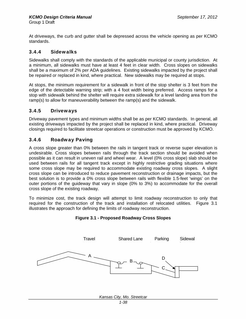
3.4.6 Roadway Paving A cross slope greater than 0% between the rails in tangent track or reverse super elevation is undesirable. Cross slopes between rails through the track section should be avoided when possible as it can result in uneven rail and wheel wear. A level (0% cross slope) slab should be used between rails for all tangent track except in highly restrictive grading situations where some cross slope may be required to accommodate existing roadway cross slopes. A slight cross slope can be introduced to reduce pavement reconstruction or drainage impacts, but the best solution is to provide a 0% cross slope between rails with flexible 1.5-feet ‘wings’ on the outer portions of the guideway that vary in slope (0% to 3%) to accommodate for the overall cross slope of the existing roadway.
To minimize cost, the track design will attempt to limit roadway reconstruction to only that required for the construction of the track and installation of relocated utilities. Figure 3.1 illustrates the approach for defining the limits of roadway reconstruction.
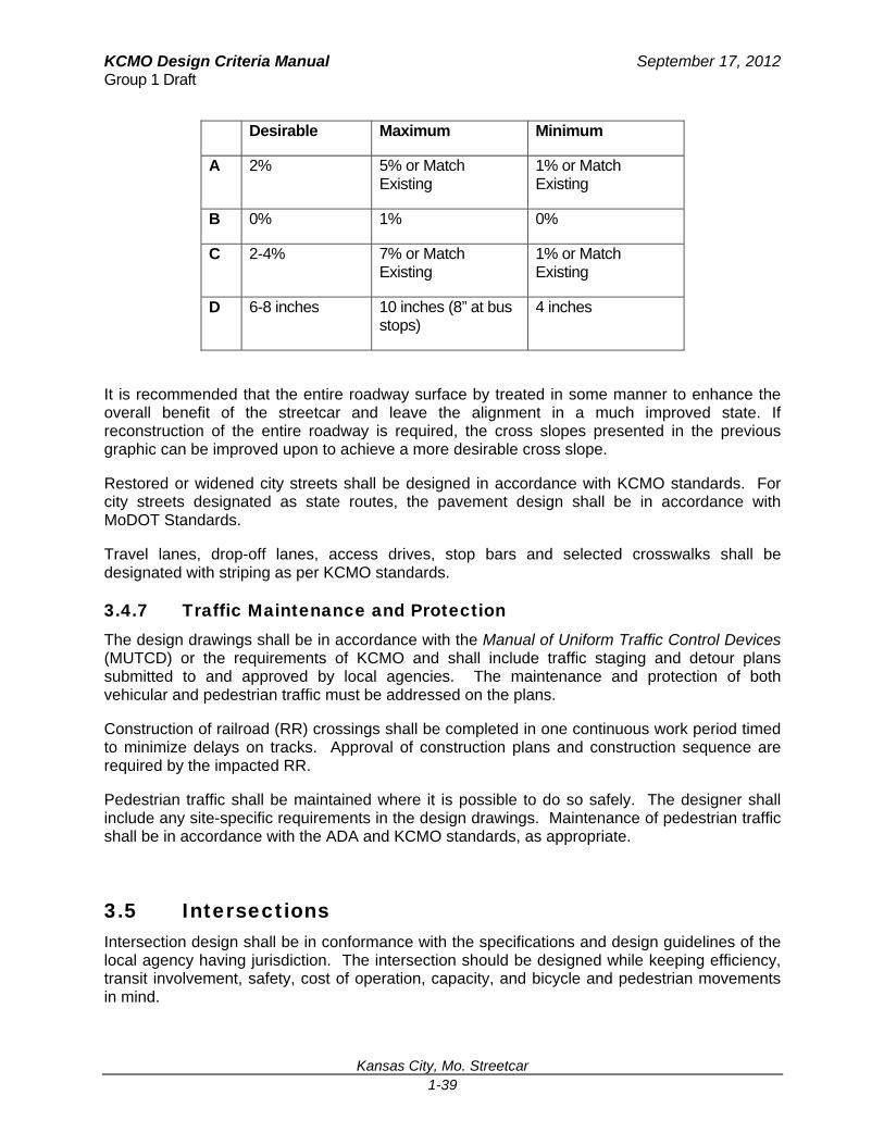
Figure 3.1 - Proposed Roadway Cross Slopes
Parking L
Shared Lane Travel L
A B
C
D
Sidewalk
KCMO Design Criteria Manual September 17, 2012 Group 1 Draft
Kansas City, Mo. Streetcar 1-39
Desirable Maximum Minimum
A 2% 5% or Match Existing
1% or Match Existing
B 0% 1% 0%
C 2-4% 7% or Match Existing
1% or Match Existing
D 6-8 inches 10 inches (8” at bus stops)
4 inches
It is recommended that the entire roadway surface by treated in some manner to enhance the overall benefit of the streetcar and leave the alignment in a much improved state. If reconstruction of the entire roadway is required, the cross slopes presented in the previous graphic can be improved upon to achieve a more desirable cross slope.
Restored or widened city streets shall be designed in accordance with KCMO standards. For city streets designated as state routes, the pavement design shall be in accordance with MoDOT Standards.
Travel lanes, drop-off lanes, access drives, stop bars and selected crosswalks shall be designated with striping as per KCMO standards.
3.4.7 Traffic Maintenance and Protection The design drawings shall be in accordance with the Manual of Uniform Traffic Control Devices (MUTCD) or the requirements of KCMO and shall include traffic staging and detour plans submitted to and approved by local agencies. The maintenance and protection of both vehicular and pedestrian traffic must be addressed on the plans.
Construction of railroad (RR) crossings shall be completed in one continuous work period timed to minimize delays on tracks. Approval of construction plans and construction sequence are required by the impacted RR.
Pedestrian traffic shall be maintained where it is possible to do so safely. The designer shall include any site-specific requirements in the design drawings. Maintenance of pedestrian traffic shall be in accordance with the ADA and KCMO standards, as appropriate.
3.5 Intersections Intersection design shall be in conformance with the specifications and design guidelines of the local agency having jurisdiction. The intersection should be designed while keeping efficiency, transit involvement, safety, cost of operation, capacity, and bicycle and pedestrian movements in mind.
KCMO Design Criteria Manual September 17, 2012 Group 1 Draft
Kansas City, Mo. Streetcar 1-40
In general, existing intersections significantly impacted by the project will be reconstructed to applicable standard. Intersection closings required to facilitate streetcar operations or construction must be approved by KCMO.
3.6 Pedestrians and Bicyclists Pedestrian and bicycle facilities should be considered as part of the overall design of the transit network and if impacted the reconstruction shall comply with the standards of the applicable municipal or county jurisdiction.
Impacts to Pedestrian facilities include sidewalks, crosswalks, traffic control features, curb cuts, bus stops, etc. As well, impacts to bicycle facilities include paved shoulders, wide outside traffic lanes, bicycle safe drainage grates, manholes, striping, and smooth riding surfaces.

KCMO Design Criteria Manual September 17, 2012 Group 1 Draft
Kansas City, Mo. Streetcar 1-41
THIS PAGE INTENTIONALLY LEFT BLANK
KCMO Design Criteria Manual September 17, 2012 Group 1 Draft
Kansas City, Mo. Streetcar 1-42
6.0 STATION/STOP DESIGN
6.1 Streetcar Stop Design The layout and design of a streetcar stop will be dependent upon a number of factors including:
location of the stop in the roadway (curb-side or median)
location of the stop with respect to an intersection (near or far-side)
dimensions and configuration of the streetcar/bus vehicle, including presence of doors and ADA boarding locations
availability of space (including sidewalk) behind the street curbs and with-in the right of way
type of shelter (if desired/required) to be provided at a stop
presence or absence of on-street parking at the site of the stop
Americans with Disabilities Act (ADA) Standards for Accessible Design
codes, regulations, and standards, including but not limited to:
o Americans with Disability Act (ADA) Title II Regulations (Title II), American with
Disabilities Act Title III Regulations (Title III), and ADA Accessibility Guidelines for
Buildings and Facilities (ADAAG);
o Code of Federal Regulations (CFR), 49 CFR Part 38 – Accessibility Specifications for
Transportation Vehicles;
o Uniform Building Code;
o National Fire Protection Association (NFPA) Standards (NFPA 130, NFPA 72, NFPA 70,
and NFPA 101); and
o Federal/local/state codes and regulations.
6.2 Dimensions of Stop For the streetcar alternatives, the length of the stop can only be assumed in early project phases because it is dependent upon the location of the doors on the streetcar vehicle. The minimum length of the platform should match the low-floor boarding area of the streetcar between doors. Since that length can vary among streetcar manufacturers, KCMO and KCATA have the luxury of establishing criteria for platform lengths that accommodate parking and access to the stop. Most curb extension side stops are bulb outs occupying existing parking spaces. Theses stops require approximately 60-70 feet to provide a minimum of 40 feet of tangent (boarding area) and 20-30 feet to transition the “bulb out” curb extension back to the existing curb line. This results in the loss of approximately three parallel parking spaces. It is recommended that a minimum of 60-70 feet be allotted for streetcar side stops, which allows ample space for a boarding platform, access ramps, and a basic level of amenities at the stop.
The width of the streetcar stop is dependent on a number of factors:
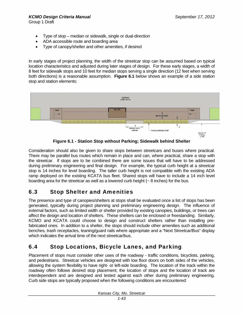
KCMO Design Criteria Manual September 17, 2012 Group 1 Draft
Kansas City, Mo. Streetcar 1-43
Type of stop – median or sidewalk, single or dual-direction ADA accessible route and boarding area Type of canopy/shelter and other amenities, if desired
In early stages of project planning, the width of the streetcar stop can be assumed based on typical location characteristics and adjusted during later stages of design. For these early stages, a width of 8 feet for sidewalk stops and 10 feet for median stops serving a single direction (12 feet when serving both directions) is a reasonable assumption. Figure 6.1 below shows an example of a side station stop and station elements:
Figure 6.1 - Station Stop without Parking; Sidewalk behind Shelter
Consideration should also be given to share stops between streetcars and buses where practical. There may be parallel bus routes which remain in place and can, where practical, share a stop with the streetcar. If stops are to be combined there are some issues that will have to be addressed during preliminary engineering and final design. For example, the typical curb height at a streetcar stop is 14 inches for level boarding. The taller curb height is not compatible with the existing ADA ramp deployed on the existing KCATA bus fleet. Shared stops will have to include a 14 inch level boarding area for the streetcar as well as a lowered curb height (~ 8 inches) for the bus.
6.3 Stop Shelter and Amenities The presence and type of canopies/shelters at stops shall be evaluated once a list of stops has been generated, typically during project planning and preliminary engineering design. The influence of external factors, such as limited width or shelter provided by existing canopies, buildings, or trees can affect the design and location of shelters. These shelters can be enclosed or freestanding. Similarly, KCMO and KCATA could choose to design and construct shelters rather than installing pre-fabricated ones. In addition to a shelter, the stops should include other amenities such as additional benches, trash receptacles, leaning/guard rails where appropriate and a “Next Streetcar/Bus” display which indicates the arrival time of the next streetcar/bus.
6.4 Stop Locations, Bicycle Lanes, and Parking Placement of stops must consider other uses of the roadway - traffic conditions, bicyclists, parking, and pedestrians. Streetcar vehicles are designed with low floor doors on both sides of the vehicles, allowing the system flexibility to have right- or left-side boarding. The location of the track within the roadway often follows desired stop placement; the location of stops and the location of track are interdependent and are designed and tested against each other during preliminary engineering. Curb side stops are typically proposed when the following conditions are encountered:
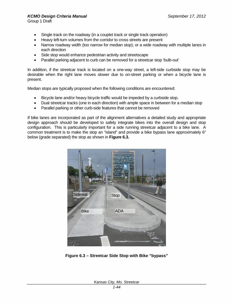
KCMO Design Criteria Manual September 17, 2012 Group 1 Draft
Kansas City, Mo. Streetcar 1-44
Single track on the roadway (in a couplet track or single track operation) Heavy left-turn volumes from the corridor to cross streets are present Narrow roadway width (too narrow for median stop); or a wide roadway with multiple lanes in
each direction Side stop would enhance pedestrian activity and streetscape Parallel parking adjacent to curb can be removed for a streetcar stop ‘bulb-out’
In addition, if the streetcar track is located on a one-way street, a left-side curbside stop may be desirable when the right lane moves slower due to on-street parking or when a bicycle lane is present.
Median stops are typically proposed when the following conditions are encountered:
Bicycle lane and/or heavy bicycle traffic would be impeded by a curbside stop. Dual streetcar tracks (one in each direction) with ample space in between for a median stop Parallel parking or other curb-side features that cannot be removed
If bike lanes are incorporated as part of the alignment alternatives a detailed study and appropriate design approach should be developed to safely integrate bikes into the overall design and stop configuration. This is particularly important for a side running streetcar adjacent to a bike lane. A common treatment is to make the stop an “island” and provide a bike bypass lane approximately 6” below (grade separated) the stop as shown in Figure 6.3.
Figure 6.3 – Streetcar Side Stop with Bike “bypass”
ADA Bike
StopSidewal

KCMO Design Criteria Manual September 17, 2012 Group 1 Draft
Kansas City, Mo. Streetcar 1-45
Careful planning, design and coordination with the bike and pedestrian community throughout the project development will result in a more comprehensive design and safer operating environment for all users of the public’s right of way.
6.5 Public Art Successful public works and transportation projects with integrated public art are important to the community of Kansas City, Missouri. The goal for the public art program is to enrich the transit experience, promote a sense of scale, and reinforce the connections of the diverse communities along the route. Artwork enhancing streetcar experience as unique, aesthetically and culturally relevant to this community is of high interest. The KCMO Modern Streetcar public art program will be coordinated and managed by the Public Arts Program Coordinator, with support from the Streetcar Project Management team. Specific duties of the Public Arts Program Coordinator include:
Implementation of the Modern Streetcar art program according to program direction from KCMO and its Program Management team;
Retention, administration and management of artists for both levels of art opportunities; Assistance in efforts to gather input and support for the art projects from the community
and stakeholders; and Coordination between design and construction contracts for the art projects during the
engineering and construction phases of the Kansas City, Missouri Modern Streetcar project.
The community will be involved during the public art program through representation on the Project Panel for streetcar public artist selection and design review, along with any citizen advisory committees established through the course of a streetcar project.

KCMO Design Criteria Manual September 17, 2012 Group 1 Draft
Kansas City, Mo. Streetcar 1-1
THIS PAGE INTENTIONALLY LEFT BLANK