strength of materials lec 38 · 2019-07-15 · strength of materials prof. s. k. bhattacharyya...
TRANSCRIPT

Strength of Materials
Prof. S. K. Bhattacharyya
Department of Civil Engineering
Indian Institute of Technology, Kharagpur
Lecture – 38
Stability of Columns - II
Welcome to the second lesson of the ninth module which is on stability of columns part II. In fact,
in the last lesson we have introduced the concept of the buckling in a member, a vertical member
which is subjected to complexity force which we have termed as column and also we have looked
into the stability aspects of different types of column members and thereby we have introduced
the derivations which was proposed by Leonhard Euler which we normally call as Euler’s buckling
load formula.
Now in this particular lesson we are going to look into the aspects where the Euler’s load can be
applied or in other words, what are the limitations of Euler critical buckling load in applying in the
column members and subsequently also we look into what are the other formulas that can be used
for evaluating the critical load in a column member.
(Refer Slide Time: 01: 40)

It is expected that once this particular lesson is completed, one should be in a position to understand
the limitations of Euler’s critical buckling load formula and also we look into the concept of
intermediate columns and evaluation of buckling load using Rankine’s formula. Also, one should
be in a position to evaluate critical buckling load in different types of column members. When we
talk of different types we mean that the column members are having different support conditions.
As we have seen in the previous lesson the column members can be having the hinged ends or it
can have fixed ends and also fixed and hinged or combinations of these and then how do you
calculate the critical buckling load in such column members having these different types of
supports.
(Refer Slide Time: 02:35 - 03:27)
The scope of this particular lesson therefore includes the recaπtulation of previous lesson. We will
look into some aspects of the lesson which we have discussed in the previous class wherein we
have given the concept of the buckling and the stability and we have discussed the Euler’s critical
buckling formula; we will look into some more aspects of that.
We will look into the limitations of Euler’s critical buckling load formula and also this particular
lesson includes this Rankine’s critical buckling load for intermediate columns. In fact, we will
look in to what we really mean by intermediate column and how do we evaluate the critical

buckling load using this Rankine’s formula. And also we will look into some example for the
evaluation of buckling load in columns of different support conditions.
(Refer Slide Time: 3:33)
Well, before we proceed, let us look into the answers to the questions which we posed last time.
The first question given was what is meant by critical buckling load of columns? Now let us discuss
this with respect to the buckling model which I discussed last time in the previous lesson.
(Refer Slide Time: 03:50 - 07:17)

If u remember, the actual column supposing if we consider an idealized column which is hinged
at both ends and which is perfectly straight subjected to axial load these we can model as having
two digit bars AB and BC and connected with a rotational spring at point B, the spring stiffness of
this rotational spring being beta; and this particular system where AB and BC are perfectly
concentric the axial load P is acting in this member which is also concentric.
Now if we give lateral load to these or a little disturbance to this kind of a system then it is expected
that the bars will move thereby an angle ϴ will be made by these bars and the rotational spring
which is provided at B having the stiffness beta will produce a restoring movement the magnitude
of which will be equals to the total rotational angle that these two bars will be undergoing which
is twice 2ϴ this spring is undergoing so beta times 2ϴ is the restoring movement. If I call that as
MR this is equals to beta time 2ϴ.
Now if we remove this disturbing load as we have given a disturbance and brought the columns
bought this systems in this particular form, if we remove the disturbance it is expected that the bars
will come back to its original position because this restoring movement given by the rotational
spring will overpower the effect of this axial load and thereby this kind of a system we call as a
stable system where the restoring movement is larger than the axial load P which is acting on this
particular member.
(Refer Slide Time: 5:53)

Now as you can see that when the rotational spring is giving a restoring movement the axial load
P is giving opposing action that means it is trying increase the movement of the point B and thereby
it tries to create destabilization in the system. now supposing if we keep on increasing this load to
such a to such an extent that the axial load exceeds the restoring movement capacity that means
the movement produced by this axial load through this movement if that exceeds the rotational the
restoring movement capacity then the system will no longer be in the equilibrium position and it
will fail and if we remove the external disturbance the restoring movement will not be or the spring
will not be in a position to restore back the normal position and thereby the system becomes
unstable.
Now between these two positions the stable and unstable position there is unique value of the load
P which we call as the critical load. This is what is stated over here that the transition between the
stable and unstable condition that occurs at a special value of the axial force which we term as
critical load. In fact critical load is that load beyond which if we add a little load to the system the
system will come unstable or it will fail by excessive deformation or unrestraint deformation which
we call as buckling. So the member will no longer be in a stable state but it will become unstable
and it will fail. That is the load; there is the limiting value of the load; beyond which the member
fails with little addition of the load we call that limiting load as the critical load. (Refer Slide Time:
07: 53)
And as we have seen that last time we had derived for this particular buckling model that what will
be the value of the critical load, now as we have seen that the restoring movement is equals to beta
times 2ϴ the total rotation that it undergoes and if we take the equilibrium of the forces for this
particular free body as we have seen that the horizontal force is equal to zero now if we take the
movement of all the forces which is respect to B we get,
. 2
20
22
. 0
4
Now this value of P becomes critical when this matches the restoring moment M. Now, as soon as
when this particular state if we add additional load over here delta P then the system is going to
collapse and that is the reason this load is called as the critical load P cr.
(Refer Slide Time: 9:07)
Now let us look into the other questions. The second question given was how will you evaluate
the critical compressive stress in a column member? Now that we have discussed about the critical

load that a column member when subjected to axial load when it reaches to criticality then what is
the corresponding critical compressive load?
Now what we are interested in as we have seen earlier that if we like to evaluate the stress
corresponding to that critical load then what is the; which we term generally as critical compressive
load how to compute that? And the third question what is given is what is meant by slenderness
ratio? In fact I like to answer these two questions together, both the second and third questions
simultaneously.
(Refer Slide Time: 9:50)
Let us look into the formula which we have derived or which was given by Leonard Euler that the
Pcr is equal to,
Where, r = radius of gyration and Le/r is the slenderness ratio.
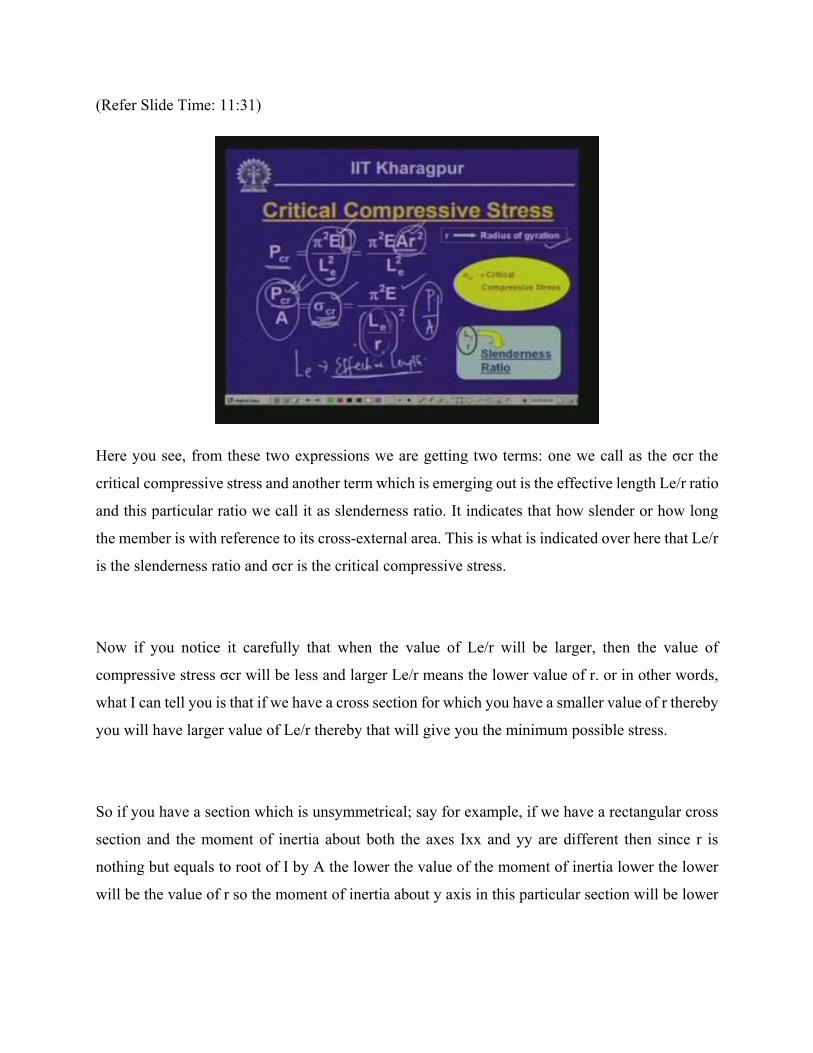
(Refer Slide Time: 11:31)
Here you see, from these two expressions we are getting two terms: one we call as the σcr the
critical compressive stress and another term which is emerging out is the effective length Le/r ratio
and this particular ratio we call it as slenderness ratio. It indicates that how slender or how long
the member is with reference to its cross-external area. This is what is indicated over here that Le/r
is the slenderness ratio and σcr is the critical compressive stress.
Now if you notice it carefully that when the value of Le/r will be larger, then the value of
compressive stress σcr will be less and larger Le/r means the lower value of r. or in other words,
what I can tell you is that if we have a cross section for which you have a smaller value of r thereby
you will have larger value of Le/r thereby that will give you the minimum possible stress.
So if you have a section which is unsymmetrical; say for example, if we have a rectangular cross
section and the moment of inertia about both the axes Ixx and yy are different then since r is
nothing but equals to root of I by A the lower the value of the moment of inertia lower the lower
will be the value of r so the moment of inertia about y axis in this particular section will be lower

so r y is going to give us the lower value out of the two r values. Therefore, minimum of this r will
give us the value of larger Le/r and thereby will have lower stress that is what is the critical stress.
So if you have a cross section wherein you have different values of the moment of inertia about
two rectangular access system x and y thereby we must deal with the minimum value of the radius
of direction so that you get critical value of the slenderness ratio which is Le/r which is larger. And
as we are looking in to it here the larger the value of the slenderness ratio smaller will be the stress
thereby, if you consider that particular stress with the cross-sectional area that will give you the
load getting capacity of the member. Hence you will have to always look for that what is the
minimum possible stress that will be required otherwise the member will fail by buckling if we go
beyond that particular load. This is what is important when we talk about the stresses the
slenderness ratio Le/r and the critical compressive stress σcr.
(Refer Slide Time: 14:16)
Well, having looked in to these questions let us once again look back to the values of the critical
load that we had evaluated or which was derived by Leonard Euler for different column support
conditions.
(Refer Slide Time: 14:40)

Now, first one which was an idealized column member we had considered wherein the hinge of
the column members were hinged and that is what we have put as hinged and hinged and as we
had seen the Euler’s critical load corresponding to this kind of column having length L is equal to
π2 EI/L2. When the support condition changes say the lower becomes fixed and the top becomes
free which is that of a cantilever member this kind of member we call as cantilever member as we
have seen in beams. now here the condition is a fixed free condition and the Euler’s critical
buckling load which we get corresponding to this is, π2 EI/4L2
In hinged-hinged condition, since, Pcr = π2 EI/L2, Le = L, here we have the coefficient of L = 1, or,
K = 1
In fixed-free condition, since, Pcr = π2 EI/4L2, Le = 2L, coefficient K = 2
In fixed-free condition, since, Pcr = 2π2 EI/L2, Le = L/√2= 0.707L, coefficient K = 0.7
In fixed-free condition, since, Pcr = 4π2 EI/4L2, Le = 0.5L, coefficient K = 0.5
Thus we see that we get different values of the K or the coefficient of the effective length based
on which we can compute the value of the critical compressive load for each of such column
members. And as we have seen now that once we can evaluate the critical compressive load
correspondingly we can evaluate the value of the critical compressive stress as well.
(Refer Slide Time: 18:13)

Having looked into this let us look into the variation of this stresses and the assumptions with
which this Euler’s formula were derived.
(Refer Slide Time: 18:39 - 19:16)
Now you see, when we have derived or when the formula was proposed by Leonard Euler it was
assumed that the column member is perfectly straight that means we had considered an idealized
situations that the column member is perfectly straight and subjected to a compressive load which
is truly axial; that means it is passing through the centroid line of the cross external member of the
column member. So, the column is initially straight, the load is truly axial and the material is

homogenous and isotropic and behaves elastically up to the critical load. So up to the limit of the
critical load we presume that the material behaves in an elastic manner and thereby the Hook’s
law is applicable. Therefore, beyond critical load there might be inelastic deformation or beyond
buckling when the buckling occurs the failure subsequently could be in an elastic manner which
is of course not in the scope of this particular lesson.
(Refer Slide Time: 19:47)
Now if you look in to the Euler’s critical buckling load formula you will observe that we had the
Pcr = π2EI/Le2. Now we are talking about a critical load that means how much load a member can
carry which must be related to the strength of the column. But unfortunately we do not have any
parameter in this particular expression which signifies the strength of the member; instead what
we have is the elastic modulus e only which is the material characteristics present in this particular
expression. This is what is written over here; you see that Euler’s critical load formula is used in
connection with the strength of the column but the formula does not contain any variable related
to the strength of the material and this is what is very important.
(Refer Slide Time: 20:45)

Hence, the only property that is invoked in this particular expression is e which is the elastic
modulus of this material that we are using.
(Refer Slide Time: 20 53)
Well, now with this background if we look into the variation of the critical stress with the
slenderness ratio Le/r we will find, as we have discussed in this particular section.
As I was telling you that if this value of slenderness ratio increases then the value of the σcr
decreases. If the Le/r value becomes lower and lower that means the stress level will be higher and

higher. Now what does that imply? That means if you have a very small Le/r or very small value
of the slenderness ratio you will have very high value of the stress. But what does that physically
mean?
Supposing if you have a stress which is much higher than the yield stress of the material then what
is going to happen; the material is going to fail as soon as it crosses the yield stress. So the stress
higher than yield stress makes no sense. So what happens is if we are talking about a column where
the slenderness ratio is very low or as we have seen that in case of short column the critical stress
thereby is the yield stress the yield stress is the critical value because once the member reaches to
the yield stress the material is going to yield and as we have noticed earlier as we have discussed
earlier that for a short column when it is subjected to axial load or even if the load is eccentric
thereby it is going to give you the axial load and the bending and in terms of the combined stresses
if you compute the normal and the bending stresses in the member, as soon as the stress level goes
beyond the yield stress the member is going to fail by crossing that means the material will yield
and the question of buckling will not arise in that particular situation.
2 10210
97
Hence, this Euler’s critical load formula has a limitation that beyond a certain value of Le/r we
cannot use this Euler’s critical buckling load formula. Now, if we consider the material as steel
material which we know that the proportional limit stress the σ PL is equal to 210 MPa and the
yield stress say we consider as 250 MPa then if we consider that the proportional limiting stress
which is equal to 210 MPa then we get a value of slenderness ratio Le/r as equals to 97. This
indicates that if we use the slenderness value less than 97 then the stress level is going to go beyond
the proportional limit.

(Refer Slide Time: 24:01)
As we have noticed, if the stress level goes beyond the value of σ y then the material is going to
fail by crossing which is the criteria for a short column. Hence, there is a limiting value for the
slenderness beyond which the Euler’s critical load formula is applicable; otherwise it is not
applicable for such type of members. So, in this particular curve as you can see where σcr is plotted
against the slenderness ratio Le/r, there is a limiting value of the slenderness and this curve (Refer
Slide Time: 24:41) or the Euler’s curve is valid when Le/r is greater than this limiting value. When
Le/r is higher, let us call this Le/r as the limiting value. this is the Le/r which we have computed
for steel and let us call this Le/r as the limiting value.
Now, when actual Le/r in the member is greater than the limiting value of the slenderness ratio
then we can use the Euler’s critical load formula. But if it is less than this value; if actual Le/r is
less than the limiting Le/r value then we cannot use the Euler’s column buckling formula. So what
happens is you see that we are getting clearly two areas: one is that beyond the limiting Le/r or the
slenderness ratio or higher the value of limiting value we can go for the Euler’s critical buckling
load formula based on which we can compute the critical load in the member and the other aspect
is that as we can see that when the stress goes beyond the yield stress the material is going to fail
by yielding.

So, for the short columns when σy is the critical stress we can evaluate what will be the load
carrying capacity. So, between these two cases that you have a short column where the member is
going to fail by yielding and a long column formula where beyond a limiting value of the
slenderness ratio we are using Euler’s column buckling formula now in between these two there
could be some members which may failed in the combination of buckling and yielding and those
members which are in between this short column and long column we call them as intermediate
columns.
As we have noticed that intermediate columns will have L/r less than the limiting value of L/r or
Le/r and thereby will not be in a position to apply Euler’s critical buckling load formula for
evaluating the critical compressive load for such members. For such intermediate members we use
different formulas. In fact there is a formula which was proposed by Rankine we call that as
Rankine’s formula for evaluating the critical load in intermediate columns; so, for both short
columns and intermediate columns in fact the Euler’s column Euler’s formula will not be
applicable and it will not give you the appropriate results.
(Refer Slide Time: 27:16)
Now let us look into this Rankine’s formula which was proposed by Rankine which we commonly
call as Rankine Gordon formula.
(Refer Slide Time: 27:30)

These are applicable for the intermediate columns and Rankine suggested that an empirical
relationship for evaluating buckling load in this form which reads as 1/Pr is equal to 1/Ps plus 1/Pe
where Pr is termed as the Rankine’s buckling load, Ps is the direct compressive load which is equals
to the yield stress multiplied by the area and Pe is the Euler’s critical buckling load formula or
buckling load. So we have three terms Pr, Ps and Pe where P r is the critical buckling load that is
given by Rankine and that is what we are interested to evaluate and that is being evaluated in terms
of Ps and Pe; Ps is the load which is evaluated from the direct compressive stress and that is for the
short column and as you know for the short column the critical compressive stress is nothing but
the yield stress σy.
So this particular expression that
1 1 1
1 / .
1 . /

.
1
(Refer Slide Time: 29:42)
Now here the σy/π2E which is dependent on that material the yield stress of the material and the
modulus of elasticity of the material is commonly termed as Rankine’s constant. And again as you
can see that the critical load for the member will dependent on this Le/r the slenderness ratio and
the critical stress or the yield stress of the material. This is the expression which was proposed by
Rankine for evaluating the critical buckling load for the intermediate column members.
(Refer Slide Time: 30:16)

Now as we have seen clearly we have three distinct areas: one we have called as short column,
another we have called as long column and now we have defined another column range which is
between short column and the long column. For the other long column members we can use Euler’s
critical buckling load formula for evaluating the critical compressive load when the actual
slenderness ratio Le/r ratio of the member exceeds the limiting slenderness value. as we have just
now seen, for any material we can compute Le/r limiting for a particular material and when the
column member is made up of that material, if we know the actual slenderness and when that
actual slenderness exceeds the limiting value then we can use the Euler’s column formula for
evaluating the critical load; or if the actual Le/r is much less than the limiting Le/r value wherein
the failure will be governed mainly by the yielding of the material; wherein we take the critical
compressive stress as the yield stress of the material that multiplied by the cross-sectional area will
give the critical load as that of a short column and in between these two where the members could
fail in the combination of the crossing or yielding and the buckling those types of columns we call
as intermediate column and we can evaluate the critical buckling load of those columns using
Rankine’s formula.
(Refer Slide Time: 31:56)
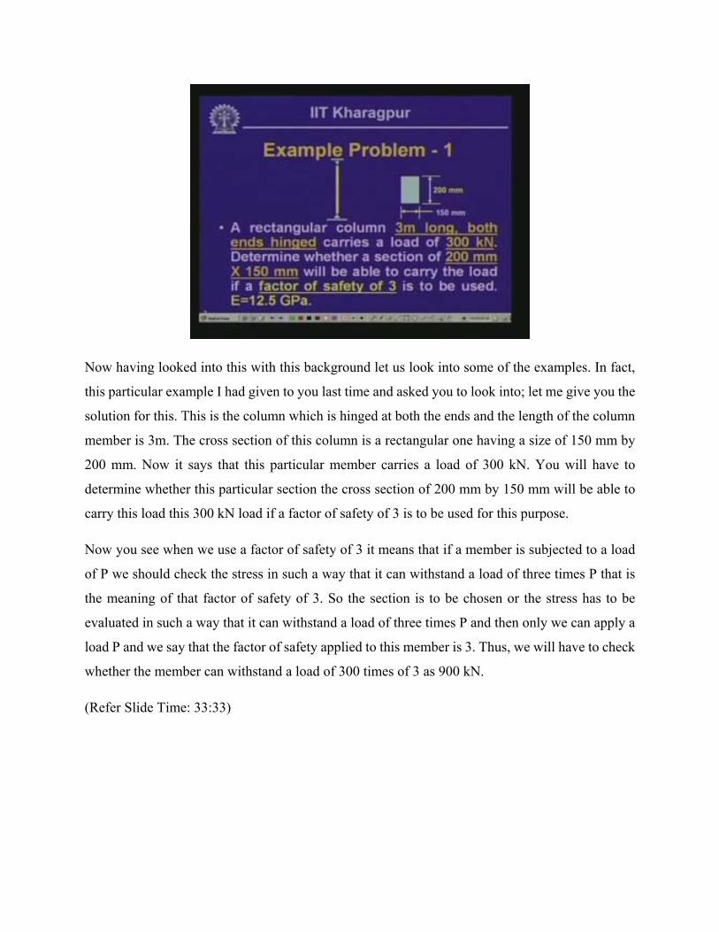
Now having looked into this with this background let us look into some of the examples. In fact,
this particular example I had given to you last time and asked you to look into; let me give you the
solution for this. This is the column which is hinged at both the ends and the length of the column
member is 3m. The cross section of this column is a rectangular one having a size of 150 mm by
200 mm. Now it says that this particular member carries a load of 300 kN. You will have to
determine whether this particular section the cross section of 200 mm by 150 mm will be able to
carry this load this 300 kN load if a factor of safety of 3 is to be used for this purpose.
Now you see when we use a factor of safety of 3 it means that if a member is subjected to a load
of P we should check the stress in such a way that it can withstand a load of three times P that is
the meaning of that factor of safety of 3. So the section is to be chosen or the stress has to be
evaluated in such a way that it can withstand a load of three times P and then only we can apply a
load P and we say that the factor of safety applied to this member is 3. Thus, we will have to check
whether the member can withstand a load of 300 times of 3 as 900 kN.
(Refer Slide Time: 33:33)
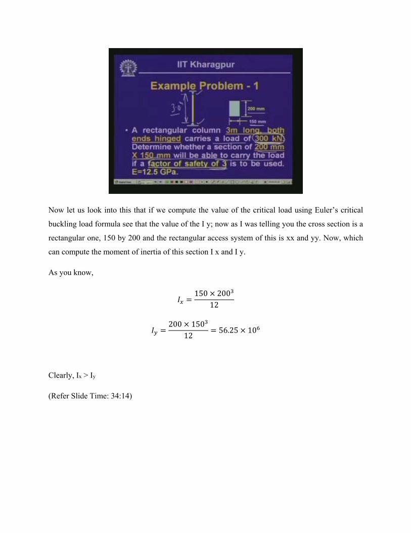
Now let us look into this that if we compute the value of the critical load using Euler’s critical
buckling load formula see that the value of the I y; now as I was telling you the cross section is a
rectangular one, 150 by 200 and the rectangular access system of this is xx and yy. Now, which
can compute the moment of inertia of this section I x and I y.
As you know,
150 20012
200 15012
56.25 10
Clearly, Ix > Iy
(Refer Slide Time: 34:14)
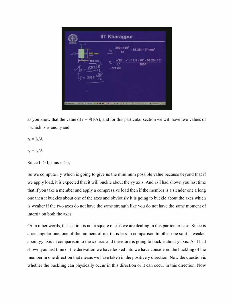
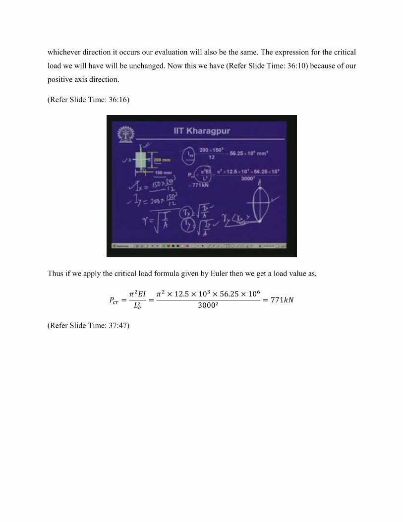
as you know that the value of r = √(I/A); and for this particular section we will have two values of
r which is rx and ry and
rx = Ix/A
ry = Iy/A
Since Ix > Iy, thus rx > ry
So we compute I y which is going to give us the minimum possible value because beyond that if
we apply load, it is expected that it will buckle about the yy axis. And as I had shown you last time
that if you take a member and apply a compressive load then if the member is a slender one a long
one then it buckles about one of the axes and obviously it is going to buckle about the axes which
is weaker if the two axes do not have the same strength like you do not have the same moment of
intertia on both the axes.
Or in other words, the section is not a square one as we are dealing in this particular case. Since is
a rectangular one, one of the moment of inertia is less in comparison to other one so it is weaker
about yy axis in comparison to the xx axis and therefore is going to buckle about y axis. As I had
shown you last time or the derivation we have looked into we have considered the buckling of the
member in one direction that means we have taken in the positive y direction. Now the question is
whether the buckling can physically occur in this direction or it can occur in this direction. Now
whichever direction it occurs our evaluation will also be the same. The expression for the critical
load we will have will be unchanged. Now this we have (Refer Slide Time: 36:10) because of our
positive axis direction.
(Refer Slide Time: 36:16)
Thus if we apply the critical load formula given by Euler then we get a load value as,
12.5 10 56.25 103000
771
(Refer Slide Time: 37:47)

As I was telling you that we will have to apply a factor of safety of 3 to this particular member and
thereby to have a 300 kN load.
P = 3 x 300 = 900 kN
Since we find that using Euler’s critical load formula the critical load is 771 kN which is less than
900 kN then this particular section will not be appropriate to apply a load of 300 kN with a factor
of safety of 3. So, to fulfill these two aspects; that means we will have to apply a load of 300 kN
with a factor of safety 3 will not be appropriate for this section or this section will not be able to
carry that load.
Now if you have to satisfy that that means you have to have 300 kN load on the member with a
factor of safety of 3 naturally then you will have to change the cross-sectional area, you will have
to go for higher cross-sectional area so that you can satisfy this particular criteria.
(Refer Slide Time: 38:23)

Well, let us look into another example and this particular example is a steel column of length 4m
and the ends of this particular column is fixed; both the ends are fixed. Now what is the minimum
length of the column for Euler’s formula to be applicable?
First of all we have to find out, though it is given that the length of the column member is 4m we
will have to find out the length for which we can apply the Euler’s critical load formula for such
situation and the member property is given as r, e of this is 200 Gpa Giga Pascal, the stress at the
proportionality limit is equals to 200 MPa, the yield stress of the material is 250 MPa and the
values of the radius of the direction about x and y axis rx is 180 and ry is 30 mm as it is expected
that the moment of inertia about y axis is less than the moment of inertia about x axis and thereby
the value of the radius direction about y axis is less than the radius of direction about x axis and
the value of the moment of inertia about y axis is given, the cross-sectional area of this particular
member is given.
(Refer Slide Time: 39:43)

Now the question is let us first find out that what is the value of the limiting length up to which
the Euler’s critical buckling load formula can be applied.
(Refer Slide Time: 40:01)
Now the value of e is given as 200 GPa, the stress at the proportional limit is given as 200 MPa;
now, from the critical stress expression that σcr is,

30200 10200
2.98
That means this is the minimum length that is needed for the member so that we can apply the
Euler’s critical buckling load formula. And mind that this is the effective length Le.
Now here (Refer Slide Time: 41:07) the member which we have considered is a fixed ended
member and thereby as we have seen that for a fixed ended member the critical load is equals to 4
π2 EI/L2 and thereby K=0.5.
For 4m length here, effective length it is going to be equals to 2m.
So effective length then in this particular case is equals to 2m and this (Refer Slide Time: 41:43)
being less than the length the minimum length we need thereby we cannot apply the Euler’s critical
buckling load formula.
Therefore, as you can see that limiting Le/r, where r = 30
Limiting Le/r =2980/30= 99
Actual Le/r =2000/30= 67
Now this value is less than the limiting Le/r value and therefore Euler’s critical load formula will
not give us the value of the critical load. So the options what we have is to look into that if this
member fails by the yielding that means it reaches to the yield stress value then the value the of
critical load will be the yield stress multiplied by the cross-sectional area which gives us a load of
2318 kN.
Now, if we consider this in the intermediate range that means it may fail in combination of the
buckling and the yielding, neither in the buckling range because we cannot apply the Euler’s load
formula and on the short column range where it goes to the yielding that is σ y times A the other
limiting value, now if we consider that it fails in the combination of the buckling and yielding then

it comes in the category of intermediate column unless we look into what is the critical load we
get if we use Rankine’s formula for evaluating the critical load.
Now the critical load which we get corresponding to the rankines formula,
250 9272
1 2502 10
200030
1483
(Refer Slide Time: 44:06)
Now as you can see that if we go up to the yield stress level or up to the crossing level then the
load which we can apply is this; and if we consider that the column might fail since the Le/r value
which we have got the actual Le/r we have obtained less than the limiting value there is a possibility
that the member is going to fail in the combination of the buckling and the yielding and thereby
we need to limit ourselves to a load of 1483 so the maximum load that we can apply is equals to
1483 so that the member does not fail either by buckling or by yielding or in combination of the
two.
This is the limiting load in this particular case. For this particular member as it has been said what
is the minimum length of the column for Euler’s formula to be applicable is as we have seen is
2.98m and mind that its effective length is 2.98m so in this particular case hence it is fixed onto its
column and as we seen for fixed ended column member the value of the effective length coefficient
is half that means we will have to have a column length of 2.98 times 2 that means around 6m
length you need for a fixed ended column member where we can apply the Euler’s column
buckling formula. Or else we will have to go for either the short column formula which is the yield
stress multiplied by the area or by the Rankine’s formula which is for the intermediate column.
(Refer Slide Time: 45:54)
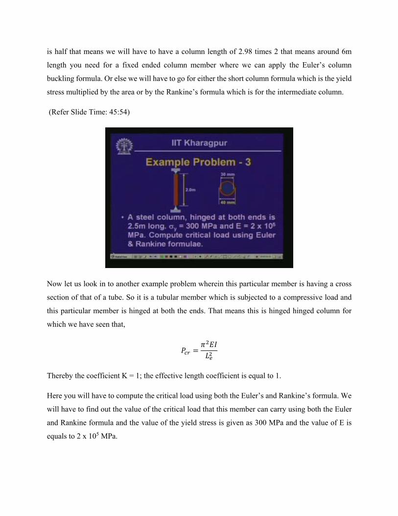
Now let us look in to another example problem wherein this particular member is having a cross
section of that of a tube. So it is a tubular member which is subjected to a compressive load and
this particular member is hinged at both the ends. That means this is hinged hinged column for
which we have seen that,
Thereby the coefficient K = 1; the effective length coefficient is equal to 1.
Here you will have to compute the critical load using both the Euler’s and Rankine’s formula. We
will have to find out the value of the critical load that this member can carry using both the Euler
and Rankine formula and the value of the yield stress is given as 300 MPa and the value of E is
equals to 2 x 10⁵ MPa.

So let us look into that what will be the critical Le/r. This being a tubular member as you know
that if we compute the value of the moment of inertia and the cross-sectional area,
6440 30 8.59 10
440 30 549.8
(Refer Slide Time: 47:15)
(Refer Slide Time: 47:19)
Now if we compute the value of the radius of gyration,
8.59 10549.8
12.5
Here,
250012.5
200
Limiting value of the Le/r
2 10300
81
Now since this actual Le/r is higher than the limiting Le/r so we can apply Euler’s critical buckling
load formula for evaluating the critical load in the member.
2 10 8.59 102500
27.13
Now if we use Rankine’s critical buckling load formula then we get,
300 549.8
1 3002 10
250012.5
23.3
Now you see that we have now two values of the critical load: one is corresponding to the Euler’s
critical buckling load and another one is corresponding to Rankine’s critical buckling load.
(Refer Slide Time: 50:34)
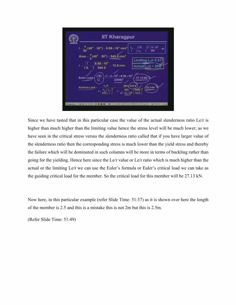
Since we have tasted that in this particular case the value of the actual slenderness ratio Le/r is
higher than much higher than the limiting value hence the stress level will be much lower; as we
have seen in the critical stress versus the slenderness ratio called that if you have larger value of
the slenderness ratio then the corresponding stress is much lower than the yield stress and thereby
the failure which will be dominated in such columns will be more in terms of buckling rather than
going for the yielding. Hence here since the Le/r value or Le/r ratio which is much higher than the
actual or the limiting Le/r we can use the Euler’s formula or Euler’s critical load we can take as
the guiding critical load for the member. So the critical load for this member will be 27.13 kN.
Now here, in this particular example (refer Slide Time: 51:37) as it is shown over here the length
of the member is 2.5 and this is a mistake this is not 2m but this is 2.5m.
(Refer Slide Time: 51:49)

Well, let us look into another example wherein we have a member which is made out of timber,
the cross section of which is a 50 mm by 100 mm rectangular one and length of the member is
1.2m. Now this particular member is used as a cantilever column; the value of e is given as 10 GPa
10 Giga Pascal and the stress at the proportionality limit is 30 MPa; we will have to determine the
largest axial load that this member can carry with a factor of safety of 2.
Now if you look into that, that the cross section of this member is a rectangular one having a size
of 50 mm by 100 mm, the length of the member is 1.2m and this is a cantilever column; now the
meaning of a cantilever column is that it is fixed at one end and is free at the other and this is
subjected to a compressive load P. So we will have to find out how much of load P we can apply
to this particular member having this particular section so that we can have a factor of safety of 2.
You keep this aspect in mind that will have to impose a factor of safety of 2 and we will have to
decide about what P load we can apply on this member.
(Refer Slide Time: 53:19)

Now, if we look into the cross section of this; as we have seen earlier for this rectangular cases
you have the xx and the yy at the two rectangular axis system and the width of the member let us
consider as 50 and depth as 100 mm so we can compute the value of I x and I y and as you know,
50 10012
100 5012
Since Iy < Ix, thereby ry < rx for this particular section.
100 5012 50 100
14.43
For this if we compute the value of the length of the member is equals to 1.2m and since this is a
cantilever member we have seen that for a cantilever member,
Pcr = π2EI/4L2, thereby the effective length coefficient, K = 2;
So Le = 2400mm
10 10 100 5012 2400
214.2
(Refer Slide Time: 55:30)

Now as it has been indicated that we will have to find the load in terms of a factor of safety of 2.
That means you will have to apply a load P in such a way that you can achieve a factor of safety
of 2 that means if we apply a load of twice P the member should be in a position to withstand that
stress. So, the maximum load that should be applied or it should be limited to is half the actual
load because this critical load which we compute from Euler’s critical load formula is not with any
factor of safety so we will have to impose the factor of safety to this. So, if we divided this load
by 2 the factor of safety value the load comes as 107.1 kN. So the maximum load that you can
apply on this particular member is equal to 107.1 kN.
Now if we apply a load higher than this 107.1 the wen will find that the member may fail by
buckling. But the question is that we have applied a factor of safety of 2 so even in this particular
case even if we exceed by this it may not fail immediately unless we have some other effect on
this member which can cause the failure on the member.
(Refer Slide Time: 56:56)
Well, then to summarize; in this particular lesson we have looked into some aspects of the previous
lesson. As we have seen, in previous lesson we have discussed about the Euler’s critical buckling
load formula and in this particular lesson we have seen what are the limitations of Euler’s critical
buckling load formula and also what are the different values of K which we have termed as the
coefficient of the effective length for different support conditions of the member which are either
1 or 2 or 0.7 or 0.5 depending upon different conditions we have.
Also, we have looked in at the concept of critical compressive stress in column members. We have
discussed about the Rankine’s formula of critical buckling load which are applicable for
intermediate columns and we have looked into some examples for evaluating critical loads in
different types of columns.
(Refer Slide Time: 58:03 - 58:45)

Now with this lesson we will come to the concluding part of this particular module which is on
stability of columns. Stability of columns basically we had two lessons. In the previous lesson we
had introduced the concept of stability the buckling and thereby we discussed about the Euler’s
critical load formula which are applicable for columns. In this particular lesson we looked into
what are the different phases of column; the short column, the long column and the intermediate
columns and then the critical load corresponding to the intermediate column and then we have
looked into the formula which is applicable for evaluating the critical load in intermediate column
given by Rankine.
(Refer Slide Time: 58:48-59:10)

Now these are the two lessons which we had and consequently we had looked into some examples
which can be evaluated using this formula. Now the questions set for you are this.
What is the effective length of a cantilever column?
What is intermediate column and how is it different from long or short column?
And what is Rankine constant? It is dependent on which parameters?
We will look into this; you will get the answers in these two lessons itself. The answers for this
will be given in the next lesson, thank you.