strengthening of deteriorating decks of highway bridges in
TRANSCRIPT

Final Report
FHWA/IN/JTRP-2001/15
Strengthening of Deteriorating Decks of Highway Bridges in Indiana Using FRPC
by
Elisa D. Sotelino Associate Professor
School of Civil Engineering Purdue University
Ming-Hung Teng
Research Assistant School of Civil Engineering
Purdue University
Joint Transportation Research Program Project No. C-36-56EEE
File No. 7-4-56 SPR-2490
In Cooperation with the Indiana Department of Transportation
and the Federal Highway Administration
Purdue University West Lafayette, Indiana
November 2001
TECHNICAL REPORT STANDARD TITLE PAGE 1. Report No.
2. Government Accession No.
3. Recipient's Catalog No.
FHWA/IN/JTRP-2001/15
4. Title and Subtitle Strengthening of Deteriorating Decks of Highway Bridges in Indiana Using FRPC
5. Report Date November 2001
6. Performing Organization Code
7. Author(s) Elisa Sotelino and Ming-Hung Teng
8. Performing Organization Report No. FHWA/IN/JTRP-2001/15
9. Performing Organization Name and Address Joint Transportation Research Program 1284 Civil Engineering Building Purdue University West Lafayette, Indiana 47907-1284
10. Work Unit No.
11. Contract or Grant No.
SPR-2490 12. Sponsoring Agency Name and Address Indiana Department of Transportation State Office Building 100 North Senate Avenue Indianapolis, IN 46204
13. Type of Report and Period Covered
Final Report
14. Sponsoring Agency Code
15. Supplementary Notes Prepared in cooperation with the Indiana Department of Transportation and Federal Highway Administration. 16. Abstract
Many industries, such as the aerospace and the automotive industries have successfully used Fiber Reinforced Polymer Composites (FRPC). These types of composite materials offer significant advantages over conventional civil engineering materials, such as concrete and steel. This is due to their chemical and corrosion resistance, lightweight, and high strength, which make them attractive for the rehabilitation of civil infrastructures. The objective of this research project is to study the feasibility of using of FRP as a retrofit or construction material for bridge decks. This has been accomplished by means of a synthesis study. This study included a comprehensive literature review of externally bonded FRPC strengthening systems and of the current state of knowledge on technologies involved in the design and construction of FRPC bridge decks, and a web-based survey of other state Departments of Transportations (DOTs) on their use of FRPC materials for bridge decks.
17. Key Words FRP, composites, strengthening, bridge decks, retrofit, fiber reinforced polymers
18. Distribution Statement No restrictions. This document is available to the public through the National Technical Information Service, Springfield, VA 22161
19. Security Classif. (of this report)
Unclassified
20. Security Classif. (of this page)
Unclassified
21. No. of Pages
93
22. Price
Form DOT F 1700.7 (8-69)
25-1 11/01 JTRP-2001/15 INDOT Division of Research West Lafayette, IN 47906
INDOT Research
TECHNICAL Summary Technology Transfer and Project Implementation Information
TRB Subject Code: 25-1 Bridge Design and Performance November 2001 Publication No.: FHWA/IN/JTRP-2001/15, SPR-2490 Final Report
Strengthening of Deteriorating Decks of Highway Bridges in Indiana Using FRPC
Introduction The service life of bridges is often
reduced due to the corrosion of steel reinforcing bars in bridge decks and to the cracking caused by loading in excess to the original design values due to increased traffic volumes. In Indiana, numerous bridges are in need of upgrading or rehabilitation. Current upgrading practices include replacing the part of deteriorated portion of the deck structure by patching damaged areas or replacing the whole deck structure. Both of these practices have drawbacks. The first is time-consuming and provides only a short-term solution, while the latter is expensive and causes severe traffic disruption. Therefore, alternative solutions should be devised for the rehabilitation and upgrading of deteriorated bridge decks in Indiana.
Many industries, such as the aerospace and the automotive industries have successfully used Fiber Reinforced Polymer Composites (FRPC). These types of composite materials offer significant advantages over conventional civil engineering materials, such as concrete and steel. This is due to their chemical and corrosion resistance, lightweight, and high strength, which make them attractive for the rehabilitation of civil infrastructures.
Strengthening of Reinforced Concrete (RC) structures by bonding external steel plates and composite plates or sheets is an
effective method for improving structural performance under both service and ultimate load conditions. A main disadvantage of using steel plates is the potential for corrosion at the epoxy/steel interface with consequent reduction in bond strength when exposed to harsh environments. Composite plates or sheets, on the other hand, offer several advantages over their steel counterparts, such as ease bondage to irregular surfaces, lightweight, etc.
FRPC have been used in the replacement of deficient bridge decks. Studies of the feasibility and long-term performance of this type of application have been conducted. These studies have concluded that not only FRPC decks should be considered as an alternative to conventional reinforced concrete decks; they have a number of advantages over the latter. In particular, their ease of construction should be highlighted: instead of weeks only a few days are required for their successful installation and consequently, traffic disruptions are minimized. The objective of this research project is to study the feasibility of using of FRP as a retrofit or construction material for bridge decks. This has been accomplished by means of a comprehensive literature review of externally bonded FRPC strengthening systems and of the current state of knowledge on

25-1 11/01 JTRP-2001/15 INDOT Division of Research West Lafayette, IN 47906
technologies involved in the design and construction of FRPC bridge decks. In addition, valuable information has been obtained through a web-based survey of other
state Departments of Transportations (DOTs) on their experience with FRPC materials for bridge decks.
Findings The results from the literature
review indicate that by externally bonding FRP plates (or sheets) and/or rods provide excellent retrofitting mechanisms to increase deck strength as well as stiffness of aging or deteriorated structures. The advantages of this retrofitting method include reduced labor costs, minimum shutdown time/cost and traffic disruption, and minimal maintenance requirements. From the literature review, it was found that the values of such the increase in stiffness and strength varied for the different field applications. However, in all cases such an increase was observed. Furthermore, it was also found that the benefits of such a retrofitting system do not change with time.
A number of demonstration projects that studied FRP bridge deck panels have been conducted countrywide. These projects range from small-scale pedestrian bridges to large-scale highway bridges as well as from deck replacement to bridges made entirely of composite materials. Most of the studies report that their FRP applications are performing very well. In fact, some of these applications are now 3 or 4 years old and continue to show excellent performance. In all cases, it is reported that the installation time is significantly reduced when compared to conventional reinforced concrete decks.
The experience of other state DOTs in the use of FRP as a retrofit and as a
construction material for bridge decks was investigated by means of a web-based survey. All 50 state DOTs were contacted and 34 responded the survey. Of the responding DOTs, 23 responded that they have used FRP for bridge desk rehabilitation and/or installed FRP bridge decks. The major reasons provided by these states for adopting FRP materials were their excellent strength, lightweight, and durability. Most of the states using FRP as a material for bridge deck rehabilitation reported that its main use was to strengthen and upgrade damaged bridge decks. Eight states responded that they had replaced a reinforced concrete bridge deck by a FRP bridge deck. Based on their experience, these DOTs have not observed any problems with their FRP application. Twenty state DOTs have responded that they are considering using FRP in the future. Most of them plan to utilize FRP as a strengthening/upgrading system.
The results from the literature review and DOT survey indicate that FRP materials have been successfully used in civil infrastructure applications, and in particular for bridge deck strengthening and replacement. It also appears, from the results of this study that the use of FRP in bridges is likely to continue and potentially become a mainstream material in the near future.
Implementation The current state of knowledge of
FRP materials as a construction material for civil infrastructure indicates that it can be successfully used in many types of applications. The present study focuses in their use for bridge decks. In order to further benefit from this technology, Indiana
must become part of the increasing research efforts in this area. Therefore, it is strongly recommended that a demonstration project be developed in this state. With this in mind, a proposal has been developed and submitted to the FHWA Innovative Bridge Research and Construction (IBRC) program.

25-1 11/01 JTRP-2001/15 INDOT Division of Research West Lafayette, IN 47906
In the proposed project, the three main spans of a bridge deck in Tippecanoe County will be replaced by 8” FRP deck panels. The scope of this project includes the evaluation and design of FRP bridge deck panels to meet current code
requirements. It also involves the reconstruction of an existing bridge deck using the innovative FRP deck panels. The monitoring of the performance of the developed application will also be part of the proposed IBRC project.
Contacts For more information: Prof. Elisa Sotelino Principal Investigator School of Civil Engineering Purdue University West Lafayette IN 47907 Phone: (765) 494-2228 Fax: (765) 496-1105
Indiana Department of Transportation Division of Research 1205 Montgomery Street P.O. Box 2279 West Lafayette, IN 47906 Phone: (765) 463-1521 Fax: (765) 497-1665 Purdue University Joint Transportation Research Program School of Civil Engineering West Lafayette, IN 47907-1284 Phone: (765) 494-9310 Fax: (765) 496-1105
TABLE OF CONTENTS
1. Introduction
1.1. Background .................................................................................................. 1
1.2. Objective ...................................................................................................... 3
1.3. Organization of the Report ........................................................................... 3
2. FRP as External/Internal Retrofits for Bridge Decks
2.1. Introduction .................................................................................................. 5
2.2. Literature Review ......................................................................................... 6
2.3. Manufacturers of External FRP Reinforcement Systems for Bridge
Decks ......................................................................................................... 17
3. FRP Bridge Decks
3.1. Introduction .................................................................................................. 21
3.2. Literature Review.......................................................................................... 22
3.3. FRP Bridge Deck Manufacturers ................................................................. 47
4. Survey of State DOTs
4.1. Introduction .................................................................................................. 53
4.2. Summary of State DOTs Responses ............................................................ 54
4.2.1. General .......................................................................................... 54
4.2.2. FRP Bridge Decks ........................................................................ 57
4.2.3. FRP Retrofits for Bridge Decks .................................................... 59

5. Summary of Findings, Conclusions, and Recommendations
5.1. Summary ...................................................................................................... 71
5.1.1. FRP Retrofits for Bridge Decks Summary ................................... 71
5.1.2. FRP Bridge Decks Summary......................................................... 72
5.1.3. Summary of Survey of State DOTs .............................................. 73
5.2. Conclusions .................................................................................................. 74
5.3. Recommendations ........................................................................................ 75
List of References ................................................................................................... 76
Appendix A: Short Survey .................................................................................... 80
Appendix B: Detailed Survey ................................................................................ 84
Appendix C: IBRC proposal …………………………………………………….. 90
1
CHAPTER 1. Introduction
1.1 Background
The service life of bridges is often reduced due to the corrosion of steel reinforcing bars in
bridge decks and to the cracking caused by loading in excess to the original design values due to
increased traffic volumes. In Indiana, numerous bridges are in need of upgrading or
rehabilitation. Current upgrading practices include replacing the part of deteriorated portion of
the deck structure by patching damaged areas or replacing the whole deck structure. Both of
these practices have drawbacks. The first is time-consuming and provides only a short-term
solution, while the latter is expensive and causes severe traffic disruption. Therefore, alternative
solutions should be devised for the rehabilitation and upgrading of deteriorated bridge decks in
Indiana.
Many industries, such as the aerospace and the automotive industries have successfully used
Fiber Reinforced Polymer Composites (FRPC). These types of composite materials offer
significant advantages over conventional civil engineering materials, such as concrete and steel.
This is due to their chemical and corrosion resistance, lightweight, and high strength, which
make them attractive for the rehabilitation of civil infrastructures.
Strengthening of Reinforced Concrete (RC) structures by bonding external steel plates and
composite plates or sheets is an effective method for improving structural performance under
both service and ultimate load conditions. A main disadvantage of using steel plates is the
potential for corrosion at the epoxy/steel interface with consequent reduction in bond strength
when exposed to harsh environments. Other disadvantages are transportation, storage,
installation difficulties as well as increase to the structure self-weight. Composite plates or
2
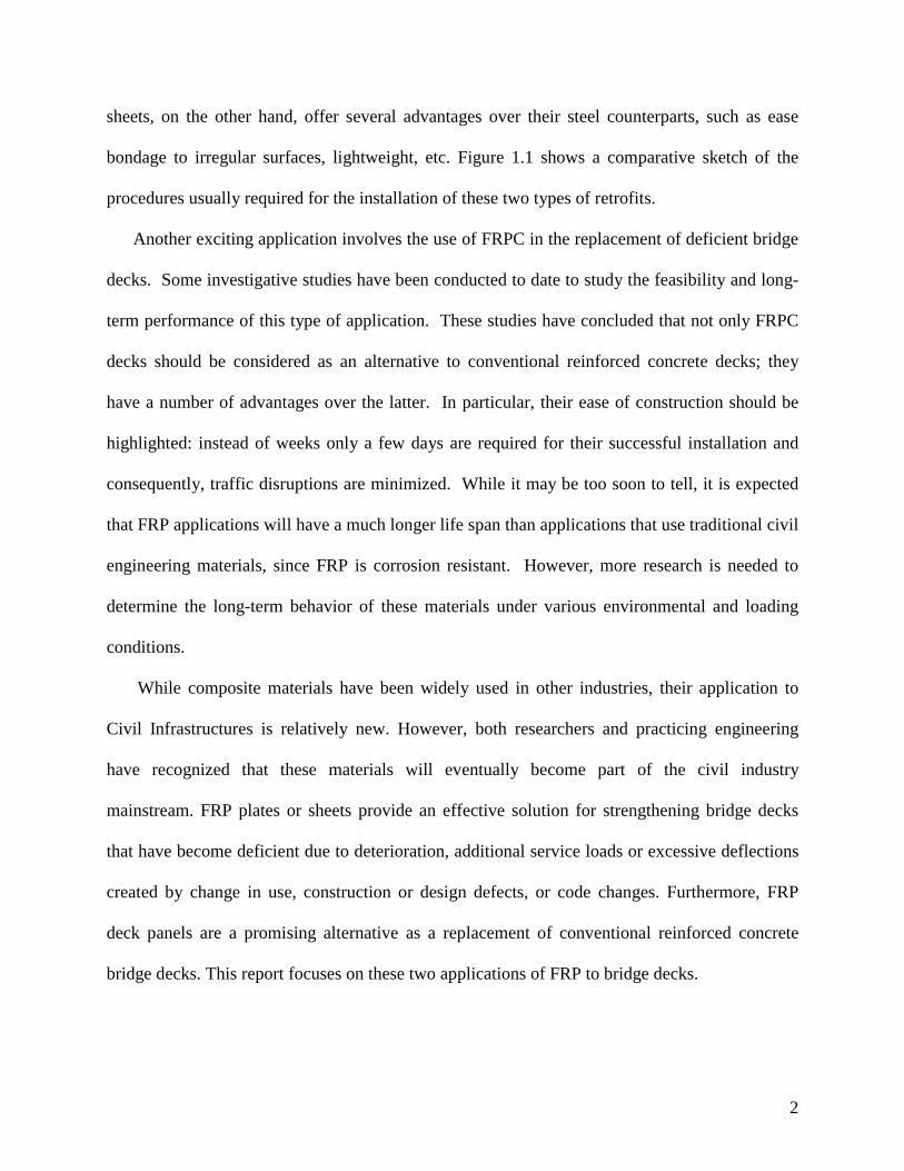
sheets, on the other hand, offer several advantages over their steel counterparts, such as ease
bondage to irregular surfaces, lightweight, etc. Figure 1.1 shows a comparative sketch of the
procedures usually required for the installation of these two types of retrofits.
Another exciting application involves the use of FRPC in the replacement of deficient bridge
decks. Some investigative studies have been conducted to date to study the feasibility and long-
term performance of this type of application. These studies have concluded that not only FRPC
decks should be considered as an alternative to conventional reinforced concrete decks; they
have a number of advantages over the latter. In particular, their ease of construction should be
highlighted: instead of weeks only a few days are required for their successful installation and
consequently, traffic disruptions are minimized. While it may be too soon to tell, it is expected
that FRP applications will have a much longer life span than applications that use traditional civil
engineering materials, since FRP is corrosion resistant. However, more research is needed to
determine the long-term behavior of these materials under various environmental and loading
conditions.
While composite materials have been widely used in other industries, their application to
Civil Infrastructures is relatively new. However, both researchers and practicing engineering
have recognized that these materials will eventually become part of the civil industry
mainstream. FRP plates or sheets provide an effective solution for strengthening bridge decks
that have become deficient due to deterioration, additional service loads or excessive deflections
created by change in use, construction or design defects, or code changes. Furthermore, FRP
deck panels are a promising alternative as a replacement of conventional reinforced concrete
bridge decks. This report focuses on these two applications of FRP to bridge decks.
3
1.2 Objective
The objective of this research project is to study the feasibility of using of FRP as a retrofit or
construction material for bridge decks. This has been accomplished by means of a
comprehensive literature review of externally bonded FRPC strengthening systems and of the
current state of knowledge on technologies involved in the design and construction of FRPC
bridge decks. In addition, valuable information has been obtained through a survey of other state
Departments of Transportations (DOTs) on their use of FRPC materials.
1.3 Organization of the Report
The organization of this report is provided next. In Chapter 2, a literature review on the
usage of FRPC strengthening systems for bridge decks is carried out. Chapter 3 presents the
current state of knowledge of FRP bridge decks. On both of these chapters, lists of relevant
manufacturers are provided. In Chapter 4, the results from the survey of all state DOTs are
summarized. Finally, in Chapter 5 recommendations are provided to INDOT for the
implementation of FRP decks in Indiana. In particular, the developed proposal submitted to the
FHWA Innovative Bridge Research and Construction (IBRC) program is given in Appendix C.
4
Figure 1.1 Installation of bridge deck retrofits (Emmons et al., 1998)
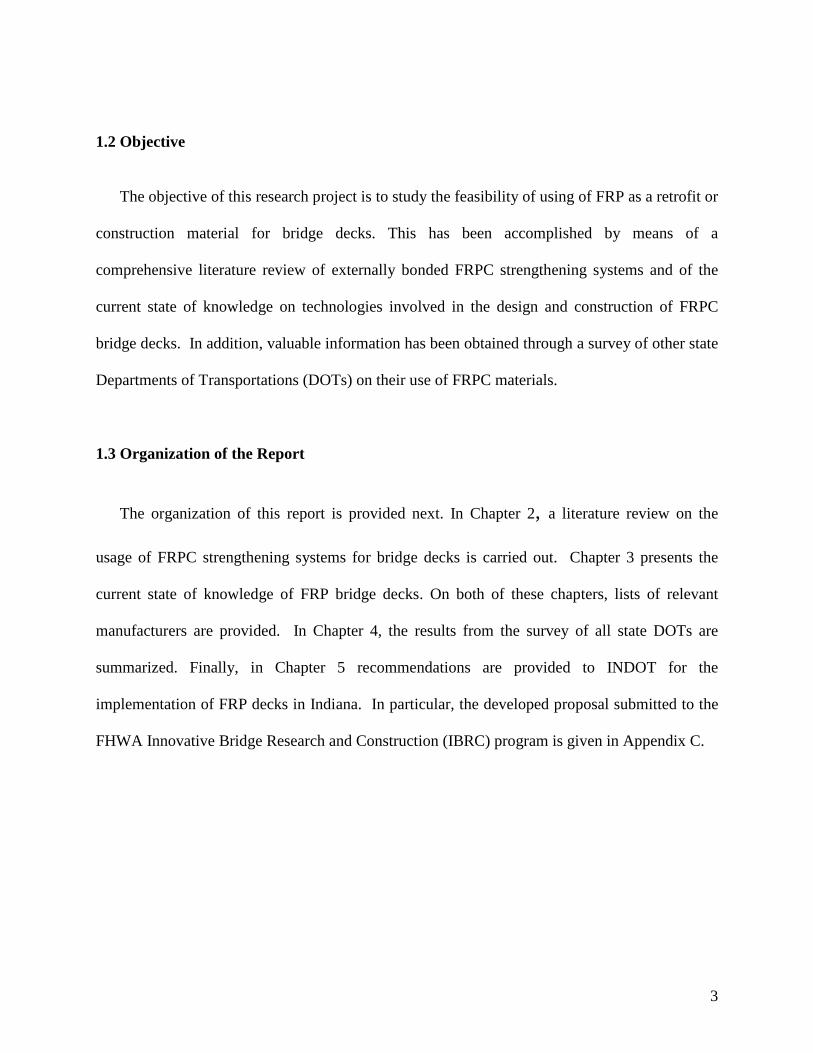
Figure 1.2 Components of the bonding material in FRPC sheets (Emmons et al., 1998)

5
Chapter 2. FRP as External/Internal Retrofits for Bridge Decks
2.1. Introduction
Advanced composite materials usually have two components: a reinforcing element and a
supporting matrix. The reinforcing element is, in general, much stiffer and stronger than the
matrix and as such, it is the load-carrying element. The matrix, on the other hand, provides
lateral support for the reinforcing element (Teng et al. 2000).
The matrix in Fiber Reinforced Polymer Composites (FRPC) consists of a polymer/resin
used as a binder material. It supports and separates the fibers, and it protects the fibers against
severe environmental conditions. Thermosetting polymer resins are the most common types of
matrix element. In particular, polyesters, epoxies and phenolics are the most frequently used
resins in civil engineering applications.
The FRPC reinforcing elements are used to provide the stiffness and strength to composite
materials. These reinforcing element materials, which are typically used in civil engineering
applications, are usually made of carbon (graphite), glass, and aramid (Kevlar) fibers. They are
imbedded in a resin matrix (e.g. epoxy resins) and they provide most of the tensile strength of the
composite just as steel does in reinforced concrete. FRPC is usually manufactured in a
continuously woven form with different lengths or directions in order to provide the best
performance for different applications.
Using externally bonded FRPC plates or rods to retrofit structures has been shown to be a
practical method for strengthening aging or deteriorated structures. The advantages of this
method include reduced labor costs, minimum shutdown time/cost and traffic disruption, and
minimal maintenance requirements. This chapter focuses on the application of this technology to

6
bridge decks. Section 2.2 provides a literature review of the published research in which FRP
has been used as a retrofit for deficient reinforced concrete bridge decks. In Section 2.3, the
different manufacturers of these types of FRP retrofits are provided.
2.2. Literature Review
Nanni (1995)
In this work, several applications of externally bonded FRP reinforcement of concrete
structures developed in Japan are discussed. According to the author, the function of these
retrofits depends on the type of application, i.e., it may be any combination of strengthening,
stiffening, crack arrest, or corrosion protection. In particular, two examples of bridge deck
retrofitting are highlighted. They are the Hata and Hiyoshikura bridges.
The Hata Bridge (Figure 2.1) is located in Kyushu Highway in Southern Japan. In this
application, FRP sheets were installed on the soffit of the cantilevered wing slab to provide the
needed additional capacity caused by the installation of a larger windbreak wall. This project
took was conducted in the spring of 1994.
Figure 2.1. Hata Bridge – Japan (Nanni, 1995)
7
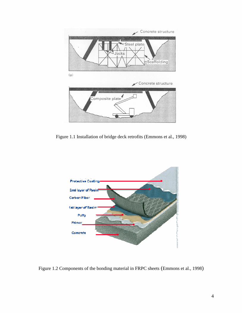
Two layers of carbon FRP (CFRP) were applied both parallel and perpendicular to the traffic
direction. In some critical locations three plies were used. The sheets were applied by roller
brushing the adhesive to the underside followed by the application of the FRP sheet, as shown in
Figure 2.2. The fiber were always oriented in the direction parallel to the long dimension of the
sheets, which were 50 cm wide and the length was cut to size. On-site loading test were
conducted to test the effectiveness of the strengthening method. More specifically, these tests
showed the strains were reduced considerably on the steel reinforcement.
Figure 2.2. Installation of FRP sheets on the soffit of the cantilevered slab of Hata Bridge
(Nanni, 1995)
In the spring of 1994, the deck of the Hiyoshikura Bridge located on the Tokando Highway
was in need of upgrading due to the increased traffic load and the presence of mapping cracks.
The bridge consisted of a reinforced concrete deck supported by steel girders. Instead of
replacing the deck, the cracks were sealed and FRP wraps were applied to the underside of the

8
deck for strengthening. More specifically, the area of soffit of the deck (164 m2 or 1760 ft2) was
covered with two layers of CFRP placed parallel and perpendicular to the traffic direction
(Figure 2.2).
In order to evaluate the developed application, strain gages were installed on steel reinforcing
bars on the underside of the deck. Running vehicle tests were conducted that showed that the
tensile strain in the steel reinforcement reduced by 30 to 40%.
Hoa et al. (1996)
In this work, the effect of environmental conditions, in particular temperature and moisture
effects, on structures repaired by externally bonding carbon/epoxy composite sheets is
investigated. Portland cement was used to cast concrete specimens. The proportion of cement:
sand: coarse aggregate was 1:2:3 in volume. The formwork was removed 24 hours after casting.
The curing time was 28 days at room temperature. The average cylinder strength of the concrete
after 28 days was 18 MPa.
Unidirectional graphite/epoxy composite sheets were used. The thickness of the composite
plates varied from 0.33 mm (3 layers) to 6 mm (45 layers).
Before bonding the FRP sheets to the concrete surfaces, these surfaces were prepared by: (a)
sandblasting until the aggregates were exposed; (b) washing with water and blasting it with air
for drying; and (c) cleaning with acetone. The preparation of the surfaces of the composite sheets
consisted of sanding with sand paper and then cleaning with acetone.
Both accelerated tests and long-term environmental tests were conducted on the developed
specimens. Two types of accelerated tests were performed. In one of them, the specimens were
immersed at room temperature for 60 days. In the other, hot-cold cycles were applied, i.e.,
9
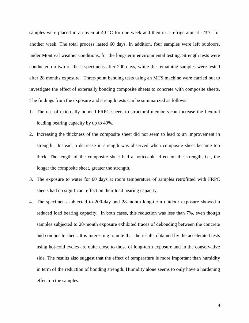
samples were placed in an oven at 40 °C for one week and then in a refrigerator at -23°C for
another week. The total process lasted 60 days. In addition, four samples were left outdoors,
under Montreal weather conditions, for the long-term environmental testing. Strength tests were
conducted on two of these specimens after 200 days, while the remaining samples were tested
after 28 months exposure. Three-point bending tests using an MTS machine were carried out to
investigate the effect of externally bonding composite sheets to concrete with composite sheets.
The findings from the exposure and strength tests can be summarized as follows:
1. The use of externally bonded FRPC sheets to structural members can increase the flexural
loading bearing capacity by up to 49%.
2. Increasing the thickness of the composite sheet did not seem to lead to an improvement in
strength. Instead, a decrease in strength was observed when composite sheet became too
thick. The length of the composite sheet had a noticeable effect on the strength, i.e., the
longer the composite sheet, greater the strength.
3. The exposure to water for 60 days at room temperature of samples retrofitted with FRPC
sheets had no significant effect on their load bearing capacity.
4. The specimens subjected to 200-day and 28-month long-term outdoor exposure showed a
reduced load bearing capacity. In both cases, this reduction was less than 7%, even though
samples subjected to 28-month exposure exhibited traces of debonding between the concrete
and composite sheet. It is interesting to note that the results obtained by the accelerated tests
using hot-cold cycles are quite close to those of long-term exposure and in the conservative
side. The results also suggest that the effect of temperature is more important than humidity
in term of the reduction of bonding strength. Humidity alone seems to only have a hardening
effect on the samples.
10
In conclusion, the authors have found that using hot-cold cycles is an effective method for
accelerated testing of the long-term performance of FRPC sheet retrofitted specimens. Finally,
they concluded that using externally bonded FRPC sheet can restore the load bearing capacity of
deficient specimens.
Arockiasamy et al. (1996)
In this study, two solid slabs 1219 mm x 305 mm x 4420 mm (48 in. x 12 in. x 14 ft. 6 in.)
and two voided slabs 1194 mm x 203 mm x 6553 mm (47 in. x 8 in. x 21 ft. 6 in.) were studied.
Both of these slabs were pre-cracked and then one of each type was reinforced with externally
bonded CFRP plates to evaluate the contribution of the retrofit to the strength and stiffness of the
slabs. The specimens were loaded to failure after complete cure of the adhesives.
From the tests, it was observed that failure mode of the retrofitted solid slab occurred by
crushing of concrete at midspan, while the control precracked slab failed at point of application
of the load. The results show that by retrofitting severely damaged solid slab with CFRP
laminates, improve significantly its flexural capacity (approximately 90% of the flexural capacity
of the uncracked slab). The retrofitted voided slab experienced a sudden and catastrophic failure.
This suggests that prior damage to the slab may have existed leading to local concrete crushing
failure. The retrofitted solid and voided slabs exhibit larger deflection than the control
precracked slabs at both service and ultimate loads. Crack patterns of the retrofitted slabs were
identical to those of the control slabs.
11
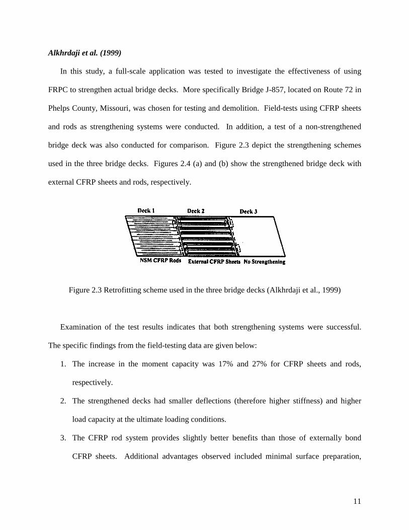
Alkhrdaji et al. (1999)
In this study, a full-scale application was tested to investigate the effectiveness of using
FRPC to strengthen actual bridge decks. More specifically Bridge J-857, located on Route 72 in
Phelps County, Missouri, was chosen for testing and demolition. Field-tests using CFRP sheets
and rods as strengthening systems were conducted. In addition, a test of a non-strengthened
bridge deck was also conducted for comparison. Figure 2.3 depict the strengthening schemes
used in the three bridge decks. Figures 2.4 (a) and (b) show the strengthened bridge deck with
external CFRP sheets and rods, respectively.
Figure 2.3 Retrofitting scheme used in the three bridge decks (Alkhrdaji et al., 1999)
Examination of the test results indicates that both strengthening systems were successful.
The specific findings from the field-testing data are given below:
1. The increase in the moment capacity was 17% and 27% for CFRP sheets and rods,
respectively.
2. The strengthened decks had smaller deflections (therefore higher stiffness) and higher
load capacity at the ultimate loading conditions.
3. The CFRP rod system provides slightly better benefits than those of externally bond
CFRP sheets. Additional advantages observed included minimal surface preparation,

12
rapid installation time, and ability of anchoring the reinforcement into adjacent RC
members.
(a) (b)
Figure 2.4 Strengthening schemes: (a) FRP sheets, (b) FRP rods (Alkhrdaji et al., 1999)
Rizkalla and Labossière (1999)
This article describes some projects in Canada that use FRP materials to strengthen bridge.
One of such projects consisted of the application of CFRP to “internally” strengthen a bridge
deck underneath the overlay. The developed application is shown in Figure 2.5. The structure is
referred to as the Country Hills Boulevard Bridge in Calgary, Alberta, Canada. The main reason
for the bridge strengthening was that it was found that its thin deck would overload under full
truck loading. The main considerations that lead to the decision to use such a retrofit, included
the fact that they did not wish to replace the whole deck (nondestructive alternative) and that
they wished to minimize traffic disruption. The procedures used in the development of this
application were:
1. CFRP strips were installed at 20 inches center to center.

13
2. The deck surface was rough. A layer of Sikadur 30 with sand aggregate was applied for
leveling purposes.
3. The CFRP strips were applied with epoxy after one day.
4. The excess epoxy in each strip was removed through rolling.
5. The surface of each strip was cleaned and sanded after one day.
6. A bonding agent was applied on the back surface of each strip four hours prior to the
installation of the overlay.
Figure 2.5 FRP strips applied on deck of the Country Hills Boulevard Bridge (Rizkalla and
Labossière, 1999)
Another project described in this article is the strengthening of the Ste-Émélie-de-l’Énergie
Bridge in Québec, Canada using FRP materials. The site preparation included a curing time of
the concrete used in the repair of four weeks. The composite strips were installed in eight days
over a period of three weeks. The CFRP strips were 50 mm (2 in) wide. The behavior was
monitored using strain gages, thermocouples, and optic fibers with Bragg sensors or Fabry-Perot

14
sensors. The Ministère de Transports performed loading test both prior and after the repair. The
goals of increasing the bending strength by 35% and the shear strength by 20% were achieved.
Taerwe and Mathys (1999)
In this article, the strengthening of damaged concrete structures using FRP is discussed. In
particular, the strengthening of the Tannberg Bridge in Austria is mentioned, in which CFRP
fabric strips were applied to the underside of the bridge deck as shown in Figure 2.6. Freyssinet
manufactured these sheets, which are referred to as TFC sheets. Details on the strengthening
scheme and on the performance of the developed scheme are not provided in this article.
Figure 2.6 Strengthening of the Tannberg Bridge, Austria (Taerwe and Mathys, 1999)
15
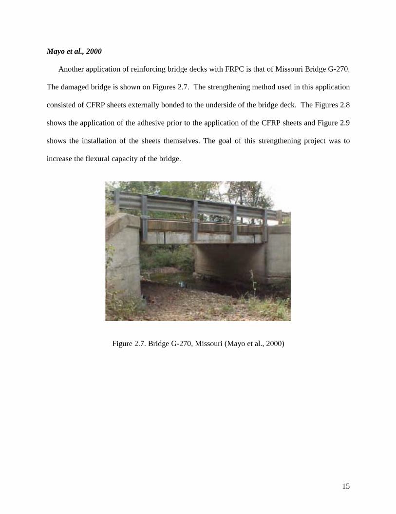
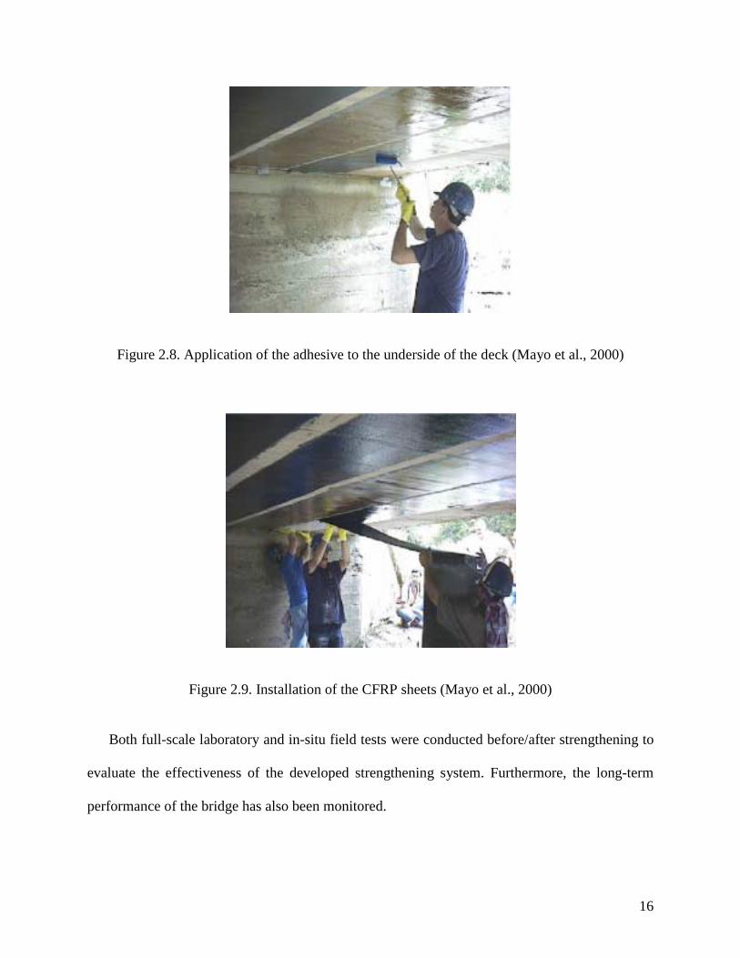
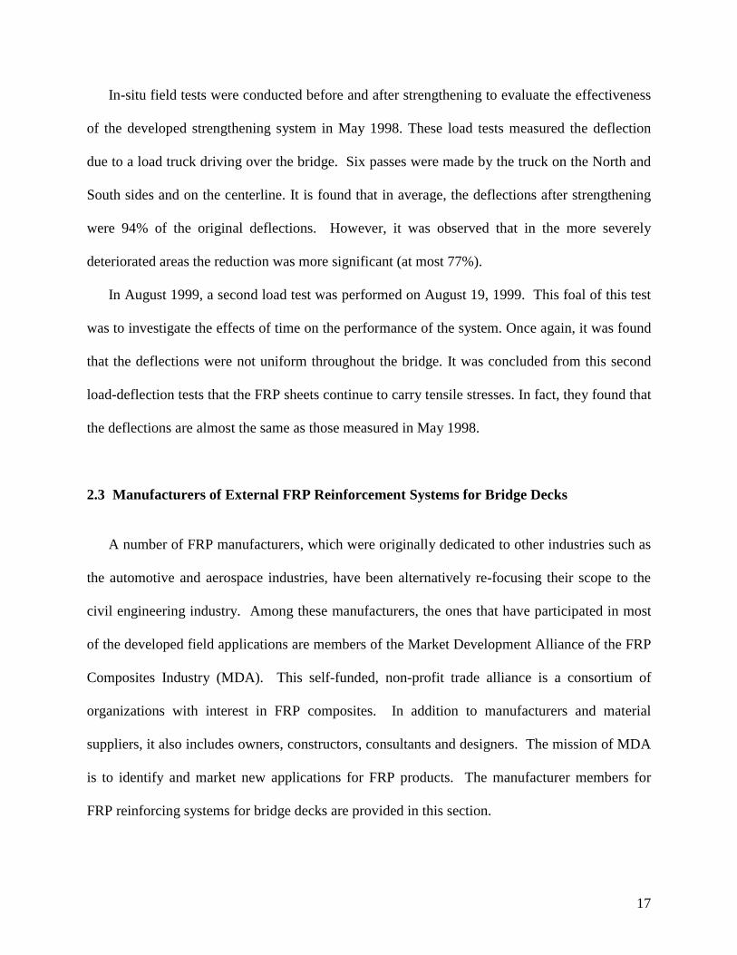
Mayo et al., 2000
Another application of reinforcing bridge decks with FRPC is that of Missouri Bridge G-270.
The damaged bridge is shown on Figures 2.7. The strengthening method used in this application
consisted of CFRP sheets externally bonded to the underside of the bridge deck. The Figures 2.8
shows the application of the adhesive prior to the application of the CFRP sheets and Figure 2.9
shows the installation of the sheets themselves. The goal of this strengthening project was to
increase the flexural capacity of the bridge.
Figure 2.7. Bridge G-270, Missouri (Mayo et al., 2000)
16
Figure 2.8. Application of the adhesive to the underside of the deck (Mayo et al., 2000)
Figure 2.9. Installation of the CFRP sheets (Mayo et al., 2000)
Both full-scale laboratory and in-situ field tests were conducted before/after strengthening to
evaluate the effectiveness of the developed strengthening system. Furthermore, the long-term
performance of the bridge has also been monitored.
17
In-situ field tests were conducted before and after strengthening to evaluate the effectiveness
of the developed strengthening system in May 1998. These load tests measured the deflection
due to a load truck driving over the bridge. Six passes were made by the truck on the North and
South sides and on the centerline. It is found that in average, the deflections after strengthening
were 94% of the original deflections. However, it was observed that in the more severely
deteriorated areas the reduction was more significant (at most 77%).
In August 1999, a second load test was performed on August 19, 1999. This foal of this test
was to investigate the effects of time on the performance of the system. Once again, it was found
that the deflections were not uniform throughout the bridge. It was concluded from this second
load-deflection tests that the FRP sheets continue to carry tensile stresses. In fact, they found that
the deflections are almost the same as those measured in May 1998.
2.3 Manufacturers of External FRP Reinforcement Systems for Bridge Decks
A number of FRP manufacturers, which were originally dedicated to other industries such as
the automotive and aerospace industries, have been alternatively re-focusing their scope to the
civil engineering industry. Among these manufacturers, the ones that have participated in most
of the developed field applications are members of the Market Development Alliance of the FRP
Composites Industry (MDA). This self-funded, non-profit trade alliance is a consortium of
organizations with interest in FRP composites. In addition to manufacturers and material
suppliers, it also includes owners, constructors, consultants and designers. The mission of MDA
is to identify and market new applications for FRP products. The manufacturer members for
FRP reinforcing systems for bridge decks are provided in this section.
18
The use of FRP materials to strengthen concrete structures can be traced to the 1950s,
however their use as an external reinforcement of concrete bridge structures began in 1980s
(MDA 2000). According to MDA’s report (MDA 2000), more than 1000 bridges (concrete
slab/steel girders) in Japan have been strengthened by bonding FRP sheets to the slab. In the
U.S., this technology has been widely used to retrofit columns for seismic upgrade. Of the
companies that specialize in the use of FRP sheets to retrofit bridge structures, the ones that have
used this technology to upgrade bridge decks are listed below.
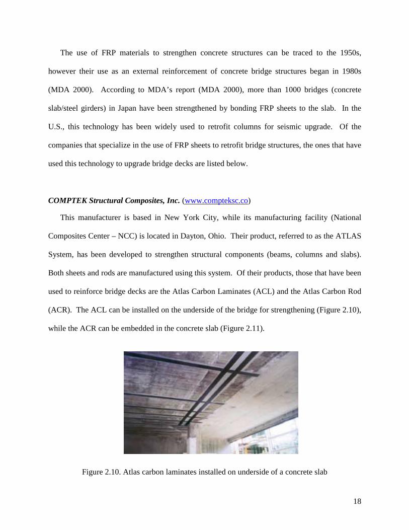
COMPTEK Structural Composites, Inc. (www.compteksc.co)
This manufacturer is based in New York City, while its manufacturing facility (National
Composites Center – NCC) is located in Dayton, Ohio. Their product, referred to as the ATLAS
System, has been developed to strengthen structural components (beams, columns and slabs).
Both sheets and rods are manufactured using this system. Of their products, those that have been
used to reinforce bridge decks are the Atlas Carbon Laminates (ACL) and the Atlas Carbon Rod
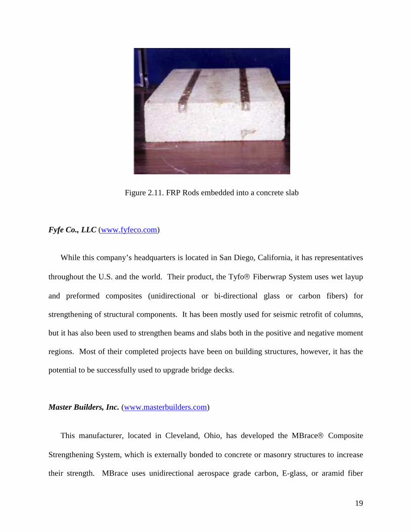
(ACR). The ACL can be installed on the underside of the bridge for strengthening (Figure 2.10),
while the ACR can be embedded in the concrete slab (Figure 2.11).
Figure 2.10. Atlas carbon laminates installed on underside of a concrete slab
19
Figure 2.11. FRP Rods embedded into a concrete slab
Fyfe Co., LLC (www.fyfeco.com)
While this company’s headquarters is located in San Diego, California, it has representatives
throughout the U.S. and the world. Their product, the Tyfo Fiberwrap System uses wet layup
and preformed composites (unidirectional or bi-directional glass or carbon fibers) for
strengthening of structural components. It has been mostly used for seismic retrofit of columns,
but it has also been used to strengthen beams and slabs both in the positive and negative moment
regions. Most of their completed projects have been on building structures, however, it has the
potential to be successfully used to upgrade bridge decks.
Master Builders, Inc. (www.masterbuilders.com)
This manufacturer, located in Cleveland, Ohio, has developed the MBrace Composite
Strengthening System, which is externally bonded to concrete or masonry structures to increase
their strength. MBrace uses unidirectional aerospace grade carbon, E-glass, or aramid fiber

20
fabrics embedded in engineered materials that include epoxy surface primers, putty fillers, and
high solids resins. One of their completed projects is the upgrade of the MoDOT Bridge G270 in
Iron County, MO (Figure 2.12) in May 1998. The MBrace system was applied to the underside
of the bridge’s deck to allow for a larger load rating.
Figure 2.12. MoDOT Bridge G270 (Iron County, MO)

21
Chapter 3. FRPC Bridge Decks 3.1. Introduction
Due to aging, environmentally induced degradation, poor initial construction, overloading,
and lack of maintenance, bridge components such as decks, superstructures, and columns may
become deficient. Nearly 40% of all highway bridges in the USA are classified as either
functionally or structurally deficient, and in approximately one-half of these bridges this
deficiency can be attributed to their decks (Hayes et al. 2000). It is estimated that a traditional
bridge deck lasts 35 years on average; however, in cold regions, such as the Midwest of the U.S.,
the life of a deck averages 10 years. This is because of the extensive use of de-icing salts during
winter months (Karbhari et al. 1997).
During the past decade, the use of fiber-reinforced polymer composites (FRPC) in civil
infrastructures has begun to receive significant attention by the civil engineering community.
This is because these materials offer significant advantages over conventional materials due to
their chemical and corrosion resistance, lightweight, and high strength. However, much of the
research carried out in this area has focused mainly in the use of these materials to retrofit
existing deficient structural components such as columns, beams, and slabs. However, an
exciting application involves the use of FRPC in the replacement of deficient bridge decks. This
section provides a summary of the research and manufacturing information available in this area.
Section 3.2 provides a literature review of the published research projects in which FRP deck
panels were developed. This literature review is organized chronologically, i.e., from older to
more recent publications. In Section 3.3, the different manufacturers of FRP bridge deck panels
are provided.
22
3.2. Literature Review
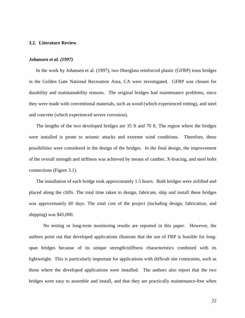
Johansen et al. (1997)
In the work by Johansen et al. (1997), two fiberglass reinforced plastic (GFRP) truss bridges
in the Golden Gate National Recreation Area, CA were investigated. GFRP was chosen for
durability and maintainability reasons. The original bridges had maintenance problems, since
they were made with conventional materials, such as wood (which experienced rotting), and steel
and concrete (which experienced severe corrosion).
The lengths of the two developed bridges are 35 ft and 70 ft. The region where the bridges
were installed is prone to seismic attacks and extreme wind conditions. Therefore, these
possibilities were considered in the design of the bridges. In the final design, the improvement
of the overall strength and stiffness was achieved by means of camber, X-bracing, and steel bolts
connections (Figure 3.1).
The installation of each bridge took approximately 1.5 hours. Both bridges were airlifted and
placed along the cliffs. The total time taken to design, fabricate, ship and install these bridges
was approximately 60 days. The total cost of the project (including design, fabrication, and
shipping) was $45,000.
No testing or long-term monitoring results are reported in this paper. However, the
authors point out that developed applications illustrate that the use of FRP is feasible for long-
span bridges because of its unique strength/stiffness characteristics combined with its
lightweight. This is particularly important for applications with difficult site constraints, such as
those where the developed applications were installed. The authors also report that the two
bridges were easy to assemble and install, and that they are practically maintenance-free when
23
compared to bridges made of conventional civil engineering materials, such as concrete, wood,
and steel.
Figure 3.1. 70-ft long FRP pedestrian bridge (Johansen et al. 1997)
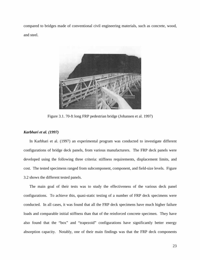
Karbhari et al. (1997)
In Karbhari et al. (1997) an experimental program was conducted to investigate different
configurations of bridge deck panels, from various manufacturers. The FRP deck panels were
developed using the following three criteria: stiffness requirements, displacement limits, and
cost. The tested specimens ranged from subcomponent, component, and field-size levels. Figure
3.2 shows the different tested panels.
The main goal of their tests was to study the effectiveness of the various deck panel
configurations. To achieve this, quasi-static testing of a number of FRP deck specimens were
conducted. In all cases, it was found that all the FRP deck specimens have much higher failure
loads and comparable initial stiffness than that of the reinforced concrete specimen. They have
also found that the “box” and “trapezoid” configurations have significantly better energy
absorption capacity. Notably, one of their main findings was that the FRP deck components
24
continued to carry load even when substantial cracking and fracture had occurred, i.e., no
catastrophic failure was observed.
Figure 3.2. Tested deck panel specimens (Karbhari et al. 1997)
Overall, they concluded that FRP decks are a suitable alternative to conventional civil
reinforced bridge decks. Furthermore, they found that these decks could be fabricated using
many different processes. Some related topics that were not addressed in this work include: the
response under dynamic loads, the behavior of the connections between deck and girders, and
deck and barrier and side rails, the effect of the different material properties between FRP and
existing substructure, and the long-term durability.
Chajes, M. et al. (1998)
The paper by Chajes, M. et al. (1998) discusses the evolution and status of three bridges
made of advanced composites in Delaware. In this research extensive monitoring through both
initial load testing and long-term monitoring programs were developed

25
The three bridges were selected such that they were incrementally more complex and had
more restrictive service requirements. These bridges were designed using the AASHTO LRFD
Bridge Design Specifications and factors taking into account deterioration of material properties
over time were used (for a life span of 75 years). Both strength and service limit states were
considered, including the effects of fatigue loading.
The first bridge, the Magazine Ditch Bridge, is a 22 m long, single-span, simply supported
bridge (Figure 3.3). It was installed on a private service road and it was completed on June 23,
1997. This bridge carries a small traffic volume, even though it is also traveled by heavily
loaded maintenance vehicles. The developed bridge is made of glass fiber reinforced polymer
(GFRP). A 45-mm wearing surface made of latex modified concrete was installed on the deck
surface. The installation of the bridge superstructure, including the edge girders and the GFRP
composite deck, was completed in a one day.
Figure 3.3. The Magazine Ditch Bridge (Chajes, M. et al. 1998)
26
Laboratory tests on sub-components and on a full-scale portion of the deck (1.2 m long by 6
m wide) were performed at the University of Delaware. The test program included the
application of AASHTO service and strength loads, and fatigue tests of up to 2,000,000 cycles.
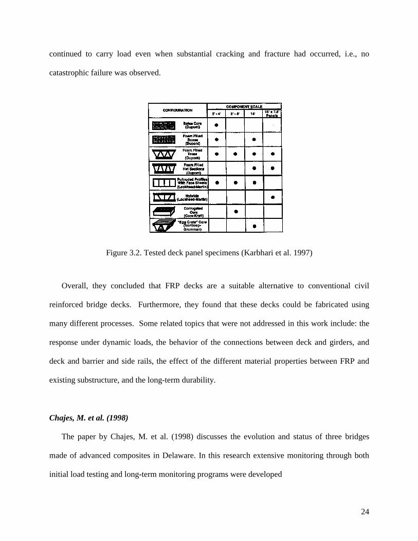
The second bridge, Bridge 1-351, replaced an existing bridge in the state of Delaware (Figure
3.4). The original bridge was a 9 m long by 12 m wide simply supported slab bridge. The
developed GFRP bridge is 9 m long by 8 m wide, with an all-composite deck.
Figure 3.4. Bridge 1-351 (Chajes, M. et al. 1998)
Laboratory tests conducted at the University of Delaware have shown that fatigue cycles (up
to 2,000,000 fatigue cycles) do not cause significant losses in strength and stiffness to the GFRP
deck. The design of this bridge wasimilar to that of an adjacent reinforced concrete bridge
design.
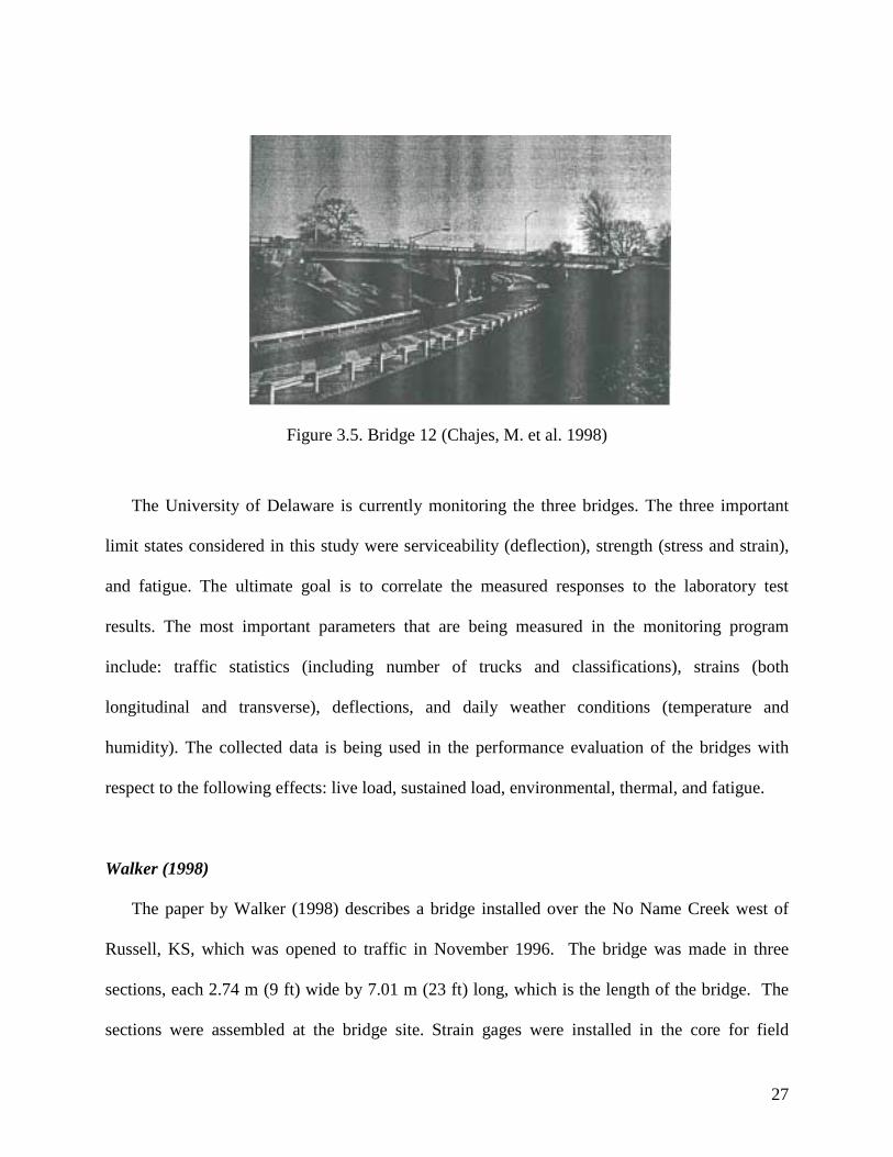
The third bridge, Bridge 12, is located in Rout 13 in Delaware (Figure 3.5). It represents a
typical highway bridge, since it has multiple spans, is a heavily traveled road, and carries large
volume of truck traffic. The scope of this project included the design, structural certification, sub
component testing, fabrication, construction, and monitoring and evaluation.
27
Figure 3.5. Bridge 12 (Chajes, M. et al. 1998)
The University of Delaware is currently monitoring the three bridges. The three important
limit states considered in this study were serviceability (deflection), strength (stress and strain),
and fatigue. The ultimate goal is to correlate the measured responses to the laboratory test
results. The most important parameters that are being measured in the monitoring program
include: traffic statistics (including number of trucks and classifications), strains (both
longitudinal and transverse), deflections, and daily weather conditions (temperature and
humidity). The collected data is being used in the performance evaluation of the bridges with
respect to the following effects: live load, sustained load, environmental, thermal, and fatigue.
Walker (1998)
The paper by Walker (1998) describes a bridge installed over the No Name Creek west of
Russell, KS, which was opened to traffic in November 1996. The bridge was made in three
sections, each 2.74 m (9 ft) wide by 7.01 m (23 ft) long, which is the length of the bridge. The
sections were assembled at the bridge site. Strain gages were installed in the core for field
28
monitoring. The bridge was designed to withstand standard highway traffic loads as specified by
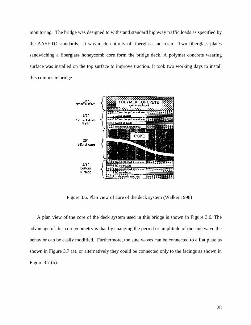
the AASHTO standards. It was made entirely of fiberglass and resin. Two fiberglass plates
sandwiching a fiberglass honeycomb core form the bridge deck. A polymer concrete wearing
surface was installed on the top surface to improve traction. It took two working days to install
this composite bridge.
Figure 3.6. Plan view of core of the deck system (Walker 1998)
A plan view of the core of the deck system used in this bridge is shown in Figure 3.6. The
advantage of this core geometry is that by changing the period or amplitude of the sine wave the
behavior can be easily modified. Furthermore, the sine waves can be connected to a flat plate as
shown in Figure 3.7 (a), or alternatively they could be connected only to the facings as shown in
Figure 3.7 (b).

29
(a)
(b)
Figure 3.7. Different core geometries (Walker 1998)
Lopez-Anido et al. (1998), GangaRao et al. (1999), GangaRao and Cairo (1999)
In these three papers, two demonstration projects are discussed that involve two advanced
composite bridges installed on secondary roads in West Virginia. These bridges are the Laurel
Lick Bridge (short-span FRP bridge) and the Wickwire Run Bridge (FRP deck on steel beams).
The West Virginia Department of Transportation Division of Highways (WVDOH) bridge
engineers were the lead participants in these efforts.
Both bridge decks were engineered using E-glass FRP. The composite deck cross-sectional
shape and fiber architecture was designed to withstand highway bridge loads while minimizing
the weight. The core of the decks consists of full-depth hexagons and half-depth trapezoids as
shown in Figure 3.8. The decks were built with a depth of 203 mm (8 in), since this is the typical
depth of concrete decks for highway bridges.
The authors point out that the Pultruded FRPC deck modules fabricated for these field
applications have some of the advantages of the pultrusion process, namely: its low labor and

30
operating costs, minimal production of material waste, and high production rate. However, they
also mention that pultruted FRP decks may exhibit high stress concentration at re-entrant angles,
which may lead to horizontal shear failure.
Figure 3.8. Components of the H-Deck (GangaRao and Craigo 1999)
The deck panels were formed by connecting FRP deck modules (20-foot long by 16-foot
width) with shear keys (12.7 mm (0.5 in) blind fasteners) to provide the necessary interlocking
mechanism. In addition, a two-part polyurethane was used to bond the FRP deck to the FRP
beams, to increase the composite action. This adhesive was chosen because it has good
elongation, high peel and energy absorbing properties, fatigue resistance, environmental
resistance, working time of at least 30 minutes, minimum surface preparation, acceptance of
variable bond line thickness, 0.5-3 mm, good gap filling capabilities, and ease of application for
field conditions.
The developed FRP composite deck modules were installed transverse to the traffic direction.
The depth of the decks was kept at 8” since they were used as replacement to the conventional
concrete decks. The connection between the FRP deck modules and the steel girders was
achieved by means of 0.5 in diameter blind fasteners and adhesive bonding.

31
A thin polymer concrete overlay was applied on the FRP deck as the wearing surface. This
was achieved by first sandblasting and cleaning the surface of the FRP deck followed by the
application of a urethane-based primer using a broom. The latter was done to improve the
adhesion between the overlay and the deck. The total thickness of the polymer concrete overlay
was approximately 1 cm (3/8 in).
The Laurel Lick Bridge is a short-span bridge located off county route 26/6 in Lewis County,
WV. The original structure consisted of a of timber deck on steel stringers. At the time of
replacement, this structure was in critical condition. 305x205x12.7 mm (12x12x0.5 in) beams are
used to support the new FRP deck (Figure 3.9).
Figure 3.9. Laurel Lick Bridge (Lopez-Anido et al. 1998)
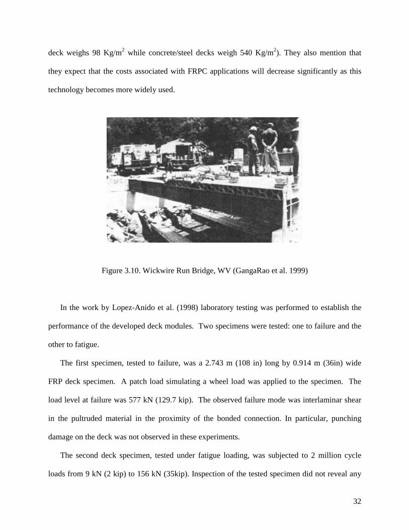
The Wickwire Run Bridge is located off US Route 119 in Taylor County, WV. The bridge is
9.14 m (30-ft) long by 6.60 m (21.7-ft) wide. Four longitudinal galvanized steel beams, spaced
1.83 m (6-ft) apart, support the modular FRP deck (Figure 3.10).
From the field tests, the authors have concluded that the performance of developed decks is
excellent, especially when they are used as a replacement for concrete decks. This is because
FRPC decks are much lighter than decks built using traditional materials (for example: FRPC
32
deck weighs 98 Kg/m2 while concrete/steel decks weigh 540 Kg/m2). They also mention that
they expect that the costs associated with FRPC applications will decrease significantly as this
technology becomes more widely used.
Figure 3.10. Wickwire Run Bridge, WV (GangaRao et al. 1999)
In the work by Lopez-Anido et al. (1998) laboratory testing was performed to establish the
performance of the developed deck modules. Two specimens were tested: one to failure and the
other to fatigue.
The first specimen, tested to failure, was a 2.743 m (108 in) long by 0.914 m (36in) wide
FRP deck specimen. A patch load simulating a wheel load was applied to the specimen. The
load level at failure was 577 kN (129.7 kip). The observed failure mode was interlaminar shear
in the pultruded material in the proximity of the bonded connection. In particular, punching
damage on the deck was not observed in these experiments.
The second deck specimen, tested under fatigue loading, was subjected to 2 million cycle
loads from 9 kN (2 kip) to 156 kN (35kip). Inspection of the tested specimen did not reveal any
33
crack propagation due to fatigue. After the application of the cyclic loads the FRP deck was
tested to failure. It was found that the failure load decreased only by about 4% when compared to
the specimen with no load history. However, the midspan deflection increased by about 10%.
It was found that developed FRP decks have a very high strength capacity than concrete
decks with only 20% of the weight. However, they are more flexible when compared to concrete
decks. Thus, in general, serviceability (deflection) requirements control the design of FRP
composite decks. This is because excessive deformation can cause premature deterioration of the
wearing surface as well as it can affect the performance of the fasteners.
In the work by GangaRao et al. (1999), both components and deck modules were tested in
the laboratory. Three-point static bending tests were conducted on both hexagonal and double-
trapezoid component specimens with three different spans: 60, 84, and 108 inches. Both a
20”x10” patch load, intended to simulate a wheel load of an AASHTO standard truck, and a strip
load using a 6-inch wide plate intended to cause the maximum bending strains, were applied to
the specimens. The deck module testing included static and fatigue bending tests on 3-ft long
simply supported deck modules. Only the patch load was used in the fatigue tests. For the
fatigue tests, a sinusoidal load ranging from 2 to 35 kips at a rate of 3 cycles per second was
applied at a maximum of 2 million cycles.
From the static bending tests, it was found that the flexural rigidity of an FRP composite
component is about one half of the flexural rigidity of an uncracked concrete component, and
about 3.7 times of the flexural rigidity of a cracked concrete component.
For the fatigue tests two FRP deck specimens were used. One was subjected to a prior load
history (two million fatigue cycles), while the other had no load history. From the results of the
static failure tests, it was found that both specimens experienced about the same maximum
34
deflection and failure load. Thus, the prior load history was found to have no significant effect on
the strength and stiffness of FRP deck. The authors conclude once again that FRP has an
excellent energy absorbing capability. The ultimate load capacity of the tested FRP composite
deck specimens exceeded the AASHTO-HS25 load by an excess of about 100 kips.
The failure mode of the double-trapezoid component was such that it failed at the junction of
web and flange at the applied load location. The failure mechanism consisted initially of web
buckling at the applied load location and propagated on both sides of the load patch. For the
double-trapezoid component, failure occurred at the web-flange junction. This was attributed to
the less than satisfactory fiber wet-out and high stress concentration zones near the re-entrant
angles of these specimens.
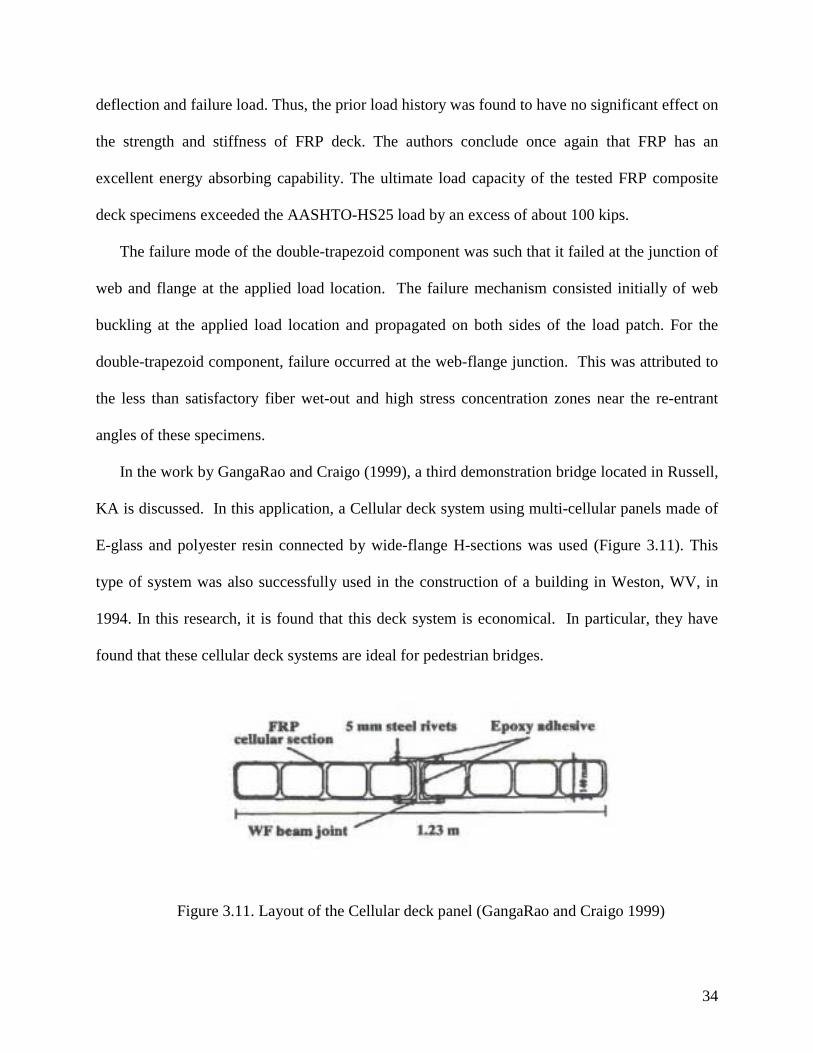
In the work by GangaRao and Craigo (1999), a third demonstration bridge located in Russell,
KA is discussed. In this application, a Cellular deck system using multi-cellular panels made of
E-glass and polyester resin connected by wide-flange H-sections was used (Figure 3.11). This
type of system was also successfully used in the construction of a building in Weston, WV, in
1994. In this research, it is found that this deck system is economical. In particular, they have
found that these cellular deck systems are ideal for pedestrian bridges.
Figure 3.11. Layout of the Cellular deck panel (GangaRao and Craigo 1999)
35
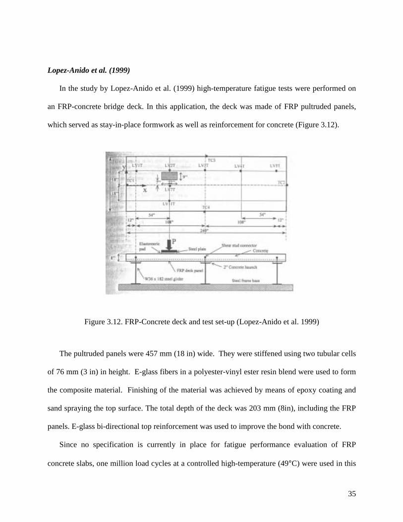
Lopez-Anido et al. (1999)
In the study by Lopez-Anido et al. (1999) high-temperature fatigue tests were performed on
an FRP-concrete bridge deck. In this application, the deck was made of FRP pultruded panels,
which served as stay-in-place formwork as well as reinforcement for concrete (Figure 3.12).
Figure 3.12. FRP-Concrete deck and test set-up (Lopez-Anido et al. 1999)
The pultruded panels were 457 mm (18 in) wide. They were stiffened using two tubular cells
of 76 mm (3 in) in height. E-glass fibers in a polyester-vinyl ester resin blend were used to form
the composite material. Finishing of the material was achieved by means of epoxy coating and
sand spraying the top surface. The total depth of the deck was 203 mm (8in), including the FRP
panels. E-glass bi-directional top reinforcement was used to improve the bond with concrete.
Since no specification is currently in place for fatigue performance evaluation of FRP
concrete slabs, one million load cycles at a controlled high-temperature (49°C) were used in this
36
work. More specifically, the FRP panel specimens were subjected to a maximum and minimum
fatigue load cycles of 92.5 kN and 8.9 kN, respectively, at a frequency of 4 Hz. The test
specimen consisted of a two-span continuously supported FRP-concrete deck panel with a girder
spacing of 2.74 m (108 in). The load was applied to simulate an AASHTO HS20-44 wheel load.
The main goal of the tests was to monitor the structural degradation during the fatigue tests,
since failure was not expected to occur during the applied load cycles. This is because
accumulation of damage due to cyclic loading is usually reflected in loss of stiffness of the FRP-
concrete deck material. Therefore, this work adopts the stiffness degradation as the fatigue
performance criterion for FRP-concrete decks. The main findings from the performed tests are:
• A 13% decrease in stiffness was observed for an increase in temperature from 19°C to 49°C.
• For high-temperatures, the stiffness decreased by approximately 5 to 6 % within the first
100,000 load cycles and remained almost unchanged after that and up to one million cycles.
Foster et al. (2000)
In the work by Foster et al. (2000), a 10-m-long by 7.3-m-wide (33x24 ft) GFRP composite
highway bridge installed in Butler County, Ohio is described. Both the support beams and the
deck were built using composite materials. In order to keep the cost of the application down, the
composite bridge components (deck and the support beams) were made of E-glass fibers in an
isopolyester resin matrix. Glass fibers cost about 10% less than carbon fibers (often used in the
aerospace industry) and isopolyester resins cost less than structural epoxy resin. This bridge,
referred to as “Tech 21”, was open to traffic in July 1997. Figure 3.13 shows the developed FRP
composite beam and Figure 3.14 (a) and (b) shows the assemblage of support beams.

37
Figure 3.13. FRP support beam (Foster et al. 2000)
In this application, asphalt was used for the wearing surface. Even though, the weight of the
asphalt layer was larger than that of the deck, the AASHTO HS-20 load requirement was
satisfied. It should be noted that most FRP bridge decks developed in the U.S. have adopted a
polymer concrete surface, since it is lighter in weight than asphalt. However, the authors justify
their choice by the fact that highway crews are more accustomed to using asphalt, especially for
resurfacing.
In this work, it is reported that the total installation time of the FRP composite bridge was
six weeks. The authors claim that the erection of an equivalent reinforced concrete bridge would
take ten weeks. In addition, the weight of the FRP bridge is 10.5 tons, while an equivalent RC
bridge would weigh 89 tons.

38
(a)
(b)
Figure 3.14. (a) Assembled FRP beams; (b) Underside view of the assembled FRP beams (Foster
et al. 2000)
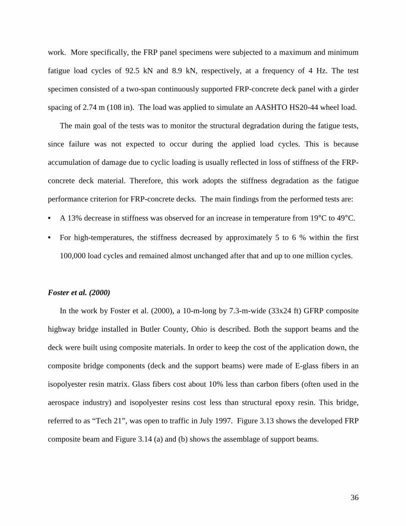
The bridge was subjected to live loads slightly lower than the required by AASHTO HS-20.
Figure 3.15 illustrates this test, where the loading was applied by means of two heavy-duty
trucks fully loaded with sand. The measurements were obtained with 28 steel strain transducers
39
externally installed for six different axle locations. The maximum load in the test series was a
static load of 64.6 metric tons (142,600 lb), which produced a maximum stress of 13.8 MPa
(2,000 lb/in2). In addition, the deflection curve obtained was comparable to that of a comparable
steel span.
Figure 3.15. Live load test of the “Tech 21” bridge (Foster et al. 2000)
The long-term performance of the FRP bridge is being monitored using the twenty fiber optic
sensors and 102 mechanical sensors that were embedded in the bridge. The authors of this work
expect that the findings from this research will be used in the development of the new AASHTO
composite bridge standards.
Hayes et al. (2000)
The work by Hayes et al. (2000) studies the feasibility of utilizing a composite bridge deck as
a replacement for deteriorated bridge decks or for new construction. More specifically, quasi-
static and fatigue were performed on a prototype composite bridge deck section. In these tests,

40
the flexural strength and stiffness were measured under a simulated wheel load. In addition, the
fatigue behavior and residual strength were assessed after fatigue loading, and failure modes
from fatigue and static loadings were determined.
Twelve pultruded 102x102x6.35-mm-thick square tubes sandwiched between two pultruded
9.53-mm-thick plates formed the studied deck section (Figure 3.16). The dimensions of the
specimen are 4.27-m in length, 1.22-m in width, and 121-mm in depth. The material of the plates
and tubes was formed by unidirectional and continuous strand mat glass fibers in an isophthalic
polyester resin. The tubes were connected using studs and nuts, and epoxy adhesive, while the
top plates were fastened using epoxy adhesive. The prototype deck panel did not include a
wearing surface, since it was assumed that such a surface would not significantly affect its
structural response.
Steel girders (W16x40) parallel to the short side of the deck were used to support the deck
(Figure 3.19 (a). The adopted girder spacing was 1.22-m, and the orientation of the square tubes
was transversal to the steel girders. The connection between the deck and the girders was
achieved with steel bolts, which passed through holes drilled through the deck and top flanges of
the steel beams. Flat steel washers were used to prevent the bolt head from bearing directly on
the top composite plate. A bearing pad was placed between the top flange of each W16x40 and
the deck. In order to provide transverse integrity under bearing load, wood block inserts were
place inside the fiberglass tubes at the hole locations.

41
(a)
(b)
Figure 3.16. The studied FRP deck: (a) Side view; (b) End view (Hayes et al. 2000)
The prototype deck panel was subjected to three types of tests. The first one was a static
service load test in the middle span of the deck; the second was a static loading to failure on the
left end; and the third was a fatigue performance and residual strength test (fatigue up to
3,000,000 cycles, followed by static loading to failure on the right end of the deck). A 508x305-
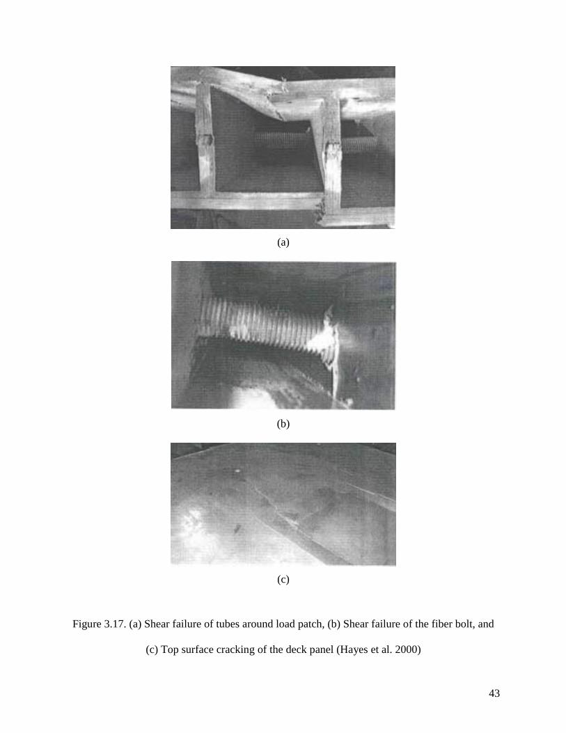
mm loading patch was used to simulate a wheel load on the top surface of the deck. Figure 3.17
shows the failure modes of the deck panel: (a) shear failure of tubes around load patch, (b) shear
failure of the fiber bolt, and (c) top surface cracking of the deck panel.

42
Failure of the deck occurred at 369 kN for deck in as-received condition and 369 kN for
decks subjected previously to fatigue strength test. These loads are about four times the design
wheel load, which is 92.6 kN. Therefore, the authors conclude that strength should not control
design. The midspan deflections of the deck panel under design wheel load were 3.81, 3.81, and
4.32 mm for the service load test, the as received test, and the post-fatigue strength test,
respectively.
It was found that even though the proposed deck system used off-the-shelf pultruded
sections, it met the necessary strength performance criteria. However, the deflections were
found to control the design when using the AASHTO criterion for limits of live load deflection
for steel, aluminum, and concrete construction. This criterion was used because no criterion is
available for FRP composite construction.
At the ultimate failure mode, shear failure of the top and bottom deck flanges were observed.
Even after 3,000,000 cycles of a fatigue load in excess of the design wheel load, no change in
stiffness or strength of the deck was observed. Finally, it was found that the connections between
deck and girder did not negatively impact the performance of the deck under static or fatigue
loading.
43
(a)
(b)
(c)
Figure 3.17. (a) Shear failure of tubes around load patch, (b) Shear failure of the fiber bolt, and
(c) Top surface cracking of the deck panel (Hayes et al. 2000)

44
Ohio DOT (2000)
The Ohio Department of Transportation spearheaded a study to evaluate different types
of FRP deck panels to replace a deteriorated reinforced concrete deck of a five-span continuous
haunched steel plate girder bridge. This demonstration project is known as the Salem Avenue
Bridge. This bridge carries six lanes of traffic and consists of twin structures with a longitudinal
joint and a 4-ft raised concrete median at the center. The girder spacing is approximately 8 feet 9
inches.
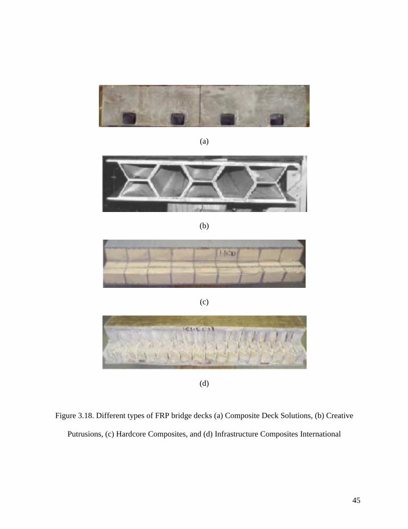
The deck of the north bridge structure was replaced by four different types of FRP deck
systems manufactured by the following four manufacturers: Creative Pultrusions (CP),
Composite Deck Solutions (CDS), Hardcore Composites (HC), and Infrastructure Composites
International (ICI) in collaboration with Kansas Structural Composites (KSCI). The CDS system
(Figure 3.18(a)) is the most similar to conventional reinforced concrete decks. This system uses
FRP stay-in-place forms to support the concrete deck and serve as bottom reinforcement, and
GFRP bars for the top reinforcement. The CP deck system is formed by bonding interlocking
pultruded FRP tubes that are installed in the direction perpendicular to the girders (Figure
3.18(b)). The HC and the ICI deck systems are similar. Both of these panels consist of a
lightweight FRP core sandwiched by high strength FRP skins. In the HP system, the core
consists of foam blocks wrapped with fiber cloth (Figure 3.18(c)). The ICI panel’s core is made
of corrugated glass fiber reinforced sheets (Figure 3.18(d)). On all three FRP deck panels (CP,
HC, and ICI) a 3/8-inch-thick polymer wearing surface manufactured and installed by Poly-Carb,
Inc., was applied. Prior to the application of this wearing surface, the decks’ surfaces were
lightly sandblasted.
45
(a)
(b)
(c)
(d)
Figure 3.18. Different types of FRP bridge decks (a) Composite Deck Solutions, (b) Creative
Putrusions, (c) Hardcore Composites, and (d) Infrastructure Composites International
46
This demonstration application was evaluated by a third party evaluation team. This
team was charged with the identification of potential maintenance and serviceability problems in
the application. A number of potential problems were identified by the team:
• In both the HC and ICI deck panels, both delamination and debonding in panel skins were
detected visually and via nondestructive testing. The evaluation team recommended that this
issue be addressed by the manufacturers.
• Some of the CP, HP and ICI deck panels lift off the haunch as much as 1/16 in. Therefore,
the connections between girder and deck may be inappropriate. This problem was not
anticipated and therefore not used as a criterion by ODOT or the manufacturers. The
evaluation team recommended that manufacturers together with ODOT to devise uniform
bearing.
• The wearing surface cracked above the field joints of the CP, HP and ICI deck panels, which
indicates that these joints are not working properly. This indicates that the Poly-Carb’s
wearing surface was not flexible enough to allow for this movement. During the evaluation
team’s investigation, the cracks were repaired with FRP fabric reinforcement, which seem to
have solved the problem.
• Hairline cracking was observed on the surface of the CDS deck. The cover was 1/2 to 3/4
inch less than the recommended 2 inches. The concrete deck was sealed with high-
molecular-weight methcrylate (HMWM). However, the team recommended that future
designs consider the elastic modulus of the GFRP bars in the determination of the amount of
shrinkage.
• Joint between different deck systems did not work properly. This was caused because the
different decks had different stiffness. The displacement differentials measured ranged from
47
1/64 to 1/8 inch. The evaluation team recommended that diaphragms be developed to
provide support for these joints.
• Water intrusion was detected in the HCI panel and water retention was observed in the ICI
panel. Potential water entry points include: anchor holes, which were open for more than a
month, face plate removal from CPI panels, or holes drilled for screw attachment of conduits
within concrete sidewalk. Drilling of drain holes in the underside of the panels were
recommended by the evaluation team.
• While a fire occurred alongside the HCI deck panel, no obvious structural damage seems to
have occurred. The evaluation team recommended periodic inspection and monitoring.
3.3. FRP Deck Manufacturers
A number of composite deck panel manufacturers, which were originally dedicated to
other industries such as the automotive and aerospace industries, have been alternatively re-
focusing their scope to the civil engineering industry. As mentioned in Chapter 2, the
manufacturers that have participated in most of the developed field applications are members of
the Market Development Alliance of the FRP Composites Industry (MDA). Each FRP deck
manufacturer has a demonstrated system that is applicable to a target application. The
manufacturer members of MDA of FRP deck panels are provided in this Section.
3TEX, Inc (www.3tex.com)
This manufacturer is located in Cary, North Carolina. While 3TEX has been involved in
areas of application such as the automotive, defense, recreational, etc., it has recently begun to
manufacture low-profile composite bridge decks and pedestrian bridges (girder spacing ranging

48
from 2 to 3 ft). Their system, referred to as TYCOR, is composed by a foam core reinforced in
the Z-direction sandwiched by fiberglass fabric skins (Figure 3.19). This system is intended as a
competitor to conventional corrugated steel decks. This manufacturer has completed one
application in Montgomery County, Ohio, and is currently developing a second application
WPAFB, Ohio.
Figure 3.19. TYCOR bridge deck panels
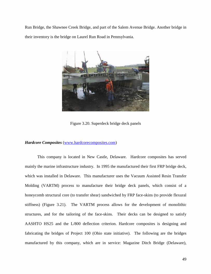
Creative Pultrusions, Inc. (www.pultrude.com or www.creativepultrusions.com) This manufacturer operates in two locations: Alum Bank, Pennsylvania and Roswell,
New Mexico. Their products are manufactured using the pultrusion process. Their bridge deck
panel, referred to as Superdeck, is formed the pultrusion and bonding of a double trapezoid and
a hexagonal section to form a bridge deck module (Figure 3.20). This deck is 20% lighter than
reinforced concrete, but the factor of safety is 6-to7 over the design load. These deck panels are
designed to comply with the AASHTO HS25 requirements. Among the applications developed
by this manufacturer are the following bridges in Ohio: the Laurel Lick Bridge, the Wickwire
49
Run Bridge, the Shawnee Creek Bridge, and part of the Salem Avenue Bridge. Another bridge in
their inventory is the bridge on Laurel Run Road in Pennsylvania.
Figure 3.20. Superdeck bridge deck panels
Hardcore Composites (www.hardcorecomposites.com)
This company is located in New Castle, Delaware. Hardcore composites has served
mainly the marine infrastructure industry. In 1995 the manufactured their first FRP bridge deck,
which was installed in Delaware. This manufacturer uses the Vacuum Assisted Resin Transfer
Molding (VARTM) process to manufacture their bridge deck panels, which consist of a
honeycomb structural core (to transfer shear) sandwiched by FRP face-skins (to provide flexural
stiffness) (Figure 3.21). The VARTM process allows for the development of monolithic
structures, and for the tailoring of the face-skins. Their decks can be designed to satisfy
AASHTO HS25 and the L/800 deflection criterion. Hardcore composites is designing and
fabricating the bridges of Project 100 (Ohio state initiative). The following are the bridges
manufactured by this company, which are in service: Magazine Ditch Bridge (Delaware),

50
Washington School House Road Bridge (Maryland), Muddy Run Bridge (Delaware), Bennett’s
Bridge (New York), Wilson’s Bridge (Pennsylvania), Greenbranch Trail Bridge (Delaware), Mill
Creek Bridge (Delaware), a bridge in Elmira (New York), and part of the Salem Avenue Bridge
(Ohio)
Figure 3.21. Hardcore’s bridge deck panels
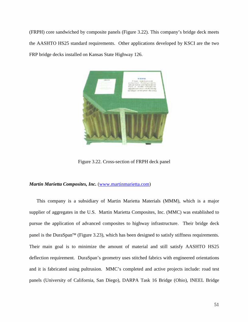
Kansas Structural Composites, Inc. (www.KSCI.com) This company was formed in 1995 and it is located in Russell, Kansas. The area of
concentration of KSCI, Inc. is the application of FRP bridge deck panels to deteriorating
highway infrastructure. Their first application in collaboration with Infrastructure Composites,
International (ICI) from San Diego, California, is the No-Name Creek Bridge in Kansas, was
developed in 1996. Their deck system consists of a fiber reinforced polymer honeycomb
51
(FRPH) core sandwiched by composite panels (Figure 3.22). This company’s bridge deck meets
the AASHTO HS25 standard requirements. Other applications developed by KSCI are the two
FRP bridge decks installed on Kansas State Highway 126.
Figure 3.22. Cross-section of FRPH deck panel
Martin Marietta Composites, Inc. (www.martinmarietta.com)
This company is a subsidiary of Martin Marietta Materials (MMM), which is a major
supplier of aggregates in the U.S. Martin Marietta Composites, Inc. (MMC) was established to
pursue the application of advanced composites to highway infrastructure. Their bridge deck
panel is the DuraSpan (Figure 3.23), which has been designed to satisfy stiffness requirements.
Their main goal is to minimize the amount of material and still satisfy AASHTO HS25
deflection requirement. DuraSpan’s geometry uses stitched fabrics with engineered orientations
and it is fabricated using pultrusion. MMC’s completed and active projects include: road test
panels (University of California, San Diego), DARPA Task 16 Bridge (Ohio), INEEL Bridge
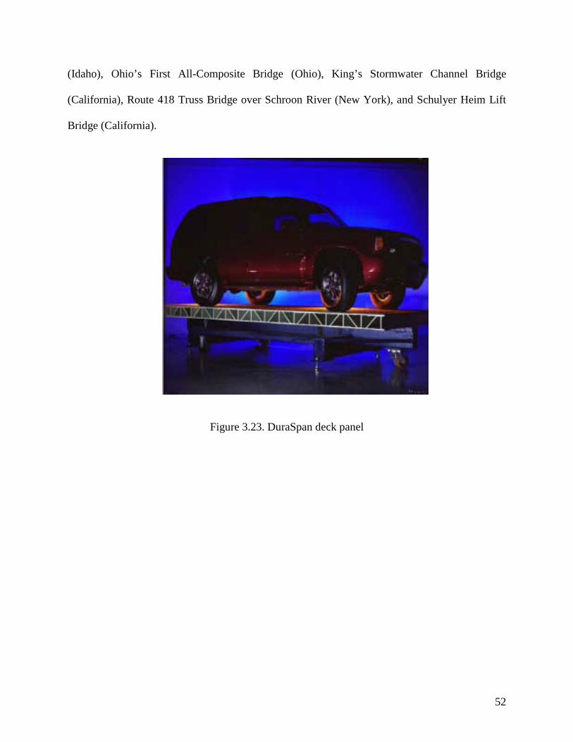
52
(Idaho), Ohio’s First All-Composite Bridge (Ohio), King’s Stormwater Channel Bridge
(California), Route 418 Truss Bridge over Schroon River (New York), and Schulyer Heim Lift
Bridge (California).
Figure 3.23. DuraSpan deck panel

53
Chapter 4. Survey of State DOTs
4.1 Introduction
A survey of state DOTs was conducted to investigate the use of FRP as a retrofit and as a
construction material for bridge decks. The main purpose of this survey was to collect as much
information as possible regarding the use of FRP in bridge decks in the United States. To achieve
this, two questionnaires were developed using the World Wide Web under the Purdue University
computer system. The Internet was used in order to expedite the process, as well as to increase
the number of potential respondents. The first questionnaire is a short one intended to screen the
DOTs with experience in using FRP in bridge decks. Only the state DOTs with this type of were
asked to respond the second more detailed questionnaire, which was intended to obtain specific
experiences by the DOTs who had used FRP for deck rehabilitation. The short and detailed
questionnaires are given in Appendices A and B, respectively.
The survey process consisted of first determining the appropriate contact person in each state
DOT. Each of these individuals was then sent e-mail explaining the purpose of survey, the
concept of the investigation, and the need for their responses. Moreover, a clear explanation of
how to access the survey’s website was provided in this e-mail. Informal follow-up email
messages were sent as a reminder to the non-respondent state DOT contact persons. The survey
responses have been summarized and are provided in tabular form in Section 4.2.
All fifty state DOTs were contacted. Of these, 34 responded the survey, i.e., a response ratio
of 64%. Of the 34 responding DOTs, 23 responded that they have used FRP for bridge desk
rehabilitation and/or installed FRP bridge decks. The major reasons provided by these states for
adopting FRP materials were their excellent strength, lightweight, and durability. Most of the

54
states using FRP as a material for bridge deck rehabilitation reported that its main use was to
strengthen and upgrade damaged bridge decks. Eight states responded that they had replaced a
reinforced concrete bridge deck by a FRP bridge deck. In their responses, these DOTs provided
information concerning their cost, construction time, and installation.
Of all the responding state DOTs, seven have had experience using FRP for deck
rehabilitation. Four of these state DOTs responded that utilized this material as external
strengthening for deficient decks and five of them responded that they applied the FRP retrofits
to the underside of deck. Based on their experience, these DOTs have not observed any problems
with their FRP application. The tables in the next section summarize the detailed information
obtained from the survey. This information include the methods and costs of pre-treatments,
types of FRP, costs, number of applied layers, types of adhesive, frequency and methods of
performance investigation, contractor’s information, design criteria, and repair techniques.
Twenty state DOTs have responded that they are considering using FRP in the future. Most
of them plan to utilize FRP as a strengthening/upgrading system. The majority of the responding
state DOTs stated that they would prefer using CFRP and adhesive epoxy.
4.2 Summary of State DOTs Responses
4.2.1 General
The questions in this section were intended to gage how widespread is the use of FRP in
bridge decks by state DOTs. Therefore, the responses encompass both the use of FRP as
a retrofit or as a construction material for bridge decks.

55
1. States in which bridge decks have been rehabilitated using FRP or in which FRP bridge
decks have been installed.
State DOT�
CA��CO��FL��GA��HI��IA��KS��MN��MO��NY��OH��OR��PA��TX��UT�
2. Reasons that lead states to adopt FRP materials
State DOT� Reasons for using FRP�
CA� Strength, lightweight, and ease of handling�CO� Investigating use of FRP�FL� non-corrosive�IA� The use of FRP materials in the strengthening/repaired schemes seems to be a
reasonable and cost effective alternative. This project was performed under the IBRC program.�
KS� Dead load reduction/durability�MO� Ease of application, potential % increase in slab strength�NY� Durability, Light weight, rapid construction�OH� Strength; light weight, durability�OR� Light weight�PA� Experimental reasons�TX� Funding and promotion thru the Federal, TEA-21, "Innovative Bridge Research and
Construction Program”�UT� Deterioration & Corrosion repairs. Steel fiber added to give tensile strength�

56
3. Reasons for rehabilitation
State DOT�
Reasons for rehabilitation:
corrosion�
Reason for rehabilitation: over-loading�
Reason for rehabilitation:
cracks�
Reason for rehabilitation:
strengthening/upgrade
Reason of rehabilitation: other�
CA� No� No� Yes� Yes��
CO� No� No� No� No� FRP reinforcing and pre-stressing in pre-cast SIP panels�
FL� Yes� Yes� Yes� Yes� Impact damage�GA� No� Yes� Yes� Yes�
�
IA� No� No� No� Yes��
KS� No� No� No� No� New Bridge: Rail/widening�
MO� No� No� No� Yes��
NY� Yes� No� No� Yes��
OH� No� No� Yes� Yes��
OR� No� No� No� Yes� Interest in new technology�
PA� No� Yes� No� Yes��
TX� Yes� No� No� No� Replacement, not rehab, of a deficient structure�
UT� Yes� No� Yes� No��

57
4.2.2 FRP Bridge Decks
In this section a summary of the survey responses concerning FRP bridge decks is provided.
1. States that have replaced a whole bridge deck by a FRP deck
State DOT� Replaced by a FRP deck: the whole bridge�
Replaced by a FRP deck: whole bridge deck and parts of the bridge
5) Replaced by a FRP deck: others�
IA� Yes� No��
KS� Yes� No��
NY� Yes� No��
OH� No� Yes��
OR� No� No� Bascule lift sections only�PA� Yes� No�
�
TX� No� No� New FRP-bar reinforced deck for replacement bridge
UT� Yes� No��
4. The approximate cost of the FRP composite bridge deck compared to the cost of a traditional
reinforced concrete bridge deck
State DOT� 6) Cost of the whole FRP deck� 7) Cost of concrete and reinforcement�CA� $130/SF� $65-$90/SF�
IA� $189,495� $110,220�KS� $67/SF� $22/SF�NY� $65-$100 / SF� $20-$25/SF�OH� $65/SF� $20/SF�

58
5. Number of days for the FRP composite deck to be installed; number of days for the same size
job if a reinforce concrete deck was installed instead; problems observed in these
applications.
State DOT�
Days for FRP desk
installation�
Days for concrete desk installation� Problems�
KS� 1� 28� Deck hold down hardware, joints leak�NY� 1-3� 45� Wearing surface failure, Some delamination�OH�
� �
Long time, various problems, performance problems: delamination, overlay cracking, haunch and connection details�
PA� 2-3� 15-20� Wearing surface, deck geometry, barrier connection�
UT� 14�� �
6. Opinions about the installation of FRP bridge decks.
State DOT�
FRP desk installation: very
easy�
FRP desk installation: fairly easy�
FRP desk installation: difficult�
FRP desk installation: other�
CA� No� No� No� N/A�IA� No� Yes� No�
�
KS� No� Yes� No��
NY� No� Yes� No��
OR� No� No� No� Unknown at this time�PA� No� Yes� No�
�
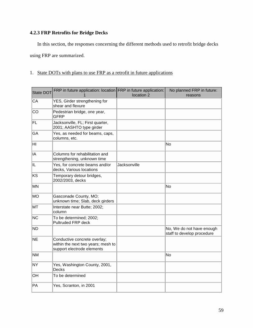
59
4.2.3 FRP Retrofits for Bridge Decks
In this section, the responses concerning the different methods used to retrofit bridge decks
using FRP are summarized.
1. State DOTs with plans to use FRP as a retrofit in future applications
State DOT�FRP in future application: location 1�
FRP in future application: location 2�
No planned FRP in future: reasons�
CA� YES, Girder strengthening for shear and flexure� � �
CO� Pedestrian bridge, one year, GFRP� � �
FL� Jacksonville, FL; First quarter, 2001; AASHTO type girder� � �
GA� Yes, as needed for beams, caps, columns, etc.� � �
HI�� �
No�
IA� Columns for rehabilitation and strengthening, unknown time� � �
IL� Yes, for concrete beams and/or decks, Various locations�
Jacksonville��
KS� Temporary detour bridges, 2002/2003, decks� � �
MN�� �
No�
MO� Gasconade County, MO; unknown time; Slab, deck girders� � �
MT� Interstate near Butte; 2002; column� � �
NC� To be determined; 2002; Pultruded FRP deck� � �
ND�� �
No, We do not have enough staff to develop procedure�
NE� Conductive concrete overlay; within the next two years; mesh to support electrode elements�
� �
NM�
� �
No�
NY� Yes, Washington County, 2001, Decks� � �
OH� To be determined�� �
PA� Yes, Scranton, in 2001�� �
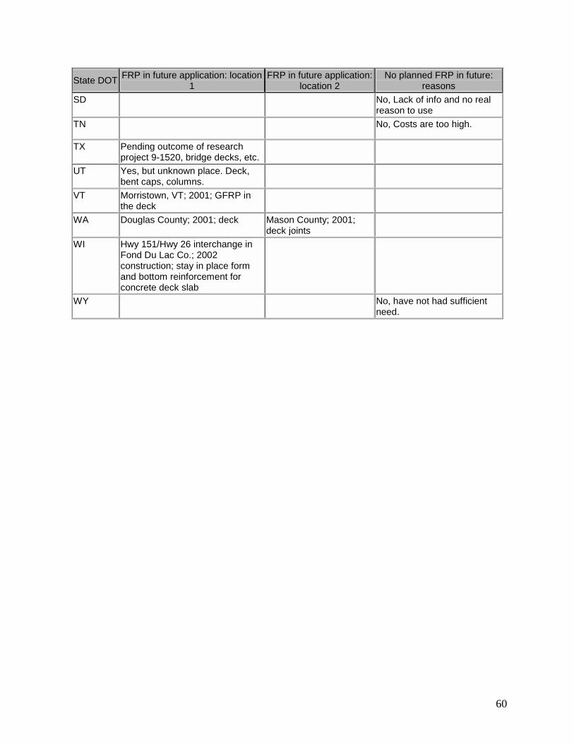
60
State DOT�FRP in future application: location 1�
FRP in future application: location 2�
No planned FRP in future: reasons�
SD�� �
No, Lack of info and no real reason to use�
TN�� �
No, Costs are too high.�
TX� Pending outcome of research project 9-1520, bridge decks, etc. � �
UT� Yes, but unknown place. Deck, bent caps, columns.� � �
VT� Morristown, VT; 2001; GFRP in the deck� � �
WA� Douglas County; 2001; deck� Mason County; 2001; deck joints� �
WI� Hwy 151/Hwy 26 interchange in Fond Du Lac Co.; 2002 construction; stay in place form and bottom reinforcement for concrete deck slab�
� �
WY�� �
No, have not had sufficient need.�
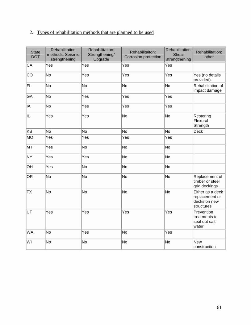
61
2. Types of rehabilitation methods that are planned to be used
State DOT�
Rehabilitation methods: Seismic
strengthening�
Rehabilitation: Strengthening/
Upgrade�
Rehabilitaiton: Corrosion protection�
Rehabilitation: Shear
strengthening�
Rehabilitation: other�
CA� Yes� Yes� Yes� Yes��
CO� No� Yes� Yes� Yes� Yes (no details provided).�
FL� No� No� No� No� Rehabilitation of impact damage�
GA� No� Yes� Yes� Yes��
IA� No� Yes� Yes� Yes��
IL� Yes� Yes� No� No� Restoring Flexural Strength�
KS� No� No� No� No� Deck�MO� Yes� Yes� Yes� Yes�
�
MT� Yes� No� No� No��
NY� Yes� Yes� No� No��
OH� Yes� No� No� No��
OR� No� No� No� No� Replacement of timber or steel grid deckings�
TX� No� No� No� No� Either as a deck replacement or decks on new structures�
UT� Yes� Yes� Yes� Yes� Prevention treatments to seal out salt water�
WA� No� Yes� No� Yes��
WI� No� No� No� No� New construction�

62
3. Types of FRP that are planned to be used
State DOT�
Type of FRP to be used: CFRP�
Type of FRP to be used: GFRP�
Type of FRP to be used: AFRP� Type of FRP to be used: other�
CA� Yes� No� No��
CO� No� No� No� N/A�FL� Yes� No� No�
�
GA� Yes� No� No��
IA� No� Yes� No� CFRPs have been used for repair of damage beams�
IL� Yes� No� No��
KS� No� Yes� No��
MO� Yes� No� No��
MT� Yes� No� No��
NE� No� No� No� Not determine yet�NY� Yes� Yes� No�
�
OH� No� Yes� No��
OR� No� Yes� No��
TX� No� No� No� Pending outcome of Research Project 9-1520�
UT� Yes� No� No��
VT� No� Yes� No��
WA� No� No� No� Unknown at this time�WI� No� No� No� Not yet known�

63
4. Types of adhesives that are planned to be used
State DOT� Type of adhesives�
CA� Epoxy�CO� N/A�FL� Amine type epoxy�GA� Resin�IL� 2-part Epoxy�KS� Polyester resin�MO� Unknown�MT� ??�TX� N/A�UT� Polymer epoxies with broadcast agg.�WI� N/A�
5. Contractors names
State DOT�
��
� Contractor���
�
FL� State of FL DOT�KS� Kansas Structure Composites�MO� Unknown�MT� None yet�TX� N/A�WI� Unknown at this time�
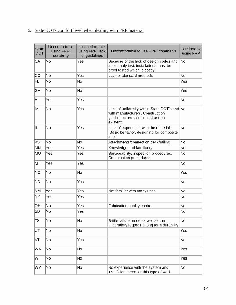
64
6. State DOTs comfort level when dealing with FRP material
State DOT�
Uncomfortable using FRP: durability�
Uncomfortable using FRP: lack
of guidelines�Uncomfortable to use FRP: comments� Comfortable
using FRP
CA� No� Yes� Because of the lack of design codes and acceptably test, installations must be proof tested which is costly.�
No�
CO� No� Yes� Lack of standard methods� No�FL� No� No�
�
Yes�
GA� No� No��
Yes�
HI� Yes� Yes��
No�
IA� No� Yes� Lack of uniformity within State DOT's and with manufacturers. Construction guidelines are also limited or non-existent.�
No�
IL� No� Yes� Lack of experience with the material. (Basic behavior, designing for composite action�
No�
KS� No� No� Attachments/connection deck/railing� No�MN� Yes� Yes� Knowledge and familiarity� No�MO� Yes� Yes� Serviceability, inspection procedures.
Construction procedures�No�
MT� Yes� Yes��
No�
NC� No� No��
Yes�
ND� No� Yes��
No�
NM� Yes� Yes� Not familiar with many uses� No�NY� Yes� Yes�
�
No�
OH� No� Yes� Fabrication quality control� No�SD� No� Yes�
�
No�
TX� No� No� Brittle failure mode as well as the uncertainty regarding long term durability�
No�
UT� No� No��
Yes�
VT� No� Yes��
No�
WA� No� No��
Yes�
WI� No� No��
Yes�
WY� No� No� No experience with the system and insufficient need for this type of work�
No�

65
7. Experience of retrofitting bridge decks with FRP & reasons for choosing FRP
State DOT�
FRP used on deck: external strengthening�
FRP used on deck: internal strengthening� FRP used on deck: other�
CA� Yes� No� Complete deck section using pultruded tubes and face sheets�
GA� Yes� No��
FL� Yes� No��
OH� Yes� No� Rebar, deck panels, piles, post tensioning�
OR� No� No� Pultruded deck section�TX� No� Yes� FRP-bars as internal reinforcement for
concrete�
8. Deck location where FRP retrofit was applied
State DOT� FRP applied to deck: underside�
FRP applied to deck: within the overlay� FRP applied to deck: others�
CA� Yes� No� GA� Yes� No� FL� Yes� No� MO� Yes� No� OH� Yes� No� OR� No� No� The body of the deck�TX� No� No� Top mat of deck reinforcement
(transversal & longitudinal)�
9. Problems encountered on FRP retrofitted bridge decks
State DOT� Problems�CA� No. FRP strips have been applied on deck less than a year ago�GA� No!�FL� Not in any of the slab applications�MO� Not to date�OH� No debonding in the field. Debonding occurred in lab testing�OR� Presently these decks have not been installed, we are in the contracting processTX� No!�

66
10. Pre-treatment process utilized on retrofitted bridge decks
State DOT� Pretreatment process�CA� No�GA� Sandblasting, some patching�FL� Surface cleaning by sand-blasting�MO� Bottom surface ground smooth with hand grinders; surface then lightly sand-blasted
to remove loose material and laitance�OH� Cleaning and patching bad concrete�OR� No�TX� No�
11. Cost of pre-treatment for FRP retrofits
State DOT�
��
� Cost for pretreatment: 1���
� Cost for pretreatment: 2���
� Cost for pretreatment: 3��
CA� N/A� N/A� N/A�GA� N/A�
� �
FL� ?�� �
MO� Hand grinding; cost unknown Sand blasting; cost unknown�
OH� Cleaning and patching; cost?� �
12. Cost of FRP retrofit without pre-treatment
State DOT�
��
� Unit price:$/per foot/per layer(no pretreatment)���
�
OR� $80.00�TX� $6.41�
13. Total cost of FRP retrofit on bridge decks
State DOT� FRP material Installation� Adhesive� TOTAL�TX� $45,137.00� $715.00�
�
$45,852.00�
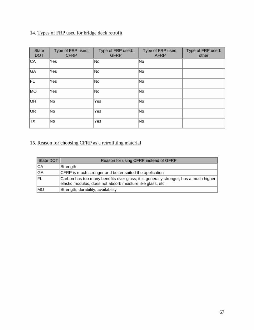
67
14. Types of FRP used for bridge deck retrofit
State DOT�
Type of FRP used: CFRP�
Type of FRP used: GFRP�
Type of FRP used: AFRP�
Type of FRP used: other�
CA� Yes� No� No��
GA� Yes� No� No��
FL� Yes� No� No��
MO� Yes� No� No��
OH� No� Yes� No��
OR� No� Yes� No��
TX� No� Yes� No��
15. Reason for choosing CFRP as a retrofitting material
State DOT� Reason for using CFRP instead of GFRP�CA� Strength�GA� CFRP is much stronger and better suited the application�FL� Carbon has too many benefits over glass, it is generally stronger, has a much higher
elastic modulus, does not absorb moisture like glass, etc.�MO� Strength, durability, availability�

68
16. Number of layers used on the bridge deck retrofit
State DOT� Layers applied: #� Layers applied: varied layers� Layers applied: other�CA� 1� No�
�
GA� 2� No��
FL��
Yes��
MO� 1� No��
OH��
Yes��
OR��
No� Pultruded section�
TX� 0� No� Transverse and longitudinal bars
17. Types of adhesive used on the bridge deck retrofit
State DOT� Types of adhesives used�
CA� SIKA epoxy�GA� Resin�FL� Amine type epoxy resin�MO� Two parts epoxy primer, epoxy putty, saturate�OR� N/A�TX� N/A�

69
18. Performance investigation of the bridge deck retrofit
State DOT�
Check FRP performance: once a
year�
Check FRP performance: twice a
year�
Check FRP performance: once every two years�
Check FRP performance: other�
CA� No� No� Yes��
GA� No� No� Yes��
FL� Yes� No� No��
MO� No� No� Yes��
OH� Yes� No� No��
OR� No� No� No� Once a year under research�
TX� No� No� No� Ongoing research monitoring thru August 2002�
19. Methods of performance investigation of bridge deck retrofits
State DOT�
Means of checking performance: sensor�
Means of checking performance: type of sensor�
Means of checking performance: other�
CA� No��
Visual�
GA� No��
Visual and by tapping�
FL� No��
Visual�
MO� No��
Visual inspection unless otherwise warranted�
OH� Yes��
Live load truck testing�
OR� Yes� Measured strain� Visual�TX� Yes� Undisclosed� Plan to load test�
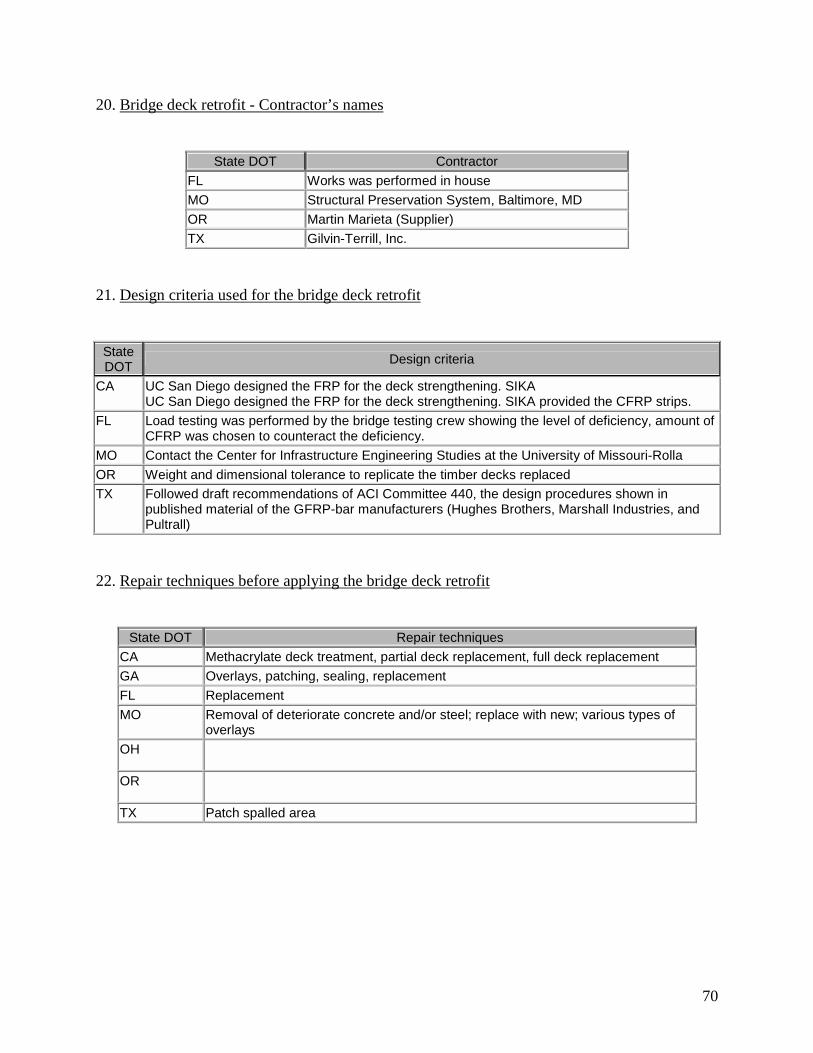
70
20. Bridge deck retrofit - Contractor’s names
State DOT� Contractor�
FL� Works was performed in house�MO� Structural Preservation System, Baltimore, MD�OR� Martin Marieta (Supplier)�TX� Gilvin-Terrill, Inc.�
21. Design criteria used for the bridge deck retrofit
State DOT� Design criteria�
CA� UC San Diego designed the FRP for the deck strengthening. SIKA UC San Diego designed the FRP for the deck strengthening. SIKA provided the CFRP strips.�
FL� Load testing was performed by the bridge testing crew showing the level of deficiency, amount of CFRP was chosen to counteract the deficiency.�
MO� Contact the Center for Infrastructure Engineering Studies at the University of Missouri-Rolla�OR� Weight and dimensional tolerance to replicate the timber decks replaced�TX� Followed draft recommendations of ACI Committee 440, the design procedures shown in
published material of the GFRP-bar manufacturers (Hughes Brothers, Marshall Industries, and Pultrall)�
22. Repair techniques before applying the bridge deck retrofit
State DOT� Repair techniques�
CA� Methacrylate deck treatment, partial deck replacement, full deck replacement�GA� Overlays, patching, sealing, replacement�FL� Replacement�MO� Removal of deteriorate concrete and/or steel; replace with new; various types of
overlays�OH�
�
OR��
TX� Patch spalled area�
71
Chapter 5. Summary of Findings, Conclusions, and Recommendations
5.1. Summary
The primary objective of this synthesis study was to provide INDOT with the current state of
knowledge on the usage of FRP in bridge decks. Both FRP retrofits for deficient bridge decks as
well as FRP bridge decks have been investigated. This investigation was achieved by means of a
thorough literature review and a web-based survey of other state DOTs.
5.1.1. FRP Retrofits for Bridge Decks Summary
The results from the literature review indicate that by externally bonding FRP plates (or
sheets) and/or rods provide excellent retrofitting mechanisms to increase deck strength as well as
stiffness of aging or deteriorated structures. The reinforcing element materials are usually made
of carbon (graphite), glass, and aramid (Kevlar ) fibers both types of retrofitting systems. They
are imbedded in a resin matrix (e.g. epoxy resins) and they provide most of the tensile strength of
the composite just as steel does in reinforced concrete. FRPC is usually manufactured in a
continuously woven form with different lengths or directions in order to provide the best
performance for different applications. The advantages of this retrofitting method include
reduced labor costs, minimum shutdown time/cost and traffic disruption, and minimal
maintenance requirements.
As mentioned above, the main goal of these types of retrofitting systems are to increase the
strength and/or stiffness of deficient bridge decks. From the literature review, it was found that
the values of such an increase varied for the different field applications. For an application

72
developed in Japan, in which two layers of CFRP installed parallel and perpendicular to the
traffic direction on the soffit of the cantilevered wing slab of a bridge deck, a reported reduction
of 30 to 40% in tensile strain was achieved. For an application developed in Missouri in which
both FRP sheets and rods externally bonded to the underside of a bridge were studied, the
reported increase in moment capacity ranged from 17 to 27%. In this study, it was also found
that the developed FRP rod system provided slightly better benefits than that provided by FRP
sheets. In a field application developed in Canada, in which FRP sheets were used to
“internally” reinforce a bridge deck, a reported increase of 35% in the bending strength and a
20% increase of shear strength were achieved. Finally, in a second application developed in
Missouri, in which CFRP sheets were bonded to the underside of a bridge deck, it was found that
the deflections after the strengthening were 94% of the original deflections. However, for the
most deteriorated portions of the deck the deflections reduced to 77% of the original deflections.
In this work, it was also found that after over one year after the retrofit had been installed, the
performance was almost identical to that of the performance of the recently retrofitted deck.
5.1.2. FRP Bridge Decks
Much of the research carried out in the use of FRP in civil industry has focused mainly in the
use of these materials to retrofit existing deficient structural components such as columns and
beams. However, an exciting application involves the use of FRPC in the replacement of
deficient bridge decks. Some demonstration projects have been developed to assess this
technology. These projects range from small-scale pedestrian bridges to large-scale highway
bridges as well as from deck replacement to bridges made entirely of composite materials.
73
Most of the studies found in the literature report that their FRP applications are performing
very well. In fact, some of these applications are now 3 or 4 years old and continue to show
excellent performance. In all cases, it is reported that the installation time is significantly
reduced when compared to conventional reinforced concrete decks. The only reported problems
were those encountered in the Salem Bridge in Ohio. In this application, decks from different
manufacturers were adopted in different spans of the highway bridge. In this application, the
main problems seem to have been caused by the difference of flexibility of the different deck
panels. The joints between the different deck systems did not work properly.
Finally, in a laboratory study that investigated different types of FRP bridge deck systems, it
was found that in all cases the FRP deck specimens have much higher failure loads and
comparable initial stiffness than equivalent reinforced concrete specimens. In particular, they
concluded that “box” and “trapezoidal” configurations have significantly better energy
absorption capacity. For all the tested FRP deck configurations, they found that even when
substantial cracking and fracture had occurred, the decks continued to carry load, thus, no
catastrophic failure was observed.
5.1.3. Survey of State DOTs
The experience of other state DOTs in the use of FRP as a retrofit and as a construction
material for bridge decks was investigated by means of a web-based survey. Two questionnaires
were developed. The first questionnaire was short and it was intended to screen the DOTs with
experience in using FRP in bridge decks. Only the state DOTs with this type of experience were
asked to respond the second more detailed questionnaire, which was intended to obtain specific
experiences by the DOTs who had used FRP for deck rehabilitation.

74
All fifty state DOTs were contacted. Of these, 34 responded the survey, i.e., a response ratio
of 64%. Of the 34 responding DOTs, 23 responded that they have used FRP for bridge desk
rehabilitation and/or installed FRP bridge decks. The major reasons provided by these states for
adopting FRP materials were their excellent strength, lightweight, and durability. Most of the
states using FRP as a material for bridge deck rehabilitation reported that its main use was to
strengthen and upgrade damaged bridge decks. Eight states responded that they had replaced a
reinforced concrete bridge deck by a FRP bridge deck.
Of all the responding state DOTs, seven have had experience using FRP for deck
rehabilitation. Four of these state DOTs responded that utilized this material as external
strengthening for deficient decks and five of them responded that they applied the FRP retrofits
to the underside of deck. Based on their experience, these DOTs have not observed any problems
with their FRP application.
Twenty state DOTs have responded that they are considering using FRP in the future. Most
of them plan to utilize FRP as a strengthening/upgrading system. The majority of the responding
state DOTs stated that they would prefer using CFRP and adhesive epoxy.
5.2. Conclusions
The results from the literature review and DOT survey indicate that FRP materials have been
successfully used in civil infrastructure applications, and in particular for bridge deck
strengthening and replacement. It also appears, from the results of this study that the use of FRP
in bridges is likely to continue and potentially become a mainstream material in the near future.
Their main advantages over conventional civil engineering materials, such as steel and concrete,
are their lightweight, corrosion and chemical resistance, and high strength.

75
5.3. Recommendations
The current state of knowledge of FRP materials as a construction material for civil
infrastructure indicates that it can be successfully used in many types of applications. The
present study focused in their use for bridge decks. In order to further benefit from this
technology, Indiana must become part of the increasing research efforts in this area. Therefore,
it is strongly recommended that a demonstration project be developed in this state. With this in
mind, a proposal has been developed and submitted to the FHWA Innovative Bridge Research
and Construction (IBRC) program, which is provided in Appendix C. In this project, the three
main spans of a bridge deck in Tippecanoe County will be replaced by 8” FRP deck panels. The
scope of this project includes the evaluation and design of FRP bridge deck panels to meet
current code requirements. It also involves the reconstruction of an existing bridge deck using
the innovative FRP deck panels. The monitoring of the performance of the developed
application will also be part of the proposed IBRC project. In case this IBRC proposal is not
successful, it is recommended that INDOT support such a research project.
76
List of References
1. Alkhrdaji, T., Nanni, A., Chen, G., and Barker, M., “Solid RC Decks Strengthened with
FRP,” Concrete International, October 1999, 37-41.
2. Arockiasamy, M, Amer, A. and Shahawy, M. A., “Concrete beams and slabs retrofitted
with CFRP laminates, ”Proceedings of Engineering Mechanics, ASEC, 2, 1996, 776-779.
3. Chajes, M., Gillespie, J., Mertz, D., and Shenton, H., “Advanced composite bridges in
Delaware,” Second International Conference on Composites in Infrastructure, ICCI’98,
1998, 645-650.
4. Emmons, P. H., Vaysburd, A. M., and Thomas, J., “Strengthening concrete structures, Part
II,” Concrete International, 20(3), 1998, 56-60.
5. Foster, D. C., Richards, D., and Bogner, B. R., “Design and installation of fiber-reinforced
polymer composite bridge,” Journal of Composites for Construction, ASCE, 4(1), 2000, 33-
37.
6. GangaRao, H. V. S., and Craigo, C., “Fiber-reinforced composite bridge desks in the USA,”
Structural Engineering International, IABSE, 9(2), 1999, 286-288.
7. GangaRao, H. V. S., Thippeswamy, H. K., Shekar, V., and Craigo, C., “Development of
glass fiber reinforced polymer composite bridge desk,” SAMPE Journal, 35(4), 1999, 12-
24.

77
8. Hayes, M. D., Ohanehi, D., Lesko, J. J., Cousins, T. E., and Witcher, D., “Performance of
tube and plate fiberglass composite bridge deck,” Journal of Composites for Construction,
ASCE, 4(2), May 2000, 48-55.
9. Hoa, S. V., Xie, M., and Xiao, X. R., “Repair of steel reinforced concrete with
carbon/epoxy composites,” Advanced Composite Materials in bridges and Structures,
Canadian society for Civil Engineering, 1996, 573-580.
10. Johansen, G. E., Wilson, R. J., Roll, F., Gaudini, G., “Design and construction of long span
FRP pedestrian bridges,” Building to Last Structures Congress – Proceedings, ASCE, New
York, 1, 1997, 46-50.
11. Karbhari, V. M., Seible, F., Hegemier G. A., and Zhao, L., “ Fiber reinforced composite
decks for infrastructure renewal-results and issues,” Marketing/technical/regulatory
Sessions of the Composites Institute’s Iinternational Composites Expo, Composites Institute
of the Society of the Plastics Industry, New York, 1997, 3C/1-3C/6.
12. Lopez-Anido, R., Dutta, P., Bouzon, J., Morton, S., Shahrooz, B., and Harik, I.,” Fatigue
evaluation of FRP-concrete bridge deck on steel girders at high temperature,” 44th
International SAMPE Symposium, 44(II), 1999, 1666-1675.
13. Lopez-Anido, R., GangaRao, H. V. S., Troutman, D., and Williams, D., “Design and
construction of short-span bridges with modular FRP composite deck,” Second
International Conference on Composites in Infrastructure, ICCI’98, 1998, 705-714.
14. Mayo, R, Nanni, Antonio, Watkins, S., Barker, M., and Boothby, T., “Strengthening of
Bridge G270 with Externally Bonded Carbon Fiber Reinforced Polymer (CFRP),” Center

78
for Infrastructure Engineering Studies Report CIES 99-15, University of Missouri-Rolla,
Missouri, 1999.
15. MDA Product Selection Guide: FRP Composite Products for Bridge Applications, First
Edition, Ed. John P. Busel, Market Development Alliance of the FRP Composites Industry,
Harrison, NY 10528-1632, 2000.
16. Nanni, A., “Concrete repair with externally bonded FRP reinforcement,” Concrete
International, 17(6), 1995, 22-26.
17. Ohio Department of Transportation, Evaluation of Salem Avenue Bridge Deck
Replacement, Issues Regarding Composite Material Systems Used, Final Report MOT-49-
1.634, PID No. 17939, Ed. Mark P. Henderson, December 1, 2000.
18. Rizkalla, S. and Labossière, P., “Structural Engineering with FRP – in Canada,” Concrete
International, October 1999, 25-28.
19. Teng, M.H., Sotelino, E.D., and Chen, W.F. (2000). “Monitoring of Long-Term
Performance of Highway Bridge Columns Retrofitted by Advanced Composite Jackets in
Indiana,” INDOT Draft Report, SPR-2161.
20. Walker, H. S., “Fiberglass bridges and bridge decks,” Second International Conference on
Composites in Infrastructure, ICCI’98, 1998, 651-656.

79
APPENDICES
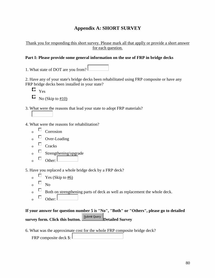
80
Appendix A: SHORT SURVEY
Thank you for responding this short survey. Please mark all that applly or provide a short answer
for each question. Part I: Please provide some general information on the use of FRP in bridge decks
1. What state of DOT are you from?
2. Have any of your state's bridge decks been rehabilitated using FRP composite or have any FRP bridge decks been installed in your state?
Yes
No (Skip to #10) 3. What were the reasons that lead your state to adopt FRP materials?
4. What were the reasons for rehabilitation?
o Corrosion
o Over-Loading
o Cracks
o Strengthening/upgrade
o Other: 5. Have you replaced a whole bridge deck by a FRP deck?
o Yes (Skip to #6)
o No
o Both on strengthening parts of deck as well as replacement the whole deck.
o Other: If your answer for question number 5 is "No", "Both" or "Others", please go to detailed
survey form. Click this button. Submit Query
Detailed Survey
6. What was the approximate cost for the whole FRP composite bridge deck?
FRP composite deck $:
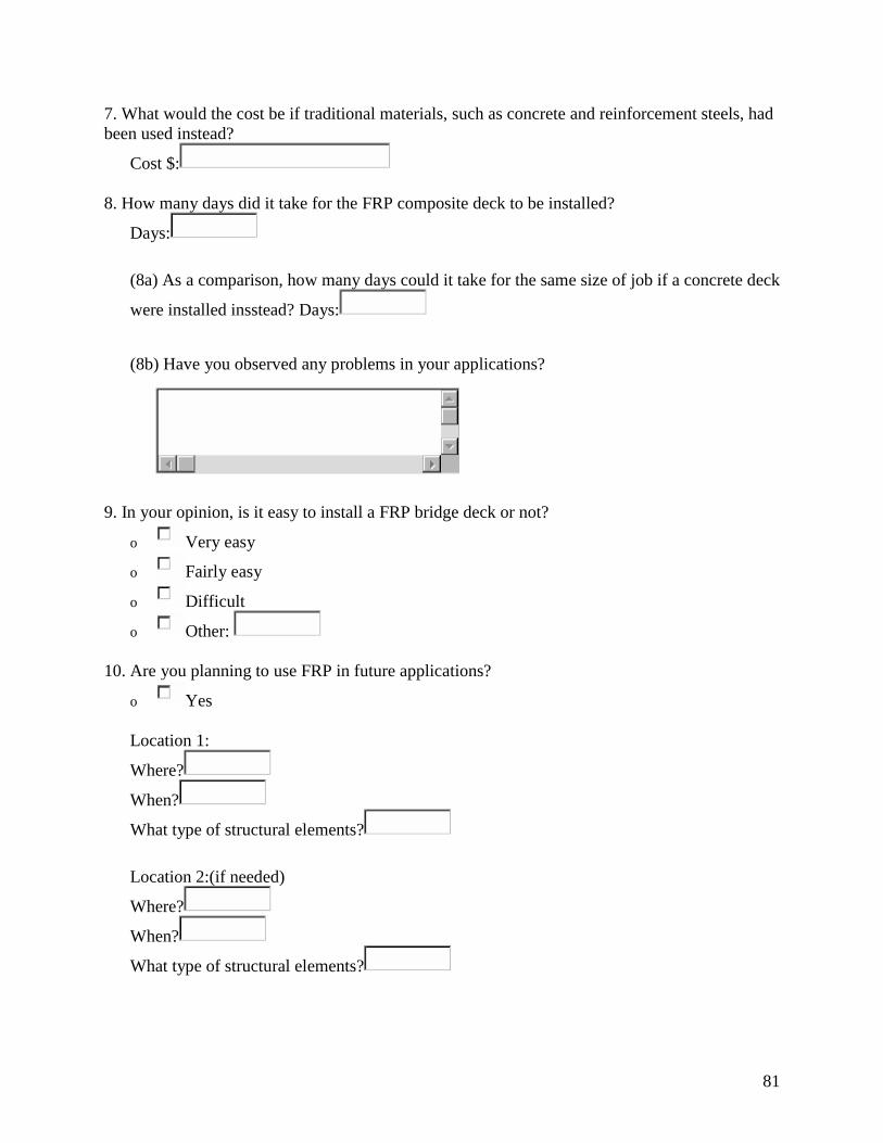
81
7. What would the cost be if traditional materials, such as concrete and reinforcement steels, had been used instead?
Cost $: 8. How many days did it take for the FRP composite deck to be installed?
Days:
(8a) As a comparison, how many days could it take for the same size of job if a concrete deck
were installed insstead? Days:
(8b) Have you observed any problems in your applications?
9. In your opinion, is it easy to install a FRP bridge deck or not?
o Very easy
o Fairly easy
o Difficult
o Other: 10. Are you planning to use FRP in future applications?
o Yes
Location 1:
Where?
When?
What type of structural elements? Location 2:(if needed)
Where?
When?
What type of structural elements?

82
o No. Please provide the reasons
(Skip to #15)
11. What types of rehabilitation methods will be used?
o Seismic Strengthening
o Strengthening/Upgrade
o Corrosion Protection
o Shear Strengthening
o Other: 12. What type of FRP will be used?
o CFRP (Carbon Fiber Reinforced Plastic)
o GFRP (Glass Fiber Reinforced Plastic)
o AFRP (Armid Fiber Reinforced Plastic)
o Other: 13. What types of adhesives will be used?
14. Please provide the name of the contractor if known?
15. What makes you feel uncomfortable when dealing with this kind of material (FRP)?
o Durability issue
o Lack of design guidelines
o Other:
o No, I feel comfortable while using it. Part II: Please provide your individual information
16. If you would, please provide a way for us to contact you in the future.
Name:
Tel:
Fax:
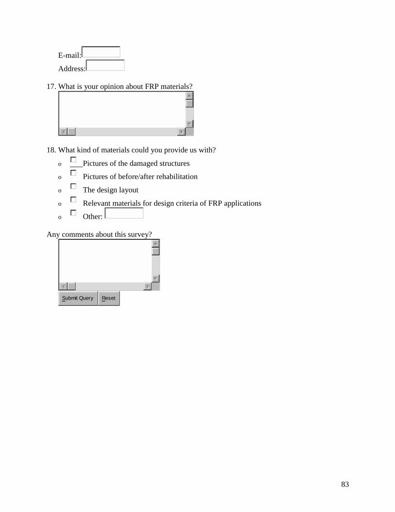
83
E-mail:
Address: 17. What is your opinion about FRP materials?
18. What kind of materials could you provide us with?
o Pictures of the damaged structures
o Pictures of before/after rehabilitation
o The design layout
o Relevant materials for design criteria of FRP applications
o Other: Any comments about this survey?
Submit Query Reset
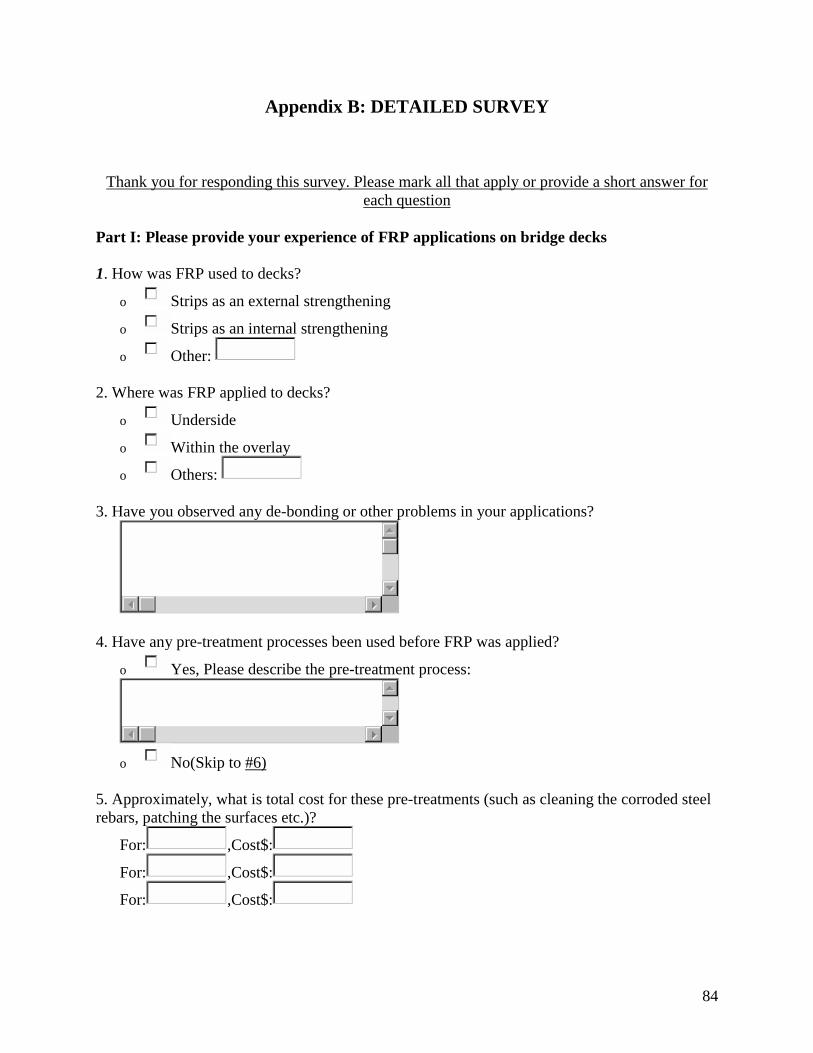
84
Appendix B: DETAILED SURVEY
Thank you for responding this survey. Please mark all that apply or provide a short answer for
each question Part I: Please provide your experience of FRP applications on bridge decks 1. How was FRP used to decks?
o Strips as an external strengthening
o Strips as an internal strengthening
o Other: 2. Where was FRP applied to decks?
o Underside
o Within the overlay
o Others: 3. Have you observed any de-bonding or other problems in your applications?
4. Have any pre-treatment processes been used before FRP was applied?
o Yes, Please describe the pre-treatment process:
o No(Skip to #6)
5. Approximately, what is total cost for these pre-treatments (such as cleaning the corroded steel rebars, patching the surfaces etc.)?
For: ,Cost$:
For: ,Cost$:
For: ,Cost$:
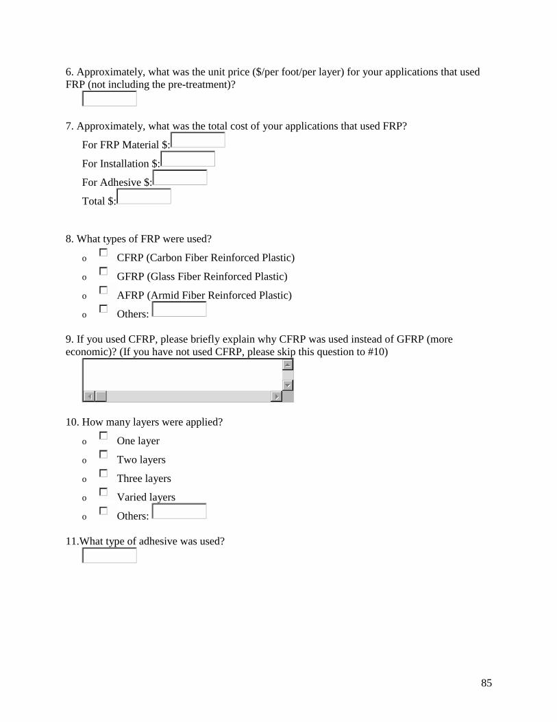
85
6. Approximately, what was the unit price ($/per foot/per layer) for your applications that used FRP (not including the pre-treatment)?
7. Approximately, what was the total cost of your applications that used FRP?
For FRP Material $:
For Installation $:
For Adhesive $:
Total $: 8. What types of FRP were used?
o CFRP (Carbon Fiber Reinforced Plastic)
o GFRP (Glass Fiber Reinforced Plastic)
o AFRP (Armid Fiber Reinforced Plastic)
o Others: 9. If you used CFRP, please briefly explain why CFRP was used instead of GFRP (more economic)? (If you have not used CFRP, please skip this question to #10)
10. How many layers were applied?
o One layer
o Two layers
o Three layers
o Varied layers
o Others: 11.What type of adhesive was used?

86
12.In bridge deck applications, how often do you check their performance?
o Once a year
o Twice a year
o Once every two Years
o Other:
o Never (Skip to #14) 13. How do you check the performance?
o By means of installed sensors. What kind of sensors?
o Other methods (Please specify): 14. Please provide the contractor information.
15. It will be greatly appreciated if you provide some relevant materials concerning the design criteria for your FRP applications.
o Yes, see attached.
o No, not this time.
o Other: 16. Please describe briefly the design criteria used in your FRP applications for decks. If you do not have this information, please direct us how to obtain it.
17. What repair techniques do you most commonly use for bridge decks?
*** If you have not replaced a whole bridge deck by a FRP deck, please skip to #22) *** 18. What is the approximate cost for the whole FRP composite bridge deck (please provide the dimensions of the deck)?
FRP composite deck $:
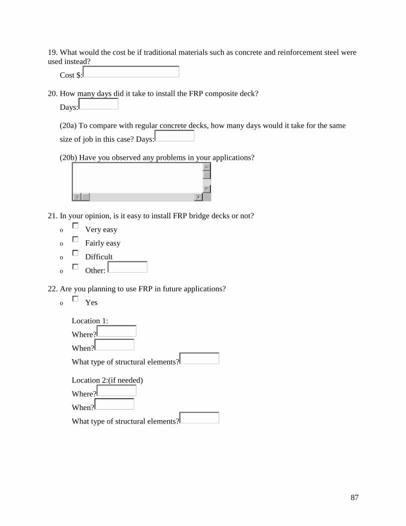
87
19. What would the cost be if traditional materials such as concrete and reinforcement steel were used instead?
Cost $: 20. How many days did it take to install the FRP composite deck?
Days:
(20a) To compare with regular concrete decks, how many days would it take for the same
size of job in this case? Days: (20b) Have you observed any problems in your applications?
21. In your opinion, is it easy to install FRP bridge decks or not?
o Very easy
o Fairly easy
o Difficult
o Other: 22. Are you planning to use FRP in future applications?
o Yes
Location 1:
Where?
When?
What type of structural elements?
Location 2:(if needed)
Where?
When?
What type of structural elements?
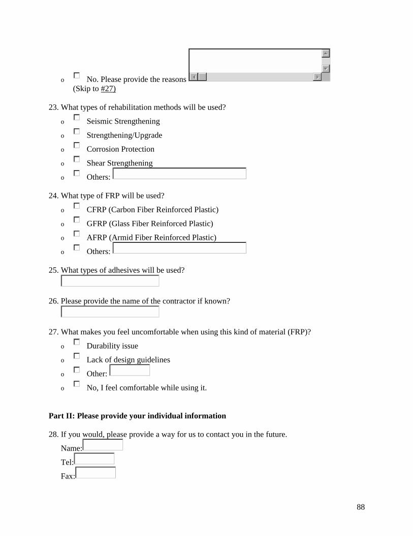
88
o No. Please provide the reasons
(Skip to #27)
23. What types of rehabilitation methods will be used?
o Seismic Strengthening
o Strengthening/Upgrade
o Corrosion Protection
o Shear Strengthening
o Others: 24. What type of FRP will be used?
o CFRP (Carbon Fiber Reinforced Plastic)
o GFRP (Glass Fiber Reinforced Plastic)
o AFRP (Armid Fiber Reinforced Plastic)
o Others: 25. What types of adhesives will be used?
26. Please provide the name of the contractor if known?
27. What makes you feel uncomfortable when using this kind of material (FRP)?
o Durability issue
o Lack of design guidelines
o Other:
o No, I feel comfortable while using it. Part II: Please provide your individual information 28. If you would, please provide a way for us to contact you in the future.
Name:
Tel:
Fax:

89
E-mail:
Address: 29. What is your opinion about FRP materials?
30. What kind of materials could you provide us with?
o Pictures of the damaged structures
o Pictures of before/after rehabilitation
o The design layout
o Relevant materials for design criteria of FRP applications
o Others: Any comments about this survey?
Submit Query Reset

90
Appendix C: IBRC proposal
APPLICATION for
TEA-21 INNOVATIVE BRIDGE CONSTRUCTION PROGRAM State: Indiana State’s Priority Ranking: # 1 of 1 Project type (new construction, replacement, rehabilitation or repair): rehabilitation NBI structure number: 7900092 County: Tippecanoe Structure Name and/or Identifying Description (e.g. Number/Name of Route on the Bridge and Feature Crossed): Bridge No. 138 on County Road 900E over the North fork of Wildcat Creek, 0.8 miles south of State Road 26. Structure Description (e.g., bridge type, number of spans, length, width, material): This bridge has 3 main spans and 2 concrete approaches. The main spans are 50’-0” – 60’-0” – 50’-0” and consist of a conventional concrete deck on steel girders. The approaches have a 24’-0” span and are built with concrete T-beams. The bridge is 24’-0” wide. Innovative Material (describe the material, how it is used and how the project meets one or more of the program goals):
Innovative Material Fiber-Reinforced Polymer (FRP) deck panels will be investigated as an alternative to conventional reinforced concrete (RC) decks. FRP deck panels have two components: a reinforcing element and a supporting matrix. The reinforcing elements are glass or carbon fibers, which typically have higher tensile strength than traditional reinforcing steel. The supporting matrix is commonly a thermosetting polymer resin (polyester, epoxy). A common configuration for FRP bridge deck panels consists of a lightweight FRP core sandwiched by high strength FRP skins. This lightweight high strength material exhibits superior corrosion resistance when compared to conventional reinforced concrete. Proposed Work In the proposed project, an existing deteriorating bridge deck in Tippecanoe County, Indiana will be replaced using advanced composite materials. The proposed work will build upon
91
research conducted in previous project funded by INDOT through Joint Transportation Highway Program (JTRP) entitled “Strengthening of Deteriorating Decks of Highway Bridges in Indiana Using FRPC.” In the previous work, a synthesis study was carried out to study the feasibility of using of FRP as a construction material for bridge decks in Indiana. The present study will implement the knowledge acquired in the previous research through the development of an application. More specifically, the deck of the three main spans of the target bridge will be replaced with 8” FRP decks. The scope of this project includes the evaluation and design of FRP bridge deck panels to meet current code requirements. It also involves the reconstruction of an existing bridge deck using the innovative FRP deck panels. The monitoring of the performance of the developed application will also be part of the proposed project. This project will add to the growing database of FRP deck applications and aid in the development of design guidelines. Successful application of FRP to the proposed test structure in combination with new design procedures and the acquired construction experience will allow for easy duplication to similar bridges in the state of Indiana. Program Goals The deterioration of concrete bridge decks in Indiana occurs mainly due to the corrosion of steel reinforcing bars. One of the solutions for new construction adopted in Indiana to curb this problem is to use epoxy-coated steel reinforcing bars and the increase of concrete cover to 2 ½ inches. So far, bridge decks built using this new style of construction have not experienced corrosion, but have started to exhibit widespread cracking. This is mostly due to increased traffic volumes or weights in excess of the original design values. Overlay is currently used to repair mildly damaged decks, while severely damaged decks are often replaced. Both of these techniques are expensive, time consuming, and cause severe traffic disruption. Advanced composites provide an excellent alternative as a construction material for bridge decks. This is because these materials offer significant advantages over conventional materials due to their chemical and corrosion resistance, lightweight, high strength, and low maintenance. The utilization of FRP as a construction material for bridge decks promises to reduce maintenance, construction time, and life cycle costs. While there are numerous suppliers and types of FRP decks currently available, there are not enough built test structures needed for the creation of more cohesive guidelines and procedures for implementation. In fact, each application requires detailed modeling and experimental verification prior to construction. An in-state test structure would allow Indiana to evaluate FRP bridge deck panels and help pave the way for approval of this innovative material as a regular material for recurring use in the state. Tippecanoe County is poised to take the lead in the design and implementation of FRP bridge deck systems in Indiana. The proposed project meets several of the IBRC program goals. ��Development of new, cost-effective innovative material highway bridge applications.
92
FRP has been utilized in a number of industries, such as aerospace, automotive, etc., for many years, but it is still new to civil engineering applications. This material has numerous advantages over traditional materials, such as concrete and steel. These improved properties affect the design, construction, and long-term performance of applications such as bridge decks. Due to their superior long-term performance, FRP bridge deck panels are low maintenance and will not require the recurring costs associated with rehabilitation and replacement, as is the case for conventional bridge decks. These and other benefits are described in more detail below. ��Reduction of maintenance costs and life cycle costs of bridges. Replacement of conventional reinforced concrete bridge decks with FRP decks will eliminate the recurring costs associated with repair and replacement related to corrosion. Furthermore, the relatively lighter FRP decks have the potential of increasing the lifespan of the supporting girders, piers, and foundations. ��Development of construction techniques to increase safety and reduce construction time and traffic congestion. Lightweight prefabricated FRP decks allow for quicker installation. Typically their installation can be achieved in a matter of days rather than weeks as for conventional reinforced concrete decks. The result is less traffic disruption and consequently a lower threat to public safety. Considering the reduced need for maintenance and repair, the traffic disruption is decreased even further. ��Development of engineering design criteria for innovative products and materials for use in highway bridges and structures. The proposed work will investigate FRP deck panel applications for a typical three-span bridge. The proposed test structure can provide the much needed field data for the development of design and construction procedures. A successful combination of design guidelines and the experience with this test structure will provide Indiana with information for future regular use of these innovative deck panels.
Schedule for start of work (month/year): Project to be let July 2002 Cost Estimates: Total project cost: P $755,000 Cost of “innovative material” portion of construction A $300,000 Preliminary engineering cost, if requested B $100,000 Cost of innovative material performance evaluation

93
(e.g., for a 2-year post-construction period) C $75,000 PE costs + construction costs + evaluations costs = (A+B+C) T $475,000 Total Federal Program Funds Requested…………………………. $$ $475,000
State Department of Transportation Contact Person
Name: Tommy Nantung Title: Section Manager; Pavement, Materials, and Accelerated Testing Agency: INDOT Ph: (765) 463-1521 ext. 248 Fax: (765) 497-1665 e-mail: [email protected] Local Agency Contact Person (if available)
Name: Mark Albers Title: Executive Director Agency: Tippecanoe County Highway Department Ph: (765) 423-9210 Fax: (765) 423-9127 e-mail: [email protected] FHWA Division Office Contact Person
Name: Keith Hoernschemeyer Title: Division Bridge Engineer Division Office: Indiana Ph: (317) 226-7490 Fax: (317) 226-7341 e-mail: [email protected] Purdue University Contact Persons Name: Elisa D. Sotelino Title: Associate Professor Department: School of Civil Engineering Ph: (765) 494-2228 Fax: (765) 496-1105 e-mail: [email protected] Name: Judy Liu
Title: Assistant Professor Department: School of Civil Engineering Ph: (765) 494-2254 Fax: (765) 496-1105 e-mail: [email protected]