strengthening of thin metallic cylindrical shells using ... · declaration this thesis entitled...
TRANSCRIPT
Strengthening of thin metallic
cylindrical shells using fibre reinforced
polymers
Thesis submitted in fulfilment of the requirements for the degree of
Doctor of Philosophy
By
Mustafa Batikha
Supervisors: Professor J. Michael Rotter
Dr. Jian-Fei Chen
Institute for Infrastructure & Environment
The School of Engineering and Electronics
The University of Edinburgh
William Rankine Building, The King's Buildings, Edinburgh, Scotland, UK
EH9 3JL
2008
Declaration
This thesis entitled “Strengthening of thin metallic cylindrical shells using fibre
reinforced polymers”, is submitted to the Institute for Infrastructure & Environment,
The School of Engineering and Electronics, The University of Edinburgh, William
Rankine Building, The King's Buildings, Edinburgh, EH9 3JL, for the Degree of
Doctor of Philosophy.
The research was solely the work of the author expect where otherwise
acknowledged in the text and has not formed the basis of a submission for any other
degree. Publications based on this thesis:
Batikha M , Chen JF and Rotter JM (2007). “FRP strengthening of metallic
cylindrical shells against elephant‘s foot buckling.” Proc. of the Conference on
Advanced Composites in Construction, ACIC 07, 2-4 April, Bath, UK, 157-164.
Batikha M , Chen JF and Rotter JM (2007). “Numerical modelling of shells repaired
using FRP.” Proc. of the 3rd International Conference on Steel and Composites
Structures, ICSCS 07, 30 July-1 August, Manchester, UK, 1065-1069.
Batikha M , Chen JF, Rotter JM (2007). “Elastic buckling of FRP-strengthened
cylinders with axisymmetric imperfections”. Proc., Asia-Pacific Conference on
FRP in Structures, APFIS 2007, 12-14 December, Hong Kong, 1011-1016.
Batikha M , Chen JF, Rotter JM (2008). “Strengthening metallic shells with FRP
against buckling”. Proc. of the 4th International Conference on FRP Composites
in Civil Engineering, CICE 2008, 22-24 July, Zurich, Switzerland, accepted.
Mustafa Batikha
Date
Abstract
Steel silos are widely used as long-term or short-term containers for the storage
of granular solids, of which a huge range are stored, from flour to iron ore pellets,
coals, cement, crushed rocks, plastic pellets, chemical materials, sand, and concrete
aggregates. The radius to thickness ratio for silos is in the range of 200 to 3000, so
they fall into the category of thin shells, for which failure by buckling is the main
concern and requires special attention in design. The primary aim of this thesis is to
investigate the possible application of Fibre Reinforced Polymer (FRP) as a new
repair and strengthening technique to increase the buckling capacity of thin metallic
cylindrical shells. Extensive research has been conducted on the use of fibre
reinforced polymer (FRP) composites to strengthen concrete, masonry and timber
structures as well as metallic beams. However, all these studies were concerned with
failure of the structure by material breakdown, rather than stability. As a result, this
thesis marks a major departure in the potential exploitation of FRP in civil
engineering structures.
Many analyses of cylindrical shells are presented in the thesis. These are all
focussed on strengthening the shell against different failure modes. Two loading
conditions were explored: uniform internal pressure accompanied by axial load near
a base boundary, and axial loads with geometric imperfections. For the latter, local
imperfections are usually critical, and two categories of imperfection were studied in
detail: an inward axisymmetric imperfection and a local dent imperfection.
For the first loading condition, which leads to elephant’s foot buckling, an
analytical method was used to derive general equations governing the linear elastic
behaviour of a cylindrical shell that has been strengthened with FRP subject to
internal pressure and axial compression. It was used to identify optimal application
of the FRP. All the later studies were conducted using nonlinear finite element
analysis (using the ABAQUS program) to obtain extensive predictions of many
conditions causing shell buckling and the strengthening effect of well-placed FRP.

In all the cases studied in this thesis, it was shown that a small quantity of FRP
composite, applied within a small zone, can provide a significant enhancement of the
resistance to buckling failure of a thin metal cylinder. These calculations demonstrate
that this new technique is of considerable practical value. However, it is clear that
not all the relevant questions have been fully answered, so the author poses
appropriate questions and makes suggestions for future work.

Acknowledgements
I am very grateful to Professor J Michael Rotter for his continued encouragement and
his helpful guidance in doing this research. The first time I met him he promised I
would complete on time, his promise has come true. I owe Professor Rotter a debt of
gratitude for his careful reading of this thesis and the corrections and suggestions he
has made.
I would like also to thank Dr. Jian-Fei Chen for his help, guidance and the good ideas
he suggested during this research.
The author gratefully acknowledges the financial support of Damascus University
during the years of this research.
I would like to express my special thanks to my parents who are always with me.
I thank my sisters, brothers and friends who are always encouraging me through the
difficult times.
Finally, I would like to express my warm appreciation for three of my friends who
accompanied me daily throughout this research: Hamdi Habbab, Li Yang and Nadir
Yousif.
Thank you all for your support.
Notation
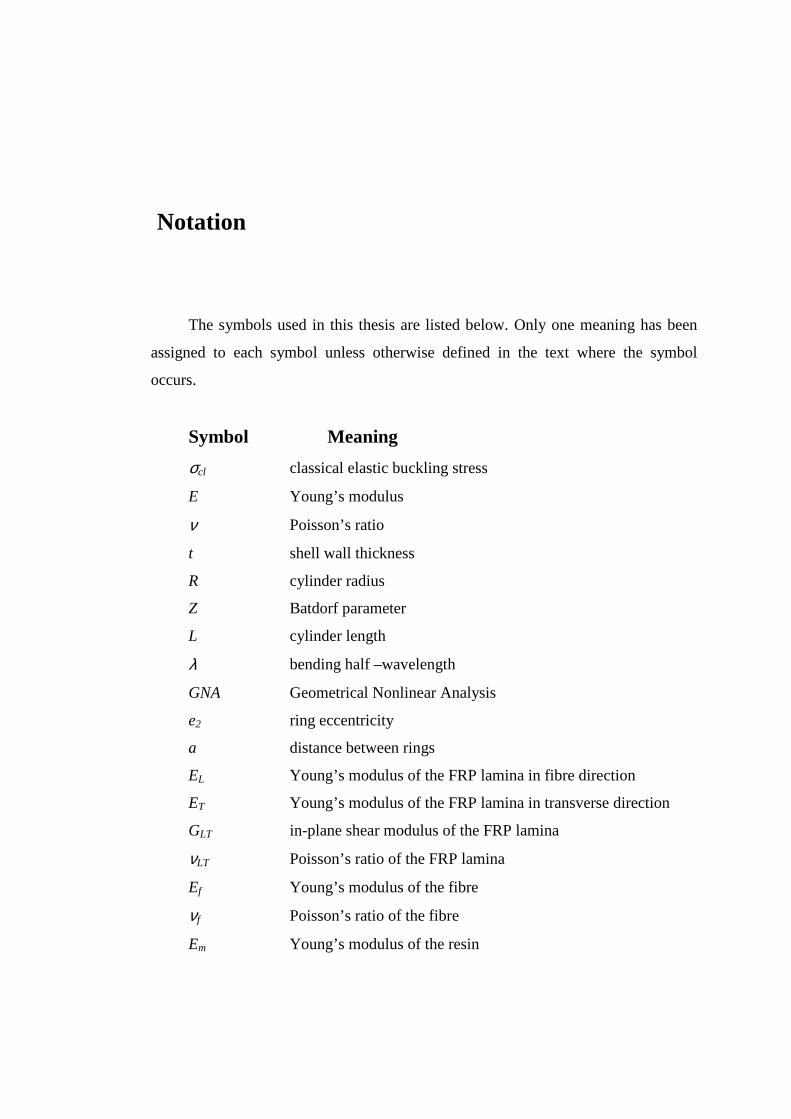
The symbols used in this thesis are listed below. Only one meaning has been
assigned to each symbol unless otherwise defined in the text where the symbol
occurs.
Symbol Meaning
σcl classical elastic buckling stress
E Young’s modulus
ν Poisson’s ratio
t shell wall thickness
R cylinder radius
Z Batdorf parameter
L cylinder length
λ bending half –wavelength
GNA Geometrical Nonlinear Analysis
e2 ring eccentricity
a distance between rings
EL Young’s modulus of the FRP lamina in fibre direction
ET Young’s modulus of the FRP lamina in transverse direction
GLT in-plane shear modulus of the FRP lamina
νLT Poisson’s ratio of the FRP lamina
Ef Young’s modulus of the fibre
νf Poisson’s ratio of the fibre
Em Young’s modulus of the resin
Gm shear modulus of the resin
νm Poisson’s ratio of the resin
Vf fibre volume friction
Vm matrix volume friction
Wf fibre weight
[T] transformation matrix from (θ,z) coordinate system to (L,T)
coordinate system
[Q] stiffness matrix
{κ} the change of curvature
{ε} strain matrix in the reference surface.
[A] in-plane stiffness matrix
[B] extension-bending coupling matrix
[D] bending stiffness matrix
]~
[D modified bending stiffness ( ][][][][]~
[ 1 BABDD T −−= )
Bθ extensional stiffness of a layered shell in circumferential
direction
Bz extensional stiffness of a layered shell in meridional direction
Cθz shear stiffness of a layered shell in (θ, z) plane.
Dθ bending stiffness of a layered shell in circumferential direction
Dz bending stiffness of a layered shell in meridional direction
Dθz twisting stiffness of a layered shell
µθ Poisson’s ratios associated with bending in circumferential
direction
µz Poisson’s ratios associated with bending in meridional
direction
µ’ θ Poisson’s ratios associated with extension in circumferential
direction
µ’ z Poisson’s ratios associated with extension in meridional
direction
h height of the cylindrical shell
ts thickness of the metal cylinder
Es Young’s modulus of the metal cylinder
νs Poison’s ratio of the metal cylinder
hf height of FRP sheet
tf Thickness of FRP sheet
xf starting distance of FRP sheet above the base
Efθ Young’s modulus of FRP sheet in the circumferential direction
Efz Young’s modulus of FRP sheet in the meridional direction
νfθ Poisson’s ratio of FRP sheet in the circumferential direction
p uniform internal pressure
Nz vertical load per unit circumference
w radial displacement
β circumferential rotation
D shell flexural rigidity
Ds shell flexural rigidity for the metal.
Dfz shell flexural rigidity of FRP sheet in meridional direction.
Nzs axial force in the cylindrical metal shell.
Nzf axial force in the FRP shell.
α extensional stiffness ratio (Efθtf/Ests)
tb effective thickness for the composite FRP-steel section.
LA Linear elastic Analysis
GMNA Geometrically and Materially Nonlinear Analysis
GNIA Geometrically Nonlinear Analysis with Imperfections
wm membrane theory normal deflection
λb meridional bending half-wavelength for the composite FRP-
steel section.
wmb membrane theory normal deflection for the composite FRP-
steel section.
Nθ circumferential stress resultant
Mz bending moment in meridional direction
Mθ bending moment in meridional direction
Qz shear stress resultant in meridional direction
σvM von Mises stress
σmz meridional membrane stress.
σmθ circumferential membrane stress
σbz meridional bending stress
σvM0 membrane von Mises
αz meridional elastic imperfection factor
kw∆ characteristic imperfection amplitude
Q meridional compression fabrication quality parameter
δ0 imperfection amplitude
λ0 half wavelength for the adopted shape of imperfection.
y circumferential coordinate from the centre of the dent (y=Rθ )
Lz half wavelength characterising the dent height.
Lθ half wavelength characterising the width of the rectangular
dent.
Lsq square dent dimension
Lsqm critical square dent size
ncl buckling mode wave number of the perfect cylinder
Lzw dent height in the Wullschleger (2006) study
Lθw dent width in the Wullschleger (2006) study
∗0δ
marginal initial dent amplitude for the critical dimensions in
the Wullschleger (2006) study.
1
Contents
Chapter 1...................................................................................................................... 4
Introduction 4
1.1 General background on steel silos 4
1.2 General background on fibre reinforced polymer, FRP 6
1.3 Objectives and scope of this thesis 7
1.4 Structures of the thesis 8
Chapter 2.................................................................................................................... 10
Literature review 10
2.1 Introduction 10
2.2 Buckling of thin cylindrical shells 11
2.3 Typical techniques for strengthening cylindrical shells against
buckling 17
2.4 FRP composites to strengthen structures 21
2.5 FRP strengthening of a metallic cylindrical shell 24
2.6 Summary 25
Chapter 3.................................................................................................................... 26
Mechanical Properties of FRP composites 26
3.1 Introduction 26
3.2 Mechanical properties of FRP lamina 26
3.3 The effect of the orientation of the fibres 30
3.4 The mechanical properties of layered FRP composites 31
Chapter 4.................................................................................................................... 35

2
FRP preventing radial displacements in pressurized
cylinders, Linear elastic Analysis (LA) 35
4.1 Introduction 35
4.2 Stress resultants in a cylindrical shell strengthened with an FRP
sheet 36
4.3 Patterns of deformation in the shell 48
4.4 Optimal FRP strengthening to decrease the radial displacement 50
4.5 A cylindrical shell with a fixed base 54
4.6 Summary 59
Chapter 5.................................................................................................................... 60
Strengthening cylindrical shells against elephant’s foot
buckling using FRP 60
5.1 Introduction 60
5.2 Elephant’s foot buckling 61
5.3 Finite element analysis procedures 63
5.4 Strengthening the cylindrical shell using FRP 67
5.5 Optimal dimensions of FRP sheet for strengthening a cylinder
against elephant’s foot collapse 71
5.6 Empirical formulas for the optimal attached FRP 75
5.7 Summary 80
Chapter 6.................................................................................................................... 81
Elastic buckling of FRP-strengthened cylinders with
axisymmetric imperfections 81
6.1 Introduction 81
6.2 Bifurcation buckling stress of a cylinder with a local axisymmetric
imperfection 82
6.3 Finite element analysis procedures 84
6.4 Buckling stress of FRP strengthened imperfect cylindrical shell 91
6.5 Summary 104
Chapter 7.................................................................................................................. 105
3
Using FRP in strengthening the elastic buckling of thin
metallic cylinders with single local dent 105
7.1 Introduction 105
7.2 Finite element analysis procedures 106
7.3 Previous experimental study and comparison 108
7.4 Buckling of unstrengthened cylinders with a dent 111
7.5 Buckling of FRP-Strengthened cylinder with a dent 120
7.6 Summary 126
Chapter 8.................................................................................................................. 128
Conclusions and recommendations 128
8.1 Summary 128
8.2 FRP preventing radial displacements in pressurized cylinders,
Linear elastic Analysis (LA) 129
8.3 Strengthening cylindrical shells against elephant’s foot buckling
using FRP 130
8.4 Elastic buckling of FRP-strengthened cylinders with axisymmetric
imperfections 131
8.5 Using FRP in strengthening the elastic buckling of thin metallic
cylinders with single local dent 132
8.6 Recommendations for future work 134
References 136
Appendix I 144
Appendix II 147
4
Chapter 1
Introduction
1.1 General background on steel silos
Steel silos are widely used as long-term or short-term containers for the storage
of granular solids. Granular solids cover a huge range of materials such as flour, iron
ore pellets, coals, cement, crushed rocks, plastic, chemical materials, sand, concrete
aggregate, etc.
The plan form of silos can take a rectangular shape or a circular shape; the
latter covers the majority of steel silos as it is structurally more efficient.
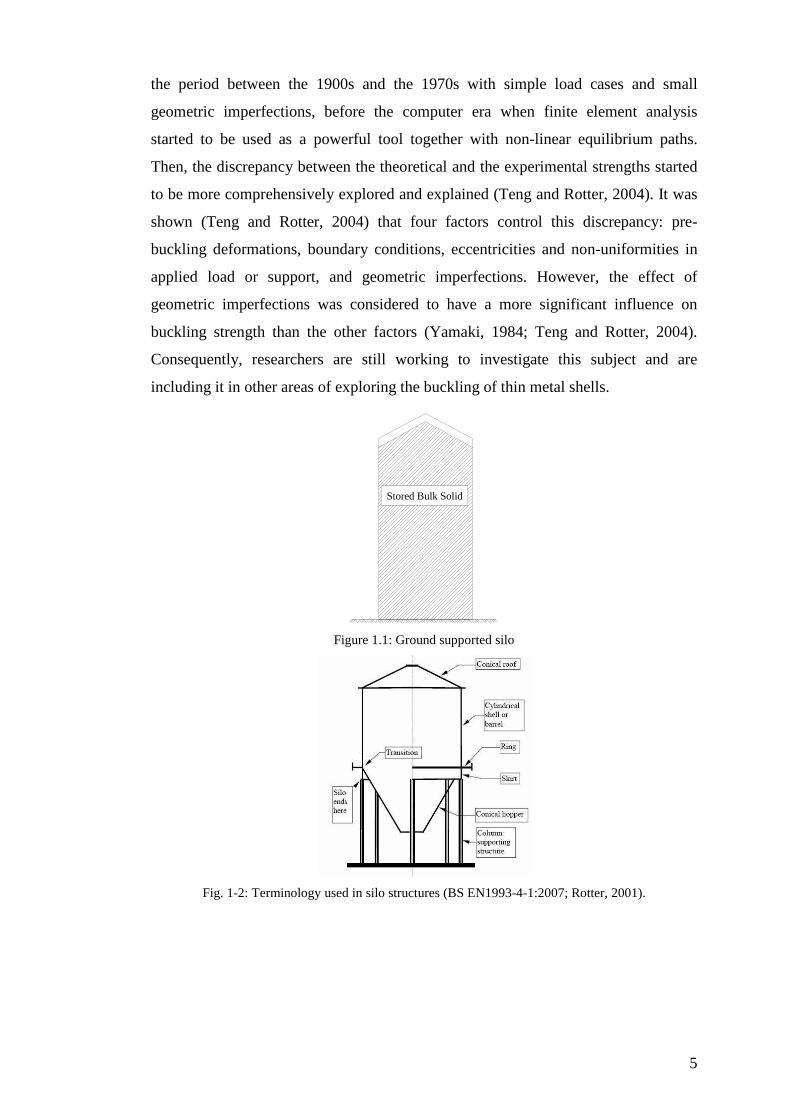
In general, silos can be divided into two categories: ground-supported silos
(Fig.1-1) or elevated silos which consist of cylindrical shell, barrel, and a conical
hopper (Fig.1-2). The second category is preferred because the bulk solid can be
discharged by gravity flow. However, elevated silos are supported to the ground
using a long skirt or columns which can be terminated below the transition, extended
to the top ring or terminated part way into the cylinder. It is worth mentioning that
the radius to thickness ratio for silos is in the range of 200 to 3000. Therefore, silos
fall into the category of thin wall shells where buckling failure is the main concern
and demands special attention.
The buckling of a thin metal shell has been studied scientifically since the early
twentieth century (Timoshenko, 1936). The classical period of those studies refers to
5
the period between the 1900s and the 1970s with simple load cases and small
geometric imperfections, before the computer era when finite element analysis
started to be used as a powerful tool together with non-linear equilibrium paths.
Then, the discrepancy between the theoretical and the experimental strengths started
to be more comprehensively explored and explained (Teng and Rotter, 2004). It was
shown (Teng and Rotter, 2004) that four factors control this discrepancy: pre-
buckling deformations, boundary conditions, eccentricities and non-uniformities in
applied load or support, and geometric imperfections. However, the effect of
geometric imperfections was considered to have a more significant influence on
buckling strength than the other factors (Yamaki, 1984; Teng and Rotter, 2004).
Consequently, researchers are still working to investigate this subject and are
including it in other areas of exploring the buckling of thin metal shells.
Stored Bulk Solid
Figure 1.1: Ground supported silo
Fig. 1-2: Terminology used in silo structures (BS EN1993-4-1:2007; Rotter, 2001).

6
Strengthening metal shells against buckling was to become the concern of
many researchers. Ring stiffeners and stringers were used widely (Singer, 2004). The
purpose of ring stiffeners is to increase the buckling strength, whereas the role of
stringers is to increase the axial or bending strength (Singer, 2004). Moreover, the
effect of the position of the ring or stringer inside or outside the silo on the buckling
strength was a field to be explored by many researchers (Singer et al., 1966). It was
seen that both cylindrical shell length and boundary conditions affect the buckling
strength. For instance, using the outside ring is more effective for short shells (Singer
et al., 1966). Another example is end rotational restraint is effective for short
stringer-stiffened cylindrical shells, while by contrast the axial restraint is more
important for long ones (Singer et al., 1967).
1.2 General background on fibre reinforced polymer, FRP
Fibre reinforced polymer, FRP, is composed of two principal elements: fibres
and resin material, where the fibres give FRP the strength, whereas the resin binds
the fibres together. The fibres are made from carbon, aramid or glass. Therefore, the
strength can be varied, depending on the kind of fibres used in making FRP.
However, the strength of FRP can be at least twice, and as much as 10 times as
strong as steel plates.
The advantages of using FRP as a strengthening technique can be stated as
follows (Cripps, 2002; Teng et al., 2002; Technical report No. 55 of Concrete
Society, 2004):
High strength to weight ratio: Lifting equipment eliminated; reduced labour
cost, speedy application; minimal increases in weight and size
Durable performance: many examples show that external GFRP cladding units
which are 25 years old or more are still looking good. However, regular re-painting
is required.
Flexibility of shape: can be handled in rolls; easy for wrapping on curved
surfaces and around columns and shells.
Non-conducting and non magnetic: safety in high powered electrical systems,
except carbon fibre.
Easily cut to length on site.

7
Overlapping ability because the material is thin.
Increasing the ductility of the element, consequently effective seismic
resistance.
Applying to the external surface with no need of access to the interior in the
case of storage structures.
The chief disadvantages of using FRP are: first; the environmental impact with
chemical-producing FRP and difficulties in recycling. Moreover, the resins absorb
water, and the moisture affects the properties of FRP if it reaches the fibre/matrix
interfaces. However, modern FRP versions are less sensitive to moisture or
temperature. Secondly; there is the problem of fire where most polymers will burn
when exposed to fire.
FRP is linear elastic with no stress redistribution because FRP has a straight
line stress-strain response with no yielding until rupture. Further, the compressive
strengths of carbon and glass fibres are close to their tensile strengths; that of aramid
is significantly lower in compression (Technical report No. 55 of Concrete Society,
2004).
The first use of FRP to strengthen structures was with concrete elements;
extensive research has been undertaken in this area since the 1990s (Teng et al.,
2002). This FRP research has been extended to the strengthening of metallic beams,
masonry and timber structures (Triantafillou, 1998; Gilfillan, 2003; Cadei et al.,
2004). In all these cases, strength, rather than stability, was the main concern. The
use of FRP to increase the buckling strength of thin metallic shells has scarcely been
explored at all.
1.3 Objectives and scope of this thesis
The primary aim of this study is to investigate the application of FRP to
increase the buckling capacity of thin metallic cylindrical shells.
The work presented in this thesis may be conveniently divided into two
conditions for cylindrical shell buckling: internal pressure accompanied by axial
load, and axial loads with geometric imperfections.
Thin cylindrical shells are sensitive to the magnitude of the imperfections,
which can cause elastic buckling near a local imperfection if the internal pressure is

8
small, but under high internal pressure, this sensitivity is much reduced. It was
shown (Rotter, 1990; Teng and Rotter, 1992) that elastic-plastic buckling occurs
under high internal pressure with a local reduction of the flexural stiffness due to
plasticity near the boundary conditions. Under this local reduction, an increase in the
radial displacements leads to a rise in the circumferential membrane stress resultant,
and elastic-plastic collapse, known as elephant’s foot buckling, results (Rotter,
1990).
Linear elastic shell Analysis, LA, and Geometrically and Materially Nonlinear
Analysis, GMNA, are used in this thesis to show that a small amount of FRP, placed
at the critical location, can significantly decrease the radial deformation of the shell,
leading to an increase of the elephant's foot buckling strength.
In the second set of studies, Geometrically Nonlinear elastic Analysis with
Imperfections included, GNIA, is considered when exploring the elastic buckling
strength of an FRP strengthened cylindrical shell under axial loads only with both
axisymmetric inward imperfections and local dents.
1.4 Structures of the thesis
The thesis is divided into seven chapters. A brief description for each chapter is
presented below:
Chapter 1 introduces the background to the many ideas used in this thesis, the
objectives and scope of this research and the structure of the thesis.
Chapter 2 reviews the literature relating to this study. It describes the historical
background to the buckling of cylindrical shells, FRP strengthened structures and
FRP strengthening of metallic shells.
Chapter 3 gives a brief review of FRP properties and modelling. It describes
the principles which need to be considered when the FRP is analysed.
Chapter 4 presents a preliminary study of the strengthening of pressurized
cylindrical shells using externally bonded FRP. The linear elastic equations for the
strengthened cylinder are derived for both pinned and fixed base boundary
conditions. In addition, the optimal dimensions of the FRP sheet together with the
critical location are obtained to prevent a local peak radial displacement from
occurring.

9
Chapter 5 explores the use of FRP to strengthen a thin cylindrical shell against
elephant’s foot buckling. In this chapter, geometrically and materially nonlinear
analysis is undertaken to explore the effectiveness of an FRP sheet against elephant’s
foot buckling. As in chapter 4, the optimal FRP dimensions are derived for this case
too.
Chapter 6 examines the elastic buckling strength of an FRP strengthened
cylindrical shell with axisymmetric inward imperfections under axial loads. In this
chapter, the effects of the amplitude of the imperfection, the FRP stiffness and the
FRP height are investigated.
Chapter 7 presents the buckling behaviour of a cylindrical metal shell with a
dent, and strengthened with FRP. Different amplitudes of the initial depth of the dent
are studied and the elastic buckling strength is found for different dimensions of the
dent. The strengthening of a rectangular dent using FRP is studied as an example.
For this case, both different FRP sheet stiffness and FRP sheet dimensions are
investigated to optimise the gain in buckling strength.
Chapter 8 presents the conclusions drawn from the previous chapters.
Recommendations for further research are also made.
10
Chapter 2
Literature review
2.1 Introduction
As indicated in Section 1.3, the primary aim of this thesis is to explore the
buckling capacity of thin metal cylindrical shells using FRP.
Therefore, this chapter starts with a description of the most relevant works in
the area of buckling of cylindrical shells. In this thesis, the focus is on two conditions
in cylindrical shells: internal pressure accompanied by axial load and axial loads with
geometric imperfections. The content of this chapter reflects this focus.
Background information on the strengthening of cylindrical shells is given, and
some typical techniques are discussed for preventing the collapse of the cylindrical
shells.
Previous studies of the application of FRP composites to strengthen structures
are identified. Current work on the strengthening of cylindrical shells against
buckling using FRP is also described.
Finally, a summary of this chapter is given, identifying the new studies
presented in this thesis.
11
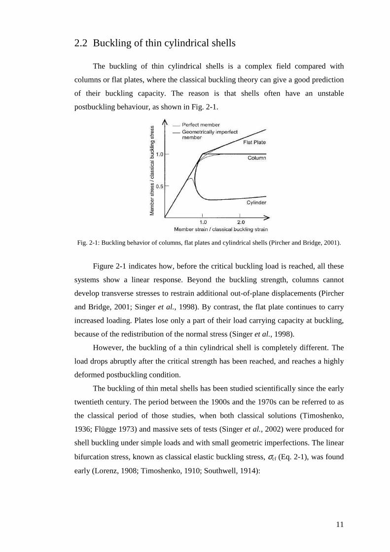
2.2 Buckling of thin cylindrical shells
The buckling of thin cylindrical shells is a complex field compared with
columns or flat plates, where the classical buckling theory can give a good prediction
of their buckling capacity. The reason is that shells often have an unstable
postbuckling behaviour, as shown in Fig. 2-1.
Fig. 2-1: Buckling behavior of columns, flat plates and cylindrical shells (Pircher and Bridge, 2001).
Figure 2-1 indicates how, before the critical buckling load is reached, all these
systems show a linear response. Beyond the buckling strength, columns cannot
develop transverse stresses to restrain additional out-of-plane displacements (Pircher
and Bridge, 2001; Singer et al., 1998). By contrast, the flat plate continues to carry
increased loading. Plates lose only a part of their load carrying capacity at buckling,
because of the redistribution of the normal stress (Singer et al., 1998).
However, the buckling of a thin cylindrical shell is completely different. The
load drops abruptly after the critical strength has been reached, and reaches a highly
deformed postbuckling condition.
The buckling of thin metal shells has been studied scientifically since the early
twentieth century. The period between the 1900s and the 1970s can be referred to as
the classical period of those studies, when both classical solutions (Timoshenko,
1936; Flügge 1973) and massive sets of tests (Singer et al., 2002) were produced for
shell buckling under simple loads and with small geometric imperfections. The linear
bifurcation stress, known as classical elastic buckling stress, σcl (Eq. 2-1), was found
early (Lorenz, 1908; Timoshenko, 1910; Southwell, 1914):
12
R
tE
R
tEcl 605.0
)]1(3[ 2/12≈
−=
νσ (2-1)
in which E is Young’s modulus, ν is Poisson’s ratio (around 0.3 for steel), t is the
shell wall thickness and R is the cylinder radius.
However, the discrepancy between the classical theory strength and the test
was too great to be accepted, and was affected by one of four factors (Teng and
Rotter, 2004):
Prebuckling deformations and their contributions in changing the stress.
Boundary conditions.
Eccentricities and non-uniformities in applied load or support.
Geometric imperfections and residual stresses.
Since then, the computer era has given researchers a huge motivation to
acquire more understanding about this discrepancy. The application of finite element
analysis, together with non-linear equilibrium paths, was a valuable step to find the
answers to many questions.
Studies of prebuckling deformations show that they have a small effect (~15%)
on the difference between the theory and tests (Teng and Rotter, 2004).
The effect of the boundary conditions was explored extensively. Yamaki
(1984) presented different boundary conditions, described in Table 2-1 below. The
boundary conditions were found to have very little influence on buckling strength,
with the fact that most cylindrical shells fall into the category of medium length, as
described in Eurocode 3 Part 1.6 (2007).
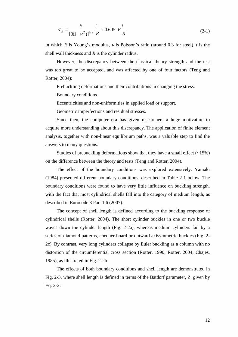
The concept of shell length is defined according to the buckling response of
cylindrical shells (Rotter, 2004). The short cylinder buckles in one or two buckle
waves down the cylinder length (Fig. 2-2a), whereas medium cylinders fail by a
series of diamond patterns, chequer-board or outward axisymmetric buckles (Fig. 2-
2c). By contrast, very long cylinders collapse by Euler buckling as a column with no
distortion of the circumferential cross section (Rotter, 1990; Rotter, 2004; Chajes,
1985), as illustrated in Fig. 2-2b.
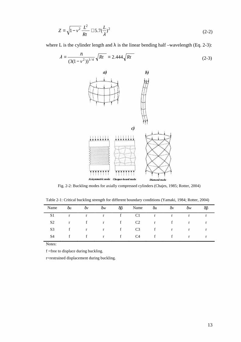
The effects of both boundary conditions and shell length are demonstrated in
Fig. 2-3, where shell length is defined in terms of the Batdorf parameter, Z, given by
Eq. 2-2:
13
22
2 )(7.51λL
Rt
LvZ ≅−= (2-2)
where L is the cylinder length and λ is the linear bending half –wavelength (Eq. 2-3):
RtRtv
444.2))1(3( 4/12
=−
= πλ (2-3)
Fig. 2-2: Buckling modes for axially compressed cylinders (Chajes, 1985; Rotter, 2004)
Table 2-1: Critical buckling strength for different boundary conditions (Yamaki, 1984; Rotter, 2004)
Name δu δv δw δβ Name δu δv δw δβ
S1 r r r f C1 r r r r
S2 r f r f C2 r f r r
S3 f r r f C3 f r r r
S4 f f r f C4 f f r r
Notes:
f =free to displace during buckling.
r=restrained displacement during buckling.
14
Fig. 2-3: Effect of boundary conditions and shell length on perfect elastic shell buckling load (Rotter,
2004; Yamaki, 1984)
For medium length cylinder (Z>50, Λ<1), the boundary conditions have little
effect on buckling strength, except for the boundary conditions S2 and S4 (Fig. 2-3).
Figure 2-3 also shows that prebuckling deformations affect the buckling strength by
about 8% for C1 to 17% for S3 from the classical value. Further, when the
circumferential displacements, δv, are not restrained for the pinned boundary
condition (S2 and S4), the buckling stress for the perfect shell falls to about half of
its classical strength. Short elastic cylinders provide high buckling strength, as seen
in Fig. 2-3.
2.2.1 Imperfect cylinders
The effect of geometric imperfections was considered to have a very
significant influence on buckling strength. A lap joint (Rotter and Teng, 1989;
Rotter, 1998; 2004) causes a local eccentricity in the thrust of vertical line in the
cylinder wall and consequently produces a local bending moment. In addition, the
moving of the shell inwards and outwards brings local membrane circumferential
stresses to be combined to the membrane meridional stresses, causing buckling
failure. The shape of imperfections was studied extensively to show that local
axisymmetric imperfections give a dramatic reduction to the buckling strength under
15
pure axial load (Rotter and Teng, 1989; Rotter, 1996; 2004). In addition, it was seen
that the elastic buckling strength is independent of radius to thickness ratio (Rotter
and Teng, 1989). Moreover, the boundary conditions are not important for the
buckling strength with imperfections far away from the ends (Rotter, 1997; Pircher
and Bridge, 2001).
For internally pressurized cylinders, the collapse load is less sensitive to the
wall imperfections (Rotter, 1990; Teng and Rotter, 1992). Changing the buckling
mode from diamond to a very local axisymmetric at high internal pressure reduces
the imperfection sensitivity (Rotter and Teng, 1989; Rotter, 1990; Rotter and Zhang,
1990). Plastic instability occurs in the region of local bending near the boundary
condition. This leads to more stable postbuckling behaviour (Rotter, 2004). Rotter
(1997) showed that unpressurized cylinders with radius to thickness ratio, R/t, less
than 400 buckle plastically. Moreover, Rotter and Teng (1989) presented that the
meridional form of the buckling mode is very localized in thin shells, while thick
shells provide a buckling mode for the whole shell, so the boundary conditions
become important.
2.2.2 Non-uniform loads in silo design
Non-uniformly loads need to be considered when the buckling design of a silo
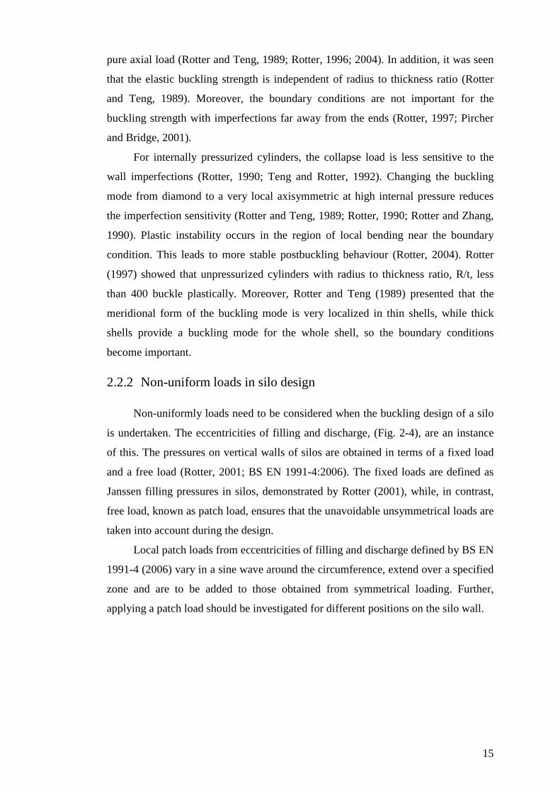
is undertaken. The eccentricities of filling and discharge, (Fig. 2-4), are an instance
of this. The pressures on vertical walls of silos are obtained in terms of a fixed load
and a free load (Rotter, 2001; BS EN 1991-4:2006). The fixed loads are defined as
Janssen filling pressures in silos, demonstrated by Rotter (2001), while, in contrast,
free load, known as patch load, ensures that the unavoidable unsymmetrical loads are
taken into account during the design.
Local patch loads from eccentricities of filling and discharge defined by BS EN
1991-4 (2006) vary in a sine wave around the circumference, extend over a specified
zone and are to be added to those obtained from symmetrical loading. Further,
applying a patch load should be investigated for different positions on the silo wall.
16
Fig. 2-4: Eccentricities of filling and discharge (Rotter, 2001).
Gillie and Rotter (2002) explored the effect of changing the circumferential
width, the vertical extent and the pressure distribution form for the patch load. It was
found that the silo responds as there is a point load when the patch load is small. In
contrast, a wide patch load causes the silo to behave as if a distributed load is
applied. Moreover, a patch load wider than 30° provides circumferential membrane
stresses which are independent of the patch size or application height.
Wind load is another example of the effect of non-uniform loads. Wind
pressures on a silo wall have been studied widely (Greiner, 1998). Greiner and
Guggenberger (2004) found that buckling occurs in the mid-height region of the shell
in the stagnation zone. Also, Greiner and Derler (1995) showed that, for short shells,
buckling is governed by circumferential compression and the buckles cover the
whole height of the cylinder. For medium length cylinders, the classical buckling
analysis indicates that buckling occurs at the lower edge by shear and axial
compression or by a combination of both, but geometrical nonlinear analysis shows
that the buckles move to the mid height of the cylinder. Further, the buckling
strength is reduced to about 50% of the classical load. The importance of geometric
nonlinearity is obvious from that study.
17
2.3 Typical techniques for strengthening cylindrical shells
against buckling
Strengthening cylindrical shells against buckling has been extensively studied
by researchers. Ring stiffeners and stringers (longitudinal stiffeners) were used
widely as typical techniques for reinforcing cylindrical shells against buckling. Ring
stiffeners are used mainly to enhance the buckling resistance to external pressure,
while stringers are applied to increase the axial buckling strength efficiently (Singer,
2004). However, they may give much effective enhancement for the cylinder if they
act together (Singer et al., 2002). It was shown that buckles will occur in the wall if
the ring is stocky but shell wall is thin. However, the ring itself is susceptible to
buckling if it is made from slender plate or shell segments (Teng and Zhao, 2004).
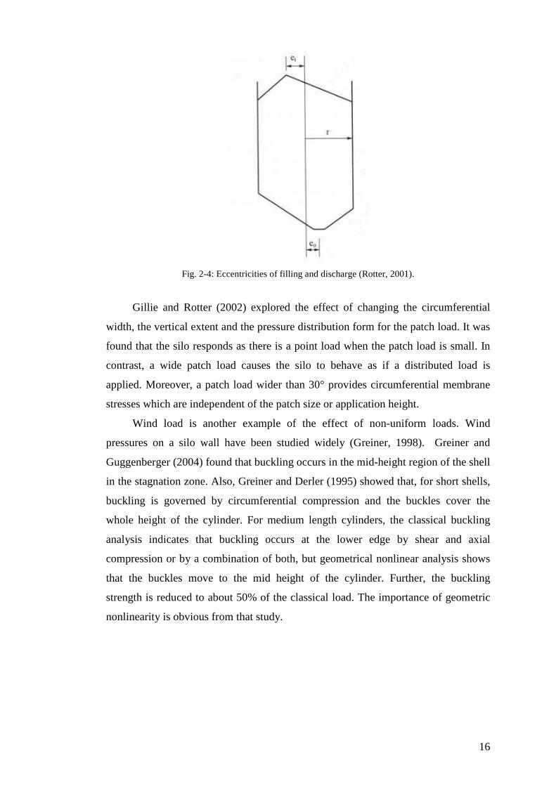
Singer (2004) and Singer et al. (2002) described the buckling modes of ring-stiffened
shells. They can be divided into three cases: local shell instability (Fig. 2-5a), overall
collapse (Fig. 2-5b) and axisymmetric plastic collapse (Fig. 2-5 c).
Fig. 2-5: Buckling cases for ring-stiffened shell (Singer, 2004).

18
In Fig. 2-5a, where the rings are widely spaced, local shell buckling occurs
between rings. For closely spaced internal rings (Fig. 2-5b), non-axisymmetric
buckling occurs and global instability takes place. By contrast, outside rings (Fig. 2-
5c) provide higher buckling strength by forcing an axisymmetric mode of collapse
(Singer, 2004). The position of the ring outside or inside the shell is important.
Rings are the most effective stiffeners for shells under external pressure. Figure
2-6 explores the influence of the ring area, A, on the buckling load (Singer et al.,
1966), where Puns.eq. is the buckling load for an unstiffened shell with equivalent
thickness of the same weight, e2 is the ring eccentricity to the centre of the shell wall
to be taken positive if the ring is inside and negative if the ring is outside, h is the
wall thickness and a is the distance between rings.
Fig. 2-6: Influence of ring area on the buckling strength for shell under hydrostatic pressure (Singer et
al., 1966).
In short shells when Z (Eq. 2-2) is small, the smallest rings are the best, but a
heavy ring, A2/ah=0.8, gives a higher buckling load for large Z. It appears that an
optimum area ratio can be obtained there. Singer et al. (1966) divided the effect of
the eccentricity of rings into two effects: a primary one where outside rings raise the
bending stiffness in the circumferential direction more than inside rings (necessary
for short cylinders) and a secondary effect where inside rings enhance the

19
extensional stiffness in the circumferential direction more than outside rings (for long
cylinders).
Stringers (longitudinal stiffeners) both increase the axial and bending strength.
Therefore, they are much more effective than rings for axial compression (Singer et
al., 1967). Cylinders with closely spaced stringers fail by global instability (Fig. 2-
7a). When the stringers are widely spaced, local buckling occurs between stringers
(Fig. 2-7b).
Fig. 2-7: Buckling forms for a stringer-stiffened cylindrical shell (Singer, 2004).
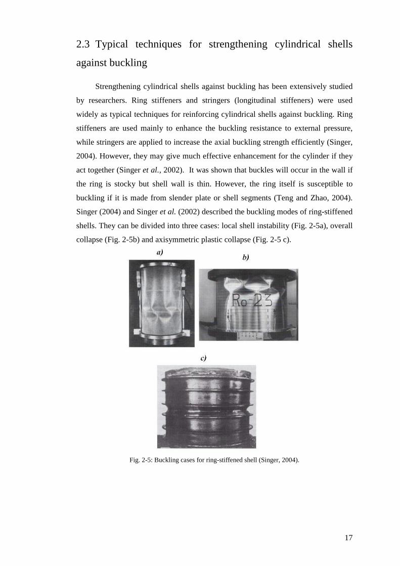
The position of stringers was discussed by Singer et al., (1967) showing that
outside stringers provide higher buckling loads than inside stringers when the shell is
short. Moreover, a clamped base is much better in this range (Fig. 2-8). The buckling
strength decreases rapidly for cylindrical shells of large Z. However, the curves in
Fig. 2-8 are calculated using linear buckling theory to obtain the buckling loads, and
the experiments on stiffened shells exhibit higher strengths than are shown in this
figure (Singer et al., 1967). In general, the studies of Singer and his co-authors show
that all practical outside stringer-stiffened shells give higher buckling loads than
inside ones.
20
Fig. 2-8: Buckling load of stringer-stiffened cylindrical shells under axial compression (Singer etal.,
1967)
2.3.1 End rings
It is worth mentioning that the upper end ring may have a good influence on
the buckling resistance. Rotter (1985a) indicated that the top ring has a strong
influence on the axial stress when applied pressures vary slowly around the
circumference (e.g. eccentric filling, wind, etc.). Greiner and Guggenberger (2004)
strongly recommended using a strong upper end-ring for thin walled cylindrical
shells under wind loads. It was found that it is not only necessary to take the wind
load over the upper half of the shell, but also to avoid global buckling in the
postbuckling range.
2.3.2 Using a ring to strengthen a cylinder locally
Under high internal pressure accompanied by axial forces, Chen et al., (2005,
2006) proposed that using a small ring stiffener is very effective in preventing
elastic-plastic failure by elephant’s foot buckling in cylindrical shells. Based on the

21
linear elastic bending theory (Rotter, 1985b), the optimal dimensions and location for
this stiffener were derived. It was seen that a ring that is either a larger ring or a
smaller than the optimal size may reduce the buckling strength. The same effect can
be seen in Fig. 2-6 (Singer, 1966) when the cylinder is long (large Z). In addition,
Greiner (2004) showed that, for a practical stepped wall cylinder under uniform
external pressure, a very small ring can raise the buckling resistance by about 50%
compared with an unstiffened shell. Further, Chen et al., (2005, 2006) showed that
the location of this ring should be chosen carefully. Otherwise, early elephant’s foot
buckling may occur.
2.4 FRP composites to strengthen structures
Fibre Reinforced Polymer (FRP) composites have been used widely in
construction for the last 30 years. Examples of FRP applications on buildings are
presented in many references (e.g. Cripps, 2002). FRP is composed of fibres
combined together by an appropriate resin which also plays a very significant role in
protecting the fibres from environmental effects. The most suitable fibres for
strengthening applications are shown in Table 2-2 where typical values of their
properties are given.
Table 2-2: Typical dry fibres properties (Concrete Society, 2004; Cadei et al., 2004)
Fibre
Tensile
strength
(MPa)
Modulus
of
elasticity
(GPa)
Strain to
failure
(%)
Density
(t/m3)
Coefficient
of thermal
expansion
(10-6/C)
Carbon: High strength 4300-4900 230-240 1.9-2.1 1.8 -0.38
Carbon: High modulus 2740-5490 294-329 0.7-1.9 1.78-1.81 -0.83
Carbon: Ultra high modulus 2600-4020 540-640 0.4-0.8 1.91-2.12 -1.1
Aramid: High strength and high
modulus 3200-3600 124-130 2.4 1.44 2.1
Glass 2400-3500 70-85 3.5-4.7 2.6 4.9
Table 2-2 shows that fibres with higher stiffness (elastic modulus) tend to have
smaller strength and failure strain.
22
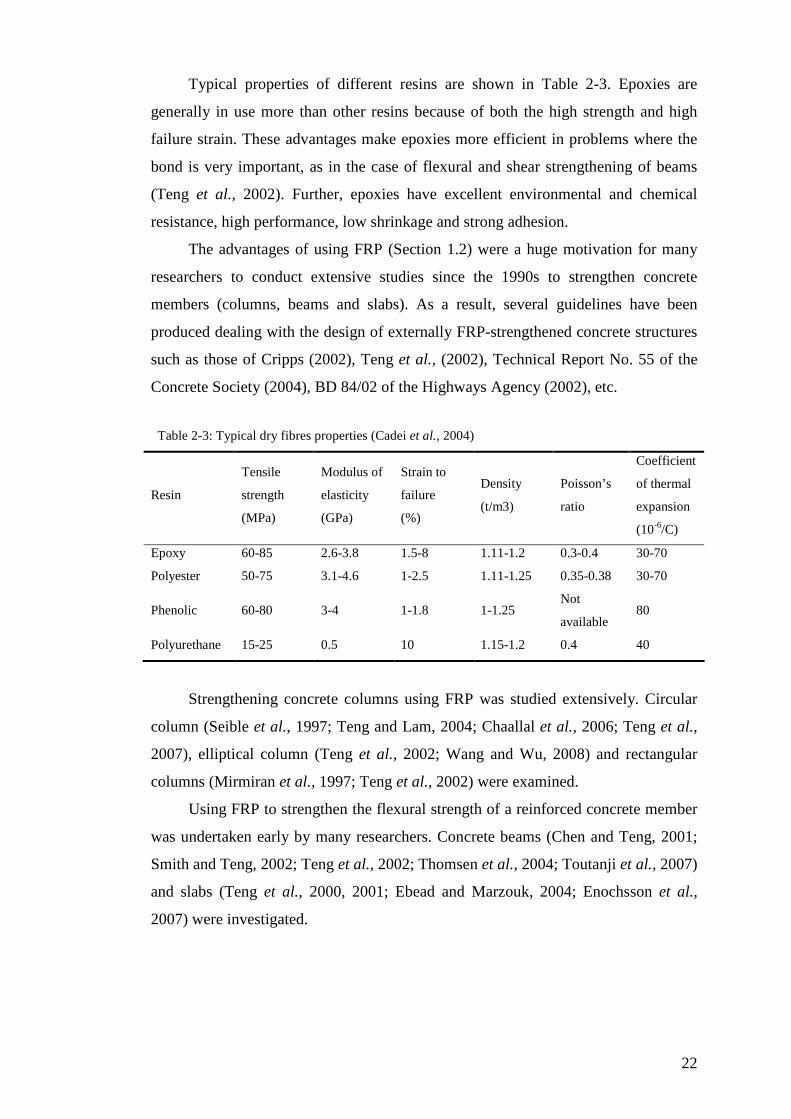
Typical properties of different resins are shown in Table 2-3. Epoxies are
generally in use more than other resins because of both the high strength and high
failure strain. These advantages make epoxies more efficient in problems where the
bond is very important, as in the case of flexural and shear strengthening of beams
(Teng et al., 2002). Further, epoxies have excellent environmental and chemical
resistance, high performance, low shrinkage and strong adhesion.
The advantages of using FRP (Section 1.2) were a huge motivation for many
researchers to conduct extensive studies since the 1990s to strengthen concrete
members (columns, beams and slabs). As a result, several guidelines have been
produced dealing with the design of externally FRP-strengthened concrete structures
such as those of Cripps (2002), Teng et al., (2002), Technical Report No. 55 of the
Concrete Society (2004), BD 84/02 of the Highways Agency (2002), etc.
Table 2-3: Typical dry fibres properties (Cadei et al., 2004)
Resin
Tensile
strength
(MPa)
Modulus of
elasticity
(GPa)
Strain to
failure
(%)
Density
(t/m3)
Poisson’s
ratio
Coefficient
of thermal
expansion
(10-6/C)
Epoxy 60-85 2.6-3.8 1.5-8 1.11-1.2 0.3-0.4 30-70
Polyester 50-75 3.1-4.6 1-2.5 1.11-1.25 0.35-0.38 30-70
Phenolic 60-80 3-4 1-1.8 1-1.25 Not
available 80
Polyurethane 15-25 0.5 10 1.15-1.2 0.4 40
Strengthening concrete columns using FRP was studied extensively. Circular
column (Seible et al., 1997; Teng and Lam, 2004; Chaallal et al., 2006; Teng et al.,
2007), elliptical column (Teng et al., 2002; Wang and Wu, 2008) and rectangular
columns (Mirmiran et al., 1997; Teng et al., 2002) were examined.
Using FRP to strengthen the flexural strength of a reinforced concrete member
was undertaken early by many researchers. Concrete beams (Chen and Teng, 2001;
Smith and Teng, 2002; Teng et al., 2002; Thomsen et al., 2004; Toutanji et al., 2007)
and slabs (Teng et al., 2000, 2001; Ebead and Marzouk, 2004; Enochsson et al.,
2007) were investigated.

23
The research on strengthening concrete structures has been extended to the
strengthening of masonry (Triantafillou, 1998; Chen, 2002) and timber structures
(Triantafillou, 1997; Gilfillan et al., 2003).
Strengthening metallic members using FRP has been the subject of a limited
amount of research. However, some effort has begun to compensate for this (e.g.
Cadei et al., 2004). Metallic beams have been the main concern recently (Photiou et
al., 2006; Stratford and Cadei, 2006). Photiou et al. (2006) explained that the type of
FRP fibres must be chosen carefully. The high modulus fibres, Table 2-2, produced
beams that displayed a ductile behaviour and higher flexural strength, whereas using
ultra high modulus fibres caused the beam to fail early by FRP rupture. The reason is
that the ultra high modulus fibres have a low ultimate strain (Table 2-2).
Furthermore, the final strength of the metallic beam depends completely on the
effectiveness of the adhesive. An elastic analysis study of the stresses in the adhesive
was conducted by Stratford and Cadei (2006). A high peel stress with a high shear
stress occurs at the end of the FRP strengthening plate. Changing the plate end
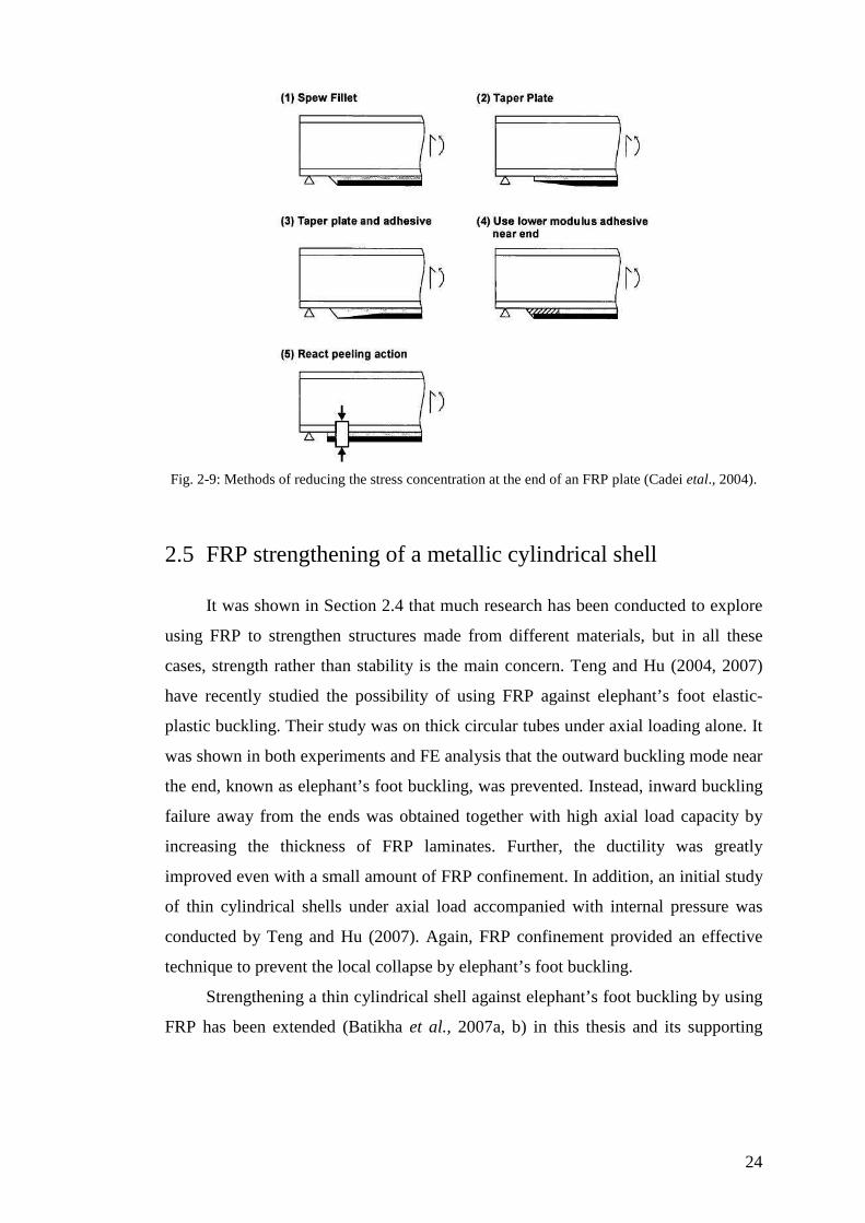
geometry and defect sensitivity were discussed by Stratford and Cadei (2006).
Methods of reducing the stress concentration at the end of an FRP plate are shown in
Fig. 2-9. Furthermore, by reducing the thickness of the FRP, while increasing its
width, the stresses in the adhesive can be decreased (Cadei et al., 2004; Stratford and
Cadei, 2006).
24
Fig. 2-9: Methods of reducing the stress concentration at the end of an FRP plate (Cadei etal., 2004).
2.5 FRP strengthening of a metallic cylindrical shell
It was shown in Section 2.4 that much research has been conducted to explore
using FRP to strengthen structures made from different materials, but in all these
cases, strength rather than stability is the main concern. Teng and Hu (2004, 2007)
have recently studied the possibility of using FRP against elephant’s foot elastic-
plastic buckling. Their study was on thick circular tubes under axial loading alone. It
was shown in both experiments and FE analysis that the outward buckling mode near
the end, known as elephant’s foot buckling, was prevented. Instead, inward buckling
failure away from the ends was obtained together with high axial load capacity by
increasing the thickness of FRP laminates. Further, the ductility was greatly
improved even with a small amount of FRP confinement. In addition, an initial study
of thin cylindrical shells under axial load accompanied with internal pressure was
conducted by Teng and Hu (2007). Again, FRP confinement provided an effective
technique to prevent the local collapse by elephant’s foot buckling.
Strengthening a thin cylindrical shell against elephant’s foot buckling by using
FRP has been extended (Batikha et al., 2007a, b) in this thesis and its supporting
25
papers. A linear elastic study (Batikha et al., 2007a) and a Geometrically and
Materially Nonlinear Analysis study (Batikha et al., 2007b) showed that a small
amount of FRP, placed at the critical location, can effectively eliminate elephant’s
foot buckling. In addition, elastic collapse of a thin cylindrical shell with an
axisymmetric imperfection and a local dent were discussed in Batikha et al. (2007c,
2008) respectively. These last two studies have shown that the strength of the
cylindrical shell can be effectively enhanced by bonding an external FRP locally
within the area of the imperfection zone.
2.6 Summary
In this chapter, the buckling of a thin cylindrical shell was reviewed with
typical methods of strengthening against stability failure. In addition, the new
technique of repairing structures using FRP was explored. Examples of using FRP to
strengthen concrete, masonry, timber and metallic members were provided. In all
these cases, the effectiveness of the FRP on the element strength was described.
Also, the study referred to the lack of research into the use of FRP to enhance the
stability of thin metal cylindrical shells. It can be seen that this study is valuable in
discovering the gain in buckling strength that a thin cylindrical shell can obtain under
different conditions.
26
Chapter 3
Mechanical Properties of FRP composites
3.1 Introduction
In this chapter, the mechanical properties of FRP composites are described.
This is vital background that must be understood before attempting to compute when
an FRP laminate may be useful. The area of concern in this chapter is FRP with
uniaxially aligned continues fibres.
This chapter begins with a description of the properties for one ply FRP with
uniaxial direction fibres. Secondly, the effect of the orientation of the fibres on the
mechanical properties of FRP ply is discussed. Finally, the properties of FRP sheet
consisting of many layers acting together are described.
3.2 Mechanical properties of FRP lamina
Fibre reinforce polymer, FRP, is formed from the fibres, denoted herby the
subscript f, and the resin known as the matrix, detonated by m. The arrangement of
the fibres into the FRP must be known in order to specify the mechanical properties
of FRP. Figure 3-1 shows the range of common fibre arrangements, although some
of these classes are not commonly used in practice (e.g. random fibres in three
dimensions) (McCrum et al., 1997). However, uniaxial fibres are the main focus of
this chapter (Fig. 3-2).

27
Fig. 3-1: Patterns of fibre arrangements (McCrum et al., 1997).
Fig. 3-2: The definition of axis for uniaxial fibre arrangements (Åström, 1997)
The uniaxial FRP lamina is considered as an orthotropic material in a planar
stress state where the differences between the properties of the fibres and the matrix
produce different engineering constants which are needed to model the material
behaviour.
The fibre spacing in the matrix can significantly influence the mechanical
properties of the FRP sheet, whether it is from a single isolated fibre or full contact
fibres in the matrix. Vinson and Sierakowski (1986) indicated that FRP plates
generally approach the behaviour of single fibres in practical situations. It should be
noted that most references derive the mechanical properties of an FRP lamina by
assuming the situation of isolated fibres (e.g. Åström, 1997; McCrum et al., 1997).
28
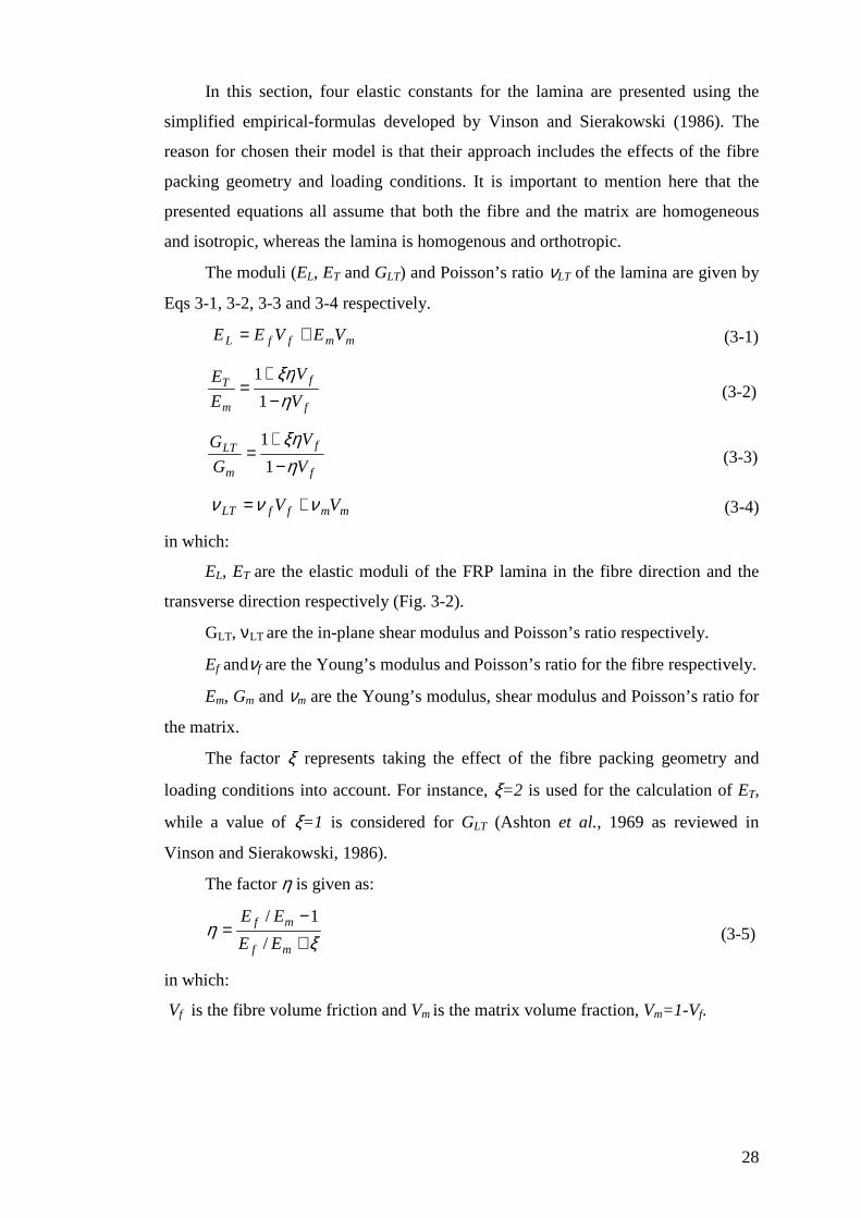
In this section, four elastic constants for the lamina are presented using the
simplified empirical-formulas developed by Vinson and Sierakowski (1986). The
reason for chosen their model is that their approach includes the effects of the fibre
packing geometry and loading conditions. It is important to mention here that the
presented equations all assume that both the fibre and the matrix are homogeneous
and isotropic, whereas the lamina is homogenous and orthotropic.
The moduli (EL, ET and GLT) and Poisson’s ratio νLT of the lamina are given by
Eqs 3-1, 3-2, 3-3 and 3-4 respectively.
mmffL VEVEE += (3-1)
f
f
m
T
V
V
E
E
ηξη
−+
=1
1 (3-2)
f
f
m
LT
V
V
G
G
ηξη
−+
=1
1 (3-3)
mmffLT VV ννν += (3-4)
in which:
EL, ET are the elastic moduli of the FRP lamina in the fibre direction and the
transverse direction respectively (Fig. 3-2).
GLT, νLT are the in-plane shear modulus and Poisson’s ratio respectively.
Ef andνf are the Young’s modulus and Poisson’s ratio for the fibre respectively.
Em, Gm and νm are the Young’s modulus, shear modulus and Poisson’s ratio for
the matrix.
The factor ξ represents taking the effect of the fibre packing geometry and
loading conditions into account. For instance, ξ=2 is used for the calculation of ET,
while a value of ξ=1 is considered for GLT (Ashton et al., 1969 as reviewed in
Vinson and Sierakowski, 1986).
The factor η is given as:
ξη
+−
=mf
mf
EE
EE
/
1/ (3-5)
in which:
Vf is the fibre volume friction and Vm is the matrix volume fraction, Vm=1-Vf.
29
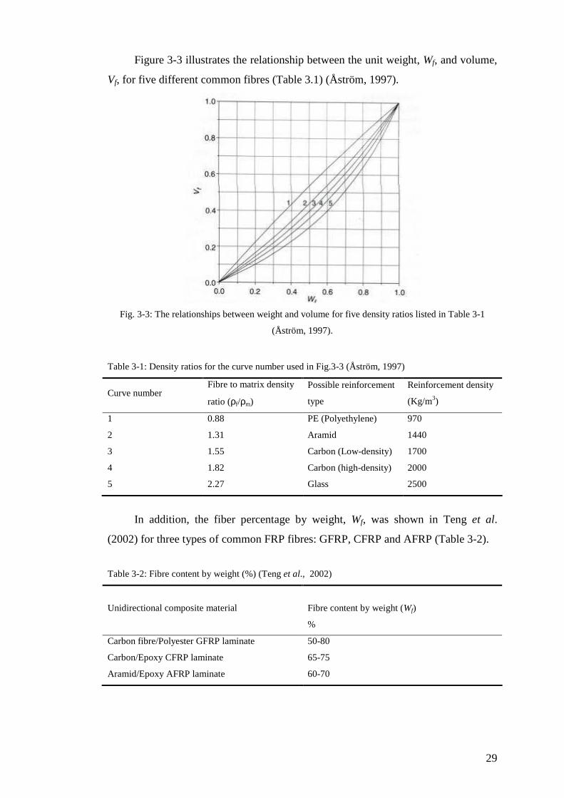
Figure 3-3 illustrates the relationship between the unit weight, Wf, and volume,
Vf, for five different common fibres (Table 3.1) (Åström, 1997).
Fig. 3-3: The relationships between weight and volume for five density ratios listed in Table 3-1
(Åström, 1997).
Table 3-1: Density ratios for the curve number used in Fig.3-3 (Åström, 1997)
Curve number Fibre to matrix density
ratio (ρf/ρm)
Possible reinforcement
type
Reinforcement density
(Kg/m3)
1 0.88 PE (Polyethylene) 970
2 1.31 Aramid 1440
3 1.55 Carbon (Low-density) 1700
4 1.82 Carbon (high-density) 2000
5 2.27 Glass 2500
In addition, the fiber percentage by weight, Wf, was shown in Teng et al.
(2002) for three types of common FRP fibres: GFRP, CFRP and AFRP (Table 3-2).
Table 3-2: Fibre content by weight (%) (Teng et al., 2002)
Unidirectional composite material
Fibre content by weight (Wf)
%
Carbon fibre/Polyester GFRP laminate 50-80
Carbon/Epoxy CFRP laminate 65-75
Aramid/Epoxy AFRP laminate 60-70

30
3.3 The effect of the orientation of the fibres
The fibres in the FRP lamina may be oriented in a direction which is not
parallel to the geometric axis of the beam, plate or shell (Fig. 3-4). For these
situations, new properties need to be obtained for an FRP lamina in the system
coordinates (z and θ in Fig. 3-4).
Fig. 3-4: Lamina coordinate systems.
The stresses and relative strains in the two coordinate systems shown in Fig. 3-
4 can be expressed as given in Eq. 3-6, (Vinson and Sierakowski, 1986; Zienkiewicz,
1971).
[ ]
=
z
z
LT
T
L
T
θ
θ
τσσ
τσσ
and [ ]
=
z
z
LT
T
L
T
θ
θ
γεε
γεε
(3-6)
where [T] is an appropriate transformation matrix given in Eq. 3-7:
−−−=
ββββββββββ
ββββ
22
22
22
sincossincossincos
sincos2cossin
sincos2sincos
][T (3-7)
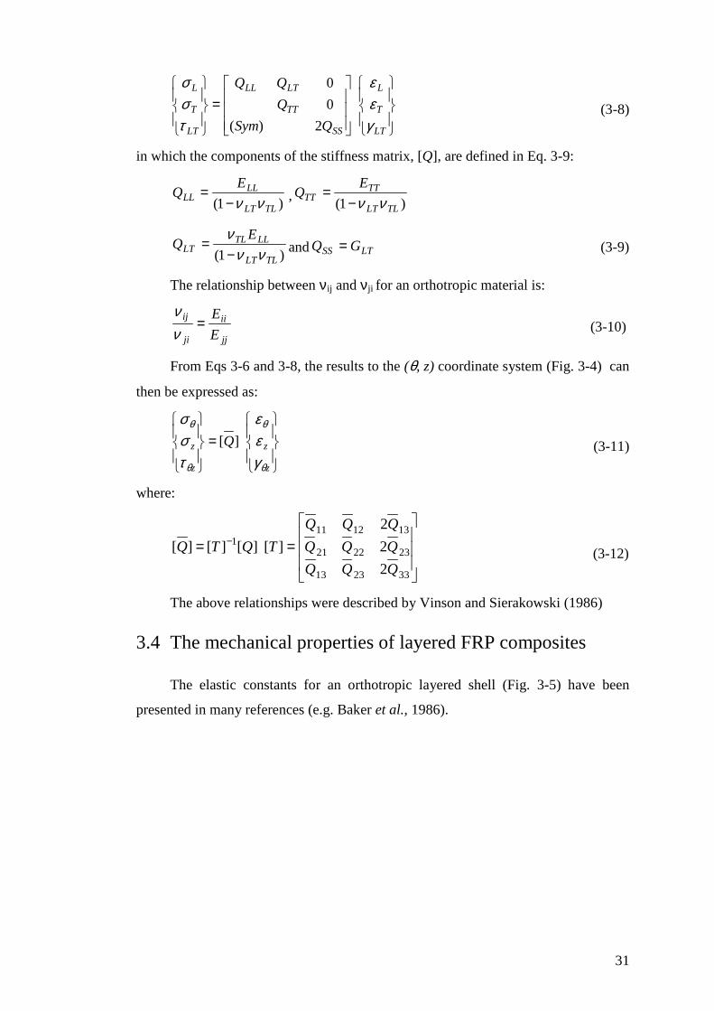
The relationship between stress and strain for an FRP lamina in terms of the
principal material direction (L, T) is shown in Eq. 3-8:
31
=
LT
T
L
SS
TT
LTLL
LT
T
L
QSym
Q
γεε
τσσ
2)(
0
0
(3-8)
in which the components of the stiffness matrix, [Q], are defined in Eq. 3-9:
)1( TLLT
LLLL
EQ
νν−= ,
)1( TLLT
TTTT
EQ
νν−=
)1( TLLT
LLTLLT
EQ
ννν−
= and LTSS GQ = (3-9)
The relationship between νij and νji for an orthotropic material is:
jj
ii
ji
ij
E
E=
νν
(3-10)
From Eqs 3-6 and 3-8, the results to the (θ, z) coordinate system (Fig. 3-4) can
then be expressed as:
=
z
z
z
z Q
θ
θ
θ
θ
γεε
τσσ
][ (3-11)
where:
== −
332313
232221
1312111
2
2
2
][][][][
QQQ
QQQ
QQQ
TQTQ (3-12)
The above relationships were described by Vinson and Sierakowski (1986)
3.4 The mechanical properties of layered FRP composites
The elastic constants for an orthotropic layered shell (Fig. 3-5) have been
presented in many references (e.g. Baker et al., 1986).

32
r1 r2 r3
r(n-
1)r(n)
1
2
3
n-1
n
Fig. 3-5: Layered shell
The relationship between the increments of stress resultant (membrane forces N
and bending/twisting moments M) and generalized strain (strain or change of
curvature) is linear (Geier and Singh, 1997; Geier et al., 2002):
}{][}{][}{ κε BAN += , }{][}{][}{ κε DBM T += (3-13)
in which:
{κ} is the change of curvature vector.
{ε} is the extensional strain vector.
[A], [B] and [D] are the in-plane stiffness matrix, the extension-bending
coupling matrix and the bending stiffness matrix respectively, given as follows for a
laminate of n layers (Fig. 3-5):
∑=
−−=n
kkkkijij rrQA
11)()( , [ ]
=
33
2322
131211
)( ASym
AA
AAA
A
∑=
−−=n
kkkkijij rrQB
1
21
2 )()(2
1, [ ]
=
33
2322
131211
)( BSym
BB
BBB
B and (3-14)
33
∑=
−−=n
kkkkijij rrQD
1
31
3 )()(3
1, [ ]
=
33
2322
131211
)( DSym
DD
DDD
D
where ijQ can be obtained from Eq.(3-12).
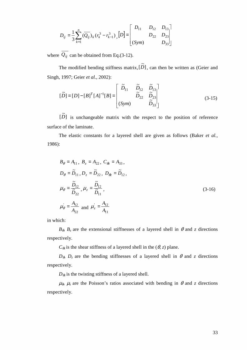
The modified bending stiffness matrix,]~
[D , can then be written as (Geier and
Singh, 1997; Geier et al., 2002):
=−= −
33
2322
1312111
~)(
~~
~~~
][][][][]~
[
DSym
DD
DDD
BABDD T (3-15)
]~
[D is unchangeable matrix with the respect to the position of reference
surface of the laminate.
The elastic constants for a layered shell are given as follows (Baker et al.,
1986):
11AB =θ , 22ABz = , 33AC z =θ ,
11~DD =θ , 22
~DDz = , 12
~DD z =θ ,
22
12~
~
D
D=θµ ,
11
12~
~
D
Dz =µ , (3-16)
22
12'
A
A=θµ and
11
12'
A
Az =µ
in which:
Bθ, Bz are the extensional stiffnesses of a layered shell in θ and z directions
respectively.
Cθz is the shear stiffness of a layered shell in the (θ, z) plane.
Dθ, Dz are the bending stiffnesses of a layered shell in θ and z directions
respectively.
Dθz is the twisting stiffness of a layered shell.
µθ, µz are the Poisson’s ratios associated with bending in θ and z directions
respectively.
34
µ’ θ, µ’ z are the Poisson’s ratios associated with extension in θ and z directions
respectively.
35
Chapter 4
FRP preventing radial displacements in pressurized
cylinders, Linear elastic Analysis (LA)
4.1 Introduction
In this chapter, FRP composites are applied to the external surface of a
cylindrical shell under internal pressure accompanied by an axial load. Linear elastic
shell Analysis (LA in the terminology of EN 1993-1-6, 2007) is used to investigate
the effectiveness of this application of FRP to decrease the lateral displacement of a
pressurised cylinder.
This chapter is divided into two parts:
First, a Linear elastic Analysis (LA) study is described in which the general
equations governing the behaviour of an FRP-strengthened cylindrical shell under
internal pressure accompanied by axial force are derived for different boundary
conditions.
Second, the effectiveness of the external FRP in reducing the radial
deformation of both pinned-base cylinder and fixed-base cylinders is explored. In
addition, both the optimal dimensions and the critical location of an FRP sheet are
obtained to prevent a peak from occurring in the radial displacement.
At the end of this chapter, a summary is given of the results established from
this linear elastic study.
36
4.2 Stress resultants in a cylindrical shell strengthened with an
FRP sheet
4.2.1 Geometry, boundary conditions, loading and material properties
A cylindrical shell of height h, radius r, and thickness ts is strengthened by
bonding FRP sheets to its exterior. The wall thickness of the cylindrical shell is
assumed to be constant over the whole structure. The Young’s modulus and the
Poisson’s ratio of the shell are Es and νs respectively.
The boundary condition at the bottom is first considered as simply supported
(radial, axial and circumferential displacements are restrained, but not the rotation) in
the following analysis, but a fixed support is also considered later. The top boundary
of the shell is assumed to be far away, so that the details of the boundary condition
are not important.
An FRP sheet with a height of hf and thickness of tf is bonded to the external
surface of the cylindrical shell, starting at a distance xf above the base. The FRP sheet
is treated as orthotropic with Young‘s modulus in the circumferential direction Efθ
and in the meridional direction Efz, with a Poisson’s ratio νfθ . It is assumed that the
FRP sheet consists of uniaxial fibres in the circumferential direction.
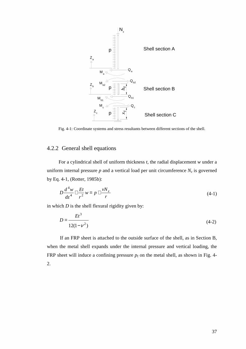
A uniform internal pressure p and an axial load per unit circumference Nz at the
top boundary are applied to the shell, as shown in Fig. 4-1. If the structure is a silo,
the vertical loads arise from the frictional drag of the stored material against the wall.
The internal pressure in the cylinder is assumed to be constant with the axial
coordinate, since the buckling mode is generally very localized (Rotter and Zhang
1990).
37
p
p
p
N
Shell section A
Shell section Cxh Shell section B
QM
Za
bZ
cZ
a
b2Q
Qb1
cQ
a
b2M
b1M
cM
z
ff
Fig. 4-1: Coordinate systems and stress resultants between different sections of the shell.
4.2.2 General shell equations
For a cylindrical shell of uniform thickness t, the radial displacement w under a
uniform internal pressure p and a vertical load per unit circumference Nz is governed
by Eq. 4-1, (Rotter, 1985b):
r
vNpw
r
Et
dz
wdD z+=+
24
4
(4-1)
in which D is the shell flexural rigidity given by:
)1(12 2
3
ν−=
EtD (4-2)
If an FRP sheet is attached to the outside surface of the shell, as in Section B,
when the metal shell expands under the internal pressure and vertical loading, the
FRP sheet will induce a confining pressure pf on the metal shell, as shown in Fig. 4-
2.
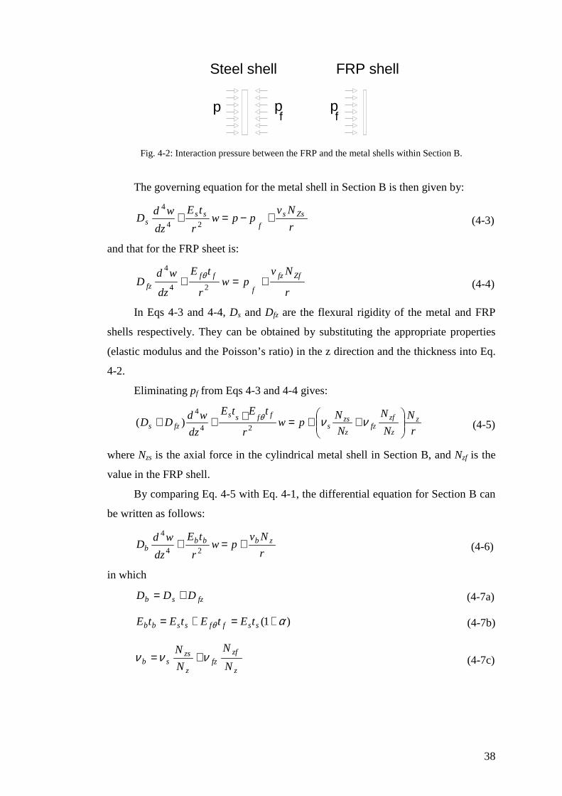
38
Steel shell FRP shell
p pf f
p
Fig. 4-2: Interaction pressure between the FRP and the metal shells within Section B.
The governing equation for the metal shell in Section B is then given by:
r
Nvppw
r
tE
dz
wdD Zss
f
sss +−=+
24
4
(4-3)
and that for the FRP sheet is:
r
Nvpw
r
tE
dz
wdD
Zffz
f
fffz +=+
24
4θ
(4-4)
In Eqs 4-3 and 4-4, Ds and Dfz are the flexural rigidity of the metal and FRP
shells respectively. They can be obtained by substituting the appropriate properties
(elastic modulus and the Poisson’s ratio) in the z direction and the thickness into Eq.
4-2.
Eliminating pf from Eqs 4-3 and 4-4 gives:
r
N
N
N
N
Npw
r
tEtE
dz
wdDD z
z
zffz
z
zss
ffss
fzs
++=+++ ννθ
24
4
)( (4-5)
where Nzs is the axial force in the cylindrical metal shell in Section B, and Nzf is the
value in the FRP shell.
By comparing Eq. 4-5 with Eq. 4-1, the differential equation for Section B can
be written as follows:
r
Nvpw
r
tE
dz
wdD zbbb
b +=+24
4
(4-6)
in which
fzsb DDD += (4-7a)
)1( αθ +=+= ssffssbb tEtEtEtE (4-7b)
z
zffz
z
zssb N
N
N
Nννν += (4-7c)
39
in which the extensional stiffness ratio of FRP to the steel shell is represented by:
ss
ff
tE
tE θα = (4-8)
Section B may be treated as an equivalent metal shell. The effective thickness
tb of the converted Section B may be derived by equating the ratio of the flexural to
the extensional stiffness of the equivalent shell to that of the metal-FRP composite
shell as:
bb
b
bb
bb
b
tE
tE
tE
D )1(12 2
3
ν−= (4-9)
Substituting Eqs 4-7a and 4-7b into the left hand side of Eq. 4-9 and
rearranging the resulting equation gives:
θB
Dt bb
12= (4-10)
where Bθ is the extensional stiffness in circumferential direction for Section B:
22 1
)1(
1 b
ss
b
bb tEtEB
να
νθ−
+=
−= (4-11)
The same expression for bt can also be found in Baker et al. (1986) for an
equivalent homogeneous isotropic cylinder, having the same stiffness properties as
the composite orthotropic cylinder.
If the FRP fibres are applied in the circumferential direction, then Young’s
modulus of FRP in the meridional direction is very small compared with that in the
circumferential direction and that of the metal shell. In addition, it is anticipated that
only thin FRP sheets would be required to achieve the strengthening purpose.
Therefore, both the flexural and extensional rigidities of the FRP in the meridional
direction would be much smaller than those of the metal shell and can be neglected
(Teng and Hu, 2004, 2007). In such a case, Eq. 4-5 may be rewritten by ignoring the
terms relating to the meridional direction properties of FRP:
r
Npw
r
tE
dz
wdD z
sss
s να
+=+
+24
4 )1( (4-12)
40
Similarly, the properties for an equivalent metal shell for Section B can be
obtained from Eqs 4-7 and 4-10 as:
)1(12 2
3
s
sssb
tEDD
ν−== (4-13a)
sb νν = (4-13b)
and )1(
)1(12 2
αν
+−=ss
ssb tE
Dt (4-13c)
4.2.3 General solution
The general solution of Eq. 4-1 (Rotter, 1985b) is:
mzz we
zC
zCe
zC
zCw }1]sincos[]sincos{[ /
43/
21 ++++= − λπλπ
λπ
λπ
λπ
λπ
(4-14)
in which λ is the meridional bending half-wavelength given by Eq. 2-3 and wm is the
membrane theory normal deflection:
ss
zsm tE
r
r
Nvpw
2
)( += (4-15)
For Section B, the meridional bending half-wavelength, λb, and the membrane
theory normal deflection, wmb, can be obtained as follows:
( )[ ] b
s
b rtv
4/1213 −= πλ (4-16a)
)1(
2
αν
++=
ss
zsmb
tE
r
r
Npw (4-16b)
The stress resultants in the shell may be expressed in terms of displacements as:
zvNwR
EtN +=θ (4-17a)
2
2
dz
wdDM z −= (4-17b)
zvMM =θ (4-17c)
41
3
3
dz
wdDQz −= (4-17d)
Shell Section A
It is assumed that Section A of the metal cylindrical shell is long, so that the
upper end boundary condition is not important. Writing:
λπ
λπ )( ffa
a
hxzzx
−−== (4-18)
and from Eq. 4-14:
( ) max
aaaawexCxCw
++= −1sincos
21 (4-19a)
differentiation gives the meridional slope, curvature and third derivative as:
a
aaa
aaam
a
xexxC
xxCw
dz
dw −
−+
+−==
)sin(cos
)cos(sin.
2
1
λπβ (4-19b)
[ ] axaaaam
a
exCxCwdz
wd −−
= cossin221
2
2
2
λπ
(4-19c)
[ ] axaaaaaam
a
exxCxxCwdz
wd −+++−
= )sin(cos)cossin(221
3
3
3
λπ
(4-19d)
The deformation and internal forces at the junction between the shell Sections
A and B (za=0 in Fig. 4-1) can be found from Eqs 4-17 and 4-19.
( ) maa wCw 11 += (4-20a)
][ 21 aama CCw +−=λπβ (4-20b)
2
2
2 amsa CwDM
=λπ
(4-20c)
[ ]21
3
2aamsa CCwDQ +
−=λπ
(4-20d)
Shell Section B
Section B is a composite shell with different properties, as described earlier. It
must be treated as a short shell since its two ends may be relatively close to each
other.
42
b
f
b
bb
xzzx
λλπ )( −
== (4-21)
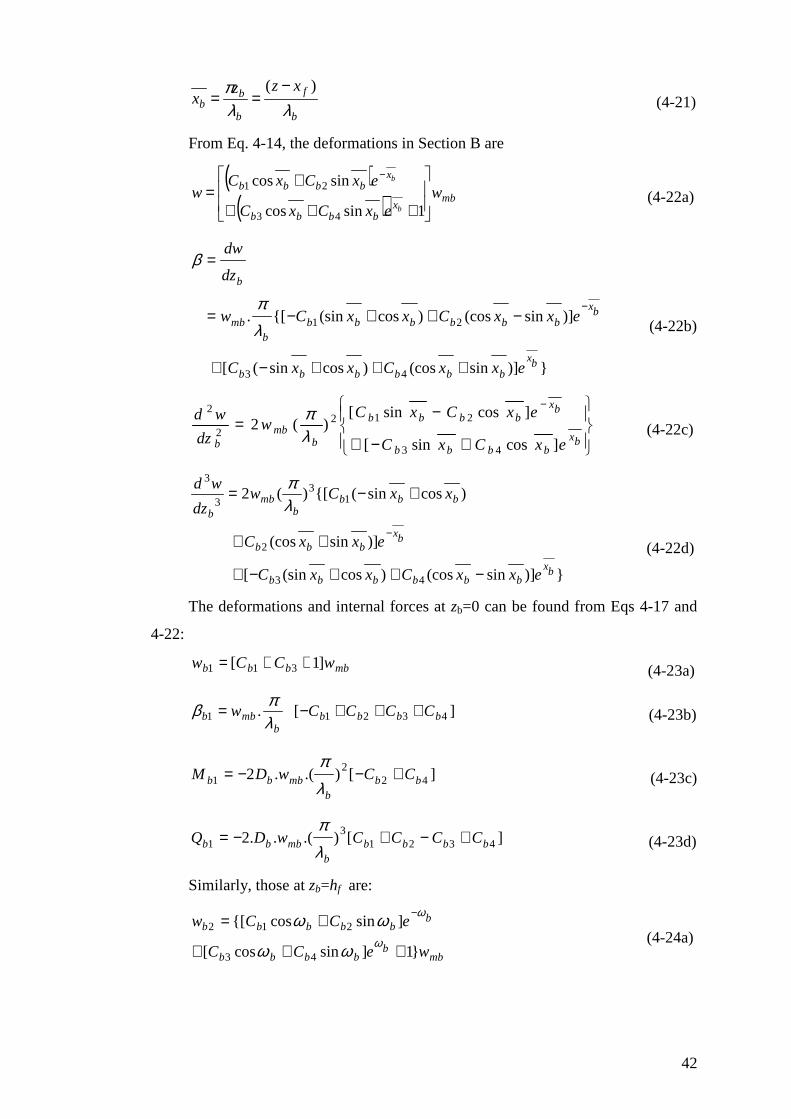
From Eq. 4-14, the deformations in Section B are
( )( ) mb
xbbbb
xbbbb w
exCxC
exCxCw
b
b
+++
+=
−
1sincos
sincos
43
21 (4-22a)
})]sin(cos)cossin([
)]sin(cos)cos(sin{[.
43
21
bx
bbbbbb
bx
bbbbbbb
mb
b
exxCxxC
exxCxxCw
dz
dw
+++−+
−++−=
=
−
λπ
β
(4-22b)
+−+
−=
−
bxbbbb
bxbbbb
bmb
b exCxC
exCxCw
dz
wd
]cossin[
]cossin[)(2
43
2122
2
λπ
(4-22c)
})]sin(cos)cos(sin[
)]sin(cos
)cossin({[)(2
43
2
13
3
3
bxbbbbbb
bxbbb
bbbb
mbb
exxCxxC
exxC
xxCwdz
wd
−++−+
++
+−=
−
λπ
(4-22d)
The deformations and internal forces at zb=0 can be found from Eqs 4-17 and
4-22:
mbbbb wCCw ]1[ 311 ++= (4-23a)
][. 43211 bbbbb
mbb CCCCw +++−=λπβ (4-23b)
][).(.2 422
1 bbb
mbbb CCwDM +−−=λπ
(4-23c)
][).(..2 43213
1 bbbbb
mbbb CCCCwDQ +−+−=λπ
(4-23d)
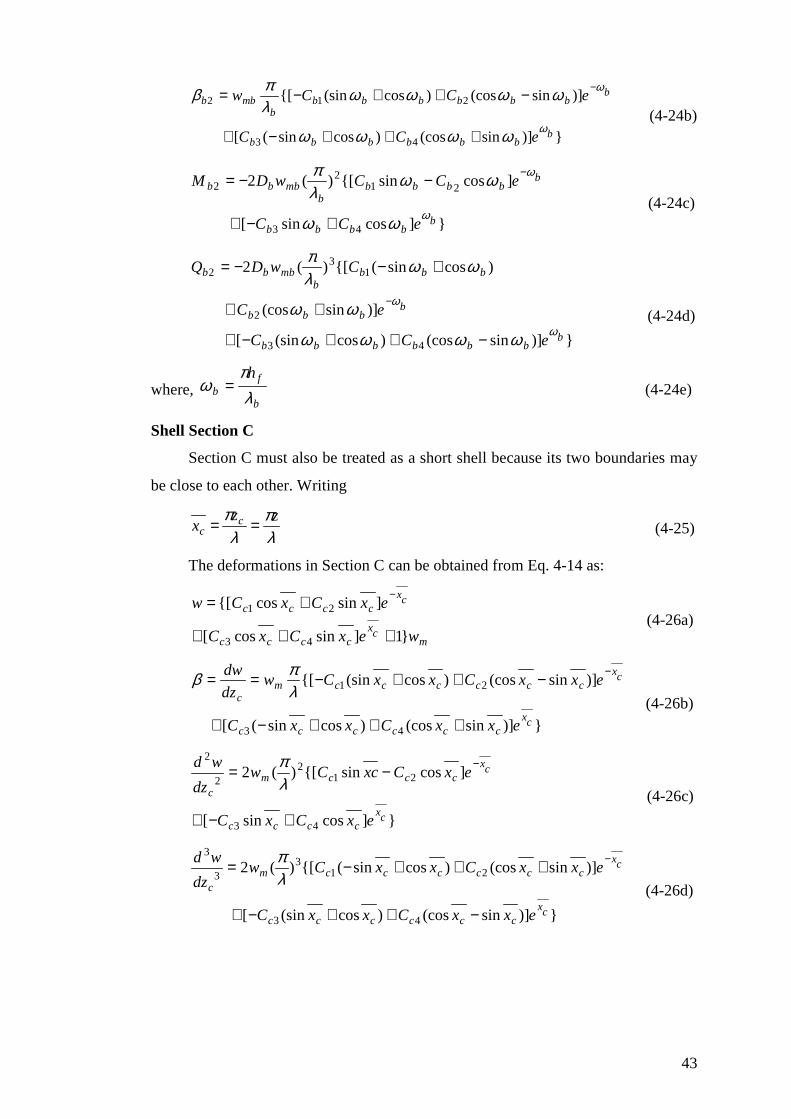
Similarly, those at zb=hf are:
mbb
bbbb
bbbbbb
weCC
eCCw
}1]sincos[
]sincos{[
43
212
+++
+= −
ϖ
ϖ
ϖϖ
ϖϖ (4-24a)
43
})]sin(cos)cossin([
)]sin(cos)cos(sin{[
43
212
bbbbbbb
bbbbbbb
bmbb
eCC
eCCw
ϖ
ϖ
ϖϖϖϖ
ϖϖϖϖλπβ
+++−+
−++−= −
(4-24b)
}]cossin[
]cossin{[)(2
43
212
2
bbbbb
bbbbb
bmbbb
eCC
eCCwDM
ϖ
ϖ
ϖϖ
ϖϖλπ
+−+
−−= −
(4-24c)
})]sin(cos)cos(sin[
)]sin(cos
)cossin({[)(2
43
2
13
2
bbbbbbb
bbbb
bbbb
mbbb
eCC
eC
CwDQ
ϖ
ϖ
ϖϖϖϖ
ϖϖ
ϖϖλπ
−++−+
++
+−−=
− (4-24d)
where, b
fb
h
λπ
ϖ = (4-24e)
Shell Section C
Section C must also be treated as a short shell because its two boundaries may
be close to each other. Writing
λπ
λπ zz
x cc == (4-25)
The deformations in Section C can be obtained from Eq. 4-14 as:
mcx
cccc
cxcccc
wexCxC
exCxCw
}1]sincos[
]sincos{[
43
21
+++
+= −
(4-26a)
})]sin(cos)cossin([
)]sin(cos)cos(sin{[
43
21
cxcccccc
cxccccccm
c
exxCxxC
exxCxxCwdz
dw
+++−+
−++−== −
λπβ
(4-26b)
}]cossin[
]cossin{[)(2
43
212
2
2
cxcccc
cxcccm
c
exCxC
exCxcCwdz
wd
+−+
−= −
λπ
(4-26c)
})]sin(cos)cos(sin[
)]sin(cos)cossin({[)(2
43
213
3
3
cxcccccc
cxccccccm
c
exxCxxC
exxCxxCwdz
wd
−++−+
+++−= −
λπ
(4-26d)
44
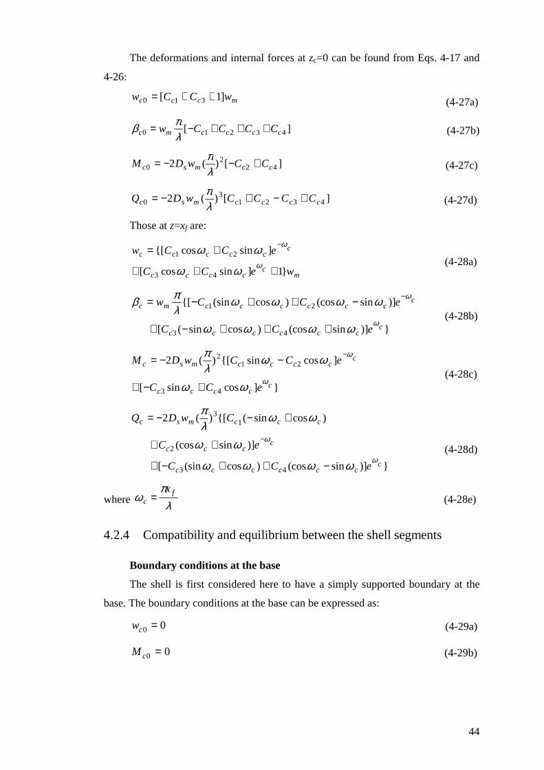
The deformations and internal forces at zc=0 can be found from Eqs. 4-17 and
4-26:
mccc wCCw ]1[ 310 ++= (4-27a)
][ 43210 ccccmc CCCCw +++−=λπβ (4-27b)
][)(2 422
0 ccmsc CCwDM +−−=λπ
(4-27c)
][)(2 43213
0 ccccmsc CCCCwDQ +−+−=λπ
(4-27d)
Those at z=xf are:
mc
cccc
cccccc
weCC
eCCw
}1]sincos[
]sincos{[
43
21
+++
+= −
ϖ
ϖ
ϖϖ
ϖϖ (4-28a)
})]sin(cos)cossin([
)]sin(cos)cos(sin{[
43
21
ccccccc
cccccccmc
eCC
eCCw
ϖ
ϖ
ϖϖϖϖ
ϖϖϖϖλπβ
+++−+
−++−= −
(4-28b)
}]cossin[
]cossin{[)(2
43
212
ccccc
cccccmsc
eCC
eCCwDM
ϖ
ϖ
ϖϖ
ϖϖλπ
+−+
−−= −
(4-28c)
})]sin(cos)cos(sin[
)]sin(cos
)cossin({[)(2
43
2
13
ccccccc
cccc
cccmsc
eCC
eC
CwDQ
ϖ
ϖ
ϖϖϖϖ
ϖϖ
ϖϖλπ
−++−+
++
+−−=
− (4-28d)
where λπ
ϖ fc
x= (4-28e)
4.2.4 Compatibility and equilibrium between the shell segments
Boundary conditions at the base
The shell is first considered here to have a simply supported boundary at the
base. The boundary conditions at the base can be expressed as:
00 =cw (4-29a)
00 =cM (4-29b)

45
Substituting Eqs 4-27 into 4-29 gives:
)1( 13 +−= cc CC (4-30)
24 cc CC = (4-31)
Continuity at Joint 1
The condition for deformation continuity at Joint 1 requires that
1bc ww = (4-32a)
1bc ββ = (4-32b)
Substituting Eqs 4-28a and 4-28b into Eqs 4-23a and 4-23b respectively gives:
01)(sin
)(cos)(sin)(cos
314
321
=−+−−+
++ −−
m
mb
m
mbb
m
mbb
ccc
ccc
ccc
ccc
w
w
w
wC
w
wCeC
eCeCeC
ϖ
ϖϖϖ
ϖ
ϖϖϖ (4-33)
0....])sin[(cos
])cossin[(
])sin[(cos])cos(sin[
141312114
3
21
=−−−+++
+−+
−++− −−
FCFCFCFCeC
eC
eCeC
bbbbc
ccc
cccc
cccc
cccc
ϖ
ϖ
ϖϖ
ϖϖ
ϖϖ
ϖϖϖϖ
(4-34)
in which,bm
mb
w
wF
λλ
.1 = (4-35)
Equilibrium at Joint 1
Equilibrium at Joint 1 requires that:
1bc MM = (4-36a)
1bc QQ = (4-36b)
Substituting Eqs 4-28c and 4-28d into Eqs 4-23c and 4-23d respectively gives:
0
cossincossin
2422
4321
=−+
+−−−−
FCFC
eCeCeCeC
bb
ccc
ccc
ccc
ccc
ϖϖϖϖϖϖϖϖ
(4-37)
0])sin[(cos
])cos(sin[
])sin[(cos])cossin[(
343332134
3
21
=−+−−−+
+−+
+++− −−
FCFCFCCFeC
eC
eCeC
bbbbc
ccc
cccc
cccc
cccc
ϖ
ϖ
ϖϖ
ϖϖ
ϖϖ
ϖϖϖϖ
(4-38)
where, D
D
w
wF b
bm
mb2
2
2 λλ= (4-39)

46
and, D
D
w
wF b
bm
mb3
3
3 λλ= (4-40)
Continuity at Joint 2
Continuity at Joint 2 requires
2ba ww = (4-41a)
2ba ββ = (4-41b)
Substituting Eqs 4-20a and 4-20b into Eqs 4-24a and 4-24b respectively gives:
01)()(sin
)(cos)(sin)(cos
14
321
=−+−++
++ −−
mb
m
mb
ma
bbb
bbb
bbb
bbb
w
w
w
wCeC
eCeCeC
ϖ
ϖϖϖ
ϖ
ϖϖϖ (4-42)
0)1
()1
(
])sin[(cos])cossin[(
])sin[(cos])cos(sin[
12
11
43
21
=−++
+++−+
−++− −−
FC
FC
eCeC
eCeC
aa
bbbb
bbbb
bbbb
bbbb
ϖϖ
ϖϖ
ϖϖϖϖ
ϖϖϖϖ
(4-43)
Equilibrium at Joint 2
The equilibrium at Joint 2 requires that
2ba MM = (4-44a)
2ba QQ = (4-44b)
Substituting Eqs 4-20c and 4-20d into Eqs 4-24c and 4-24d respectively gives:
0)1
()cos(
)(sin)(cos)sin(
224
321
=−+−+
++− −−
FCeC
eCeCeC
ab
bb
bbb
bbb
bbb
ϖ
ϖϖϖ
ϖ
ϖϖϖ (4-45)
0)1
()1
(
])sin[(cos])cos(sin[
])sin[(cos])cossin[(
32
31
43
21
=−+−+
−++−+
+++− −−
FC
FC
eCeC
eCeC
aa
bbbb
bbbb
bbbb
bbbb
ϖϖ
ϖϖ
ϖϖϖϖ
ϖϖϖϖ
(4-46)
Substituting Eqs 4-30 and 4-31 into Eqs 4-33 to 4-46 and rearranging the
resulting equations in matrix form gives
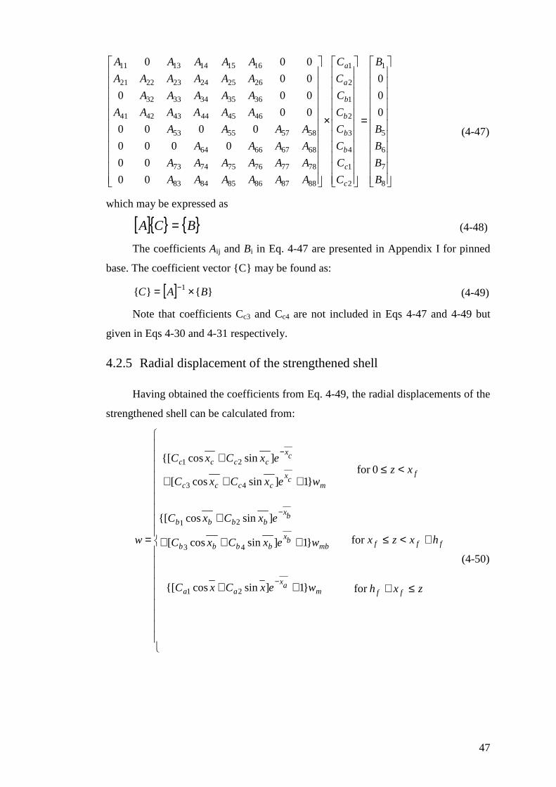
47
=
×
8
7
6
5
1
2
1
4
3
2
1
2
1
888786858483
787776757473
68676664
58575553
464544434241
3635343332
262524232221
1615141311
0
0
0
00
00
0000
0000
00
000
00
000
B
B
B
B
B
C
C
C
C
C
C
C
C
AAAAAA
AAAAAA
AAAA
AAAA
AAAAAA
AAAAA
AAAAAA
AAAAA
c
c
b
b
b
b
a
a
(4-47)
which may be expressed as
[ ]{ } { }BCA = (4-48)
The coefficients Aij and Bi in Eq. 4-47 are presented in Appendix I for pinned
base. The coefficient vector {C} may be found as:
[ ] }{}{ 1 BAC ×= − (4-49)
Note that coefficients Cc3 and Cc4 are not included in Eqs 4-47 and 4-49 but
given in Eqs 4-30 and 4-31 respectively.
4.2.5 Radial displacement of the strengthened shell
Having obtained the coefficients from Eq. 4-49, the radial displacements of the
strengthened shell can be calculated from:
≤+
+<≤
<≤
++
+++
+
+++
+
=
−
−
−
zxh
hxzx
xz
wexCxC
wexCxC
exCxC
wexCxC
exCxC
w
ff
fff
f
max
aa
mbbx
bbbb
bxbbbb
mcx
cccc
cxcccc
for
for
0for
}1]sincos{[
}1]sincos[
]sincos{[
}1]sincos[
]sincos{[
21
43
21
43
21
(4-50)
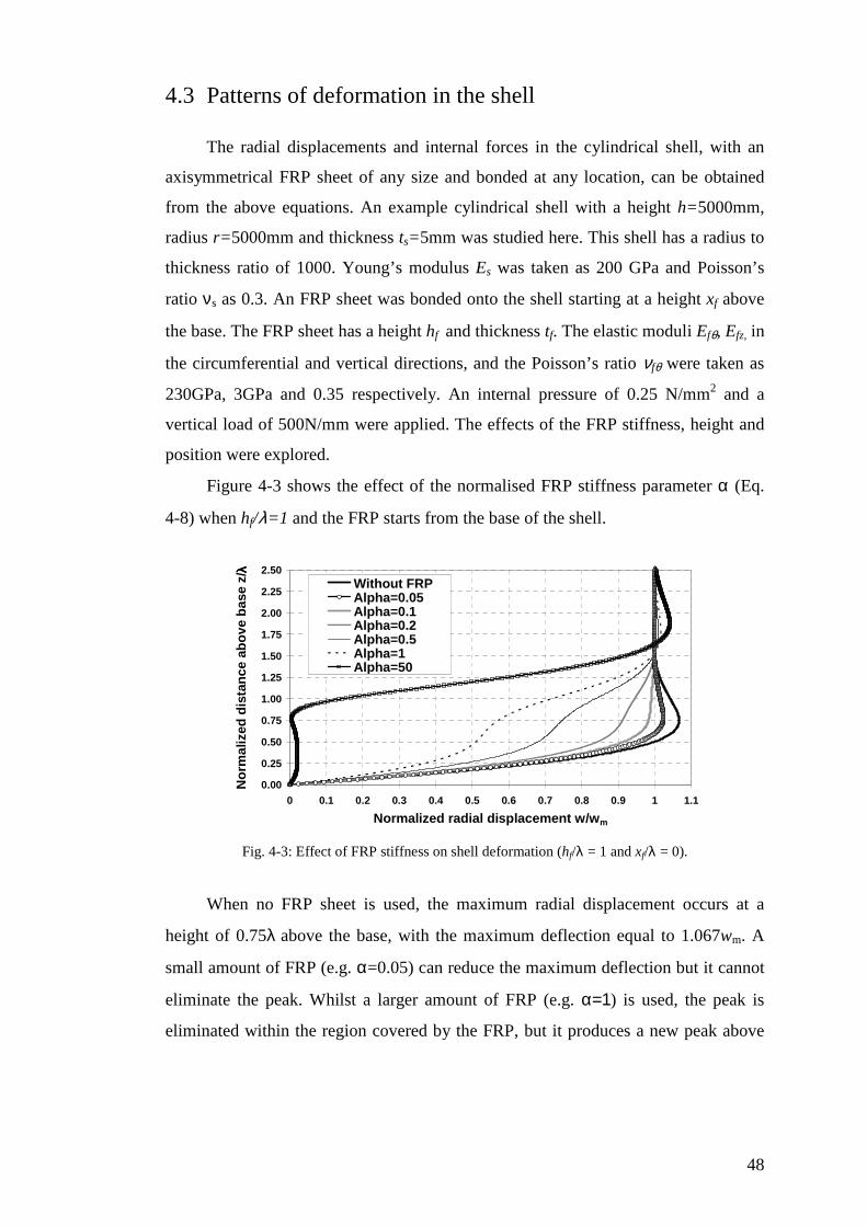
48
4.3 Patterns of deformation in the shell
The radial displacements and internal forces in the cylindrical shell, with an
axisymmetrical FRP sheet of any size and bonded at any location, can be obtained
from the above equations. An example cylindrical shell with a height h=5000mm,
radius r= 5000mm and thickness ts=5mm was studied here. This shell has a radius to
thickness ratio of 1000. Young’s modulus Es was taken as 200 GPa and Poisson’s
ratio νs as 0.3. An FRP sheet was bonded onto the shell starting at a height xf above
the base. The FRP sheet has a height hf and thickness tf. The elastic moduli Efθ, Efz, in
the circumferential and vertical directions, and the Poisson’s ratio νfθ were taken as
230GPa, 3GPa and 0.35 respectively. An internal pressure of 0.25 N/mm2 and a
vertical load of 500N/mm were applied. The effects of the FRP stiffness, height and
position were explored.
Figure 4-3 shows the effect of the normalised FRP stiffness parameter α (Eq.
4-8) when hf/λ=1 and the FRP starts from the base of the shell.
0.00
0.25
0.50
0.75
1.00
1.25
1.50
1.75
2.00
2.25
2.50
0 0.1 0.2 0.3 0.4 0.5 0.6 0.7 0.8 0.9 1 1.1
Normalized radial displacement w/wm
No
rmal
ized
dis
tan
ce a
bo
ve b
ase
z/λλ λλ
Without FRPAlpha=0.05Alpha=0.1Alpha=0.2Alpha=0.5Alpha=1Alpha=50
Fig. 4-3: Effect of FRP stiffness on shell deformation (hf/λ = 1 and xf/λ = 0).
When no FRP sheet is used, the maximum radial displacement occurs at a
height of 0.75λ above the base, with the maximum deflection equal to 1.067wm. A
small amount of FRP (e.g. α=0.05) can reduce the maximum deflection but it cannot
eliminate the peak. Whilst a larger amount of FRP (e.g. α=1) is used, the peak is
eliminated within the region covered by the FRP, but it produces a new peak above
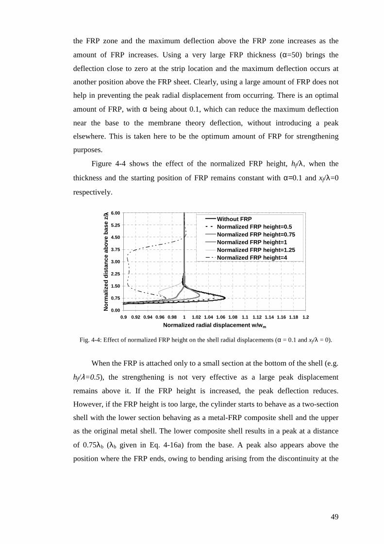
49
the FRP zone and the maximum deflection above the FRP zone increases as the
amount of FRP increases. Using a very large FRP thickness (α=50) brings the
deflection close to zero at the strip location and the maximum deflection occurs at
another position above the FRP sheet. Clearly, using a large amount of FRP does not
help in preventing the peak radial displacement from occurring. There is an optimal
amount of FRP, with α being about 0.1, which can reduce the maximum deflection
near the base to the membrane theory deflection, without introducing a peak
elsewhere. This is taken here to be the optimum amount of FRP for strengthening
purposes.
Figure 4-4 shows the effect of the normalized FRP height, hf/λ, when the
thickness and the starting position of FRP remains constant with α=0.1 and xf/λ=0
respectively.
0.00
0.75
1.50
2.25
3.00
3.75
4.50
5.25
6.00
0.9 0.92 0.94 0.96 0.98 1 1.02 1.04 1.06 1.08 1.1 1.12 1.14 1.16 1.18 1.2
Normalized radial displacement w/wm
No
rmal
ized
dis
tan
ce a
bo
ve b
ase
z/λλ λλ
Without FRPNormalized FRP height=0.5Normalized FRP height=0.75Normalized FRP height=1Normalized FRP height=1.25Normalized FRP height=4
Fig. 4-4: Effect of normalized FRP height on the shell radial displacements (α = 0.1 and xf/λ = 0).
When the FRP is attached only to a small section at the bottom of the shell (e.g.
hf/λ=0.5), the strengthening is not very effective as a large peak displacement
remains above it. If the FRP height is increased, the peak deflection reduces.
However, if the FRP height is too large, the cylinder starts to behave as a two-section
shell with the lower section behaving as a metal-FRP composite shell and the upper
as the original metal shell. The lower composite shell results in a peak at a distance
of 0.75λb (λb given in Eq. 4-16a) from the base. A peak also appears above the
position where the FRP ends, owing to bending arising from the discontinuity at the
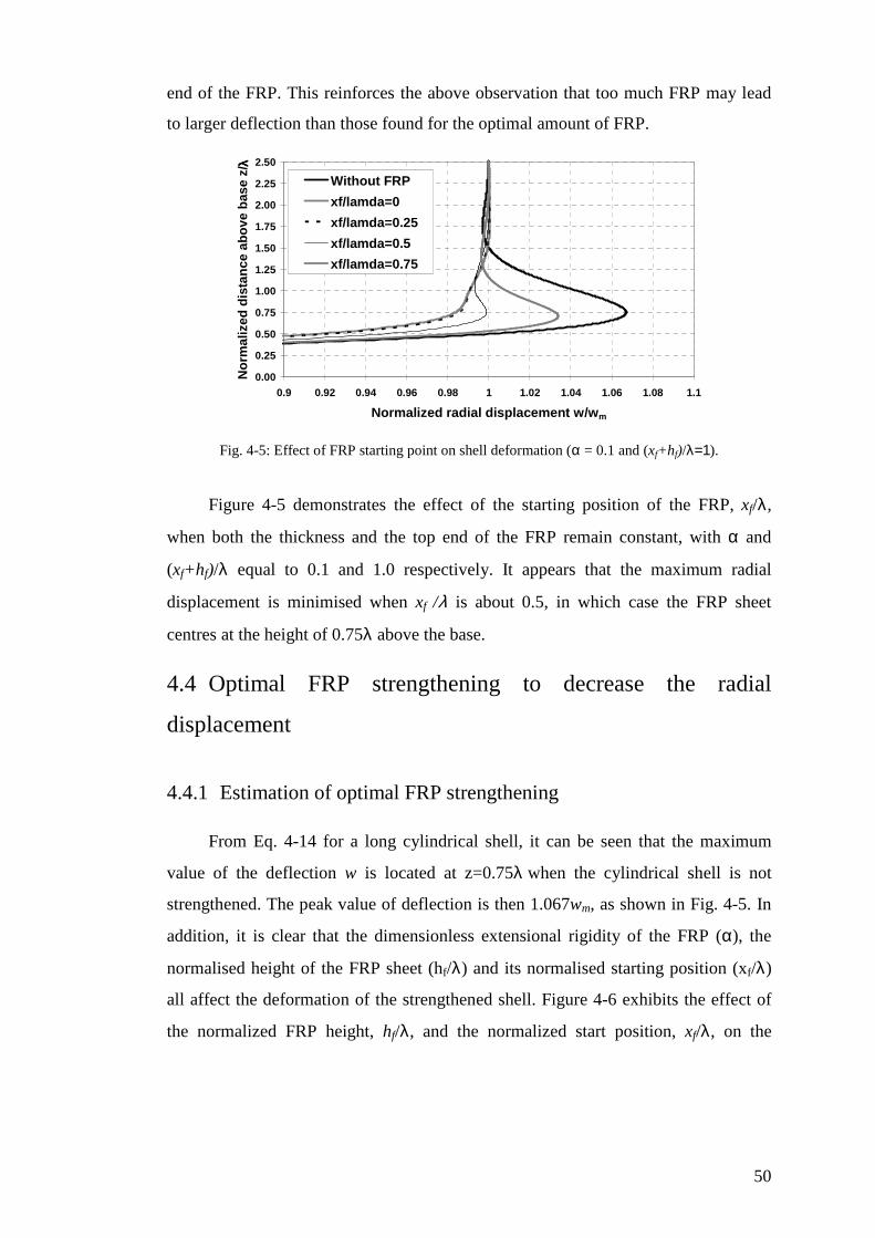
50
end of the FRP. This reinforces the above observation that too much FRP may lead
to larger deflection than those found for the optimal amount of FRP.
0.00
0.25
0.50
0.75
1.00
1.25
1.50
1.75
2.00
2.25
2.50
0.9 0.92 0.94 0.96 0.98 1 1.02 1.04 1.06 1.08 1.1
Normalized radial displacement w/wm
No
rmal
ized
dis
tan
ce a
bo
ve b
ase
z/λλ λλ
Without FRP
xf/lamda=0
xf/lamda=0.25
xf/lamda=0.5
xf/lamda=0.75
Fig. 4-5: Effect of FRP starting point on shell deformation (α = 0.1 and (xf+hf)/λ=1).
Figure 4-5 demonstrates the effect of the starting position of the FRP, xf/λ,
when both the thickness and the top end of the FRP remain constant, with α and
(xf+hf)/λ equal to 0.1 and 1.0 respectively. It appears that the maximum radial
displacement is minimised when xf /λ is about 0.5, in which case the FRP sheet
centres at the height of 0.75λ above the base.
4.4 Optimal FRP strengthening to decrease the radial
displacement
4.4.1 Estimation of optimal FRP strengthening
From Eq. 4-14 for a long cylindrical shell, it can be seen that the maximum
value of the deflection w is located at z=0.75λ when the cylindrical shell is not
strengthened. The peak value of deflection is then 1.067wm, as shown in Fig. 4-5. In
addition, it is clear that the dimensionless extensional rigidity of the FRP (α), the
normalised height of the FRP sheet (hf/λ) and its normalised starting position (xf/λ)
all affect the deformation of the strengthened shell. Figure 4-6 exhibits the effect of
the normalized FRP height, hf/λ, and the normalized start position, xf/λ, on the
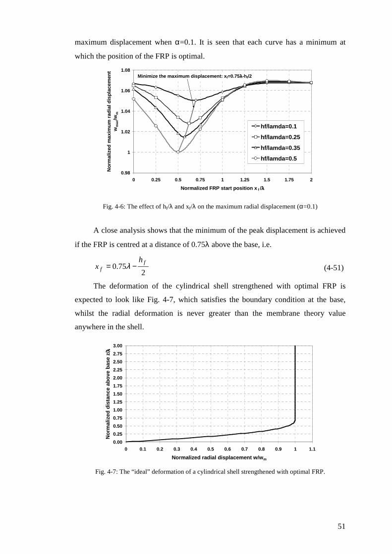
51
maximum displacement when α=0.1. It is seen that each curve has a minimum at
which the position of the FRP is optimal.
0.98
1
1.02
1.04
1.06
1.08
0 0.25 0.5 0.75 1 1.25 1.5 1.75 2
Normalized FRP start position x f /λλλλ
No
rmal
ized
max
imu
m r
adia
l dis
pla
cem
ent
wm
ax/w
m
hf/lamda=0.1
hf/lamda=0.25
hf/lamda=0.35
hf/lamda=0.5
Minimize the maximum displacement: xf=0.75λλλλ-hf/2
Fig. 4-6: The effect of hf/λ and xf/λ on the maximum radial displacement (α=0.1)
A close analysis shows that the minimum of the peak displacement is achieved
if the FRP is centred at a distance of 0.75λ above the base, i.e.
275.0
ff
hx −= λ (4-51)
The deformation of the cylindrical shell strengthened with optimal FRP is
expected to look like Fig. 4-7, which satisfies the boundary condition at the base,
whilst the radial deformation is never greater than the membrane theory value
anywhere in the shell.
0.00
0.25
0.50
0.75
1.00
1.25
1.50
1.75
2.00
2.25
2.50
2.75
3.00
0 0.1 0.2 0.3 0.4 0.5 0.6 0.7 0.8 0.9 1 1.1
Normalized radial displacement w/wm
No
rmal
ized
dis
tan
ce a
bo
ve b
ase
z/λλ λλ
Fig. 4-7: The “ideal” deformation of a cylindrical shell strengthened with optimal FRP.
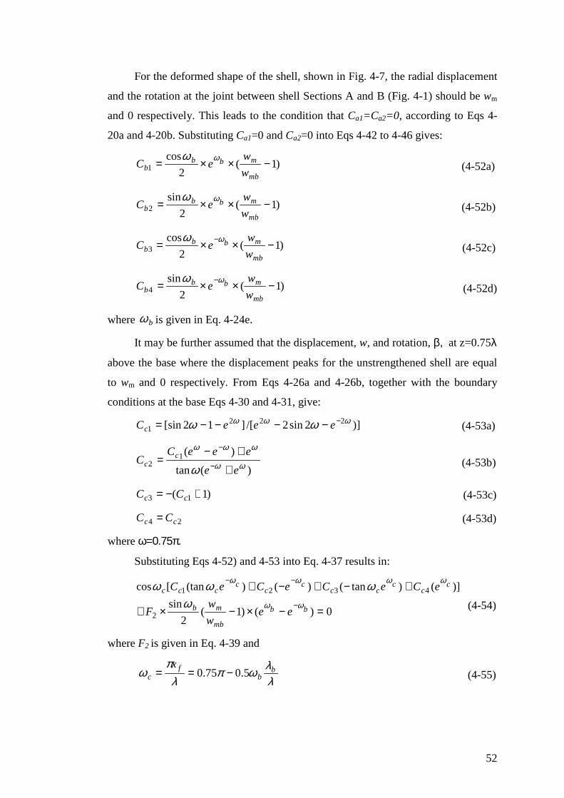
52
For the deformed shape of the shell, shown in Fig. 4-7, the radial displacement
and the rotation at the joint between shell Sections A and B (Fig. 4-1) should be wm
and 0 respectively. This leads to the condition that Ca1=Ca2=0, according to Eqs 4-
20a and 4-20b. Substituting Ca1=0 and Ca2=0 into Eqs 4-42 to 4-46 gives:
)1(2
cos1 −××=
mb
mbbb w
weC
ϖϖ (4-52a)
)1(2
sin2 −××=
mb
mbbb w
weC
ϖϖ (4-52b)
)1(2
cos3 −××= −
mb
mbbb w
weC
ϖϖ (4-52c)
)1(2
sin4 −××= −
mb
mbbb w
weC
ϖϖ (4-52d)
where bϖ is given in Eq. 4-24e.
It may be further assumed that the displacement, w, and rotation, β, at z=0.75λ
above the base where the displacement peaks for the unstrengthened shell are equal
to wm and 0 respectively. From Eqs 4-26a and 4-26b, together with the boundary
conditions at the base Eqs 4-30 and 4-31, give:
)]2sin2/[]12[sin 2221
ϖϖϖ ϖϖ −−−−−= eeeCc (4-53a)
)(tan
)(12 ϖϖ
ϖϖϖ
ϖ ee
eeeCC c
c +
+−= −
−
(4-53b)
)1( 13 +−= cc CC (4-53c)
24 cc CC = (4-53d)
where ϖ=0.75π.
Substituting Eqs 4-52) and 4-53 into Eq. 4-37 results in:
0)()1(2
sin
)]()tan()()(tan[cos
2
4321
=−×−×+
+−+−+−
−−
bb
mb
mb
cc
ccc
cc
cccc
eew
wF
eCeCeCeC
ϖϖ
ϖϖϖϖ
ϖϖϖϖ
(4-54)
where F2 is given in Eq. 4-39 and
λλϖπ
λπ
ϖ bb
fc
x5.075.0 −== (4-55)
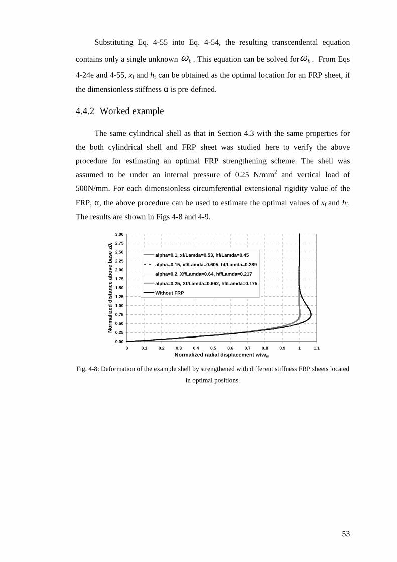
53
Substituting Eq. 4-55 into Eq. 4-54, the resulting transcendental equation
contains only a single unknown bϖ . This equation can be solved forbϖ . From Eqs
4-24e and 4-55, xf and hf can be obtained as the optimal location for an FRP sheet, if
the dimensionless stiffness α is pre-defined.
4.4.2 Worked example
The same cylindrical shell as that in Section 4.3 with the same properties for
the both cylindrical shell and FRP sheet was studied here to verify the above
procedure for estimating an optimal FRP strengthening scheme. The shell was
assumed to be under an internal pressure of 0.25 N/mm2 and vertical load of
500N/mm. For each dimensionless circumferential extensional rigidity value of the
FRP, α, the above procedure can be used to estimate the optimal values of xf and hf.
The results are shown in Figs 4-8 and 4-9.
0.00
0.25
0.50
0.75
1.00
1.25
1.50
1.75
2.00
2.25
2.50
2.75
3.00
0 0.1 0.2 0.3 0.4 0.5 0.6 0.7 0.8 0.9 1 1.1
Normalized radial displacement w/wm
No
rmal
ized
dis
tan
ce a
bo
ve b
ase
z/λλ λλ
alpha=0.1, xf/Lamda=0.53, hf/Lamda=0.45
alpha=0.15, xf/Lamda=0.605, hf/Lamda=0.289
alpha=0.2, Xf/Lamda=0.64, hf/Lamda=0.217
alpha=0.25, Xf/Lamda=0.662, hf/Lamda=0.175
Without FRP
Fig. 4-8: Deformation of the example shell by strengthened with different stiffness FRP sheets located
in optimal positions.
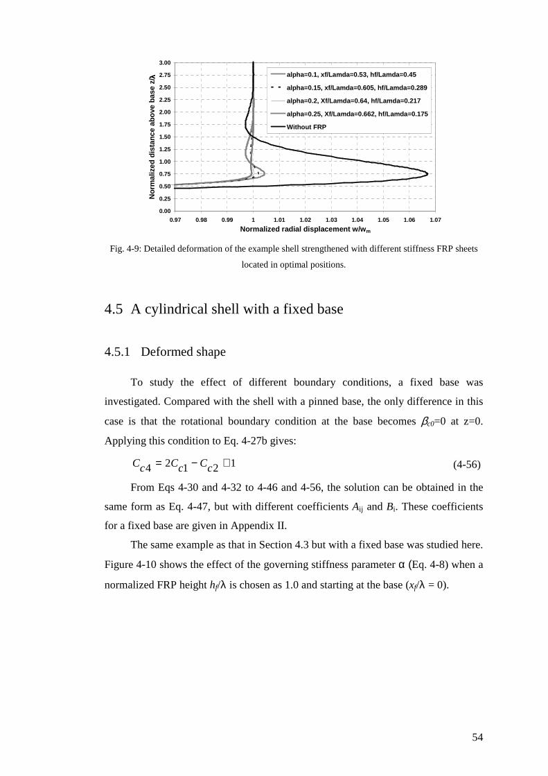
54
0.00
0.25
0.50
0.75
1.00
1.25
1.50
1.75
2.00
2.25
2.50
2.75
3.00
0.97 0.98 0.99 1 1.01 1.02 1.03 1.04 1.05 1.06 1.07
Normalized radial displacement w/wm
No
rmal
ized
dis
tan
ce a
bo
ve b
ase
z/λλ λλ alpha=0.1, xf/Lamda=0.53, hf/Lamda=0.45
alpha=0.15, xf/Lamda=0.605, hf/Lamda=0.289
alpha=0.2, Xf/Lamda=0.64, hf/Lamda=0.217
alpha=0.25, Xf/Lamda=0.662, hf/Lamda=0.175
Without FRP
Fig. 4-9: Detailed deformation of the example shell strengthened with different stiffness FRP sheets
located in optimal positions.
4.5 A cylindrical shell with a fixed base
4.5.1 Deformed shape
To study the effect of different boundary conditions, a fixed base was
investigated. Compared with the shell with a pinned base, the only difference in this
case is that the rotational boundary condition at the base becomes βc0=0 at z=0.
Applying this condition to Eq. 4-27b gives:
12124 +−= cCcCcC (4-56)
From Eqs 4-30 and 4-32 to 4-46 and 4-56, the solution can be obtained in the
same form as Eq. 4-47, but with different coefficients Aij and Bi. These coefficients
for a fixed base are given in Appendix II.
The same example as that in Section 4.3 but with a fixed base was studied here.
Figure 4-10 shows the effect of the governing stiffness parameter α (Eq. 4-8) when a
normalized FRP height hf/λ is chosen as 1.0 and starting at the base (xf/λ = 0).
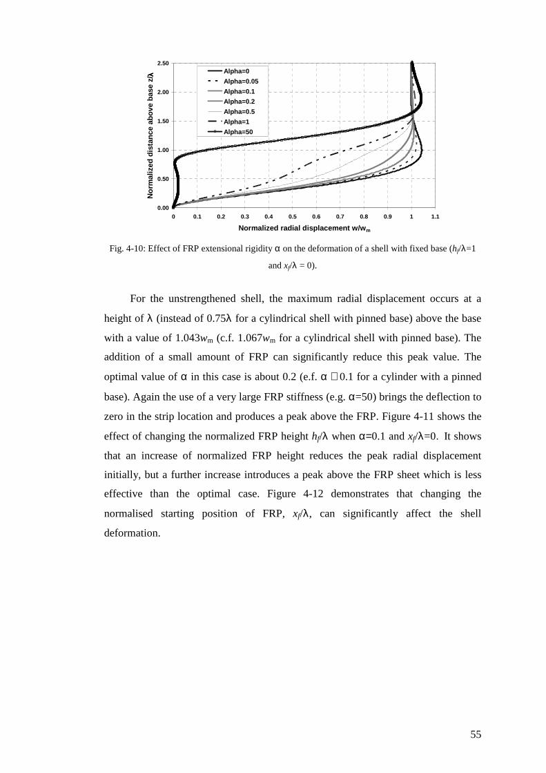
55
0.00
0.50
1.00
1.50
2.00
2.50
0 0.1 0.2 0.3 0.4 0.5 0.6 0.7 0.8 0.9 1 1.1
Normalized radial displacement w/wm
No
rmal
ized
dis
tan
ce a
bo
ve b
ase
z/λλ λλ Alpha=0
Alpha=0.05
Alpha=0.1
Alpha=0.2
Alpha=0.5
Alpha=1
Alpha=50
Fig. 4-10: Effect of FRP extensional rigidity α on the deformation of a shell with fixed base (hf/λ=1
and xf/λ = 0).
For the unstrengthened shell, the maximum radial displacement occurs at a
height of λ (instead of 0.75λ for a cylindrical shell with pinned base) above the base
with a value of 1.043wm (c.f. 1.067wm for a cylindrical shell with pinned base). The
addition of a small amount of FRP can significantly reduce this peak value. The
optimal value of α in this case is about 0.2 (e.f. α ≅ 0.1 for a cylinder with a pinned
base). Again the use of a very large FRP stiffness (e.g. α=50) brings the deflection to
zero in the strip location and produces a peak above the FRP. Figure 4-11 shows the
effect of changing the normalized FRP height hf/λ when α=0.1 and xf/λ=0. It shows
that an increase of normalized FRP height reduces the peak radial displacement
initially, but a further increase introduces a peak above the FRP sheet which is less
effective than the optimal case. Figure 4-12 demonstrates that changing the
normalised starting position of FRP, xf/λ, can significantly affect the shell
deformation.
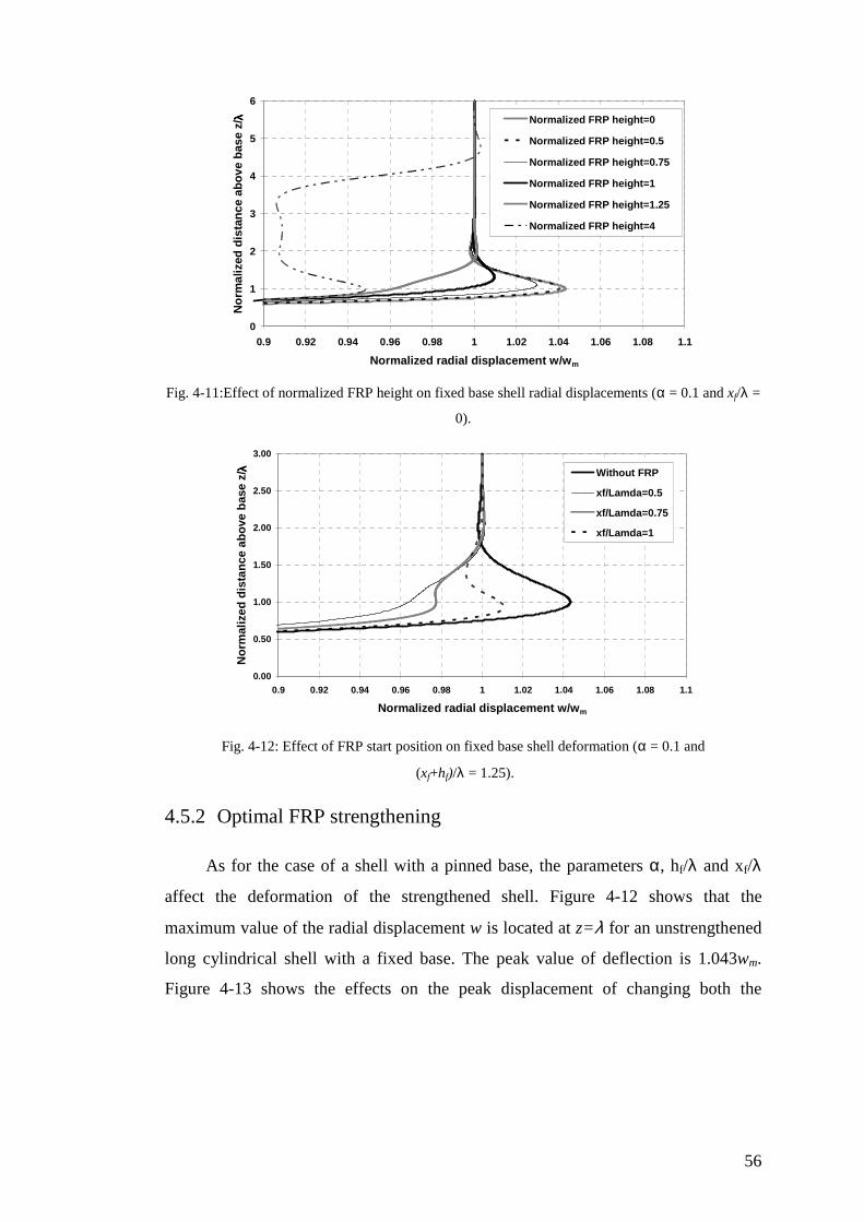
56
0
1
2
3
4
5
6
0.9 0.92 0.94 0.96 0.98 1 1.02 1.04 1.06 1.08 1.1
Normalized radial displacement w/wm
No
rmal
ized
dis
tan
ce a
bo
ve b
ase
z/λλ λλ Normalized FRP height=0
Normalized FRP height=0.5
Normalized FRP height=0.75
Normalized FRP height=1
Normalized FRP height=1.25
Normalized FRP height=4
Fig. 4-11:Effect of normalized FRP height on fixed base shell radial displacements (α = 0.1 and xf/λ =
0).
0.00
0.50
1.00
1.50
2.00
2.50
3.00
0.9 0.92 0.94 0.96 0.98 1 1.02 1.04 1.06 1.08 1.1
Normalized radial displacement w/wm
No
rmal
ized
dis
tan
ce a
bo
ve b
ase
z/λλ λλ Without FRP
xf/Lamda=0.5
xf/Lamda=0.75
xf/Lamda=1
Fig. 4-12: Effect of FRP start position on fixed base shell deformation (α = 0.1 and
(xf+hf)/λ = 1.25).
4.5.2 Optimal FRP strengthening
As for the case of a shell with a pinned base, the parameters α, hf/λ and xf/λ
affect the deformation of the strengthened shell. Figure 4-12 shows that the
maximum value of the radial displacement w is located at z=λ for an unstrengthened
long cylindrical shell with a fixed base. The peak value of deflection is 1.043wm.
Figure 4-13 shows the effects on the peak displacement of changing both the

57
normalized FRP height hf/λ and the normalized start position xf/λ. It is seen that the
optimal position for the FRP sheet is that it is centred at z = λ. That is:
2f
f
hx −= λ (4-57)
1
1.02
1.04
1.06
0 0.25 0.5 0.75 1 1.25 1.5 1.75 2
Normalized FRP start position x f /λλλλ
No
rmal
ized
max
imu
m r
adia
l dis
pla
cem
ent
wm
ax/w
m
hf/lamda=0.1
hf/lamda=0.15
hf/lamda=0.2
hf/lamda=0.25
Minimize the maximum displacement: xf=λλλλ-hf/2
Fig. 4-13: The effect of hf/λ and xf/λ on the maximum radial displacement for fixed base cylindrical
shell.
A similar procedure to that for a shell with a pinned base is developed here for
estimating the optimal FRP parameters, assuming that the deformation of the
strengthened shell with the optimal FRP is shown as in Fig. 4-14.
0.00
0.25
0.50
0.75
1.00
1.25
1.50
1.75
2.00
2.25
2.50
2.75
3.00
0 0.1 0.2 0.3 0.4 0.5 0.6 0.7 0.8 0.9 1 1.1
Normalized radial displacement w/wm
No
rmal
ized
dis
tan
ce a
bo
ve b
ase
z/λλ λλ
Fig. 4-14: The “ideal” deformation of a fixed base cylindrical shell strengthened with optimal FRP
strengthening.
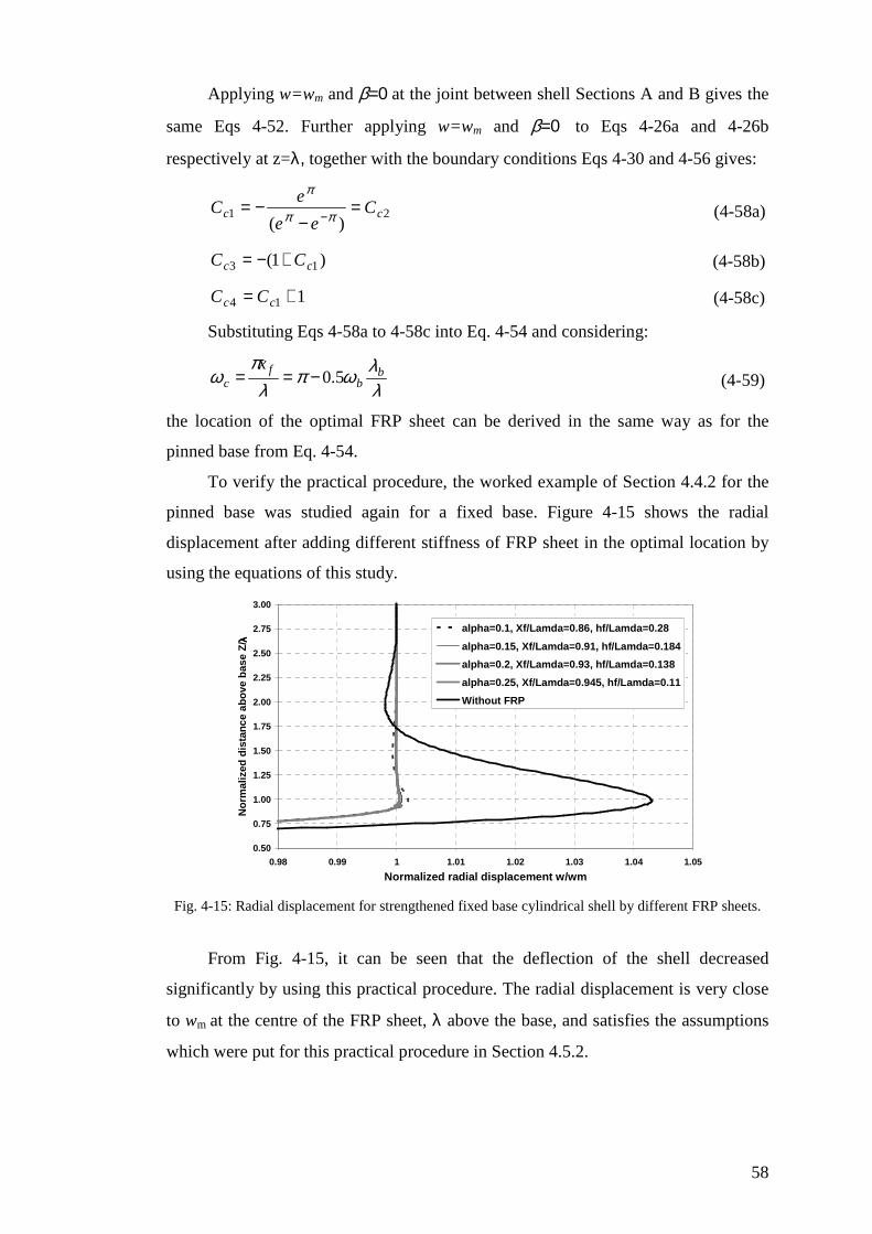
58
Applying w=wm and β=0 at the joint between shell Sections A and B gives the
same Eqs 4-52. Further applying w=wm and β=0 to Eqs 4-26a and 4-26b
respectively at z=λ, together with the boundary conditions Eqs 4-30 and 4-56 gives:
21)(
cc Cee
eC =
−−=
−ππ
π
(4-58a)
)1( 13 cc CC +−= (4-58b)
114 += cc CC (4-58c)
Substituting Eqs 4-58a to 4-58c into Eq. 4-54 and considering:
λλϖπ
λπ
ϖ bb
fc
x5.0−== (4-59)
the location of the optimal FRP sheet can be derived in the same way as for the
pinned base from Eq. 4-54.
To verify the practical procedure, the worked example of Section 4.4.2 for the
pinned base was studied again for a fixed base. Figure 4-15 shows the radial
displacement after adding different stiffness of FRP sheet in the optimal location by
using the equations of this study.
0.50
0.75
1.00
1.25
1.50
1.75
2.00
2.25
2.50
2.75
3.00
0.98 0.99 1 1.01 1.02 1.03 1.04 1.05
Normalized radial displacement w/wm
No
rmal
ized
dis
tan
ce a
bo
ve b
ase
Z/ λλ λλ
alpha=0.1, Xf/Lamda=0.86, hf/Lamda=0.28
alpha=0.15, Xf/Lamda=0.91, hf/Lamda=0.184
alpha=0.2, Xf/Lamda=0.93, hf/Lamda=0.138
alpha=0.25, Xf/Lamda=0.945, hf/Lamda=0.11
Without FRP
Fig. 4-15: Radial displacement for strengthened fixed base cylindrical shell by different FRP sheets.
From Fig. 4-15, it can be seen that the deflection of the shell decreased
significantly by using this practical procedure. The radial displacement is very close
to wm at the centre of the FRP sheet, λ above the base, and satisfies the assumptions
which were put for this practical procedure in Section 4.5.2.
59
4.6 Summary
This chapter has presented a preliminary study of the strengthening of a
pressurized cylindrical shell using externally bonded FRP. The linear elastic
equations for the strengthened cylindrical shell have been derived and illustrated
through exploratory examples. Both pinned and fixed base boundary conditions for
the cylindrical shell have been considered in this chapter. It has been shown that a
small amount of FRP sheet, placed in the critical location, is optimal in reducing the
peak radial deformation of the shell to the membrane theory value for the
unstrengthened shell.
60
Chapter 5
Strengthening cylindrical shells against elephant’s
foot buckling using FRP
5.1 Introduction
The aim of this chapter is to investigate the application of FRP to increase the
buckling strength of a thin metallic shell under high internal pressure accompanied
with axial load. In this case an elastic-plastic stability failure, known as elephant’s
foot buckling, occurs. Geometrically and Materially Non linear Analysis (GMNA) is
used to explore the influence of the attached FRP in producing higher buckling
strengths.
This chapter begins with a description of elephant’s foot buckling.
Then, a finite element analysis procedure using Geometrically and Materially
Non linear Analysis (GMNA) is used to obtain the buckling strength.
Next, the effect of FRP strengthening on an axially compressed pressurized
thin steel cylinder is demonstrated. Moreover, the optimal dimensions and quantities
of FRP are found to eliminate elephant’s foot buckling altogether.
Finally, a summary is presented of the important points shown in this chapter.
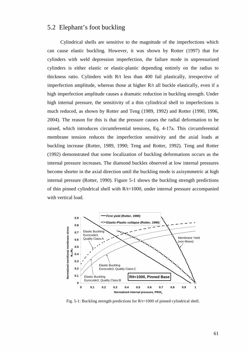
61
5.2 Elephant’s foot buckling
Cylindrical shells are sensitive to the magnitude of the imperfections which
can cause elastic buckling. However, it was shown by Rotter (1997) that for
cylinders with weld depression imperfection, the failure mode in unpressurized
cylinders is either elastic or elastic-plastic depending entirely on the radius to
thickness ratio. Cylinders with R/t less than 400 fail plastically, irrespective of
imperfection amplitude, whereas those at higher R/t all buckle elastically, even if a
high imperfection amplitude causes a dramatic reduction in buckling strength. Under
high internal pressure, the sensitivity of a thin cylindrical shell to imperfections is
much reduced, as shown by Rotter and Teng (1989, 1992) and Rotter (1990, 1996,
2004). The reason for this is that the pressure causes the radial deformation to be
raised, which introduces circumferential tensions, Eq. 4-17a. This circumferential
membrane tension reduces the imperfection sensitivity and the axial loads at
buckling increase (Rotter, 1989, 1990; Teng and Rotter, 1992). Teng and Rotter
(1992) demonstrated that some localization of buckling deformations occurs as the
internal pressure increases. The diamond buckles observed at low internal pressures
become shorter in the axial direction until the buckling mode is axisymmetric at high
internal pressure (Rotter, 1990). Figure 5-1 shows the buckling strength predictions
of thin pinned cylindrical shell with R/t=1000, under internal pressure accompanied
with vertical load.
R/t=1000, Pinned Base
0
0.1
0.2
0.3
0.4
0.5
0.6
0.7
0.8
0.9
0 0.1 0.2 0.3 0.4 0.5 0.6 0.7 0.8 0.9 1
Normalized internal pressure, PR/tfy
No
rmal
ized
mer
idio
nal
mem
bra
ne
stre
ss σσ σσ
mz/
σσ σσ cl
First yield (Rotter, 1990)
Elastic-Plastic collapse (Rotter, 1990)
Elastic BucklingEurocode3, Quality Class:C
Elastic BucklingEurocode3, Quality Class:B
Elastic BucklingEurocode3, Quality Class:A Membrane Yield
(von Mises)
Fig. 5-1: Buckling strength predictions for R/t=1000 of pinned cylindrical shell.

62
Figure 5-1 was plotted using the appropriate equations presented by Rotter
(1989, 1990). The von Mises stress, σvM, on the outside surface of the shell can then
be written as follows:
2)())((2)( bzmbzmbzmzbzmzvM νσσνσσσσσσσ θθ ++++−+= (5-1)
While the meridional membrane stress, σmz, is constant, it can be seen that the
circumferential membrane stress, σmθ, and the meridional bending stress, σbz,
dominate von Mises stress.
The membrane value of the von Mises stress, σvM0, can be found from Eq. 5-1
when the bending moment is zero and the lateral displacement, w, is wm, where wm is
the membrane theory normal deflection (Eq. 4-15).
In addition, the axial stress at first yield at a developing elephant’s foot buckle
can be predicted by Rotter ‘s (1989) approximation to the exact solution of the non-
linear elastic bending equations:
+
+
+−
−=
1
250
12.1
111 5.1
2
ρ
ρ
ρσσ
y
y
clmz
f
tf
pR (5-2)
ymzvM ft
pR
t
pR =−
−
++
+= 65.21
55.01725.23.0
2max σ
σσσ (5-3)
in which:
cl
mz
σσσ = (5-4)
t
R
400
1=ρ (5-5)
and σcl is the classical elastic buckling stress given by Eq.(2-1).
The elastic bifurcation buckling in other parts of the imperfect shell was
described by Rotter (1997) and Eurocode3 Part1.6 (2007). This elastic buckling is
related to the radius to thickness ratio and fabrication quality (Eurocode3 Part1.6,
2007) class as:
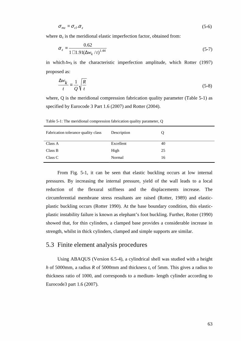
63
zclmz ασσ .= (5-6)
where αz is the meridional elastic imperfection factor, obtained from:
44.1)/(91.11
62.0
twkz ∆+
=α (5-7)
in which kw∆ is the characteristic imperfection amplitude, which Rotter (1997)
proposed as:
t
R
Qtkw 1=
∆ (5-8)
where, Q is the meridional compression fabrication quality parameter (Table 5-1) as
specified by Eurocode 3 Part 1.6 (2007) and Rotter (2004).
Table 5-1: The meridional compression fabrication quality parameter, Q
Fabrication tolerance quality class Description Q
Class A Excellent 40
Class B High 25
Class C Normal 16
From Fig. 5-1, it can be seen that elastic buckling occurs at low internal
pressures. By increasing the internal pressure, yield of the wall leads to a local
reduction of the flexural stiffness and the displacements increase. The
circumferential membrane stress resultants are raised (Rotter, 1989) and elastic-
plastic buckling occurs (Rotter 1990). At the base boundary condition, this elastic-
plastic instability failure is known as elephant’s foot buckling. Further, Rotter (1990)
showed that, for thin cylinders, a clamped base provides a considerable increase in
strength, whilst in thick cylinders, clamped and simple supports are similar.
5.3 Finite element analysis procedures
Using ABAQUS (Version 6.5-4), a cylindrical shell was studied with a height
h of 5000mm, a radius R of 5000mm and thickness ts of 5mm. This gives a radius to
thickness ratio of 1000, and corresponds to a medium- length cylinder according to
Eurocode3 part 1.6 (2007).

64
Young’s modulus, Es, and Poisson’s ratio, νs, of the metal cylindrical shell
were taken as 200 GPa and 0.3 respectively. Figure 5-2 shows the assumed stress-
strain relationship for the metal.
Strain
Stress (MPa)
250
0.125%
Fig. 5-2: Stress-Strain relation of the metal cylindrical shell.
The boundary condition at the bottom was taken as simply supported (radial,
axial and circumferential displacements restrained, but not the rotation) and for the
top, the boundary was free in all directions except for rotation about the
circumference. These boundary conditions ensure that the local buckling occurs only
at the base (Teng and Hu, 2007).
A uniform internal pressure of p and a vertical load per unit circumference of
Nz were applied to the shell. The cylindrical shell was modelled using element
SAX1. Element SAX1 is a 2-node axisymmetric general-purpose shell element with
the effect of transverse shear deformation included (ABAQUS (Version 6.5-4)).
Each node has three degrees of freedom (radial, axial displacements and a rotation).
Using an axisymmetric element for modelling the shell in this case was considered
from the fact that only axisymmetric collapse is expected. This element is also useful
for saving computational time (Teng and Hu, 2007).
Geometrically and Materially Non linear Analysis (GMNA) was used with a
modified Riks approach (Riks, 1979) to trace the nonlinear response. The Riks
method, known as the “arc-length” technique, is an incremental approach to the
solution of buckling and snap through problems (Fig. 5-3). In the Riks technique,
both the load and displacement magnitude are unknown. It is assumed that there is a
fixed coupled constraint which can be described as an arc length, ∆L, as an
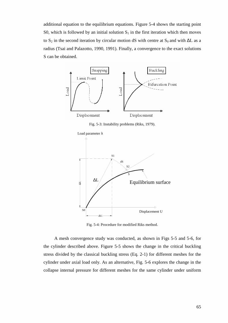
65
additional equation to the equilibrium equations. Figure 5-4 shows the starting point
S0, which is followed by an initial solution S1 in the first iteration which then moves
to S2 in the second iteration by circular motion dS with centre at S0 and with ∆L as a
radius (Tsai and Palazotto, 1990, 1991). Finally, a convergence to the exact solutions
S can be obtained.
Fig. 5-3: Instability problems (Riks, 1979).
Equilibrium surface
S1
S2
S
dS
∆L
∆U
∆λ
Displacement U
Load parameter λ
S0
Fig. 5-4: Procedure for modified Riks method.
A mesh convergence study was conducted, as shown in Figs 5-5 and 5-6, for
the cylinder described above. Figure 5-5 shows the change in the critical buckling
stress divided by the classical buckling stress (Eq. 2-1) for different meshes for the
cylinder under axial load only. As an alternative, Fig. 5-6 explores the change in the
collapse internal pressure for different meshes for the same cylinder under uniform
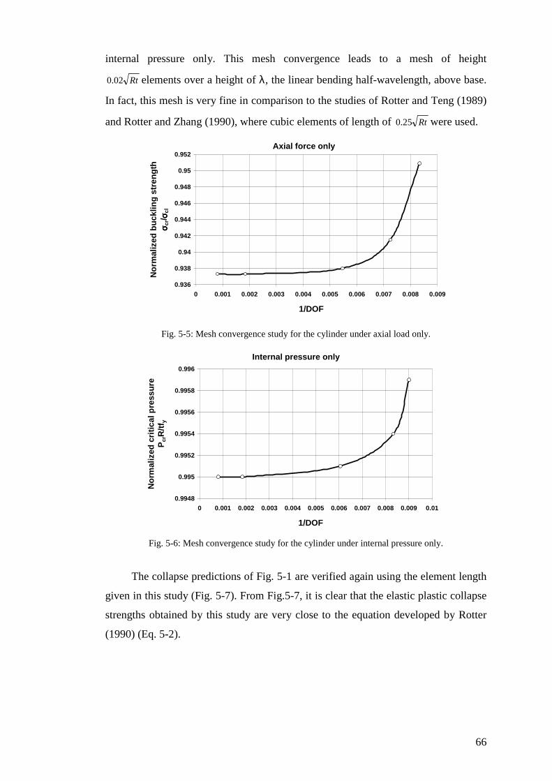
66
internal pressure only. This mesh convergence leads to a mesh of height
Rt02.0 elements over a height of λ, the linear bending half-wavelength, above base.
In fact, this mesh is very fine in comparison to the studies of Rotter and Teng (1989)
and Rotter and Zhang (1990), where cubic elements of length of Rt25.0 were used.
Axial force only
0.936
0.938
0.94
0.942
0.944
0.946
0.948
0.95
0.952
0 0.001 0.002 0.003 0.004 0.005 0.006 0.007 0.008 0.009
1/DOF
No
rmal
ized
bu
cklin
g s
tren
gth
σσ σσ c
r/ σσ σσcl
Fig. 5-5: Mesh convergence study for the cylinder under axial load only.
Internal pressure only
0.9948
0.995
0.9952
0.9954
0.9956
0.9958
0.996
0 0.001 0.002 0.003 0.004 0.005 0.006 0.007 0.008 0.009 0.01
1/DOF
No
rmal
ized
cri
tica
l pre
ssu
re
Pcr
R/t
f y
Fig. 5-6: Mesh convergence study for the cylinder under internal pressure only.
The collapse predictions of Fig. 5-1 are verified again using the element length
given in this study (Fig. 5-7). From Fig.5-7, it is clear that the elastic plastic collapse
strengths obtained by this study are very close to the equation developed by Rotter
(1990) (Eq. 5-2).
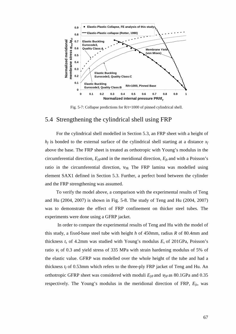
67
R/t=1000, Pinned Base0
0.1
0.2
0.3
0.4
0.5
0.6
0.7
0.8
0.9
0 0.1 0.2 0.3 0.4 0.5 0.6 0.7 0.8 0.9 1
Normalized internal pressure PR/tfy
No
rmal
ized
mer
idio
nal
m
emb
ran
e st
ress
σσ σσm
x/σσ σσ c
l
Elastic-Plastic Collapse, FE analysis of this study
Elastic-Plastic collapse (Rotter, 1990)
Elastic BucklingEurocode3, Quality Class:C
Elastic BucklingEurocode3, Quality Class:B
Elastic BucklingEurocode3, Quality Class:A Membrane Yield
(von Mises)
Fig. 5-7: Collapse predictions for R/t=1000 of pinned cylindrical shell.
5.4 Strengthening the cylindrical shell using FRP
For the cylindrical shell modelled in Section 5.3, an FRP sheet with a height of
hf is bonded to the external surface of the cylindrical shell starting at a distance xf
above the base. The FRP sheet is treated as orthotropic with Young’s modulus in the
circumferential direction, Efθ and in the meridional direction, Efz and with a Poisson’s
ratio in the circumferential direction, νfθ. The FRP lamina was modelled using
element SAX1 defined in Section 5.3. Further, a perfect bond between the cylinder
and the FRP strengthening was assumed.
To verify the model above, a comparison with the experimental results of Teng
and Hu (2004, 2007) is shown in Fig. 5-8. The study of Teng and Hu (2004, 2007)
was to demonstrate the effect of FRP confinement on thicker steel tubes. The
experiments were done using a GFRP jacket.
In order to compare the experimental results of Teng and Hu with the model of
this study, a fixed-base steel tube with height h of 450mm, radius R of 80.4mm and
thickness ts of 4.2mm was studied with Young’s modulus Es of 201GPa, Poisson’s
ratio νs of 0.3 and yield stress of 335 MPa with strain hardening modulus of 5% of
the elastic value. GFRP was modelled over the whole height of the tube and had a
thickness tf of 0.53mm which refers to the three-ply FRP jacket of Teng and Hu. An
orthotropic GFRP sheet was considered with moduli Efθ and νfθ as 80.1GPa and 0.35
respectively. The Young’s modulus in the meridional direction of FRP, Efz, was

68
ignored first, as in the work of Teng and Hu, because of its small stiffness. It was
later taken as 3GPa.
It is worth mentioning that Teng and Hu modelled their tests using ABAQUS
using B33 elements oriented in the hoop direction. B33 is a bi-cubic beam element
with six degrees of freedom per node. The height of its cross section was taken as the
height of the shell element. Also, elements S4R were used to model the tube. S4R is
4-node doubly curved general-purpose shell, with reduced integration with hourglass
control and the effect of transverse shear deformation included (ABAQUS (Version
6.5-4)). Each node has six degrees of freedom (three displacements and three
rotations).
0
100
200
300
400
500
600
700
800
900
0 2 4 6 8 10 12 14
Axial shortening (mm)
Axi
al lo
ad (
KN
)
Teng and Hu experiment, with FRP(2007)Teng and Hu experiment, without FRP (2007) Teng and Hu FE model, with FRP (2007)Teng and Hu FE model, Without FRP (2007)This study with GFRP no axial stiffness
FE analysis of this study, without FRP
FE analysis of this study, with FRP, no FRP axial stiffness
FE analysis of this study, with FRP, with FRP axial stiffness
Fig. 5-8: Load-axial shortening curves.
Figure 5-8 shows the experimental load-deflection curves for a matched pair of
experiments with and without FRP strengthening. The calculated load-deflection
curves of Teng and Hu are also shown together with the calculated curves from this
study.
These tests and calculations show that the strength and ductility of the steel
tube are increased greatly by using FRP. Further, the shell elements to model the
FRP used here give a failure load much closer to the experiment than the FE analysis
of Teng and Hu (2007) where beam elements were used. Furthermore, a higher
collapse load is observed when the axial stiffness of the FRP sheet is included.
However, the above tube is a thick cylindrical shell, where R/t was around 19.
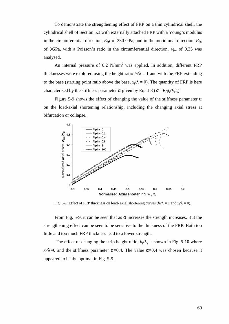
69
To demonstrate the strengthening effect of FRP on a thin cylindrical shell, the
cylindrical shell of Section 5.3 with externally attached FRP with a Young’s modulus
in the circumferential direction, Efθ, of 230 GPa, and in the meridional direction, Efz,
of 3GPa, with a Poisson’s ratio in the circumferential direction, νfθ, of 0.35 was
analysed.
An internal pressure of 0.2 N/mm2 was applied. In addition, different FRP
thicknesses were explored using the height ratio hf/λ = 1 and with the FRP extending
to the base (starting point ratio above the base, xf/λ = 0). The quantity of FRP is here
characterised by the stiffness parameter α given by Eq. 4-8 (α =Efθtf/Ests).
Figure 5-9 shows the effect of changing the value of the stiffness parameter α
on the load-axial shortening relationship, including the changing axial stress at
bifurcation or collapse.
0
0.1
0.2
0.3
0.4
0.5
0.6
0.3 0.35 0.4 0.45 0.5 0.55 0.6 0.65 0.7
Normalized Axial shortening w z /ts
Nor
mal
ized
axi
al s
tres
s σσ σσ m
z/σσ σσ c
l
Alpha=0Alpha=0.2Alpha=0.4Alpha=0.8Alpha=2Alpha=100
Fig. 5-9: Effect of FRP thickness on load- axial shortening curves (hf/λ = 1 and xf/λ = 0).
From Fig. 5-9, it can be seen that as α increases the strength increases. But the
strengthening effect can be seen to be sensitive to the thickness of the FRP. Both too
little and too much FRP thickness lead to a lower strength.
The effect of changing the strip height ratio, hf/λ, is shown in Fig. 5-10 where
xf/λ=0 and the stiffness parameter α=0.4. The value α=0.4 was chosen because it
appeared to be the optimal in Fig. 5-9.

70
0
0.1
0.2
0.3
0.4
0.5
0.6
0.7
0.3 0.35 0.4 0.45 0.5 0.55 0.6 0.65 0.7
Normalized Axial shortening w z /ts
Nor
mal
ized
axi
al s
tres
s σσ σσ m
z/σσ σσ c
l
height ratio=0
height ratio=0.5
height ratio=0.75
height ratio=1
height ratio=1.25
Fig. 5-10: Effect of height ratio on load –axial shortening curves (α = 0.4 and xf/λ = 0).
Figure 5-10 also shows that the height ratio affects the strength. It is clear that
if a larger or smaller height ratio than the optimal one is used, the strength is reduced.
The effect of changing the starting point ratio of FRP, xf/λ, was explored. The result
is in Fig. 5-11 where the thickness ratio α and end point ratio (xf+hf)/λ are fixed at
0.4 and 0.75 respectively, these being the optimal values from Fig. 5-10.
0.55
0.56
0.57
0.58
0.59
0.6
0.61
0.62
0.63
0.64
0.65
0.65 0.66 0.67 0.68 0.69 0.7
Normalized Axial shortening w z /ts
Nor
mal
ized
axi
al s
tres
s σσ σσ m
z/σσ σσ c
l
xf/Lamda=0xf/Lamda=0.05xf/Lamda=0.1xf/Lamda=0.15xf/Lamda=0.2
Fig. 5-11: Effect of starting point ratio on load-axial shortening curves (α = 0.4 and (xf+hf)/λ=0.75).
Figure 5-11 shows that the strength decreases when xf is increased, but it is not
as sensitive to this parameter as it is to tf and hf, as indicated by Figs 5-9 and 5-10
respectively.
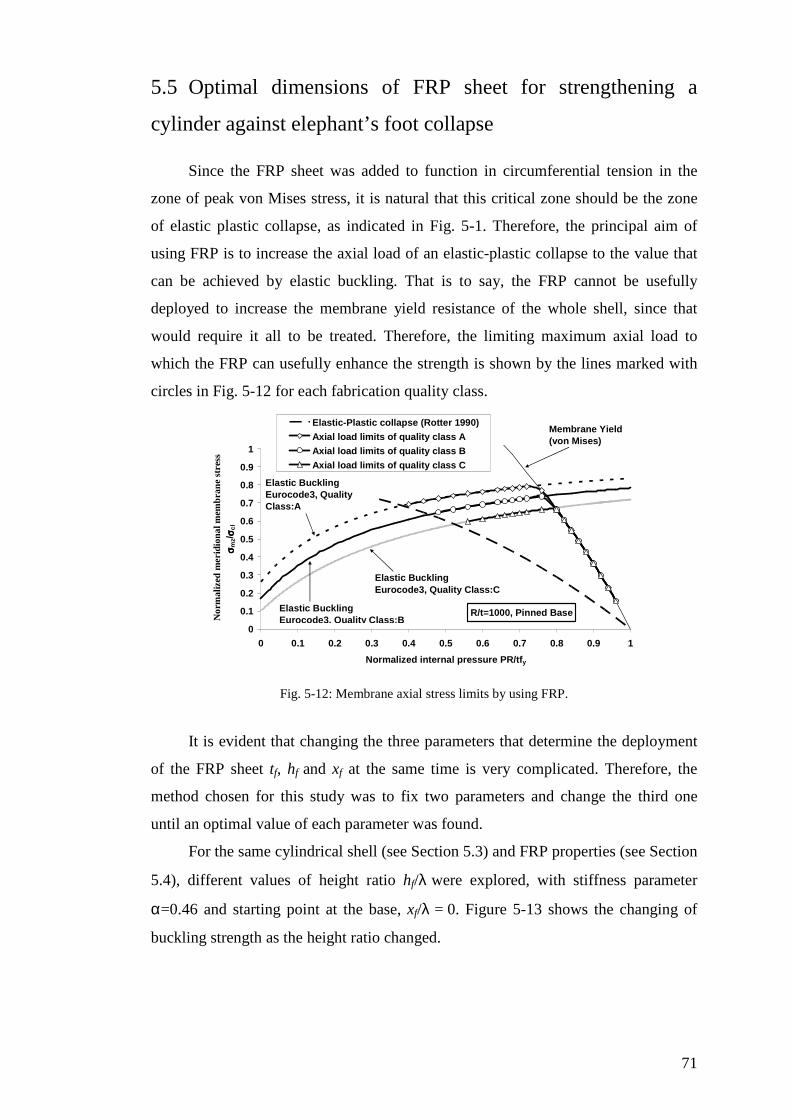
71
5.5 Optimal dimensions of FRP sheet for strengthening a
cylinder against elephant’s foot collapse
Since the FRP sheet was added to function in circumferential tension in the
zone of peak von Mises stress, it is natural that this critical zone should be the zone
of elastic plastic collapse, as indicated in Fig. 5-1. Therefore, the principal aim of
using FRP is to increase the axial load of an elastic-plastic collapse to the value that
can be achieved by elastic buckling. That is to say, the FRP cannot be usefully
deployed to increase the membrane yield resistance of the whole shell, since that
would require it all to be treated. Therefore, the limiting maximum axial load to
which the FRP can usefully enhance the strength is shown by the lines marked with
circles in Fig. 5-12 for each fabrication quality class.
R/t=1000, Pinned Base
0
0.1
0.2
0.3
0.4
0.5
0.6
0.7
0.8
0.9
1
0 0.1 0.2 0.3 0.4 0.5 0.6 0.7 0.8 0.9 1
Normalized internal pressure PR/tfy
Nor
mal
ized
mer
idio
nal m
embr
ane
stre
ss
σσ σσ mz/
σσ σσ cl
Elastic-Plastic collapse (Rotter 1990)
Axial load limits of quality class A
Axial load limits of quality class B
Axial load limits of quality class C
Elastic BucklingEurocode3, Quality Class:C
Elastic BucklingEurocode3, Quality Class:B
Elastic BucklingEurocode3, Quality Class:A
Membrane Yield (von Mises)
Fig. 5-12: Membrane axial stress limits by using FRP.
It is evident that changing the three parameters that determine the deployment
of the FRP sheet tf, hf and xf at the same time is very complicated. Therefore, the
method chosen for this study was to fix two parameters and change the third one
until an optimal value of each parameter was found.
For the same cylindrical shell (see Section 5.3) and FRP properties (see Section
5.4), different values of height ratio hf/λ were explored, with stiffness parameter
α=0.46 and starting point at the base, xf/λ = 0. Figure 5-13 shows the changing of
buckling strength as the height ratio changed.

72
0
0.1
0.2
0.3
0.4
0.5
0.6
0.7
0.8
0.9
1
0 0.1 0.2 0.3 0.4 0.5 0.6 0.7 0.8 0.9 1
Normalized internal pressure PR/tsfy
No
rmal
ized
axi
al m
emb
ran
e st
ress
σ σ σ σm
x/σσ σσ
cl height ratio=1
height ratio=0.75
height ratio=0.5
Elastic buckling -Class C
Elastic buckling -Class B
Elastic buckling -Class A
Elastic plastic collapseNo FRP
Membrane von mises=fy
Fig. 5-13: Effect of height ratio on buckling strength (α = 0.46 and xf/λ = 0).
The three values of height ratio used in Fig. 5-13 indicate that a height ratio of
0.75 is close to the value needed to obtain the maximum buckling strength.
Next, different values of the stiffness parameter α (Eq. 4-8) were explored,
with the fixed height ratio of 0.75 and xf/λ=0. The changing buckling strength is
shown in Fig. 5-14 of the three values shown (α=0.23, 0.46 and 0.69). The highest
buckling strength is found when α=0.46. This suggest that a value around α=0.5 may
be optimal.
0
0.1
0.2
0.3
0.4
0.5
0.6
0.7
0.8
0.9
1
0 0.1 0.2 0.3 0.4 0.5 0.6 0.7 0.8 0.9 1
Normalized internal pressure PR/tsfy
No
rmal
ized
axi
al m
emb
ran
e st
ress
σσ σσm
x/σσ σσ c
l
Alpha=0.23
Alpha=0.46
Alpha=0.69
Elastic buckling -Class C
Elastic buckling -Class B
Elastic buckling -Class A
Elastic plastic collapseNo FRP
Membrane von mises=fy
Fig. 5-14: Effect of FRP thickness on buckling strength (hf/λ = 0.75 and xf/λ = 0).
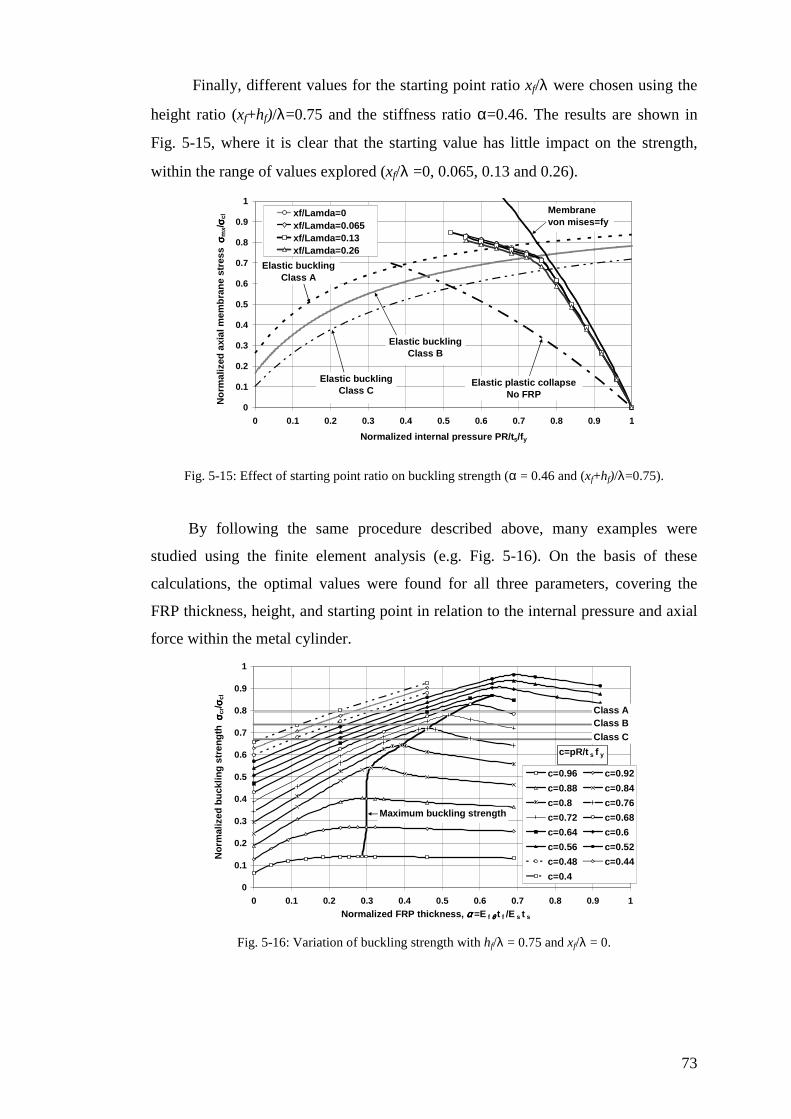
73
Finally, different values for the starting point ratio xf/λ were chosen using the
height ratio (xf+hf)/λ=0.75 and the stiffness ratio α=0.46. The results are shown in
Fig. 5-15, where it is clear that the starting value has little impact on the strength,
within the range of values explored (xf/λ =0, 0.065, 0.13 and 0.26).
0
0.1
0.2
0.3
0.4
0.5
0.6
0.7
0.8
0.9
1
0 0.1 0.2 0.3 0.4 0.5 0.6 0.7 0.8 0.9 1
Normalized internal pressure PR/ts/fy
No
rmal
ized
axi
al m
emb
ran
e st
ress
σ σ σ σm
x/σσ σσ c
l xf/Lamda=0xf/Lamda=0.065xf/Lamda=0.13xf/Lamda=0.26
Elastic buckling Class C
Elastic buckling Class B
Elastic buckling Class A
Elastic plastic collapseNo FRP
Membrane von mises=fy
Fig. 5-15: Effect of starting point ratio on buckling strength (α = 0.46 and (xf+hf)/λ=0.75).
By following the same procedure described above, many examples were
studied using the finite element analysis (e.g. Fig. 5-16). On the basis of these
calculations, the optimal values were found for all three parameters, covering the
FRP thickness, height, and starting point in relation to the internal pressure and axial
force within the metal cylinder.
0
0.1
0.2
0.3
0.4
0.5
0.6
0.7
0.8
0.9
1
0 0.1 0.2 0.3 0.4 0.5 0.6 0.7 0.8 0.9 1
Normalized FRP thickness, αααα =E f θθθθ t f /E s t s
No
rmal
ized
bu
cklin
g s
tren
gth
σ σ σ σcr
/ σσ σσcl
c=0.96 c=0.92
c=0.88 c=0.84
c=0.8 c=0.76
c=0.72 c=0.68
c=0.64 c=0.6
c=0.56 c=0.52
c=0.48 c=0.44
c=0.4
Class AClass BClass C
Maximum buckling strength
c=pR/t s f y
Fig. 5-16: Variation of buckling strength with hf/λ = 0.75 and xf/λ = 0.

74
The results of the optimisation process are shown in Figs 5-17, 5-18 and 5-19.
For every design pressure and identified quality class, an optimum value of the three
parameters of the normalized FRP thickness α (Eq. 4-8), height ωb=πhf/λb (Eq. 4-
24e), and starting point ωc=πxf/λ (Eq. 4-28e) was found.
The internal pressure p was characteristic here in terms of the parameter:
0vMsn t
pRP
σ= (5-9)
in which:
σvM0 is the membrane von Mises stress (Section 5.2) and λb is the meridional bending
half- wavelength for the section where the FRP was attached (Eq. 4-16a).
R/t=1000
0
0.1
0.2
0.3
0.4
0.5
0.6
0.6 0.65 0.7 0.75 0.8 0.85 0.9 0.95 1
Normalized internal pressure P n =pR/t s σσσσ vM0
No
rmal
ized
FR
P t
hic
knes
s αα αα=
Ef θθ θθ
t f/E
sts
Membrane Von Mises=fy
Quality Class A
Quality Class B
Quality Class C
Fig. 5-17: Optimal FRP thickness, tf.
R/t=1000
1.5
1.75
2
2.25
2.5
2.75
3
3.25
0.6 0.65 0.7 0.75 0.8 0.85 0.9 0.95 1
Normalized internal pressure P n =pR/t s σσσσ vM0
No
rmal
ized
FR
P h
eig
ht
ωω ωω b= ππ ππ
hf/ λλ λλ
b
Membrane von Mises=fy
Quality Class A
Quality Class B
Quality Class C
Fig. 5-18: Optimal FRP height, hf.

75
R/t=1000
0
0.1
0.2
0.3
0.4
0.5
0.6
0.6 0.65 0.7 0.75 0.8 0.85 0.9 0.95 1
Normalized internal pressure P n =pR/t s σσσσ vM0
No
rmal
ized
FR
P s
tart
ing
po
int
ωω ωω c= ππ ππ
x f/ λλ λλ
Membrane von Mises=fyQuality Class AQuality Class BQuality Class C
Fig. 5-19: Optimal FRP starting point, xf .
This results show that the optimal height (Fig. 5-18) is relatively insensitive to
the quality class and internal pressure, but that the optimum stiffness ratio α and
starting point of ωc both vary very strongly with internal pressure.
5.6 Empirical formulas for the optimal attached FRP
From the above optimisation, it can be seen clearly that there are two parts for
each of the required parameters. The high pressure part is required to achieve the
membrane yield strength, while the low pressure is required to ensure that the elastic
imperfect buckling strength is reached (Fig. 5-12).
5.6.1 The required parameters for membrane yield
A roughly exponential relationship can be observed from Figs 5-17, 5-18 and
5-19 to obtain the parameters tf, hf and xf for the membrane yield part, it is suggested
that the following expression can give a good empirical match:
ncPn ecPBA )cos(+ (5-10)
in which the constants A, B and C take different values for each parameter. The
dimensionless pressure parameter Pn is given in Eq. 5-9.
5.6.1.1 The required FRP thickness, tf
The constant values of A, B and C for the FRP thickness can be as follows:

76
7.390.66 0.00068cos(7.39 )
Pf f nn
s s
E tP e
E t
θα = = − (5-11)
5.6.1.2 The required FRP height, hf
A, B and C for the FRP height are shown in Eq. 5-12:
10.51.79 0.0000687cos(10.5 )
Pf nb n
b
hP e
πω
λ= = − (5-12)
5.6.1.3 The required FRP starting point, xf
Deriving the constants A, B and C from Fig. 5-19 for the FRP starting point
gives:
nPn
fc eP
x 33.7)33.7cos(00056.0591.0 −==
λπ
ω (5-13)
5.6.2 The required parameters for elastic buckling part
For the elastic buckling part, the function for the FRP parameters can be
formed as Eq. 5-14:
nCPBeA+ (5-14)
5.6.2.1 The required FRP thickness, tf
Producing the constant values of A, B and C from Fig. 5-17 for each class,
which obtain a good estimation gives:
2.481.31 0.288
Pf f n
s s
E te
E t
θα = = − + for Class A (5-15a)
3.811.09 0.083
Pf f n
s s
E te
E t
θα = = − + for Class B (5-15b)
3.641.72 0.118
Pf f n
s s
E te
E t
θα = = − + for Class C (5-15c)
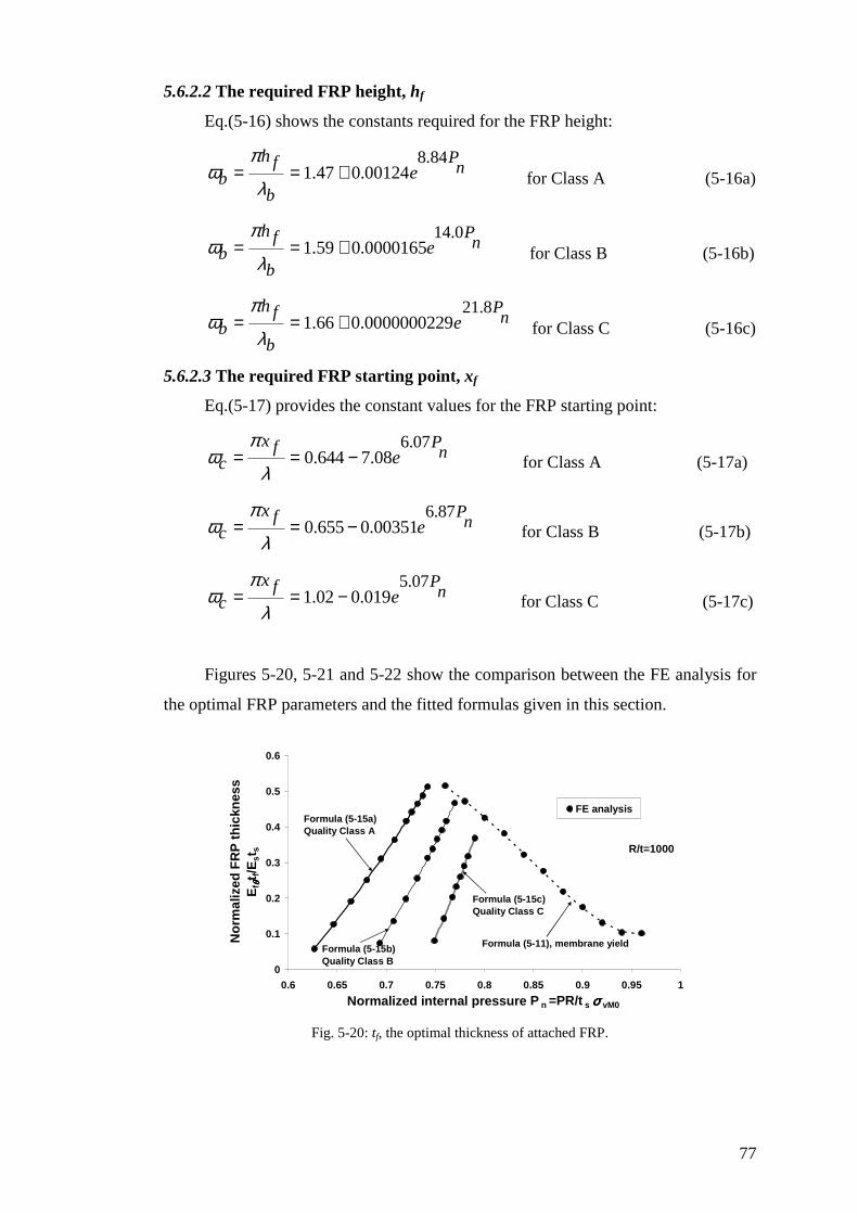
77
5.6.2.2 The required FRP height, hf
Eq.(5-16) shows the constants required for the FRP height:
8.841.47 0.00124
Pf nb
b
he
πω
λ= = + for Class A (5-16a)
14.01.59 0.0000165
Pf nb
b
he
πω
λ= = + for Class B (5-16b)
21.81.66 0.0000000229
Pf nb
b
he
πω
λ= = + for Class C (5-16c)
5.6.2.3 The required FRP starting point, xf
Eq.(5-17) provides the constant values for the FRP starting point:
6.070.644 7.08
Pf nc
xe
πω
λ= = − for Class A (5-17a)
6.870.655 0.00351
Pf nc
xe
πω
λ= = − for Class B (5-17b)
5.071.02 0.019
Pf nc
xe
πω
λ= = − for Class C (5-17c)
Figures 5-20, 5-21 and 5-22 show the comparison between the FE analysis for
the optimal FRP parameters and the fitted formulas given in this section.
R/t=1000
0
0.1
0.2
0.3
0.4
0.5
0.6
0.6 0.65 0.7 0.75 0.8 0.85 0.9 0.95 1
Normalized internal pressure P n =PR/t s σσσσ vM0
No
rmal
ized
FR
P t
hic
knes
s E
f θθ θθt f/
Est
s
FE analysis
Formula (5-11), membrane yield
Formula (5-15a) Quality Class A
Formula (5-15b) Quality Class B
Formula (5-15c) Quality Class C
Fig. 5-20: tf, the optimal thickness of attached FRP.
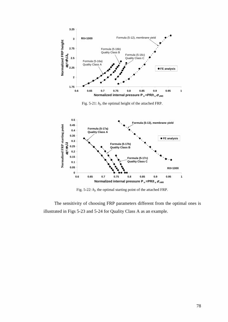
78
R/t=1000
1.75
2
2.25
2.5
2.75
3
3.25
0.6 0.65 0.7 0.75 0.8 0.85 0.9 0.95 1
Normalized internal pressure P n =PR/t s σσσσ vM0
No
rmal
ized
FR
P h
eig
ht
ωω ωω b= ππ ππ
hf/ λλ λλ
bFE analysis
Formula (5-12), membrane yield
Formula (5-16a) Quality Class A
Formula (5-16b) Quality Class B
Formula (5-16c) Quality Class C
Fig. 5-21: hf, the optimal height of the attached FRP.
R/t=1000
0
0.05
0.1
0.15
0.2
0.25
0.3
0.35
0.4
0.45
0.5
0.6 0.65 0.7 0.75 0.8 0.85 0.9 0.95 1
Normalized internal pressure P n =PR/t s σσσσ vM0
Nor
mal
ized
FR
P s
tart
ing
poin
t ωω ωω c
= ππ ππx f
/ λλ λλ
FE analysis
Formula (5-13), membrane yield
Formula (5-17a) Quality Class A
Formula (5-17b) Quality Class B
Formula (5-17c) Quality Class C
Fig. 5-22: hf, the optimal starting point of the attached FRP.
The sensitivity of choosing FRP parameters different from the optimal ones is
illustrated in Figs 5-23 and 5-24 for Quality Class A as an example.
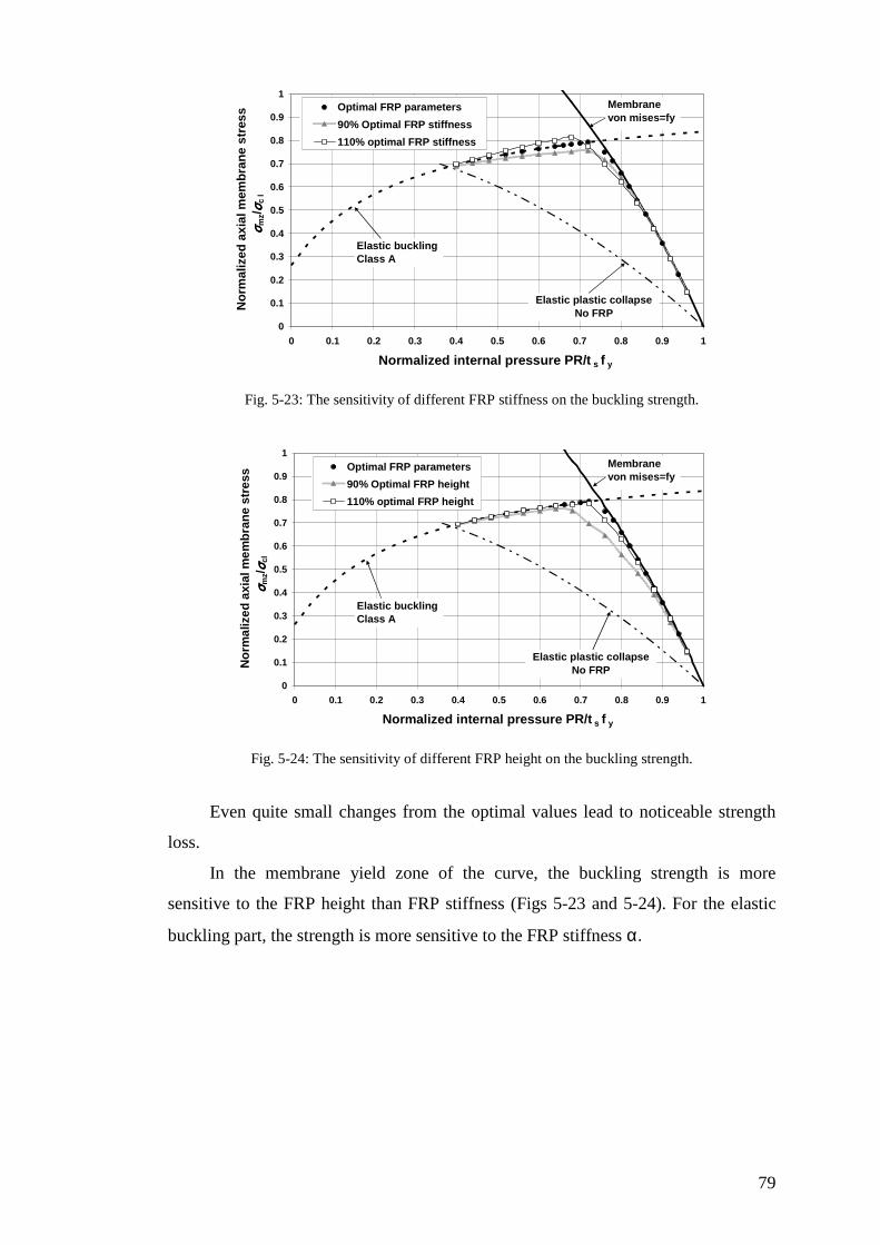
79
0
0.1
0.2
0.3
0.4
0.5
0.6
0.7
0.8
0.9
1
0 0.1 0.2 0.3 0.4 0.5 0.6 0.7 0.8 0.9 1
Normalized internal pressure PR/t s f y
No
rmal
ized
axi
al m
emb
ran
e st
ress
σσ σσ m
z/σσ σσ c
l
Optimal FRP parameters
90% Optimal FRP stiffness
110% optimal FRP stiffness
Elastic buckling -Class A
Elastic plastic collapseNo FRP
Membrane von mises=fy
Fig. 5-23: The sensitivity of different FRP stiffness on the buckling strength.
0
0.1
0.2
0.3
0.4
0.5
0.6
0.7
0.8
0.9
1
0 0.1 0.2 0.3 0.4 0.5 0.6 0.7 0.8 0.9 1
Normalized internal pressure PR/t s f y
No
rmal
ized
axi
al m
emb
ran
e st
ress
σσ σσ m
z/σσ σσ c
l
Optimal FRP parameters
90% Optimal FRP height
110% optimal FRP height
Elastic buckling -Class A
Elastic plastic collapseNo FRP
Membrane von mises=fy
Fig. 5-24: The sensitivity of different FRP height on the buckling strength.
Even quite small changes from the optimal values lead to noticeable strength
loss.
In the membrane yield zone of the curve, the buckling strength is more
sensitive to the FRP height than FRP stiffness (Figs 5-23 and 5-24). For the elastic
buckling part, the strength is more sensitive to the FRP stiffness α.

80
5.7 Summary
This chapter has studied the use of FRP to strengthen a cylindrical shell under
internal pressure accompanied by vertical load. Geometrically and Materially Non
linear Analysis (GMNA) has been used to explore the gain in buckling strength for
an FRP-strengthened steel cylindrical shell. Moreover, the optimal FRP sheet
required to prevent elephant’s foot buckling for a cylindrical shell of radius to
thickness ratio of 1000 as an example has been obtained. The fabrication quality
classes were used, and empirical formulas were produced to identify the optimal
strengthening condition.
81
Chapter 6
Elastic buckling of FRP-strengthened cylinders with
axisymmetric imperfections
6.1 Introduction
The susceptibility of axially compressed cylinders to geometric imperfections
when buckling in the elastic range has been recognized for over 50 years. One of the
most damaging imperfection forms is a local axisymmetric imperfection. This
chapter explores the possibility of enhancing the cylinder buckling strength by local
application of an FRP repair.
Local axisymmetric imperfections are commonly present at welding joints.
Geometrically Nonlinear Analysis with Imperfection (GNIA) is undertaken in this
chapter to investigate the elastic bifurcation buckling under axial loads of an FRP-
strengthened cylindrical shell with axisymmetric inward imperfections.
The chapter begins with a description of previous research on the buckling of
unpressurized axisymmetric-imperfect cylinders.
Next, a finite element analysis using Geometrically Nonlinear Analysis with
Imperfections (GNIA) is used to obtain the bifurcation buckling strength predictions.
Then, the effect of FRP strengthening on the buckling strength of a cylindrical
shell with an axisymmetric imperfection is explored.
Finally, a summary of the work done in this chapter is presented.
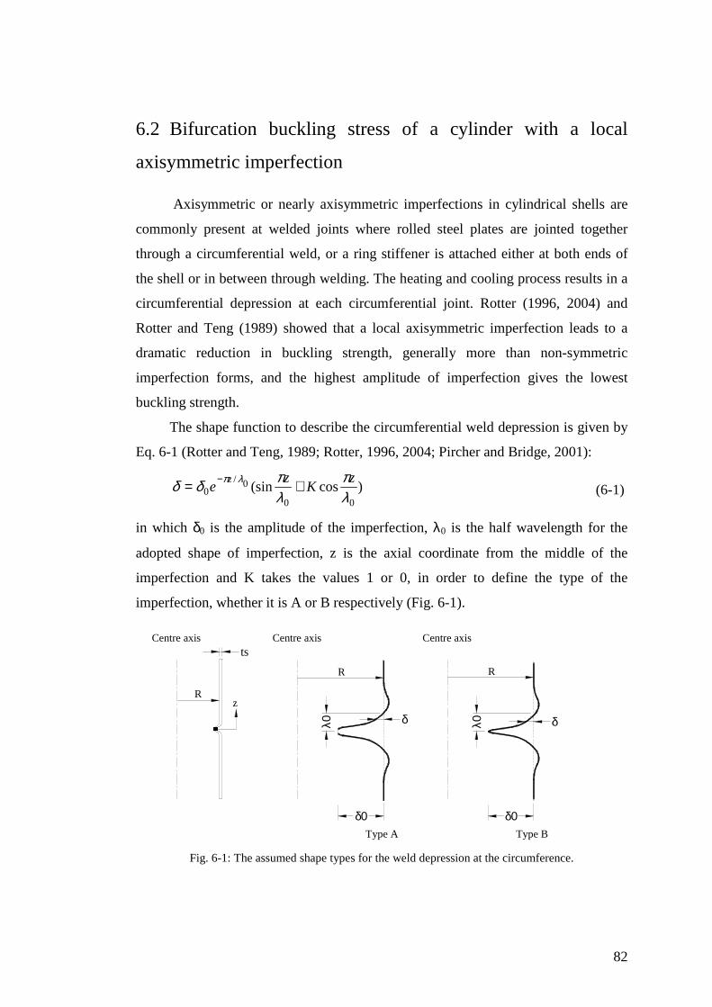
82
6.2 Bifurcation buckling stress of a cylinder with a local
axisymmetric imperfection
Axisymmetric or nearly axisymmetric imperfections in cylindrical shells are
commonly present at welded joints where rolled steel plates are jointed together
through a circumferential weld, or a ring stiffener is attached either at both ends of
the shell or in between through welding. The heating and cooling process results in a
circumferential depression at each circumferential joint. Rotter (1996, 2004) and
Rotter and Teng (1989) showed that a local axisymmetric imperfection leads to a
dramatic reduction in buckling strength, generally more than non-symmetric
imperfection forms, and the highest amplitude of imperfection gives the lowest
buckling strength.
The shape function to describe the circumferential weld depression is given by
Eq. 6-1 (Rotter and Teng, 1989; Rotter, 1996, 2004; Pircher and Bridge, 2001):
)cos(sin00
0/0 λ
πλπδδ λπ z
Kz
ez += −
(6-1)
in which δ0 is the amplitude of the imperfection, λ0 is the half wavelength for the
adopted shape of imperfection, z is the axial coordinate from the middle of the
imperfection and K takes the values 1 or 0, in order to define the type of the
imperfection, whether it is A or B respectively (Fig. 6-1).
Centre axisCentre axis Centre axis
R
R R
z
δ0 δ0
δ δλ0 λ0
Type A Type B
ts
Fig. 6-1: The assumed shape types for the weld depression at the circumference.

83
Type A (K=1) was assumed to resist flexural yielding completely during
cooling, whereas Type B (K=0) was assumed to be completely flexible during
cooling (Rotter and Teng 1989). This local imperfection decays very rapidly away
from the weld joint, as shown in Fig. 6-1. However, it was shown that Type A
provides considerably less buckling strength than Type B, so the former is more
commonly used (Rotter and Zhang 1990; Teng and Rotter, 1992; Rotter, 1997;
Pircher and Bridge, 2001). Moreover, Pircher and Bridge (2001) studied the effect of
changing of both K and λ0 in Eq. 6-1 on the buckling strength of the imperfect
cylinder. Their study found that K=1 and λ0=λ, the bending half wavelength (Eq. 2-
3), produce the lowest buckling strength for both the short cylinder and the long
cylinder. This result confirms the work done by Rotter (1997), where the half
wavelength for the imperfection equal to the bending half wavelength was found to
produce a situation close to the worst case scenario when elastic buckling occurs.
The interaction between the adjacent imperfect joints (Fig. 6-2) has been
explored by Rotter (1996) and Pircher and Bridge (2001).
Fig. 6-2: Buckling modes and boundary conditions (Pircher and Bridge, 2001).
Rotter (1996) showed that the boundary conditions of A-A leads to much lower
buckling loads than the repeated S-S weld. Further, Pircher and Bridge (2001)
observed that the influence of the boundary conditions becomes insignificant with a
large half-strake height. For instance, no difference in buckling strength between S-S
and A-A was obtained with a half-strake height of 6λ for an imperfection amplitude
δ0 equal to ts, the thickness of the strake.
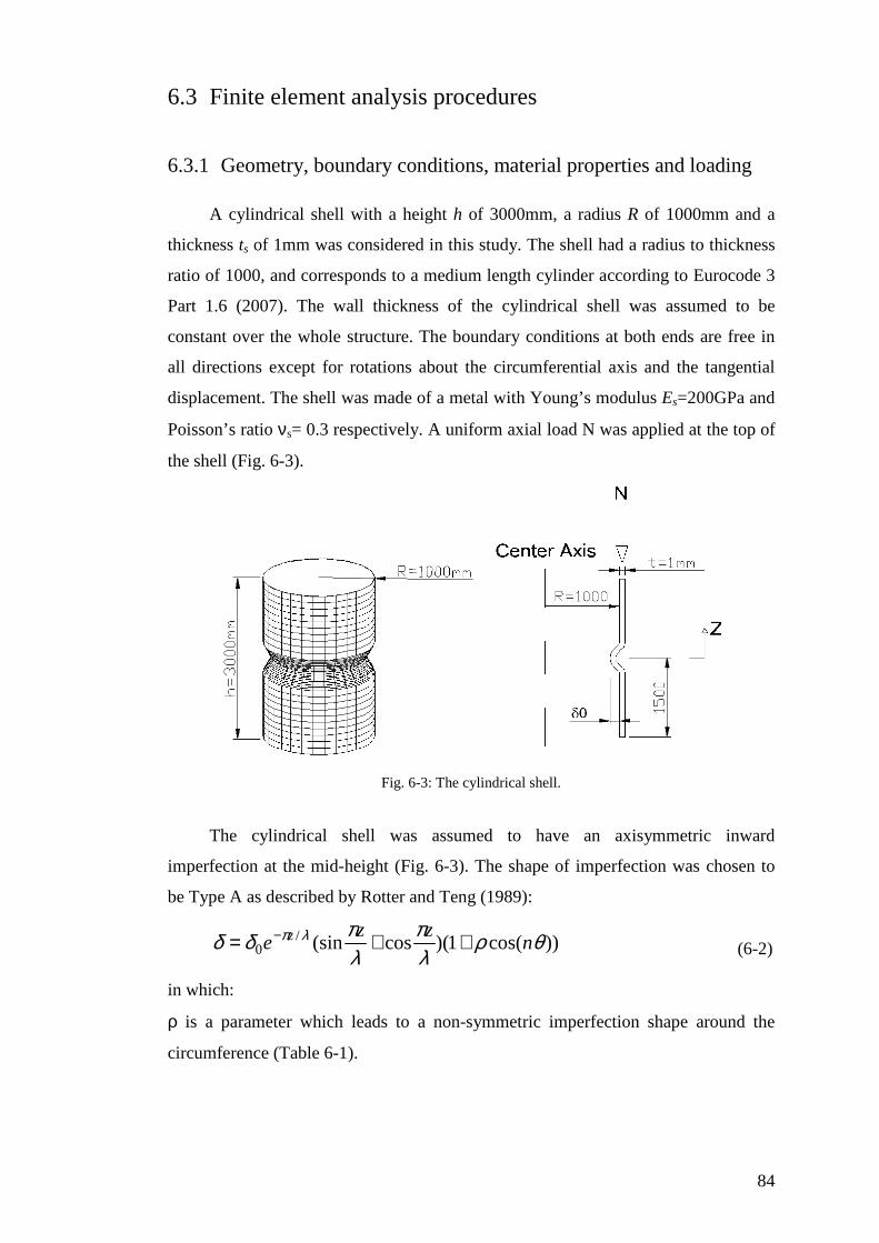
84
6.3 Finite element analysis procedures
6.3.1 Geometry, boundary conditions, material properties and loading
A cylindrical shell with a height h of 3000mm, a radius R of 1000mm and a
thickness ts of 1mm was considered in this study. The shell had a radius to thickness
ratio of 1000, and corresponds to a medium length cylinder according to Eurocode 3
Part 1.6 (2007). The wall thickness of the cylindrical shell was assumed to be
constant over the whole structure. The boundary conditions at both ends are free in
all directions except for rotations about the circumferential axis and the tangential
displacement. The shell was made of a metal with Young’s modulus Es=200GPa and
Poisson’s ratio νs= 0.3 respectively. A uniform axial load N was applied at the top of
the shell (Fig. 6-3).
Fig. 6-3: The cylindrical shell.
The cylindrical shell was assumed to have an axisymmetric inward
imperfection at the mid-height (Fig. 6-3). The shape of imperfection was chosen to
be Type A as described by Rotter and Teng (1989):
))cos(1)(cos(sin/0 θρ
λπ
λπδδ λπ n
zze z ++= −
(6-2)
in which:
ρ is a parameter which leads to a non-symmetric imperfection shape around the
circumference (Table 6-1).

85
n is the circumferential mode number at the bifurcation load (Table 6-1).
θ is the circumferential coordinate.
Table 6-1: The parameter r and the mode number for each imperfection amplitude.
Normalized initial dent depth, δ0/ts ρ n
0.1 0.002 26
0.25 0.002 24
0.5 0.002 22
1 0.005 18
1.5 0.02 14
2 0.06 12
0.2
0.21
0.22
0.23
0.24
0.25
0.26
0.27
0.2 0.21 0.22 0.23 0.24 0.25 0.26 0.27 0.28
Normalized axial shortening wz/ts
No
rmal
ized
axi
al s
tres
s σσ σσ m
x/σσ σσ c
l
r=0
r=0.025
r=0.05
r=0.06
r=0.07
r=0.1
ρ=0
ρ=0.025
ρ=0.05
ρ=0.06
ρ=0.07
ρ=0.01
a) Axial stress- axial shortening curves.
0.233
0.234
0.235
0.236
0.237
0.238
0.239
0.24
0.241
0.242
0.243
0 0.01 0.02 0.03 0.04 0.05 0.06 0.07 0.08 0.09 0.1
parameter, ρρρρ
No
rmal
ized
bu
cklin
g s
tren
gth
σσ σσcr
/ σσ σσcl
b) The parameter ρ against the normalized buckling strength.
Fig. 6-4: The effect of the parameter ρ on the buckling behaviour (δ0/ts=2).
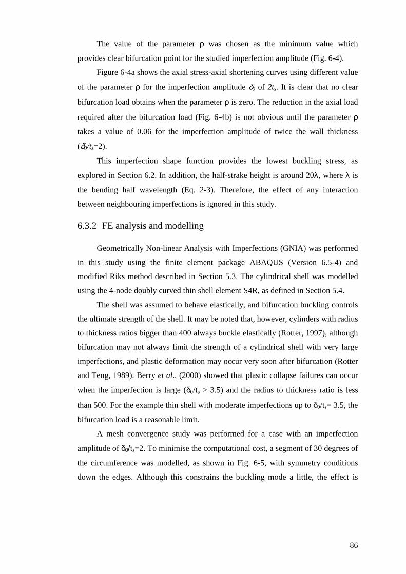
86
The value of the parameter ρ was chosen as the minimum value which
provides clear bifurcation point for the studied imperfection amplitude (Fig. 6-4).
Figure 6-4a shows the axial stress-axial shortening curves using different value
of the parameter ρ for the imperfection amplitude δ0 of 2ts. It is clear that no clear
bifurcation load obtains when the parameter ρ is zero. The reduction in the axial load
required after the bifurcation load (Fig. 6-4b) is not obvious until the parameter ρ
takes a value of 0.06 for the imperfection amplitude of twice the wall thickness
(δ0/ts=2).
This imperfection shape function provides the lowest buckling stress, as
explored in Section 6.2. In addition, the half-strake height is around 20λ, where λ is
the bending half wavelength (Eq. 2-3). Therefore, the effect of any interaction
between neighbouring imperfections is ignored in this study.
6.3.2 FE analysis and modelling
Geometrically Non-linear Analysis with Imperfections (GNIA) was performed
in this study using the finite element package ABAQUS (Version 6.5-4) and
modified Riks method described in Section 5.3. The cylindrical shell was modelled
using the 4-node doubly curved thin shell element S4R, as defined in Section 5.4.
The shell was assumed to behave elastically, and bifurcation buckling controls
the ultimate strength of the shell. It may be noted that, however, cylinders with radius
to thickness ratios bigger than 400 always buckle elastically (Rotter, 1997), although
bifurcation may not always limit the strength of a cylindrical shell with very large
imperfections, and plastic deformation may occur very soon after bifurcation (Rotter
and Teng, 1989). Berry et al., (2000) showed that plastic collapse failures can occur
when the imperfection is large (δ0/ts > 3.5) and the radius to thickness ratio is less
than 500. For the example thin shell with moderate imperfections up to δ0/ts= 3.5, the
bifurcation load is a reasonable limit.
A mesh convergence study was performed for a case with an imperfection
amplitude of δ0/ts=2. To minimise the computational cost, a segment of 30 degrees of
the circumference was modelled, as shown in Fig. 6-5, with symmetry conditions
down the edges. Although this constrains the buckling mode a little, the effect is

87
small because this thin shell buckles with very many waves around the
circumference (Rotter, 2004).
Fig. 6-5: The modelled part.
The mesh convergence was adopted in two directions: circumferentially and
meridionally. In order to find the finest circumferential mesh, a constant number of
50 rows was assumed and the number of the circumferential columns was increased
gradually. The change in the bifurcation stress on increasing the number of
circumferential columns is shown in Fig. 6-6. It can be seen that a mesh of 80
columns in the circumferential direction is accurate enough for this study. Then, the
number of rows was increased (Fig. 6-7) for a mesh with 80 columns around the 30o
circumference. The BIAS command of ABAQUS for rows was used. This command
allows the nodes to be more concentrated near the imperfect edge and more widely
spaced near the top of the cylinder.
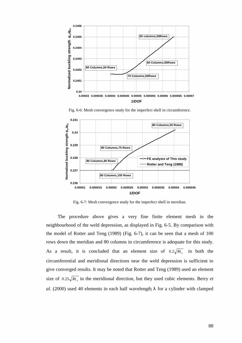
88
0.24
0.2401
0.2402
0.2403
0.2404
0.2405
0.2406
0.00003 0.000035 0.00004 0.000045 0.00005 0.000055 0.00006 0.000065 0.00007
1/DOF
No
rmal
ized
bu
cklin
g s
tren
gth
σσ σσcr
/ σσ σσcl
50 columns,50Rows
70 Columns,50Rows
80 Columns,50 Rows
60 Columns,50Rows
Fig. 6-6: Mesh convergence study for the imperfect shell in circumference.
0.236
0.237
0.238
0.239
0.24
0.241
0.00001 0.000015 0.00002 0.000025 0.00003 0.000035 0.00004 0.000045
1/DOF
No
rmal
ized
bu
cklin
g s
tren
gth
σσ σσcr
/ σσ σσcl
FE analysis of This study
Rotter and Teng (1989)
80 Columns,50 Rows
80 Columns,75 Rows
80 Columns,90 Rows
80 Columns,100 Rows
Fig. 6-7: Mesh convergence study for the imperfect shell in meridian.
The procedure above gives a very fine finite element mesh in the
neighbourhood of the weld depression, as displayed in Fig. 6-5. By comparison with
the model of Rotter and Teng (1989) (Fig. 6-7), it can be seen that a mesh of 100
rows down the meridian and 80 columns in circumference is adequate for this study.
As a result, it is concluded that an element size of sRt2.0 in both the
circumferential and meridional directions near the weld depression is sufficient to
give converged results. It may be noted that Rotter and Teng (1989) used an element
size of sRt25.0 in the meridional direction, but they used cubic elements. Berry et
al. (2000) used 40 elements in each half wavelength λ for a cylinder with clamped
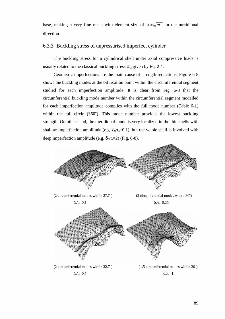
89
base, making a very fine mesh with element size of sRt06.0 in the meridional
direction.
6.3.3 Buckling stress of unpressurised imperfect cylinder
The buckling stress for a cylindrical shell under axial compressive loads is
usually related to the classical buckling stress σcl given by Eq. 2-1.
Geometric imperfections are the main cause of strength reductions. Figure 6-8
shows the buckling modes at the bifurcation point within the circumferential segment
studied for each imperfection amplitude. It is clear from Fig. 6-8 that the
circumferential buckling mode number within the circumferential segment modelled
for each imperfection amplitude complies with the full mode number (Table 6-1)
within the full circle (360o). This mode number provides the lowest buckling
strength. On other hand, the meridional mode is very localized in the thin shells with
shallow imperfection amplitude (e.g. δ0/ts=0.1), but the whole shell is involved with
deep imperfection amplitude (e.g. δ0/ts=2) (Fig. 6-8).
(2 circumferential modes within 27.7o) (2 circumferential modes within 30o)
δ0/ts=0.1 δ0/ts=0.25
(2 circumferential modes within 32.7o) (1.5 circumferential modes within 30o)
δ0/ts=0.5 δ0/ts=1
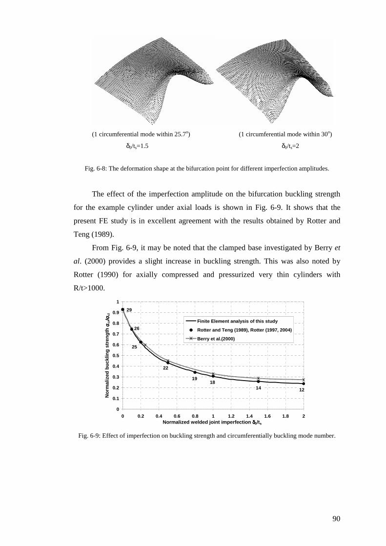
90
(1 circumferential mode within 25.7o) (1 circumferential mode within 30o)
δ0/ts=1.5 δ0/ts=2
Fig. 6-8: The deformation shape at the bifurcation point for different imperfection amplitudes.
The effect of the imperfection amplitude on the bifurcation buckling strength
for the example cylinder under axial loads is shown in Fig. 6-9. It shows that the
present FE study is in excellent agreement with the results obtained by Rotter and
Teng (1989).
From Fig. 6-9, it may be noted that the clamped base investigated by Berry et
al. (2000) provides a slight increase in buckling strength. This was also noted by
Rotter (1990) for axially compressed and pressurized very thin cylinders with
R/t>1000.
0
0.1
0.2
0.3
0.4
0.5
0.6
0.7
0.8
0.9
1
0 0.2 0.4 0.6 0.8 1 1.2 1.4 1.6 1.8 2Normalized welded joint imperfection δδδδ0/ts
No
rmal
ized
bu
cklin
g s
tren
gth
σσ σσcr
/σ/σ /σ/σcl
Finite Element analysis of this study
Rotter and Teng (1989), Rotter (1997, 2004)
Berry et al.(2000)
29
26
25
22
1918
14 12
Fig. 6-9: Effect of imperfection on buckling strength and circumferentially buckling mode number.
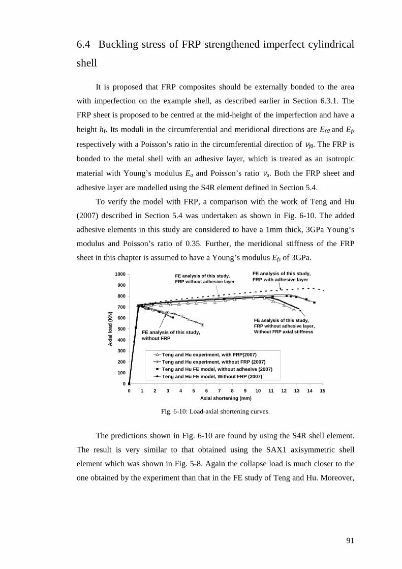
91
6.4 Buckling stress of FRP strengthened imperfect cylindrical
shell
It is proposed that FRP composites should be externally bonded to the area
with imperfection on the example shell, as described earlier in Section 6.3.1. The
FRP sheet is proposed to be centred at the mid-height of the imperfection and have a
height hf. Its moduli in the circumferential and meridional directions are Efθ and Efz
respectively with a Poisson’s ratio in the circumferential direction of νfθ. The FRP is
bonded to the metal shell with an adhesive layer, which is treated as an isotropic
material with Young’s modulus Ea and Poisson’s ratio νa. Both the FRP sheet and
adhesive layer are modelled using the S4R element defined in Section 5.4.
To verify the model with FRP, a comparison with the work of Teng and Hu
(2007) described in Section 5.4 was undertaken as shown in Fig. 6-10. The added
adhesive elements in this study are considered to have a 1mm thick, 3GPa Young’s
modulus and Poisson’s ratio of 0.35. Further, the meridional stiffness of the FRP
sheet in this chapter is assumed to have a Young’s modulus Efz of 3GPa.
0
100
200
300
400
500
600
700
800
900
1000
0 1 2 3 4 5 6 7 8 9 10 11 12 13 14 15
Axial shortening (mm)
Axi
al lo
ad (
KN
)
Teng and Hu experiment, with FRP(2007)
Teng and Hu experiment, without FRP (2007)
Teng and Hu FE model, without adhesive (2007)
Teng and Hu FE model, Without FRP (2007)
FE analysis of this study, FRP with adhesive layer
FE analysis of this study, without FRP
FE analysis of this study, FRP without adhesive layer
FE analysis of this study, FRP without adhesive layer, Without FRP axial stiffness
Fig. 6-10: Load-axial shortening curves.
The predictions shown in Fig. 6-10 are found by using the S4R shell element.
The result is very similar to that obtained using the SAX1 axisymmetric shell
element which was shown in Fig. 5-8. Again the collapse load is much closer to the
one obtained by the experiment than that in the FE study of Teng and Hu. Moreover,

92
a small increase in the buckling load is evident when the FRP is separated from the
shell. The predicted change that a significant adhesive layer would make to the
experiment of Teng and Hu (2007) can be seen in Fig. 6-10. The extra adhesive
thickness clearly has a slightly beneficial effect.
To demonstrate the strengthening effect of FRP on a thin cylindrical shell, the
cylindrical shell of Section 6.3.1 with externally attached FRP was analysed. It had a
Young’s modulus in the circumferential direction, Efθ, of 230 GPa, and in the
meridional direction, Efz, of 3GPa, with a Poisson’s ratio in the circumferential
direction, νfθ, of 0.35. The results, shown in Figs 6-11 and 6-12, are compared with
FRP with Young’s modulus in the circumferential direction of 100GPa in terms of
FRP dimensionless extensional stiffness (Efθtf/Ests) and FRP dimensionless bending
stiffness (Efθtf3/Ests
3). An imperfection with amplitude δ0/ts= 2 was assumed and the
FRP height ratio of hf/λ=2 was used in these calculations.
0
0.1
0.2
0.3
0.4
0.5
0.6
0.7
0.8
0.9
1
0 1 2 3 4 5 6
Normalized FRP extensional stiffness E f θθθθ t f /E s t s
No
rmal
ized
bu
cklin
g s
tren
gth
σσ σσcr
/ σσ σσcl
Efr=100GPa
Efr=230GPa
Efθθθθ=100GPa
Efθθθθ=230GPa
Fig. 6-11: Effect of the FRP extensional stiffness on the buckling strength of an imperfect shell (hf/λ
=2 and δ0/ts = 2).
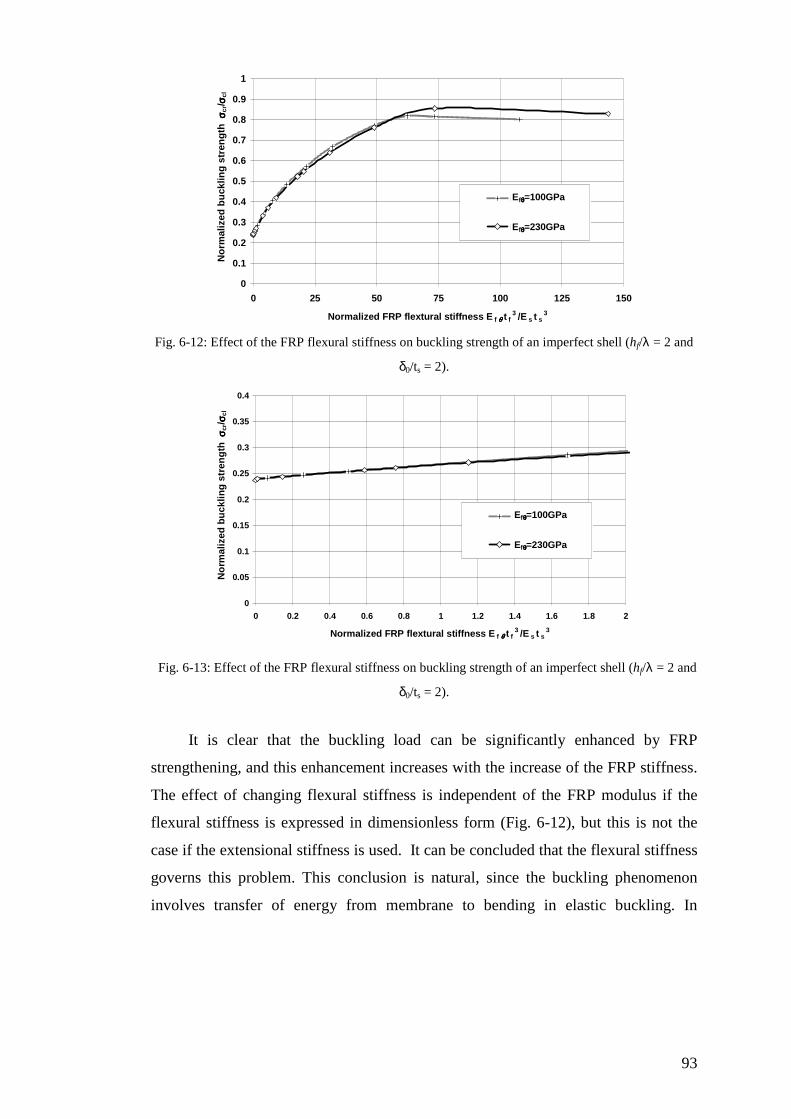
93
0
0.1
0.2
0.3
0.4
0.5
0.6
0.7
0.8
0.9
1
0 25 50 75 100 125 150
Normalized FRP flextural stiffness E f θθθθ t f3 /E s t s
3
No
rmal
ized
bu
cklin
g s
tren
gth
σσ σσcr
/ σσ σσcl
Efr=100GPa
Efr=230GPa
Efθθθθ=100GPa
Efθθθθ=230GPa
Fig. 6-12: Effect of the FRP flexural stiffness on buckling strength of an imperfect shell (hf/λ = 2 and
δ0/ts = 2).
0
0.05
0.1
0.15
0.2
0.25
0.3
0.35
0.4
0 0.2 0.4 0.6 0.8 1 1.2 1.4 1.6 1.8 2
Normalized FRP flextural stiffness E f θθθθ t f3 /E s t s
3
No
rmal
ized
bu
cklin
g s
tren
gth
σσ σσcr
/ σσ σσcl
Efr=100GPa
Efr=230GPa
Efθθθθ=100GPa
Efθθθθ=230GPa
Fig. 6-13: Effect of the FRP flexural stiffness on buckling strength of an imperfect shell (hf/λ = 2 and
δ0/ts = 2).
It is clear that the buckling load can be significantly enhanced by FRP
strengthening, and this enhancement increases with the increase of the FRP stiffness.
The effect of changing flexural stiffness is independent of the FRP modulus if the
flexural stiffness is expressed in dimensionless form (Fig. 6-12), but this is not the
case if the extensional stiffness is used. It can be concluded that the flexural stiffness
governs this problem. This conclusion is natural, since the buckling phenomenon
involves transfer of energy from membrane to bending in elastic buckling. In

94
contrast, the circumferential membrane stress resultants play a big role in the plastic
collapse (Chapter 5).
The effect of the adhesive stiffness on the bifurcation buckling strength is
explored in Fig. 6-14 for two adhesive Young’s moduli: 1GPa and 3GPa. It is clear
from Fig. 6-14 that there is a considerable increase in strength when the thickness of
adhesive is increased, but this is only the case for unrealistic thicknesses (Fig. 6-14).
If the gains due to changes in the normalized adhesive stiffness (Fig. 6-14) are
compared with those due to changes in the FRP normalized stiffness (Fig. 6-12), it is
clear that an increase in adhesive thickness is much effective in increasing the
buckling strength than an increase in the quantity or stiffness of FRP. This result is to
be expected, as the adhesive thickness separates the FRP from the shell and this
greatly enhances the flexural stiffness of the composite shell. This phenomenon is
very important in the use of FRP to enhance the buckling strength of a structure.
Most studies of the use of FRP to achieve strengthening were concerned with
material failure (Chapter 2), and for these conditions, effective confinement of the
concrete, for example, required a thin adhesive layer between the FRP and the parent
structure. Here, by contrast, a thick layer of FRP is extremely beneficial, and may be
necessary for the strengthening measures to be effective.
0
0.1
0.2
0.3
0.4
0.5
0.6
0.7
0.8
0.9
0 2 4 6 8 10 12 14 16 18 20Normalized adhesive flexural stiffness E a t a
3 /E s t s3
No
rmal
ized
bu
cklin
g s
tren
gth
σσ σσcr
/ σσ σσcl
Ea=3GPa
Ea=1GPa
Fig. 6-14: Effect of adhesive flexural stiffness enhancement on buckling strength (hf/λ = 2,
Efθtf3/Ests
3=0.76 and δ0/ts = 2).
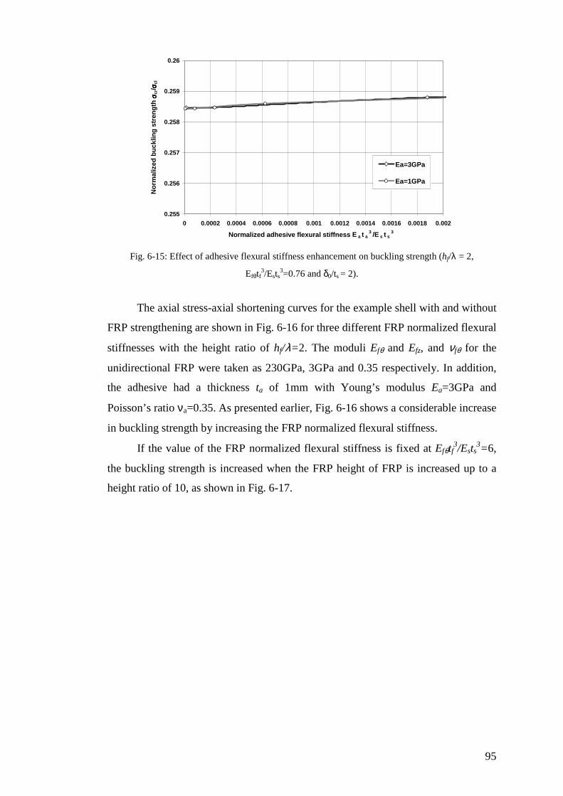
95
0.255
0.256
0.257
0.258
0.259
0.26
0 0.0002 0.0004 0.0006 0.0008 0.001 0.0012 0.0014 0.0016 0.0018 0.002
Normalized adhesive flexural stiffness E a t a3 /E s t s
3
No
rmal
ized
bu
cklin
g s
tren
gth
σσ σσcr
/ σσ σσcl
Ea=3GPa
Ea=1GPa
Fig. 6-15: Effect of adhesive flexural stiffness enhancement on buckling strength (hf/λ = 2,
Efθtf3/Ests
3=0.76 and δ0/ts = 2).
The axial stress-axial shortening curves for the example shell with and without
FRP strengthening are shown in Fig. 6-16 for three different FRP normalized flexural
stiffnesses with the height ratio of hf/λ=2. The moduli Efθ and Efz, and νfθ for the
unidirectional FRP were taken as 230GPa, 3GPa and 0.35 respectively. In addition,
the adhesive had a thickness ta of 1mm with Young’s modulus Ea=3GPa and
Poisson’s ratio νa=0.35. As presented earlier, Fig. 6-16 shows a considerable increase
in buckling strength by increasing the FRP normalized flexural stiffness.
If the value of the FRP normalized flexural stiffness is fixed at Efθtf3/Ests
3=6,
the buckling strength is increased when the FRP height of FRP is increased up to a
height ratio of 10, as shown in Fig. 6-17.
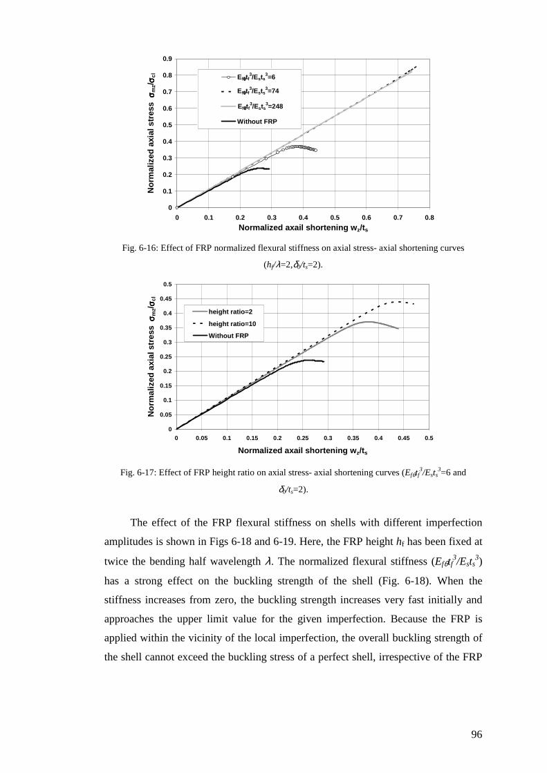
96
0
0.1
0.2
0.3
0.4
0.5
0.6
0.7
0.8
0.9
0 0.1 0.2 0.3 0.4 0.5 0.6 0.7 0.8
Normalized axail shortening wz/ts
No
rmal
ized
axi
al s
tres
s σσ σσ
mz/ σσ σσ
cl Eftf3/Et3=6
Eftf3/Et3=74
Eftf3/Et3=248
Without FRP
Efθθθθtf3/Ests
3=6
Efθθθθtf3/Ests
3=74
Efθθθθtf3/Ests
3=248
Fig. 6-16: Effect of FRP normalized flexural stiffness on axial stress- axial shortening curves
(hf/λ=2,δ0/ts=2).
0
0.05
0.1
0.15
0.2
0.25
0.3
0.35
0.4
0.45
0.5
0 0.05 0.1 0.15 0.2 0.25 0.3 0.35 0.4 0.45 0.5
Normalized axail shortening wz/ts
No
rmal
ized
axi
al s
tres
s σσ σσ
mz/
σσ σσ cl
height ratio=2
height ratio=10
Without FRP
Fig. 6-17: Effect of FRP height ratio on axial stress- axial shortening curves (Efθtf3/Ests
3=6 and
δ0/ts=2).
The effect of the FRP flexural stiffness on shells with different imperfection
amplitudes is shown in Figs 6-18 and 6-19. Here, the FRP height hf has been fixed at
twice the bending half wavelength λ. The normalized flexural stiffness (Efθtf3/Ests
3)
has a strong effect on the buckling strength of the shell (Fig. 6-18). When the
stiffness increases from zero, the buckling strength increases very fast initially and
approaches the upper limit value for the given imperfection. Because the FRP is
applied within the vicinity of the local imperfection, the overall buckling strength of
the shell cannot exceed the buckling stress of a perfect shell, irrespective of the FRP
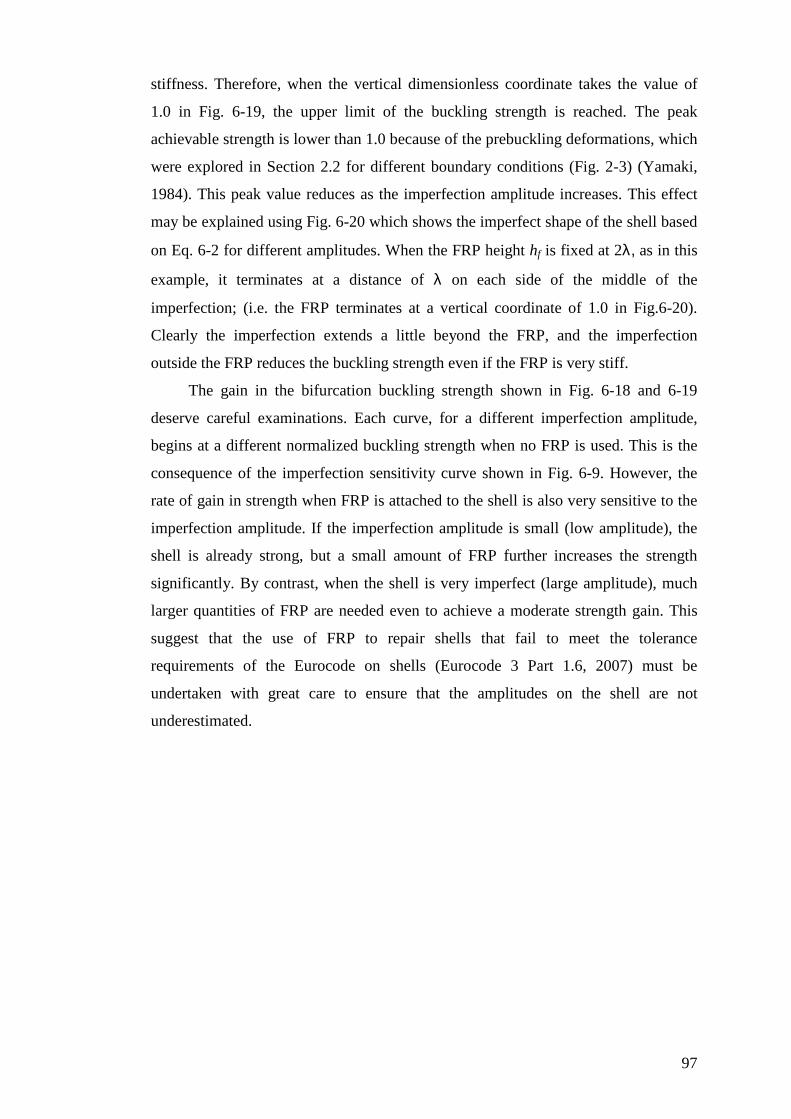
97
stiffness. Therefore, when the vertical dimensionless coordinate takes the value of
1.0 in Fig. 6-19, the upper limit of the buckling strength is reached. The peak
achievable strength is lower than 1.0 because of the prebuckling deformations, which
were explored in Section 2.2 for different boundary conditions (Fig. 2-3) (Yamaki,
1984). This peak value reduces as the imperfection amplitude increases. This effect
may be explained using Fig. 6-20 which shows the imperfect shape of the shell based
on Eq. 6-2 for different amplitudes. When the FRP height hf is fixed at 2λ, as in this
example, it terminates at a distance of λ on each side of the middle of the
imperfection; (i.e. the FRP terminates at a vertical coordinate of 1.0 in Fig.6-20).
Clearly the imperfection extends a little beyond the FRP, and the imperfection
outside the FRP reduces the buckling strength even if the FRP is very stiff.
The gain in the bifurcation buckling strength shown in Fig. 6-18 and 6-19
deserve careful examinations. Each curve, for a different imperfection amplitude,
begins at a different normalized buckling strength when no FRP is used. This is the
consequence of the imperfection sensitivity curve shown in Fig. 6-9. However, the
rate of gain in strength when FRP is attached to the shell is also very sensitive to the
imperfection amplitude. If the imperfection amplitude is small (low amplitude), the
shell is already strong, but a small amount of FRP further increases the strength
significantly. By contrast, when the shell is very imperfect (large amplitude), much
larger quantities of FRP are needed even to achieve a moderate strength gain. This
suggest that the use of FRP to repair shells that fail to meet the tolerance
requirements of the Eurocode on shells (Eurocode 3 Part 1.6, 2007) must be
undertaken with great care to ensure that the amplitudes on the shell are not
underestimated.
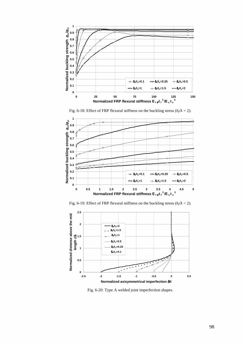
98
0
0.1
0.2
0.3
0.4
0.5
0.6
0.7
0.8
0.9
1
0 25 50 75 100 125 150
Normalized FRP flexural stiffness E f θθθθ t f3 /E s t s
3
No
rmal
ized
bu
cklin
g s
tren
gth
σσ σσcr
/ σσ σσcl
d0/t=0.1 d0/t=0.25 d0/t=0.5
d0/t=1 d0/t=1.5 d0/t=2
δδδδ0/ts=0.1 δδδδ0/ts=0.25 δδδδ0/ts=0.5
δδδδ0/ts=1 δδδδ0/ts=1.5 δδδδ0/ts=2
Fig. 6-18: Effect of FRP flexural stiffness on the buckling stress (hf/λ = 2).
0
0.1
0.2
0.3
0.4
0.5
0.6
0.7
0.8
0.9
1
0 0.5 1 1.5 2 2.5 3 3.5 4 4.5 5
Normalized FRP flexural stiffness E f θθθθ t f3 /E s t s
3
No
rmal
ized
bu
cklin
g s
tren
gth
σσ σσcr
/ σσ σσcl
d0/t=0.1 d0/t=0.25 d0/t=0.5
d0/t=1 d0/t=1.5 d0/t=2
δδδδ0/ts=0.1 δδδδ0/ts=0.25 δδδδ0/ts=0.5
δδδδ0/ts=1 δδδδ0/ts=1.5 δδδδ0/ts=2
Fig. 6-19: Effect of FRP flexural stiffness on the buckling stress (hf/λ = 2).
0
0.5
1
1.5
2
2.5
-2.5 -2 -1.5 -1 -0.5 0 0.5
Normalized axisymmetrical imperfection δδδδ/t
No
rmal
ized
dis
tan
se a
bo
ve t
he
mid
le
ng
th z
/ λλ λλ
d0/t=2
d0/t=1.5
d0/t=1
d0/t=0.5
d0/t=0.25
d0/t=0.1δδδδ0/ts=0.1
δδδδ0/ts=0.25
δδδδ0/ts=0.5
δδδδ0/ts=1
δδδδ0/ts=1.5
δδδδ0/ts=2
Fig. 6-20: Type A welded joint imperfection shapes.
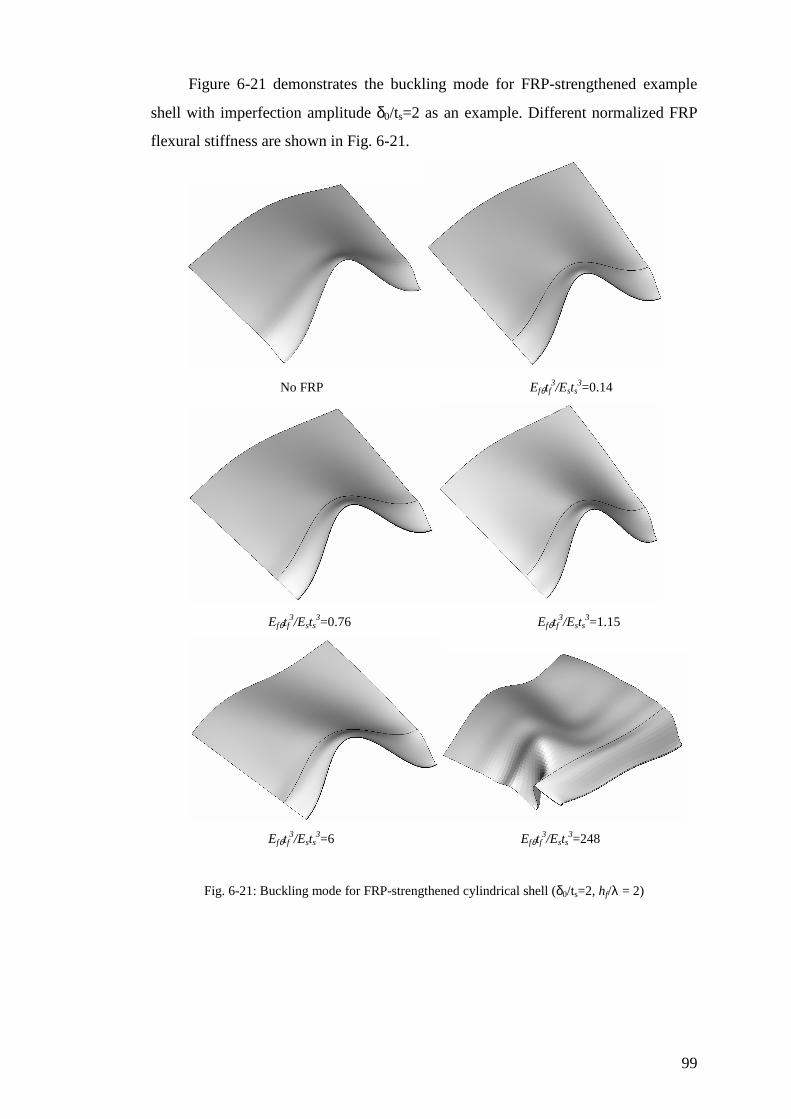
99
Figure 6-21 demonstrates the buckling mode for FRP-strengthened example
shell with imperfection amplitude δ0/ts=2 as an example. Different normalized FRP
flexural stiffness are shown in Fig. 6-21.
No FRP Efθtf3/Ests
3=0.14
Efθtf3/Ests
3=0.76 Efθtf3/Ests
3=1.15
Efθtf
3/Ests3=6 Efθtf
3/Ests3=248
Fig. 6-21: Buckling mode for FRP-strengthened cylindrical shell (δ0/ts=2, hf/λ = 2)
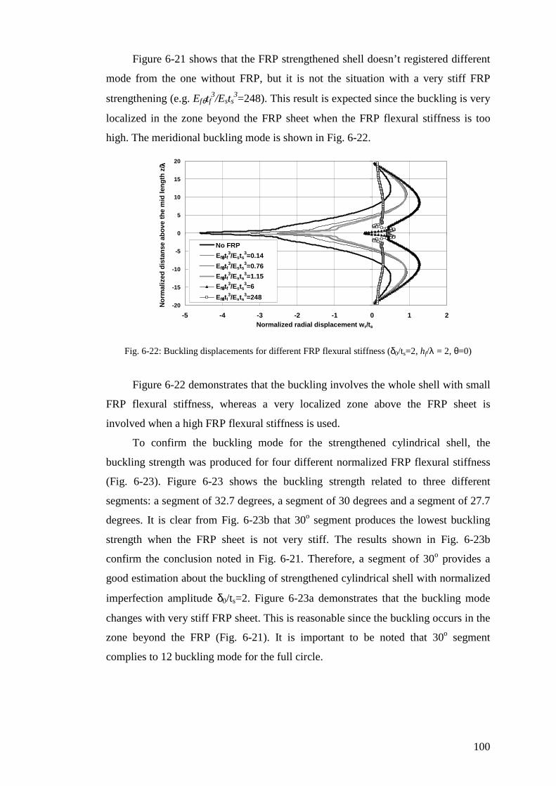
100
Figure 6-21 shows that the FRP strengthened shell doesn’t registered different
mode from the one without FRP, but it is not the situation with a very stiff FRP
strengthening (e.g. Efθtf3/Ests
3=248). This result is expected since the buckling is very
localized in the zone beyond the FRP sheet when the FRP flexural stiffness is too
high. The meridional buckling mode is shown in Fig. 6-22.
-20
-15
-10
-5
0
5
10
15
20
-5 -4 -3 -2 -1 0 1 2Normalized radial displacement wr/ts
No
rmal
ized
dis
tan
se a
bo
ve t
he
mid
len
gth
z/ λλ λλ
No FRP
Eftf3/ests3=0.14
Eftf3/Ests3=0.76
Eftf3/ests3=1.15
Eftf3/Ests3=6
Eftf3/Ests3=248
Efθθθθtf3/Ests
3=0.14
Efθθθθtf3/Ests
3=0.76
Efθθθθtf3/Ests
3=1.15
Efθθθθtf3/Ests
3=6
Efθθθθtf3/Ests
3=248
Fig. 6-22: Buckling displacements for different FRP flexural stiffness (δ0/ts=2, hf/λ = 2, θ=0)
Figure 6-22 demonstrates that the buckling involves the whole shell with small
FRP flexural stiffness, whereas a very localized zone above the FRP sheet is
involved when a high FRP flexural stiffness is used.
To confirm the buckling mode for the strengthened cylindrical shell, the
buckling strength was produced for four different normalized FRP flexural stiffness
(Fig. 6-23). Figure 6-23 shows the buckling strength related to three different
segments: a segment of 32.7 degrees, a segment of 30 degrees and a segment of 27.7
degrees. It is clear from Fig. 6-23b that 30o segment produces the lowest buckling
strength when the FRP sheet is not very stiff. The results shown in Fig. 6-23b
confirm the conclusion noted in Fig. 6-21. Therefore, a segment of 30o provides a
good estimation about the buckling of strengthened cylindrical shell with normalized
imperfection amplitude δ0/ts=2. Figure 6-23a demonstrates that the buckling mode
changes with very stiff FRP sheet. This is reasonable since the buckling occurs in the
zone beyond the FRP (Fig. 6-21). It is important to be noted that 30o segment
complies to 12 buckling mode for the full circle.
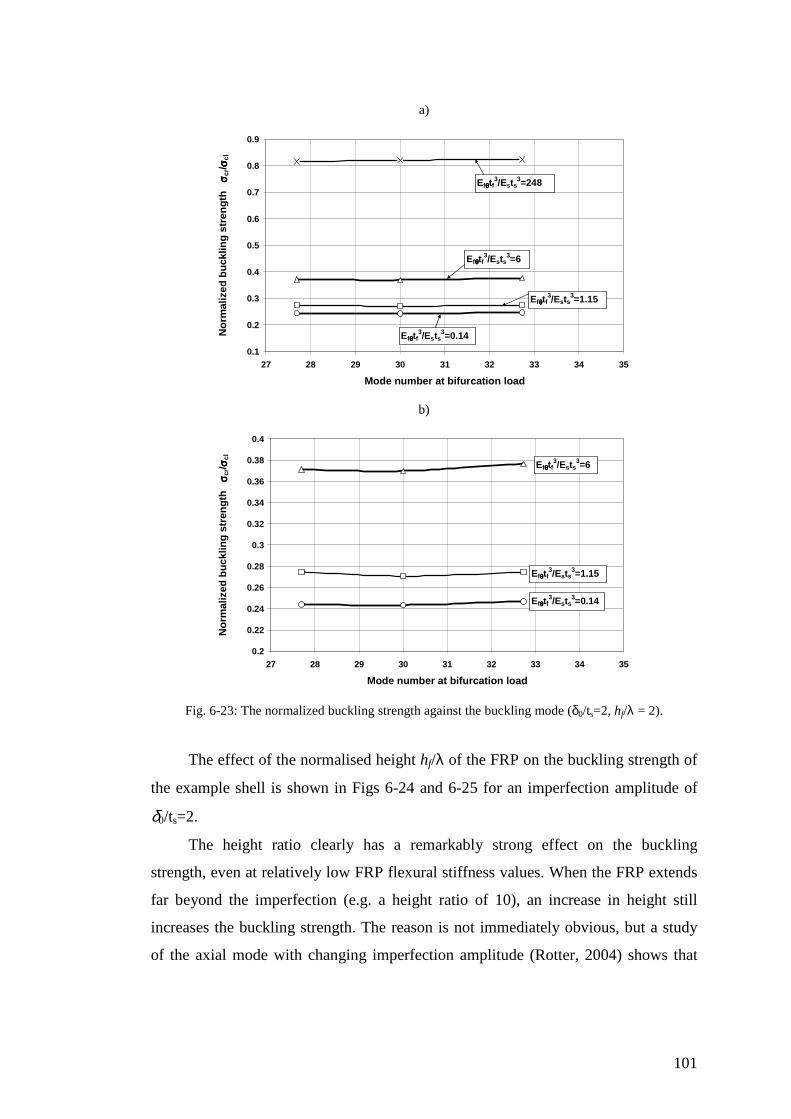
101
a)
0.1
0.2
0.3
0.4
0.5
0.6
0.7
0.8
0.9
27 28 29 30 31 32 33 34 35
Mode number at bifurcation load
No
rmal
ized
bu
cklin
g s
tren
gth
σσ σσ c
r/ σσ σσcl
Efθθθθtf3/Ests
3=6
Efθθθθtf3/Ests
3=1.15
Efθθθθtf3/Ests
3=0.14
Efθθθθtf3/Ests
3=248
b)
0.2
0.22
0.24
0.26
0.28
0.3
0.32
0.34
0.36
0.38
0.4
27 28 29 30 31 32 33 34 35
Mode number at bifurcation load
No
rmal
ized
bu
cklin
g s
tren
gth
σσ σσ c
r/ σσ σσcl
Efθθθθtf3/Ests
3=6
Efθθθθtf3/Ests
3=1.15
Efθθθθtf3/Ests
3=0.14
Fig. 6-23: The normalized buckling strength against the buckling mode (δ0/ts=2, hf/λ = 2).
The effect of the normalised height hf/λ of the FRP on the buckling strength of
the example shell is shown in Figs 6-24 and 6-25 for an imperfection amplitude of
δ0/ts=2.
The height ratio clearly has a remarkably strong effect on the buckling
strength, even at relatively low FRP flexural stiffness values. When the FRP extends
far beyond the imperfection (e.g. a height ratio of 10), an increase in height still
increases the buckling strength. The reason is not immediately obvious, but a study
of the axial mode with changing imperfection amplitude (Rotter, 2004) shows that
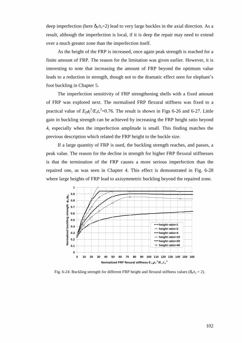
102
deep imperfection (here δ0/ts=2) lead to very large buckles in the axial direction. As a
result, although the imperfection is local, if it is deep the repair may need to extend
over a much greater zone than the imperfection itself.
As the height of the FRP is increased, once again peak strength is reached for a
finite amount of FRP. The reason for the limitation was given earlier. However, it is
interesting to note that increasing the amount of FRP beyond the optimum value
leads to a reduction in strength, though not to the dramatic effect seen for elephant’s
foot buckling in Chapter 5.
The imperfection sensitivity of FRP strengthening shells with a fixed amount
of FRP was explored next. The normalised FRP flexural stiffness was fixed to a
practical value of Efθtf3/Ests
3=0.76. The result is shown in Figs 6-26 and 6-27. Little
gain in buckling strength can be achieved by increasing the FRP height ratio beyond
4, especially when the imperfection amplitude is small. This finding matches the
previous description which related the FRP height to the buckle size.
If a large quantity of FRP is used, the buckling strength reaches, and passes, a
peak value. The reason for the decline in strength for higher FRP flexural stiffnesses
is that the termination of the FRP causes a more serious imperfection than the
repaired one, as was seen in Chapter 4. This effect is demonstrated in Fig. 6-28
where large heights of FRP lead to axisymmetric buckling beyond the repaired zone.
0
0.1
0.2
0.3
0.4
0.5
0.6
0.7
0.8
0.9
1
0 10 20 30 40 50 60 70 80 90 100 110 120 130 140 150 160
Normalized FRP flexural stiffness E f θθθθ t f3 /E s t s
3
No
rmal
ized
bu
cklin
g s
tren
gth
σσ σσcr
/ σσ σσcl
height ratio=1height ratio=2height ratio=4height ratio=10height ratio=20height ratio=40
Fig. 6-24: Buckling strength for different FRP height and flexural stiffness values (δ0/ts = 2).
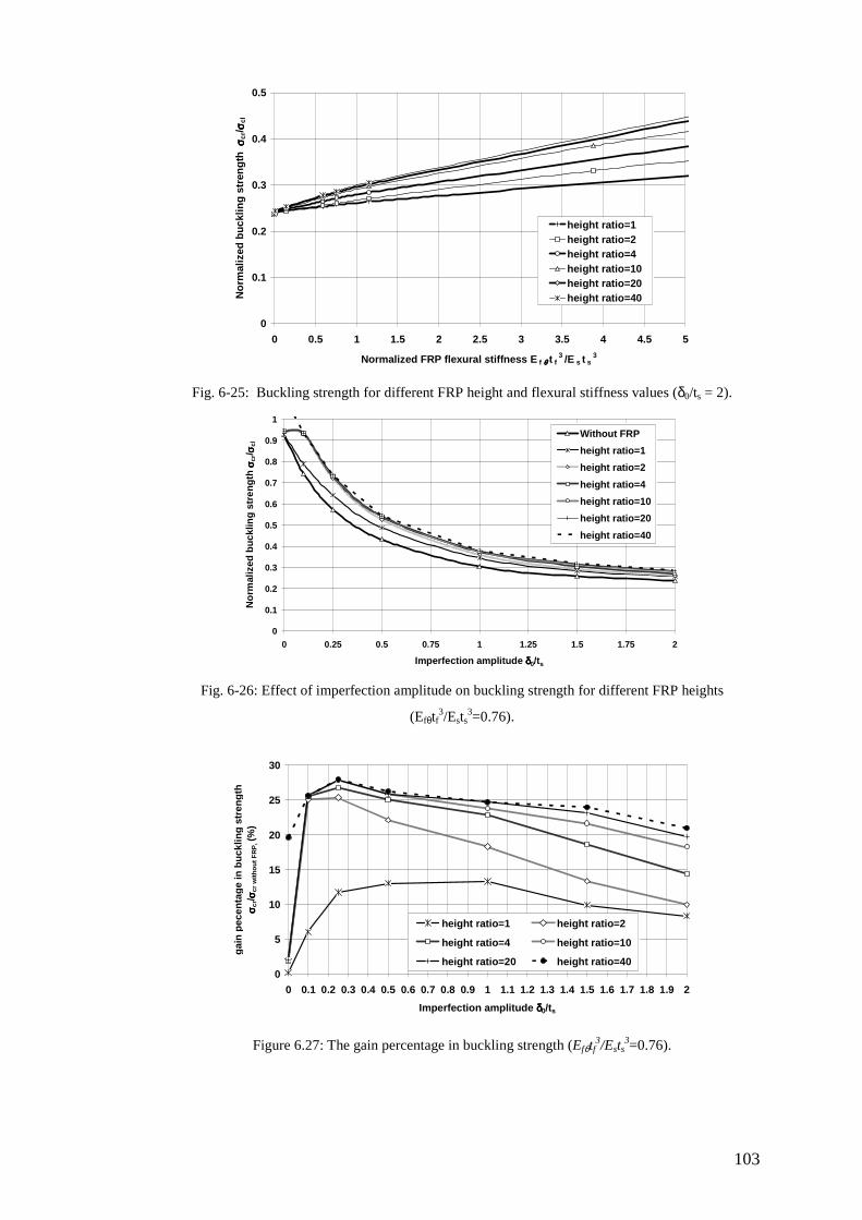
103
0
0.1
0.2
0.3
0.4
0.5
0 0.5 1 1.5 2 2.5 3 3.5 4 4.5 5
Normalized FRP flexural stiffness E f θθθθ t f3 /E s t s
3
No
rmal
ized
bu
cklin
g s
tren
gth
σσ σσcr
/ σσ σσcl
height ratio=1height ratio=2height ratio=4height ratio=10height ratio=20height ratio=40
Fig. 6-25: Buckling strength for different FRP height and flexural stiffness values (δ0/ts = 2).
0
0.1
0.2
0.3
0.4
0.5
0.6
0.7
0.8
0.9
1
0 0.25 0.5 0.75 1 1.25 1.5 1.75 2
Imperfection amplitude δδδδ0/ts
No
rmal
ized
bu
cklin
g s
tren
gth
σσ σσcr
/ σσ σσcl
Without FRP
height ratio=1
height ratio=2
height ratio=4
height ratio=10
height ratio=20
height ratio=40
Fig. 6-26: Effect of imperfection amplitude on buckling strength for different FRP heights
(Efθtf3/Ests
3=0.76).
0
5
10
15
20
25
30
0 0.1 0.2 0.3 0.4 0.5 0.6 0.7 0.8 0.9 1 1.1 1.2 1.3 1.4 1.5 1.6 1.7 1.8 1.9 2
Imperfection amplitude δδδδ0/ts
gai
n p
ecen
tag
e in
bu
cklin
g s
tren
gth
σσ σσ c
r/ σσ σσcr
wit
ho
ut
FR
P, (
%)
height ratio=1 height ratio=2
height ratio=4 height ratio=10
height ratio=20 height ratio=40
Figure 6.27: The gain percentage in buckling strength (Efθtf3/Ests
3=0.76).

104
0
2
4
6
8
10
12
14
16
18
20
-0.3 -0.2 -0.1 0 0.1 0.2 0.3Normalized radial displacement wr/ts
No
rmal
ized
dis
tan
se a
bo
ve t
he
mid
len
gth
z/ λλ λλ
hf/Lamda=20
hf/Lamda=32
Figure 6.28: Buckling displacements for different height ratio (Efθtf3/Ests
3=73.6 and δ0/ts=2).
6.5 Summary
This chapter has presented an initial study of the elastic buckling of FRP-
strengthened cylindrical shells with an axisymmetric local inward imperfection. The
buckling strength was calculated Using Geometrically Nonlinear Analysis with
Imperfections (GNIA). The effects of the amplitude of the imperfection, the FRP
stiffness and the FRP height were investigated. The results have shown that the
buckling strength can be significantly increased by bonding FRP within a zone that
relates to the size of the potential buckles, rather than to the zone of the imperfection.
It has shown that the thickness of the adhesive layer plays a more important role than
the amount of FRP and that an extensive zone of strengthening may be needed if the
local imperfection has a large amplitude. Nevertheless, the proposed technique could
be a very effective and economical method of strengthening shells that are too
imperfect to meet the tolerance limits required by EN 1993-1-6 (2007).

105
Chapter 7
Using FRP in strengthening the elastic buckling of
thin metallic cylinders with a single local dent
7.1 Introduction
The greatest cause of concern in a thin metal cylinder is often the presence of a
single local deep dent. A single dent of this kind can cause the tolerance
requirements to be missed, even though most of the shell is of good quality. Thus
strengthening a single dent by using FRP is potentially an extremely valuable and
cost-effective remedial measure.
This chapter addresses the strengthening of a cylindrical shell with a single
local dent against elastic buckling. Very few studies have explored the effect of a
single local dent in a cylinder, though such an imperfection may easily be produced
either during construction or in service as a result of an accidental impact.
The problem is explored using a Geometrically Nonlinear Analysis with
Imperfections (GNIA).
An extended detailed study is performed of the strength of thin cylindrical
shells with local dents of different sizes, shapes and depths. This study of the
buckling of unstrengthened isotropic cylinders is believed to be the first of its kind,
and is performed to identify the most damaging forms of local dents. This study has
implications for tolerance measurement methods as well as for repair requirements.

106
The use of FRP to enhance the strength of a cylinder with a local dent is then
explored, with a focus on the use of small quantities of FRP placed strategically to
achieve the best results.
Finally, a summary of the work of this chapter is given.
7.2 Finite element analysis procedures
7.2.1 Geometry, boundary conditions, material properties and loading
An example cylindrical shell with the following properties was used in this
study. The shell had a height h=3000mm, radius R=1000mm and constant thickness
ts=1mm. This gives a radius to thickness ratio of R/t=1000, and corresponds to a
medium length cylinder according to Eurocode 3 Part 1.6 (2007). The shell was
assumed to be made of an isotropic metal with Young’s modulus Es=200 GPa and
Poisson’s ratio νs = 0.3. The shell was subjected to a uniform axial load, resulting in
a uniform compressive membrane stress σz throughout the shell. The boundary
conditions at both ends were free in all directions except for both rotation about the
circumference and the circumferential displacement. These boundary conditions
correspond to a shell that continues far beyond the boundary.
To define the assumed imperfection, the vertical coordinate z was taken with
its origin at the mid-height of the shell. The imperfection was taken as a single
rectangular inward dent centred at the origin and of the form:
)]/cos()][/cos([ //0 θ
ππ ππδδ θ LyeLze Lyz
Lz z −−= (7-1)
in which δ is the local radial deviation from the perfect cylindrical shape at (θ, z),
δ0 is the characterising amplitude of the imperfection (value at the centre of the dent),
y is the circumferential coordinate from the centre of the dent with y=Rθ, Lz is the
half wavelength characterising the height and Lθ the half wavelength characterising
the width of the rectangular dent. The dent of Eq. 7-1 extends indefinitely, leading to
smooth transitions between the local dent and the remaining perfect shell.
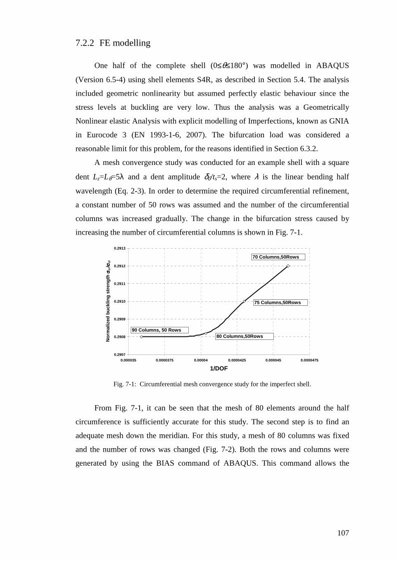
107
7.2.2 FE modelling
One half of the complete shell (0≤θ≤180°) was modelled in ABAQUS
(Version 6.5-4) using shell elements S4R, as described in Section 5.4. The analysis
included geometric nonlinearity but assumed perfectly elastic behaviour since the
stress levels at buckling are very low. Thus the analysis was a Geometrically
Nonlinear elastic Analysis with explicit modelling of Imperfections, known as GNIA
in Eurocode 3 (EN 1993-1-6, 2007). The bifurcation load was considered a
reasonable limit for this problem, for the reasons identified in Section 6.3.2.
A mesh convergence study was conducted for an example shell with a square
dent Lz=Lθ=5λ and a dent amplitude δ0/ts=2, where λ is the linear bending half
wavelength (Eq. 2-3). In order to determine the required circumferential refinement,
a constant number of 50 rows was assumed and the number of the circumferential
columns was increased gradually. The change in the bifurcation stress caused by
increasing the number of circumferential columns is shown in Fig. 7-1.
0.2907
0.2908
0.2909
0.2910
0.2911
0.2912
0.2913
0.000035 0.0000375 0.00004 0.0000425 0.000045 0.0000475
1/DOF
No
rmal
ized
bu
cklin
g s
tren
gth
σσ σσcr
/ σσ σσcl
90 Columns, 50 Rows80 Columns,50Rows
70 Columns,50Rows
75 Columns,50Rows
Fig. 7-1: Circumferential mesh convergence study for the imperfect shell.
From Fig. 7-1, it can be seen that the mesh of 80 elements around the half
circumference is sufficiently accurate for this study. The second step is to find an
adequate mesh down the meridian. For this study, a mesh of 80 columns was fixed
and the number of rows was changed (Fig. 7-2). Both the rows and columns were
generated by using the BIAS command of ABAQUS. This command allows the
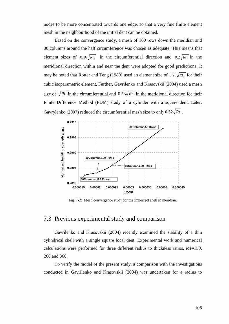
108
nodes to be more concentrated towards one edge, so that a very fine finite element
mesh in the neighbourhood of the initial dent can be obtained.
Based on the convergence study, a mesh of 100 rows down the meridian and
80 columns around the half circumference was chosen as adequate. This means that
element sizes of sRt16.0 in the circumferential direction and sRt2.0 in the
meridional direction within and near the dent were adopted for good predictions. It
may be noted that Rotter and Teng (1989) used an element size of sRt25.0 for their
cubic isoparametric element. Further, Gavrilenko and Krasovskii (2004) used a mesh
size of Rt in the circumferential and Rt53.0 in the meridional direction for their
Finite Difference Method (FDM) study of a cylinder with a square dent. Later,
Gavrylenko (2007) reduced the circumferential mesh size to only Rt52.0 .
0.2890
0.2895
0.2900
0.2905
0.2910
0.000015 0.00002 0.000025 0.00003 0.000035 0.00004 0.000045
1/DOF
No
rmal
ized
bu
cklin
g s
tren
gth
σσ σσcr
/ σσ σσcl
80Columns,120 Rows
80Columns,100 Rows
80Columns,50 Rows
80Columns,80 Rows
Fig. 7-2: Mesh convergence study for the imperfect shell in meridian.
7.3 Previous experimental study and comparison
Gavrilenko and Krasovskii (2004) recently examined the stability of a thin
cylindrical shell with a single square local dent. Experimental work and numerical
calculations were performed for three different radius to thickness ratios, R/t=150,
260 and 360.
To verify the model of the present study, a comparison with the investigations
conducted in Gavrilenko and Krasovskii (2004) was undertaken for a radius to

109
thickness ratio of 360. A cylindrical metal shell with radius R of 1000 mm and
thickness ts of 2.78 mm was studied with Young’s modulus Es of 191GPa and
Poisson’s ratio νs of 0.32 (these were the values reported by Gavrilenko and
Krasovskii (2004)). The boundary conditions at both ends were chosen as simple
supports, except for free displacement in the axial direction. Different square dent
dimensions, Lsq, were considered as shown in Table 7-1. The bifurcation buckling
strength of the cylindrical shell was calculated for four different imperfection forms
identified here by 2D-A for the 2D Type A form (Eq. 7-2), HC for the bi-directional
half cosine form (Eq. 7-3), CB for the complete chequerboard square pattern all over
the shell (Eq. 7-4) and Gav for the pattern chosen by Gavrylenko (2007) (Eq. 7-5).
)]/cos()][/cos([ //0 sq
Ly
sq
Lz LyeLze sqsq ππδδ ππ −−= (7-2)
)/cos()/cos(0 sqsq LyLz ππδδ = with
≤≤−
≤≤−
22
22sqsq
sqsq
Ly
L
Lz
L
(7-3)
)/cos()/cos(0 sqsq LyLz ππδδ = (7-4)
[ ])/3cos()/cos()/cos(0 sqsqsq LyLyLz πππδδ −= with
≤≤−
≤≤−
22
22sqsq
sqsq
Ly
L
Lz
L
(7-5)
Table 7-1: The dimensions of the local single square dent
Normalized initial dent depth, δ0/ts Normalized dent dimension, Lsq/λ
0.2 2.15 0.3 2.15
0.4 2.15
0.8 2.15
2 3
The buckling strengths calculated as part of this verification are shown in Fig.
7-3, where σcl is the classical buckling stress (Eq. 2-1).

110
0
0.1
0.2
0.3
0.4
0.5
0.6
0.7
0.8
0.9
1
0 0.2 0.4 0.6 0.8 1 1.2 1.4 1.6 1.8 2Normalized the intitial depth of dent δδδδ0/ts
No
rmal
ized
bu
cklin
g s
tren
gth
σσ σσcr
/ σσ σσcl
Gavrilenko and Krasovskii (2004)-Experiment
Gavrylenko (2007)-FDM analysis
Gavrilenko and Krasovskii (2004)-FDM analysis
2D-AHC
CB
Gav
Fig. 7-3: Variation of buckling strength with different dent dimensions.
No single analysis gives a good match to the experiments, especially at small
imperfection amplitudes: this suggests that either the tests were affected by other
imperfections (e.g. non-uniform loading on the boundary) or that the description of
the imperfection is incomplete.
The two finite difference calculation of Gavrilenko and Krasovskii (2004) and
Gavrylenko (2007) are quite different, and neither match the current finite element
predictions using their imperfection form. It may be that their finite element
difference meshes were not sufficiently refined, but it is difficult to verify this idea.
As may be expected, the chequerboard imperfection CB all over the shell gives
the lowest strengths. The half cosine HC gives lower strength than the two
dimensional weld depression 2D-A, and this may be caused by the extended zone of
deep dent given by a cos curve, coupled with the abrupt changes of slope
(discontinuities) at its edges. It is unclear whether this can be as a realistic
imperfection form.
The buckling strength of the FE analysis of the present study using the 2D-A
dent shape is in much closer agreement with the test results than the three others.
Although the shell strength of HC and CB forms is lower than the 2D-A form, it
appears that these two dent forms probably cannot easily occur in practical
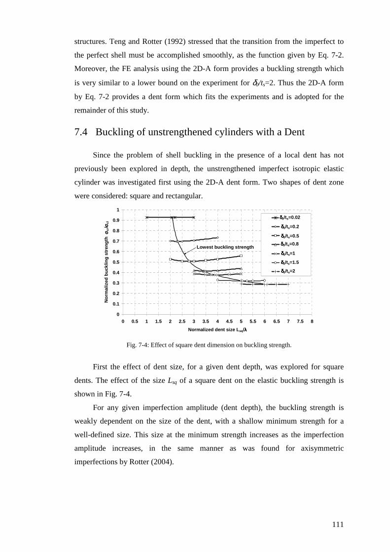
111
structures. Teng and Rotter (1992) stressed that the transition from the imperfect to
the perfect shell must be accomplished smoothly, as the function given by Eq. 7-2.
Moreover, the FE analysis using the 2D-A form provides a buckling strength which
is very similar to a lower bound on the experiment for δ0/ts=2. Thus the 2D-A form
by Eq. 7-2 provides a dent form which fits the experiments and is adopted for the
remainder of this study.
7.4 Buckling of unstrengthened cylinders with a Dent
Since the problem of shell buckling in the presence of a local dent has not
previously been explored in depth, the unstrengthened imperfect isotropic elastic
cylinder was investigated first using the 2D-A dent form. Two shapes of dent zone
were considered: square and rectangular.
0
0.1
0.2
0.3
0.4
0.5
0.6
0.7
0.8
0.9
1
0 0.5 1 1.5 2 2.5 3 3.5 4 4.5 5 5.5 6 6.5 7 7.5 8
Normalized dent size Lsq/λλλλ
No
rmal
ized
bu
cklin
g s
tren
gth
σσ σσcr
/ σσ σσcl
d0/t=0.02
d0/t=0.2
d0/t=0.5
d0/t=0.8
d0/t=1
d0/t=1.5
d0/t=2
δδδδ0/ts=0.2
δδδδ0/ts=0.5
δδδδ0/ts=0.8
δδδδ0/ts=1
δδδδ0/ts=1.5
δδδδ0/ts=2
Lowest buckling strength
δδδδ0/ts=0.02
Fig. 7-4: Effect of square dent dimension on buckling strength.
First the effect of dent size, for a given dent depth, was explored for square
dents. The effect of the size Lsq of a square dent on the elastic buckling strength is
shown in Fig. 7-4.
For any given imperfection amplitude (dent depth), the buckling strength is
weakly dependent on the size of the dent, with a shallow minimum strength for a
well-defined size. This size at the minimum strength increases as the imperfection
amplitude increases, in the same manner as was found for axisymmetric
imperfections by Rotter (2004).
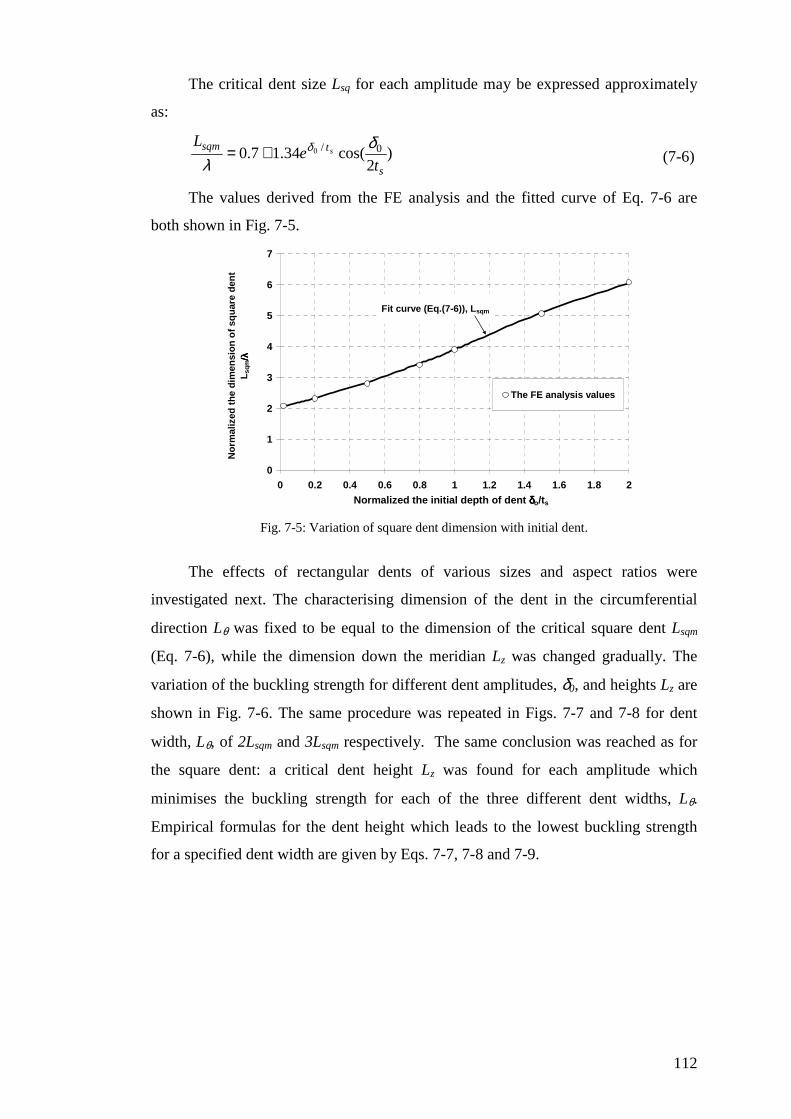
112
The critical dent size Lsq for each amplitude may be expressed approximately
as:
)2
cos(34.17.0 0/0
s
tsqm
te
Ls
δλ
δ+= (7-6)
The values derived from the FE analysis and the fitted curve of Eq. 7-6 are
both shown in Fig. 7-5.
0
1
2
3
4
5
6
7
0 0.2 0.4 0.6 0.8 1 1.2 1.4 1.6 1.8 2
Normalized the initial depth of dent δδδδo/ts
No
rmal
ized
th
e d
imen
sio
n o
f sq
uar
e d
ent
L
sqm
/λ/λ /λ/λ
The FE analysis values
Fit curve (Eq.(7-6)), Lsqm
Fig. 7-5: Variation of square dent dimension with initial dent.
The effects of rectangular dents of various sizes and aspect ratios were
investigated next. The characterising dimension of the dent in the circumferential
direction Lθ was fixed to be equal to the dimension of the critical square dent Lsqm
(Eq. 7-6), while the dimension down the meridian Lz was changed gradually. The
variation of the buckling strength for different dent amplitudes, δ0, and heights Lz are
shown in Fig. 7-6. The same procedure was repeated in Figs. 7-7 and 7-8 for dent
width, Lθ, of 2Lsqm and 3Lsqm respectively. The same conclusion was reached as for
the square dent: a critical dent height Lz was found for each amplitude which
minimises the buckling strength for each of the three different dent widths, Lθ.
Empirical formulas for the dent height which leads to the lowest buckling strength
for a specified dent width are given by Eqs. 7-7, 7-8 and 7-9.
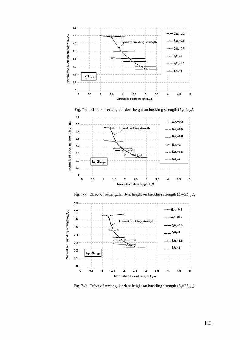
113
Lθθθθ=Lsqm
0
0.1
0.2
0.3
0.4
0.5
0.6
0.7
0.8
0 0.5 1 1.5 2 2.5 3 3.5 4 4.5 5
Normalized dent height Lz/λλλλ
No
rmal
ized
bu
cklin
g s
tren
gth
σσ σσcr
/ σσ σσcl d0/t=0.2
s0/t=0.5
d0/t=0.8
d0/t=1
d0/t=1.5
d0/t=2
δδδδ0/ts=0.2
δδδδ0/ts=0.5
δδδδ0/ts=0.8
δδδδ0/ts=1
δδδδ0/ts=1.5
δδδδ0/ts=2
Lowest buckling strength
Fig. 7-6: Effect of rectangular dent height on buckling strength (Lθ=Lsqm).
Lθθθθ=2Lsqm
0
0.1
0.2
0.3
0.4
0.5
0.6
0.7
0.8
0 0.5 1 1.5 2 2.5 3 3.5 4 4.5 5
Normalized dent height Lz/λλλλ
No
rmal
ized
bu
cklin
g s
tren
gth
σσ σσcr
/ σσ σσcl d0/t=0.2
s0/t=0.5
d0/t=0.8
d0/t=1
d0/t=1.5
d0/t=2
δδδδ0/ts=0.2
δδδδ0/ts=0.5
δδδδ0/ts=0.8
δδδδ0/ts=1
δδδδ0/ts=1.5
δδδδ0/ts=2
Lowest buckling strength
Fig. 7-7: Effect of rectangular dent height on buckling strength (Lθ=2Lsqm).
Lθθθθ=3Lsqm
0
0.1
0.2
0.3
0.4
0.5
0.6
0.7
0.8
0 0.5 1 1.5 2 2.5 3 3.5 4 4.5 5
Normalized dent height Lz/λλλλ
No
rmal
ized
bu
cklin
g s
tren
gth
σσ σσcr
/ σσ σσcl d0/t=0.2
s0/t=0.5
d0/t=0.8
d0/t=1
d0/t=1.5
d0/t=2
δδδδ0/ts=0.2
δδδδ0/ts=0.5
δδδδ0/ts=0.8
δδδδ0/ts=1
δδδδ0/ts=1.5
δδδδ0/ts=2
Lowest buckling strength
Fig. 7-8: Effect of rectangular dent height on buckling strength (Lθ=3Lsqm).

114
stz eL
09.0
3.24.3
δ
λ
−−= For Lθ=Lsqm (7-7)
stz eL
03.0
6.37.4
δ
λ
−−= For Lθ=2Lsqm (7-8)
stz eL
03.0
3.336.4
δ
λ
−−= For Lθ=3Lsqm (7-9)
The critical dent dimensions given by Eqs 7-7, 7-8 and 7-9 lead to buckling modes
corresponding to the Koiter circle (Fig. 7-9), (Koiter, 1945; Calladine, 1983;
Spagnoli, 2003).
Both the FE analysis values and the empirical fit curves of Eqs 7-7, 7-8 and 7-9
are shown in Fig. 7-10. In addition, the minimum buckling strength for each case of
changing Lθ is demonstrated in Fig. 7-11.
Fig. 7-9: Koiter circle for axially compressed cylindrical shell (Spagnoli, 2003).
0
0.5
1
1.5
2
2.5
3
3.5
4
0 0.2 0.4 0.6 0.8 1 1.2 1.4 1.6 1.8 2Normalized initial depth of dent δδδδo/ts
No
rmal
ized
axi
al d
imen
sio
n o
f re
ctan
gu
lar
den
t L
z /λ/λ /λ/λ
The FE analysis values, Lq=Lsqm
The FE analysis Values, Lq=2Lsqm
The FE analysis Values, Lq=3Lsqm
Fit curve (Eq.(7-7)), Lθθθθ=Lsqm
Fit curve (Eq.(7-8)), Lθθθθ=2Lsqm
Fit curve (Eq.(7-9)), Lθθθθ=3Lsqm
Lθθθθ=Lsqm
Lθθθθ=2Lsqm
Lθθθθ=3Lsqm
Fig. 7-10: Variation of axial dimension of dent with initial depth.
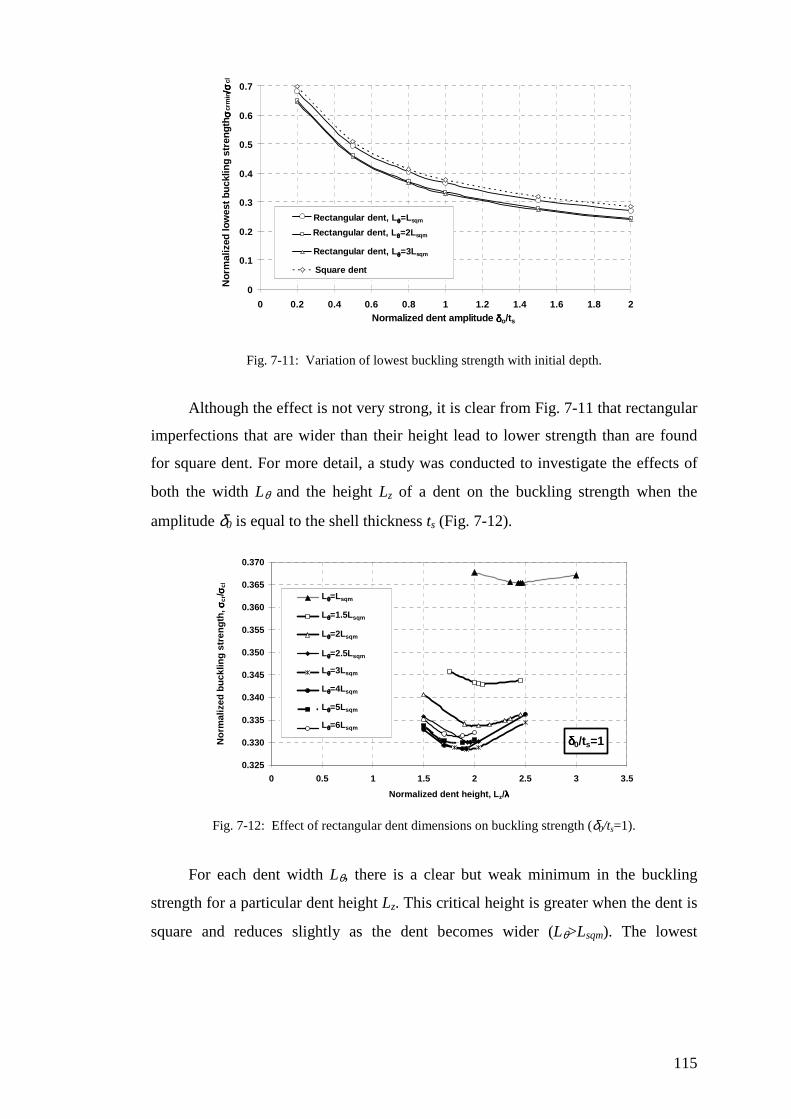
115
0
0.1
0.2
0.3
0.4
0.5
0.6
0.7
0 0.2 0.4 0.6 0.8 1 1.2 1.4 1.6 1.8 2Normalized dent amplitude δδδδo/ts
Nor
mal
ized
low
est
buck
ling
stre
ngt
h σσ σσ
crm
in/σ/σ /σ/σ
clRectangular dent Lc=Lsqm
rectangular dent Lc=2Lsqm
rectangulare dent Lc=3Lsqm
Square dent
Rectangular dent, Lθθθθ=Lsqm
Rectangular dent, Lθθθθ=2Lsqm
Rectangular dent, Lθθθθ=3Lsqm
Fig. 7-11: Variation of lowest buckling strength with initial depth.
Although the effect is not very strong, it is clear from Fig. 7-11 that rectangular
imperfections that are wider than their height lead to lower strength than are found
for square dent. For more detail, a study was conducted to investigate the effects of
both the width Lθ and the height Lz of a dent on the buckling strength when the
amplitude δ0 is equal to the shell thickness ts (Fig. 7-12).
δδδδ0/ts=1
0.325
0.330
0.335
0.340
0.345
0.350
0.355
0.360
0.365
0.370
0 0.5 1 1.5 2 2.5 3 3.5
Normalized dent height, Lz/λλλλ
No
rmal
ized
bu
cklin
g s
tren
gth
, σσ σσcr
/ σσ σσcl
Lq=Lsqm
Lq=1.5Lsqm
Lq=2Lsqm
Lq=2.5Lsqm
Lq=3Lsqm
Lq=4Lsqm
Lq=5Lsqm
Lq=6Lsqm
Lθθθθ=Lsqm
Lθθθθ=1.5Lsqm
Lθθθθ=2Lsqm
Lθθθθ=2.5Lsqm
Lθθθθ=3Lsqm
Lθθθθ=4Lsqm
Lθθθθ=5Lsqm
Lθθθθ=6Lsqm
Fig. 7-12: Effect of rectangular dent dimensions on buckling strength (δ0/ts=1).
For each dent width Lθ, there is a clear but weak minimum in the buckling
strength for a particular dent height Lz. This critical height is greater when the dent is
square and reduces slightly as the dent becomes wider (Lθ>Lsqm). The lowest
116
strengths of all are found when the width is about Lθ=3Lsqm and the height about
Lz=1.9λ or Lz=0.5Lsqm. This minimum is clearly only valid for δ0/ts=1.0. The width
Lθ=3Lsqm is used in the remainder of the study as a critical width.
To verify the critical dimensions obtained above, comparison with the studies
of Jamal et al. (1999, 2003) and Wullschleger (2006) were made.
Jamal et al. (1999, 2003) assumed a dent shape as follows:
+
++= −
)cos()cos(
))1(cos()cos()cos(2
2)/2(
0
2
yzd
zdyzde
c
baLz z
βγγβ
βγβγγδδ (7-10)
in which:
β is the modal aspect ratio (axial wavelength to circumferential wavelength).
γ=n/(Rβ), where R and n are the cylinder radius and the number of waves in the
circumferential direction repectively.
da, db and dc are coefficients linked by a relation of :
da+db+dc=1 (7-11)
This imperfection shape was used to calculate imperfection sensitivity curves
for different values of da, db and dc satisfying Eq. 7-11.
The buckling strengths for different dent amplitudes are shown in Fig. 7-13
where they are compared with the critical shape for 2D-A imperfection found in the
present study (Eq. 7-1). The dent dimensions used for both the 2D-A imperfection
(Eq. 7-1) and Jamal et al. (1999, 2003) dent form (Eq. 7-10) were the critical values
(Lθ=3Lsqm, Lz=Eq. 7-9). The parameters β and γ were chosen to correspond to a
circumferential wave number of 29 for the buckling mode of the perfect cylinder
given by Eq. 7-12, (Yamaki, 1983; Rotter, 2004):
t
Rncl 909.0≈ (7-12)
where R and t are the radius and thickness for the cylinder respectively.
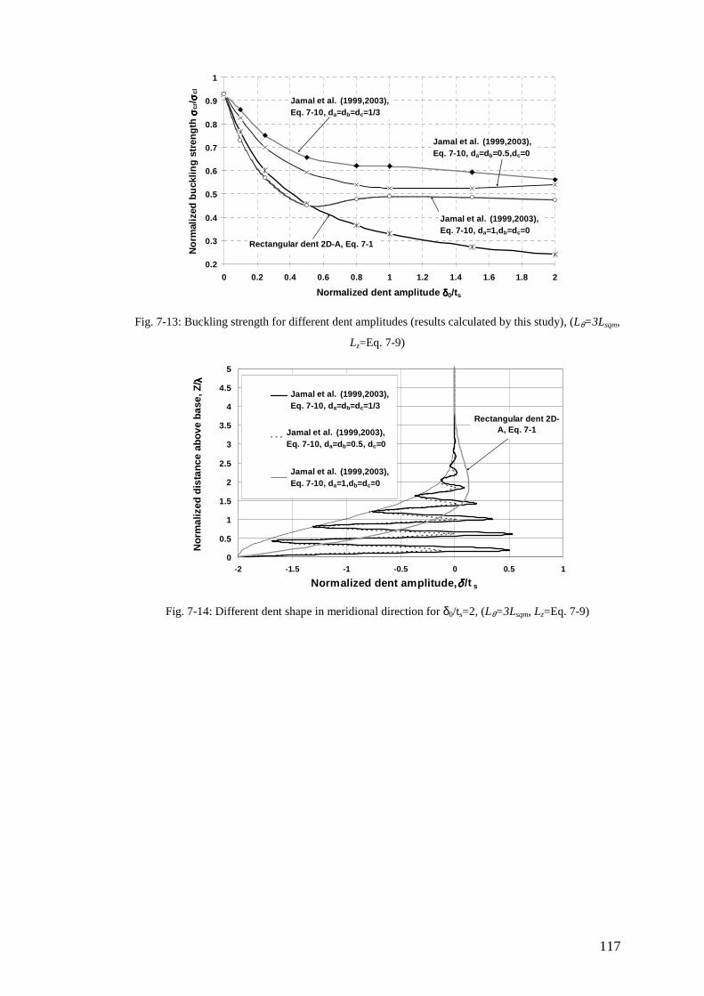
117
0.2
0.3
0.4
0.5
0.6
0.7
0.8
0.9
1
0 0.2 0.4 0.6 0.8 1 1.2 1.4 1.6 1.8 2
Normalized dent amplitude δδδδ0/ts
No
rmal
ized
bu
cklin
g s
tren
gth
σσ σσcr
/ σσ σσcl
Rectangular dent 2D-A, Eq. 7-1
Jamal et al. (1999,2003), Eq. 7-10, da=db=dc=1/3
Jamal et al. (1999,2003), Eq. 7-10, da=db=0.5,dc=0
Jamal et al. (1999,2003), Eq. 7-10, da=1,db=dc=0
Fig. 7-13: Buckling strength for different dent amplitudes (results calculated by this study), (Lθ=3Lsqm,
Lz=Eq. 7-9)
0
0.5
1
1.5
2
2.5
3
3.5
4
4.5
5
-2 -1.5 -1 -0.5 0 0.5 1
Normalized dent amplitude,δδδδ /t s
No
rmal
ized
dis
tan
ce a
bo
ve b
ase,
Z/ λλ λλ
Jamal, Da=db=dc=1/3
Jamal, da=db=0.5
Jamal, da=1
Jamal et al. (1999,2003), Eq. 7-10, da=db=dc=1/3
Jamal et al. (1999,2003), Eq. 7-10, da=db=0.5, dc=0
Jamal et al. (1999,2003), Eq. 7-10, da=1,db=dc=0
Rectangular dent 2D-A, Eq. 7-1
Fig. 7-14: Different dent shape in meridional direction for δ0/ts=2, (Lθ=3Lsqm, Lz=Eq. 7-9)
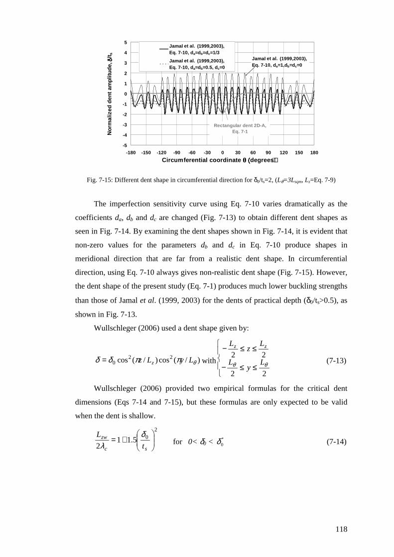
118
-5
-4
-3
-2
-1
0
1
2
3
4
5
-180 -150 -120 -90 -60 -30 0 30 60 90 120 150 180
Circumferential coordinate θ (θ (θ (θ (degrees))))
No
rmal
ized
den
t am
plit
ud
e, δδ δδ
/ts
Jamal, Da=db=dc=1/3
Jamal, da=db=0.5
Jamal et al. (1999,2003), Eq. 7-10, da=db=dc=1/3
Jamal et al. (1999,2003), Eq. 7-10, da=db=0.5, dc=0
Jamal et al. (1999,2003), Eq. 7-10, da=1,db=dc=0
Rectangular dent 2D-A, Eq. 7-1
Fig. 7-15: Different dent shape in circumferential direction for δ0/ts=2, (Lθ=3Lsqm, Lz=Eq. 7-9)
The imperfection sensitivity curve using Eq. 7-10 varies dramatically as the
coefficients da, db and dc are changed (Fig. 7-13) to obtain different dent shapes as
seen in Fig. 7-14. By examining the dent shapes shown in Fig. 7-14, it is evident that
non-zero values for the parameters db and dc in Eq. 7-10 produce shapes in
meridional direction that are far from a realistic dent shape. In circumferential
direction, using Eq. 7-10 always gives non-realistic dent shape (Fig. 7-15). However,
the dent shape of the present study (Eq. 7-1) produces much lower buckling strengths
than those of Jamal et al. (1999, 2003) for the dents of practical depth (δ0/ts>0.5), as
shown in Fig. 7-13.
Wullschleger (2006) used a dent shape given by:
)/(cos)/(cos 220 θππδδ LyLz z= with
≤≤−
≤≤−
22
22θθ L
yL
Lz
L zz
(7-13)
Wullschleger (2006) provided two empirical formulas for the critical dent
dimensions (Eqs 7-14 and 7-15), but these formulas are only expected to be valid
when the dent is shallow.
205.11
2
+=
sc
zw
t
L δλ for 0< δ0 < ∗
0δ (7-14)
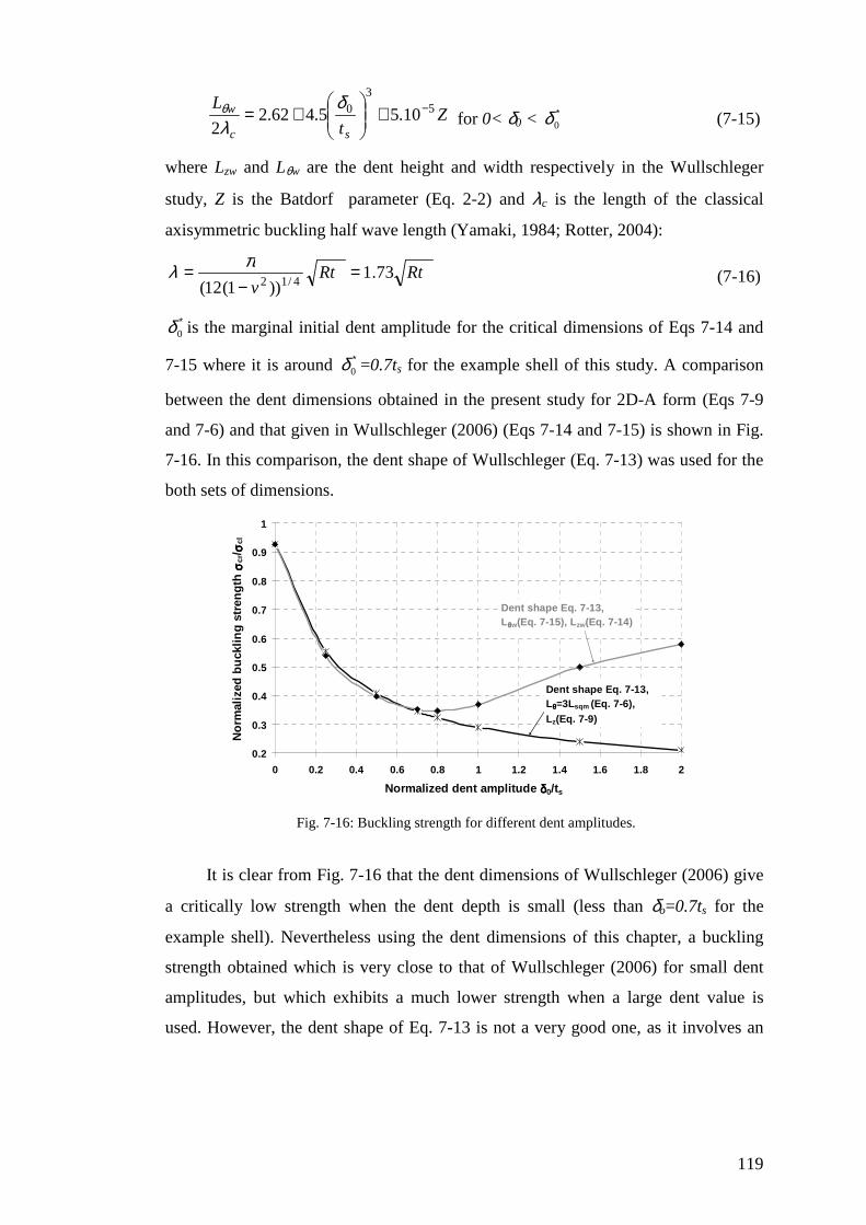
119
Zt
L
sc
w 53
0 10.55.462.22
−+
+=
δλθ
for 0< δ0 < ∗0δ (7-15)
where Lzw and Lθw are the dent height and width respectively in the Wullschleger
study, Z is the Batdorf parameter (Eq. 2-2) and λc is the length of the classical
axisymmetric buckling half wave length (Yamaki, 1984; Rotter, 2004):
RtRtv
73.1))1(12( 4/12
=−
= πλ (7-16)
∗0δ is the marginal initial dent amplitude for the critical dimensions of Eqs 7-14 and
7-15 where it is around ∗0δ =0.7ts for the example shell of this study. A comparison
between the dent dimensions obtained in the present study for 2D-A form (Eqs 7-9
and 7-6) and that given in Wullschleger (2006) (Eqs 7-14 and 7-15) is shown in Fig.
7-16. In this comparison, the dent shape of Wullschleger (Eq. 7-13) was used for the
both sets of dimensions.
0.2
0.3
0.4
0.5
0.6
0.7
0.8
0.9
1
0 0.2 0.4 0.6 0.8 1 1.2 1.4 1.6 1.8 2
Normalized dent amplitude δδδδ0/ts
No
rmal
ized
bu
cklin
g s
tren
gth
σσ σσcr
/ σσ σσcl
Dent shape Eq. 7-13, Lθθθθ=3Lsqm (Eq. 7-6), Lz(Eq. 7-9)
Dent shape Eq. 7-13, Lθθθθw(Eq. 7-15), Lzw(Eq. 7-14)
Fig. 7-16: Buckling strength for different dent amplitudes.
It is clear from Fig. 7-16 that the dent dimensions of Wullschleger (2006) give
a critically low strength when the dent depth is small (less than δo=0.7ts for the
example shell). Nevertheless using the dent dimensions of this chapter, a buckling
strength obtained which is very close to that of Wullschleger (2006) for small dent
amplitudes, but which exhibits a much lower strength when a large dent value is
used. However, the dent shape of Eq. 7-13 is not a very good one, as it involves an
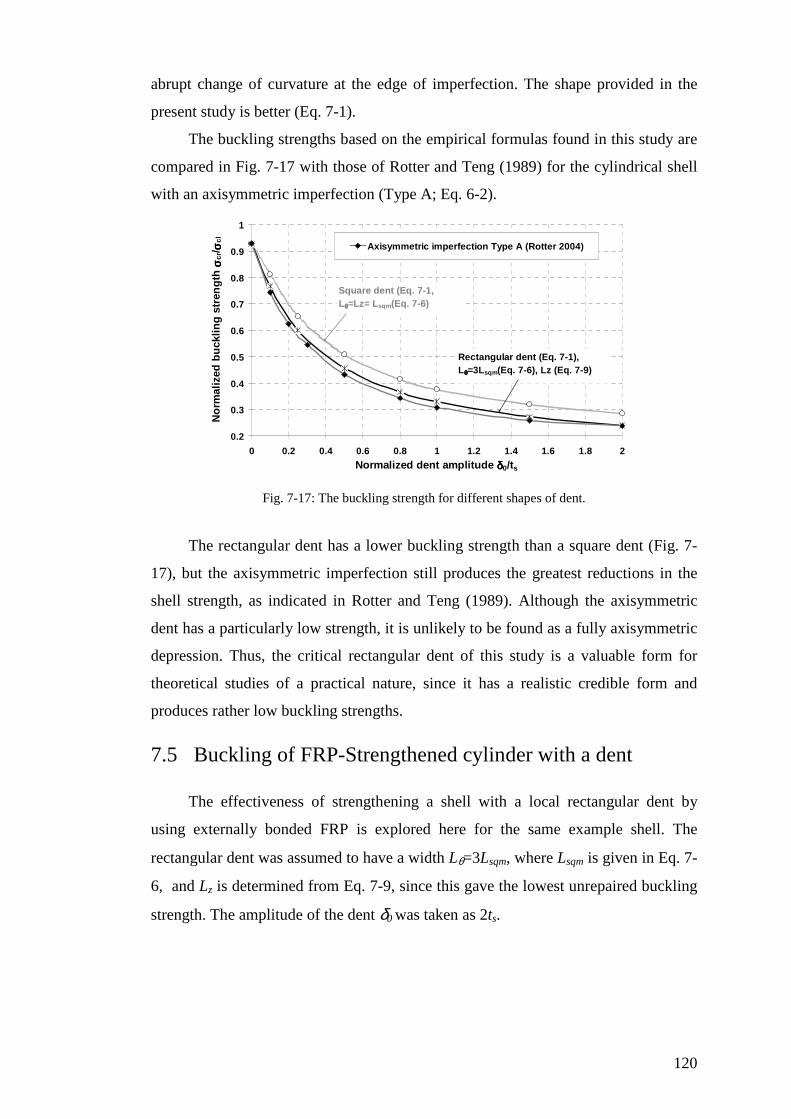
120
abrupt change of curvature at the edge of imperfection. The shape provided in the
present study is better (Eq. 7-1).
The buckling strengths based on the empirical formulas found in this study are
compared in Fig. 7-17 with those of Rotter and Teng (1989) for the cylindrical shell
with an axisymmetric imperfection (Type A; Eq. 6-2).
0.2
0.3
0.4
0.5
0.6
0.7
0.8
0.9
1
0 0.2 0.4 0.6 0.8 1 1.2 1.4 1.6 1.8 2
Normalized dent amplitude δδδδ0/ts
No
rmal
ized
bu
cklin
g s
tren
gth
σσ σσcr
/ σσ σσcl
Axisymmetric imperfection Type A (Rotter 2004)
Square dent (Eq. 7-1, Lθθθθ=Lz= Lsqm(Eq. 7-6)
Rectangular dent (Eq. 7-1), Lθθθθ=3Lsqm(Eq. 7-6), Lz (Eq. 7-9)
Fig. 7-17: The buckling strength for different shapes of dent.
The rectangular dent has a lower buckling strength than a square dent (Fig. 7-
17), but the axisymmetric imperfection still produces the greatest reductions in the
shell strength, as indicated in Rotter and Teng (1989). Although the axisymmetric
dent has a particularly low strength, it is unlikely to be found as a fully axisymmetric
depression. Thus, the critical rectangular dent of this study is a valuable form for
theoretical studies of a practical nature, since it has a realistic credible form and
produces rather low buckling strengths.
7.5 Buckling of FRP-Strengthened cylinder with a dent
The effectiveness of strengthening a shell with a local rectangular dent by
using externally bonded FRP is explored here for the same example shell. The
rectangular dent was assumed to have a width Lθ=3Lsqm, where Lsqm is given in Eq. 7-
6, and Lz is determined from Eq. 7-9, since this gave the lowest unrepaired buckling
strength. The amplitude of the dent δ0 was taken as 2ts.
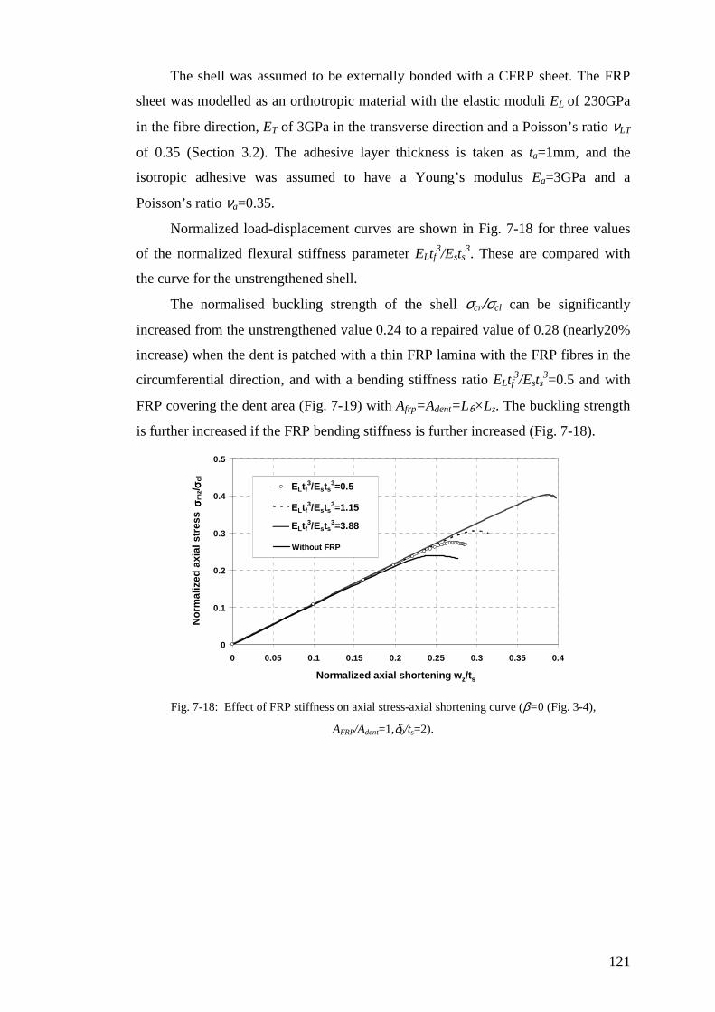
121
The shell was assumed to be externally bonded with a CFRP sheet. The FRP
sheet was modelled as an orthotropic material with the elastic moduli EL of 230GPa
in the fibre direction, ET of 3GPa in the transverse direction and a Poisson’s ratio νLT
of 0.35 (Section 3.2). The adhesive layer thickness is taken as ta=1mm, and the
isotropic adhesive was assumed to have a Young’s modulus Ea=3GPa and a
Poisson’s ratio νa=0.35.
Normalized load-displacement curves are shown in Fig. 7-18 for three values
of the normalized flexural stiffness parameter ELtf3/Ests
3. These are compared with
the curve for the unstrengthened shell.
The normalised buckling strength of the shell σcr/σcl can be significantly
increased from the unstrengthened value 0.24 to a repaired value of 0.28 (nearly20%
increase) when the dent is patched with a thin FRP lamina with the FRP fibres in the
circumferential direction, and with a bending stiffness ratio ELtf3/Ests
3=0.5 and with
FRP covering the dent area (Fig. 7-19) with Afrp=Adent=Lθ×Lz. The buckling strength
is further increased if the FRP bending stiffness is further increased (Fig. 7-18).
0
0.1
0.2
0.3
0.4
0.5
0 0.05 0.1 0.15 0.2 0.25 0.3 0.35 0.4
Normalized axial shortening wz/ts
No
rmal
ized
axi
al s
tres
s σσ σσ
mz/
σσ σσcl
Efqtf3/Ests3=0.5
Efqtf3/Ests3=1.15
Efqtf3/Ests3=3.88
Without FRP
ELtf3/Ests
3=0.5
ELtf3/Ests
3=1.15
ELtf3/Ests
3=3.88
Fig. 7-18: Effect of FRP stiffness on axial stress-axial shortening curve (β=0 (Fig. 3-4),
AFRP/Adent=1,δ0/ts=2).
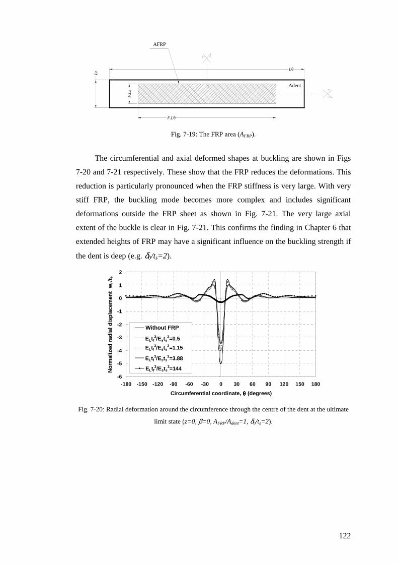
122
Lθ
Lz
F.Lθ
F.L
z
Adent
AFRP
Fig. 7-19: The FRP area (AFRP).
The circumferential and axial deformed shapes at buckling are shown in Figs
7-20 and 7-21 respectively. These show that the FRP reduces the deformations. This
reduction is particularly pronounced when the FRP stiffness is very large. With very
stiff FRP, the buckling mode becomes more complex and includes significant
deformations outside the FRP sheet as shown in Fig. 7-21. The very large axial
extent of the buckle is clear in Fig. 7-21. This confirms the finding in Chapter 6 that
extended heights of FRP may have a significant influence on the buckling strength if
the dent is deep (e.g. δ0/ts=2).
-6
-5
-4
-3
-2
-1
0
1
2
-180 -150 -120 -90 -60 -30 0 30 60 90 120 150 180
Circumferential coordinate, θθθθ (degrees)
No
rmal
ized
rad
ial d
isp
lace
men
t w
r/t s
Without FRP
eftf3/ests3=1/7
eftf3/ests=1.15
eftf3/ests3=3.88
eftf3/ests3=144
ELtf3/Ests
3=0.5
ELtf3/Ests
3=1.15
ELtf3/Ests
3=3.88
ELtf3/Ests
3=144
Fig. 7-20: Radial deformation around the circumference through the centre of the dent at the ultimate
limit state (z=0, β=0, AFRP/Adent=1, δ0/ts=2).
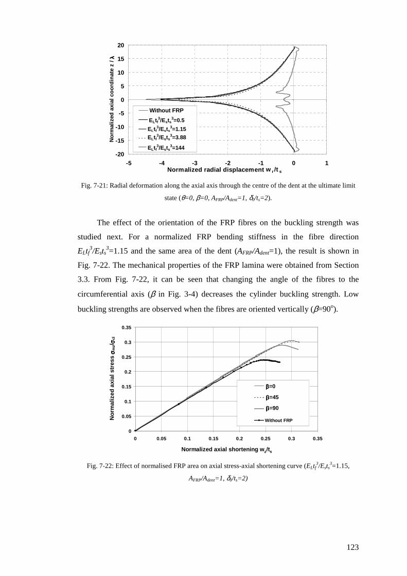
123
-20
-15
-10
-5
0
5
10
15
20
-5 -4 -3 -2 -1 0 1Normalized radial displacement w r /t s
No
rmal
ized
axi
al c
oo
rdin
ate
z /
λλ λλWithout FRP
eftf3/ests3=1/7
eftf3/ests=1.15
eftf3/ests3=3.88
eftf3/ests3=144
ELtf3/Ests
3=0.5
ELtf3/Ests
3=1.15
ELtf3/Ests
3=3.88
ELtf3/Ests
3=144
Fig. 7-21: Radial deformation along the axial axis through the centre of the dent at the ultimate limit
state (θ=0, β=0, AFRP/Adent=1, δ0/ts=2).
The effect of the orientation of the FRP fibres on the buckling strength was
studied next. For a normalized FRP bending stiffness in the fibre direction
ELtf3/Ests
3=1.15 and the same area of the dent (AFRP/Adent=1), the result is shown in
Fig. 7-22. The mechanical properties of the FRP lamina were obtained from Section
3.3. From Fig. 7-22, it can be seen that changing the angle of the fibres to the
circumferential axis (β in Fig. 3-4) decreases the cylinder buckling strength. Low
buckling strengths are observed when the fibres are oriented vertically (β=90o).
0
0.05
0.1
0.15
0.2
0.25
0.3
0.35
0 0.05 0.1 0.15 0.2 0.25 0.3 0.35
Normalized axial shortening wz/ts
No
rmal
ized
axi
al s
tres
s σσ σσ
mz/
σσ σσcl
Ez/Eq=1/77
Ez/Eq=1
Ez/Eq=77
Without FRP
ββββ=0
ββββ=45
ββββ=90
Fig. 7-22: Effect of normalised FRP area on axial stress-axial shortening curve (ELtf3/Ests
3=1.15,
AFRP/Adent=1, δ0/ts=2)
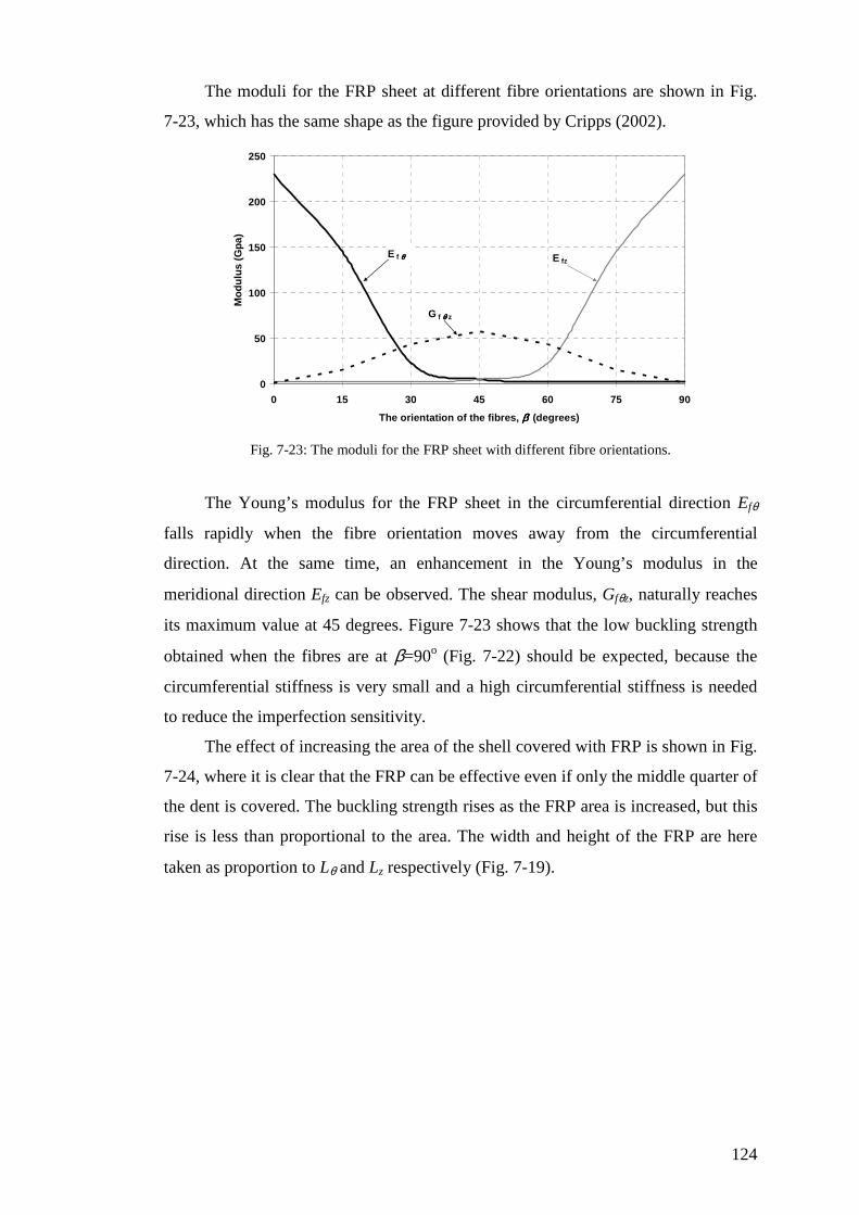
124
The moduli for the FRP sheet at different fibre orientations are shown in Fig.
7-23, which has the same shape as the figure provided by Cripps (2002).
0
50
100
150
200
250
0 15 30 45 60 75 90
The orientation of the fibres, ββββ (degrees)
Mo
du
lus
(Gp
a)
E f θθθθ E fz
G f θθθθ z
Fig. 7-23: The moduli for the FRP sheet with different fibre orientations.
The Young’s modulus for the FRP sheet in the circumferential direction Efθ
falls rapidly when the fibre orientation moves away from the circumferential
direction. At the same time, an enhancement in the Young’s modulus in the
meridional direction Efz can be observed. The shear modulus, Gfθz, naturally reaches
its maximum value at 45 degrees. Figure 7-23 shows that the low buckling strength
obtained when the fibres are at β=90o (Fig. 7-22) should be expected, because the
circumferential stiffness is very small and a high circumferential stiffness is needed
to reduce the imperfection sensitivity.
The effect of increasing the area of the shell covered with FRP is shown in Fig.
7-24, where it is clear that the FRP can be effective even if only the middle quarter of
the dent is covered. The buckling strength rises as the FRP area is increased, but this
rise is less than proportional to the area. The width and height of the FRP are here
taken as proportion to Lθ and Lz respectively (Fig. 7-19).

125
0
0.05
0.1
0.15
0.2
0.25
0.3
0.35
0 0.05 0.1 0.15 0.2 0.25 0.3 0.35
Normalized axial shortening wz/ts
No
rmal
ized
axi
al s
tres
s σσ σσ
mz/ σσ σσ
clAf/Ad=0.25
Af/ad=1
Af/Ad=4
Without FRP
AFRP/Adent=0.25
AFRP/Adent=1
AFRP/Adent=4
Fig. 7-24: Effect of normalised FRP area on axial stress-axial shortening curve (ELtf3/Ests
3=1.15, β=0,
δ0/ts=2)
To obtain a fuller picture, a more detailed study was undertaken. The buckling
strength is obtained (Fig. 7-25) for different FRP bending stiffnesses (αb=ELtf3/Ests
3)
and different fibre orientations (β) relative to the circumferential axis.
0.2
0.25
0.3
0.35
0.4
0.45
0.5
0.55
0.6
0 15 30 45 60 75 90
The orientation of FRP fibres,ββββ (degrees)
No
rmal
ized
bu
cklin
g s
tren
gth
σσ σσcr
/ σσ σσcl a=0
a=0.074
a=0.248
a=0.485
a=0.706
a=1.15
a=3.88
a=9.2
ααααb=0
ααααb=0.074
ααααb=0.248
ααααb=0.485
ααααb=0.706
ααααb=1.15
ααααb=3.88
ααααb=9.2
Fig. 7-25: The buckling strength for different FRP stiffnesses and different orientations (AFRP/Adent=1,
δ0/ts=2)
As expected, an increased FRP thickness enhances the buckling strength (Fig.
7-25). On the other hand, the fibre orientations affect the buckling axial load. For a
practical thin FRP thickness (αb<1.15), the buckling load is steadily reduced as the
orientation of the fibres changes from 0o to 90o. With a very stiff FRP sheet, the fibre
orientation around 30o registers the highest buckling strength. This increased strength
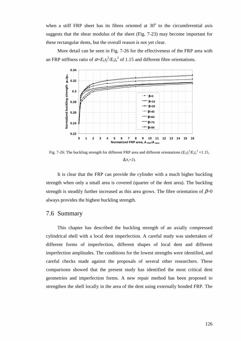
126
when a stiff FRP sheet has its fibres oriented at 30o to the circumferential axis
suggests that the shear modulus of the sheet (Fig. 7-23) may become important for
these rectangular dents, but the overall reason is not yet clear.
More detail can be seen in Fig. 7-26 for the effectiveness of the FRP area with
an FRP stiffness ratio of α=ELtf3/Ests
3 of 1.15 and different fibre orientations.
0.22
0.24
0.26
0.28
0.3
0.32
0.34
0 1 2 3 4 5 6 7 8 9 10 11 12 13 14 15 16Normalized FRP area, A FRP /A dent
No
rmal
ized
bu
cklin
g s
tren
gth
σσ σσcr
/ σσ σσcl
a=0
a=15
a=30
a=45
a=60
a=75
a=90
ββββ=0
ββββ=15
ββββ=30
ββββ=45
ββββ=60
ββββ=75
ββββ=90
Fig. 7-26: The buckling strength for different FRP area and different orientations (ELtf3/Ests
3 =1.15,
δ0/ts=2).
It is clear that the FRP can provide the cylinder with a much higher buckling
strength when only a small area is covered (quarter of the dent area). The buckling
strength is steadily further increased as this area grows. The fibre orientation of β=0
always provides the highest buckling strength.
7.6 Summary
This chapter has described the buckling strength of an axially compressed
cylindrical shell with a local dent imperfection. A careful study was undertaken of
different forms of imperfection, different shapes of local dent and different
imperfection amplitudes. The conditions for the lowest strengths were identified, and
careful checks made against the proposals of several other researchers. These
comparisons showed that the present study has identified the most critical dent
geometries and imperfection forms. A new repair method has been proposed to
strengthen the shell locally in the area of the dent using externally bonded FRP. The
127
effectiveness of this method has been explored numerically using Geometrically
Nonlinear Analysis with Imperfections (GNIA). For the worst rectangular dent, the
effects of the FRP flexural stiffness, fibre orientations and the FRP area have been
investigated. The results have shown that the buckling strength can be very
significantly enhanced by bonding a small amount FRP locally within the dent zone.

128
Chapter 8
Conclusions and recommendations
8.1 Summary
Many analyses of cylindrical shells have been performed in this thesis to
investigate the effectiveness of FRP composites to increase the buckling capacity of
thin metal cylindrical shells.
Two loading conditions were applied: uniform internal pressure accompanied
by axial load, and axial loads with geometric imperfections. The local imperfections
were divided into two categories: an inward axisymmetric imperfection and a local
dent imperfection. The imperfection amplitude was defined by the ratio δ0/ts where
δ0 is the imperfection depth at the centre of the imperfection and ts is the metal
thickness.
An analytical method was used first to derive the general equations governing
the linear elastic behaviour of an FRP-strengthened cylindrical shell under internal
pressure accompanied by axial force. Then, nonlinear finite element analysis was
performed, using the ABAQUS program, to obtain all the results involving non
linear analysis. The modified Riks routine (arc length technique) was used to trace all
the nonlinear paths.
The example cylinder used in all the example calculations was chosen to have
a radius to thickness ratio R/t of 1000 and corresponded to a medium- length
129
cylindrical shell. The metal cylinder was assumed to be made of an isotropic metal
with Young’s modulus Es of 200 GPa and Poisson’s ratio νs of 0.3. On the other
hand, the FRP sheet was treated as orthotropic, with Young’s modulus Efθ in the
circumferential direction, and Efz in the meridional direction with a Poisson’s ratio in
the circumferential direction, νfθ .
The enhancement of the buckling strength achieved by using the bonded FRP
was shown using the ratio of the axial stress at the buckling to the classical elastic
critical buckling stress σmx/σcl or σcr /σcl.
In this chapter, the conclusions obtained from each of the studied problems are
reviewed.
Finally, recommendations for future research work are suggested.
8.2 FRP preventing radial displacements in pressurized
cylinders, Linear elastic Analysis (LA)
Chapter 4 presented an initial linear elastic study of the strengthening of a
pressurized cylindrical shell using externally bonded FRP. The FRP sheet was
assumed to consist of uniaxial fibres in the circumferential direction.
The general linear elastic equations for the FRP-strengthened cylinder were
derived for both pinned base and fixed base boundary conditions.
Decreasing the radial displacement was the main concern in that chapter
because radial displacements are closely linked to the circumferential stresses, which
couple with the axial compression to cause premature failure by elephant’s foot
buckling.
The optimal FRP thickness tf and FRP height hf together with the optimal
starting point for the FRP sheet above the base xf were estimated for this purpose,
using the equations obtained in that chapter.
It was found that a small amount of FRP sheet centred on the location where
the radial displacement peaked in the unstrengthened cylinder is very effective in
reducing the maximum deflection near the base to the membrane theory deflection.
Moreover, both too little and too much FRP lead to higher radial deformations than
the optimal amount.
130
8.3 Strengthening cylindrical shells against elephant’s foot
buckling using FRP
In chapter 5, the stability of a metal cylinder under high internal pressure
accompanied with axial load was discussed.
Geometrically and Materially Nonlinear Analysis (GMNA) was used to study
the elastic-plastic collapse by elephant’s foot buckling of a simply supported metal
cylindrical shell where the stress strain curve was assumed to be perfectly elastic-
plastic with no hardening.
The analysis was done using the 2-node axisymmetric general-purpose shell
element (SAX1) and the finite element analysis program ABAQUS.
The effect of circumferential uniaxial-fibre FRP strengthening on the elastic-
plastic buckling strength of a cylinder of radius to thickness ratio R/t=1000 was
established. The valuable gain in buckling strength was achieved using a small
amount of FRP composite.
For the example cylinder, the optimal FRP thickness tf, FRP height hf and FRP
starting distance above the base xf were found with appropriate reference to the
fabrication quality classes of Eurocode3 Part1.6 (2007). The aim was to increase the
elastic-plastic collapse strength of the unstrengthened cylinder up to the limits of
membrane yield (von Mises) or the elastic imperfect buckling strength. Then,
empirical formulas for these three optimal FRP parameter values were produced.
It was shown clearly that if different values of the FRP parameters from the
optimal ones were chosen, the strength could be significantly reduced. Further, the
sensitivity of the buckling load to the starting distance xf for the FRP above the base
is much less than the sensitivity to the values of other two FRP parameters tf or hf.
Furthermore, the buckling strength is more sensitive to the FRP height hf than to the
FRP thickness tf in the membrane yield limit, whereas the reverse can be said for
elastic buckling conditions.
131
8.4 Elastic buckling of FRP-strengthened cylinders with
axisymmetric imperfections
Chapter 6 presented an initial study of the elastic buckling strength of an FRP-
strengthened cylindrical shell with an axisymmetric inward imperfection.
Under uniform axial load applied at the top of the cylinder and an imperfection
shape of weld Type A (Rotter and Teng, 1989), the strength obtained was limited by
the elastic bifurcation buckling.
The example cylinder was assumed to have a radius to thickness ratio of 1000,
and corresponds to a medium length cylinder with free boundary conditions, except
for both rotations about the circumference and the circumferential displacement.
This axisymmetric inward imperfection was placed at the mid-height of the
cylinder and the interaction between the neighbouring similar imperfections was
ignored.
Geometrically Nonlinear Analysis with Imperfections (GNIA) was undertaken
in this study using the finite element package ABAQUS and the modified Riks
method. The 4-node doubly curved thin shell element S4R was used to model first
the cylinder and then both the FRP and the adhesive in the next step.
The FRP was taken as uniaxial fibres in the circumferential direction. An
adhesive layer of finite thickness was assumed between the FRP and the metallic
cylinder. The adhesive layer was assumed to have isotropic properties with a low
modulus.
Because of the expected high participation of the bending stiffness in the
elastic buckling behaviour, the bending stiffness of the FRP sheet relative to that of
the metal shell Efθtf3/Ests
3 was used to explore the effectiveness of the FRP
strengthening in enhancing the buckling strength. It was shown that a significant gain
in buckling strength is obtained if this flexural stiffness is large. It was shown that
the increased buckling strength of an FRP repaired shell depends on the change of
flexural stiffness caused by the FRP, not the change in extensional stiffness. It was
also shown that a thick layer of adhesive is very beneficial in raising the buckling
strength, and this differs considerably from other applications of FRP to strengthen
structures.
132
The buckling strength was found to increase when the height of the zone
covered by the FRP is increased.
The study was extended to cover different imperfection amplitudes. In all
cases, the buckling strength was enhanced when FRP composites were applied, but
the FRP repair for elastic buckling was much less effective than its use to prevent
elastic-plastic collapse by elephant’s foot buckling. This conclusion was clear when
the imperfection was deep (e.g. δ0/t=2). The reason is that a circumferential FRP
sheet is very effective in resisting the circumferential tension caused by a high
internal pressure in the case of elephant’s foot buckling, but it is less effective when
an increase in the elastic buckling strength depends on achieving an increased
flexural stiffness.
Studies of changes in the height of the FRP sheet showed that the buckling
strength continued to rise even when the sheet extended for beyond the imperfection
(at least for deep imperfection). The reason was found in the shape of the bifurcation
mode, which has a large axial range for deep imperfections. This difference between
a repair covering the imperfection and a repair covering the buckling mode has not
been recognized before.
In conclusion, this study has shown that bonding FRP to the exterior of an
imperfect shell can be a new economical repairing technique, even when only a
relatively small zone is strengthened.
8.5 Using FRP in strengthening the elastic buckling of thin
metallic cylinders with a single local dent
In Chapter 7, the bifurcation buckling of a cylindrical shell with a single local
dent was studied first. The effectiveness of FRP strengthening to increase the
buckling strength was then explored.
The cylinder was subjected to a uniform axial load at the top. A cylinder of
radius to thickness ratio R/t of 1000 was chosen, corresponding to a medium length
cylinder with free boundary conditions, except for rotations about the circumference
and the circumferential displacement.
Geometrically Nonlinear Analysis with Imperfections (GNIA) was undertaken
using the finite element package ABAQUS and modified Riks method. The 4-node

133
doubly curved thin shell element S4R was used to model the metal cylinder first and
for both the FRP and adhesive in the next step.
A local single dent was studied at the mid-height of the cylinder and the
buckling strength was calculated for different shapes and sizes of this dent.
A 2D imperfection in a form similar to the Type A weld depression of Rotter
and Teng (1989) was chosen. When the buckling strength predictions were compared
with previously published test results, this imperfection was found to give a
reasonably satisfactory match. This imperfection has the advantage that no
discontinuities of slope or curvature occur at the edges of the imperfect zone. Such
discontinuities lead to high local stresses, so may be unrealistic.
Two shapes for dent zone were considered: square dent and rectangular dent.
The critical dent sizes which lead to the minimum buckling strength were obtained
for different dent amplitudes. Empirical formulas to represent these sizes were
derived.
It was shown that a rectangular dent with a width Lθ equal to 3Lsqm (where Lsqm
is the critical size of a square dent) produces the lowest buckling strength, but the
complete axisymmetric imperfection still causes the greatest reduction in the
bifurcation buckling strength of the shell.
The rectangular dent of width 3Lsqm and amplitude δ0/ts=2 was chosen to be
repaired, using an FRP lamina with Young’s modulus EL in the fibre direction and ET
in the transverse direction and Poisson’s ratio νLT. An isotropic adhesive layer was
installed between the FRP and metal.
The effects of the FRP stiffness, fibre orientation and FRP area were
investigated. It was shown that a thin FRP lamina increased the buckling strength
significantly. Fibres oriented in the circumferential direction provide a higher
buckling strength than other orientations for practical FRP thicknesses. The lowest
buckling strength was observed when the fibres were oriented vertically.
The elastic buckling strength of the cylinder was found to rise significantly
when the FRP area is increased. However, the FRP became effective even if only the
middle quarter of the dent was covered.
134
Thus, FRP composite material applied to a small zone at the centre of the dent
can provide a significant enhancement in strength. This is a new technique to raise
the elastic buckling strength of an imperfect cylinder.
8.6 Recommendations for future work
In this thesis, FRP composites have been used as a new technique to raise the
buckling strength of a cylindrical metal shell under two loading conditions: internal
pressure accompanied with axial load and uniform vertical load with imperfections.
Within the limited time available for this research, the studies have demonstrated that
FRP can be used effectively to enhance the stability of the cylindrical part of a steel
tank or silo, but the author believes that there are still some questions that should be
addressed. The following are some suggestions for future work.
In all the cases studied in this thesis, the cylinder radius to thickness ratio R/t
was 1000. Therefore, there is an important question about the effect of changing this
ratio. For example, in the case of elephant’s foot buckling under high internal
pressure, the elastic-plastic collapse strength changes when the radius to thickness
ratio is changed, so new optimal FRP dimensions need to be obtained by changing
this ratio. For the imperfect cylinder under axial load only, the buckling strength was
found by Rotter and Teng (1989) to be independent of the radius to thickness ratio.
However, the required amount of FRP to achieve a certain degree of strengthening
may depend on R/t.
This thesis dealt with the FRP sheet as one layer. It may be that useful gains
can be made using a layered FRP sheet with different fibre orientations for each
layer. The effectiveness of the adhesive between the FRP layers needs to be explored
as this can increase the flexural stiffness. It is clear that the final buckling strength
may be connected with a new FRP flexural stiffness related to the number of the
layers and the fibre orientation of each layer.
In Chapter 7, the fibre orientation was discussed without exploring the Efz/Efθ
ratio itself. Therefore, this question needs additional work to be answered from the
thinking that it will have a significant influence on the buckling strength.

135
In Chapter 7, the effectiveness of the FRP strengthening was studied, using one
imperfection amplitude of δ0/ts=2. This study certainly needs to be extended to
different imperfection amplitudes.
In this study, a continuous FRP sheet was bonded externally to the metal
cylinder. A useful question needs to be answered about the effect of non-continuous
FRP sheet. The effect of separated FRP strips on the buckling strength has not been
studied. Is it more economical than the continuous one? What are the distance limits
required between these strips for them to be effective?.
Finally, different load patterns, such as seismic loading, wind loading, external
pressure loading etc., could be usefully explored in future studies.

136
References
ABAQUS, Version 6.5-4 (2005). ABAQUS/Standard User’s Manual, ABAQUS Inc,
USA.
Ashton JE, Halpin JC and Petit PH (1969). “Primer on composite materials”.
Analysis Technonic Publishing Co., Inc., Stamford, Conn., P.113.
Åström BT (1997). “Manufacturing of polymer composites”. Chapman and Hall,
London, UK.
Baker EH, Kovalevsky L, Rish FL (1986). “Structural analysis of shells”. Robert E.
Krieger publishing company, third edition, Florida.
Batikha M, Chen JF and Rotter JM (2007a). “FRP strengthening of metallic
cylindrical shells against elephant‘s foot buckling.” Proc. Of the Conference on
Advanced composites in Construction, ACIC 07, 2-4 April, Bath, UK, 157-164.
Batikha M, Chen JF and Rotter JM (2007b). “Numerical modelling of shells repaired
using FRP.” Proc. of the 3rd international Conference on steel and composites
structures, ICSCS07, 30July-1 August, Manchester, UK, 1065-1069.
Batikha M, Chen JF, Rotter JM (2007c). “Elastic buckling of FRP-strengthened
cylinders with axisymmetric imperfections”. Proc., Asia-Pacific Conference on
FRP in Structures, APFIS2007, 12-14 December, Hong Kong, 1011-1016.
Batikha M, Chen JF, Rotter JM (2008). “Strengthening metallic shells with FRP
against buckling”. Proc. Of the 4th international conference on FRP composites in
civil engineering, CICE2008, 22-24 July, Zurich, Switzerland, accepted.
Berry PA, Rotter JM and Bridge RQ (2000). “Compression tests on cylinders with
circumferential weld depressions”. Jnl of Engineering Mechanics, 126(4), 405-
413.

137
BS EN 1991-4 (2006). Eurocode 1- Actions on structures, Part 4: silos and tanks.
Brussels; CEN.
Cadei. JMC, Stratford TJ, Hollaway LC and Duckett WG (2004). Strengthening
metallic structures using externally bonded fibre- reinforced polymers. CIRIA,
C595, London. Chaallal O, Hassan M and LeBlank M (2006). “Circular columns confined with FRP:
Experimental versus predictions of models and guidelines”. Journal of
Composites for Construction, 10(1), 4-12.
Chajes A (1985). “Stability and collapse of axially compressed cylindrical shells”.
In: Narayanan, R. editor. “Shell structures- Stability and strength”. Elsevier
science publishing, Essex, UK, 1-17.
Chen JF and Teng JG (2001). “Anchorage strength models for FRP and steel plates
bonded to concrete”. Journal of Strctural Engineering, 127(7), 784-791.
Chen JF (2002). “Load-bearing capacity of masonry arch bridges strengthened with
fibre reinforced polymer composites”. Advances in Structural Engineering, 5(1),
37-44.
Chen JF, Rotter JM and Teng JG (2005). “Strengthening silos and tanks against
elephant’s foot buckling”. Proc. 4th International Conference on Advances in Steel
Structures, ICASS 05, 13-15 June, Shanghai, China, 459-466.
Chen JF, Rotter JM and Teng JG (2006). “A simple remedy for elephant's foot
buckling in cylindrical silos and tanks”. Advances in Structural Engineering, 9(3),
409-420.
Concrete Society (2004). “Design guidance for strengthening concrete structures
using fibre composite materials “. Technical Report 55, second edition,
Camberley, UK.
Cripps A (2002). “Fibre-reinforced polymer composites in construction”. CIRIA,
C564, London.
Ebead U, Marzouk H (2004). “Fiber-reinforced polymer strengthening of two way
slabs”. ACI Structural Journal, 101(5), 650-659.
EN 1993-1-6 (2007) Eurocode 3: Design of steel structures—Part 1-6: Strength and
stability of shell structures. Brussels: CEN.
138
Enochsson O, Lundqvist J, Täljsten B, Rusinowski P, Olofsson T (2007). “CFRP
strengthened openings in two-way concrete slabs –An experimental and numerical
study”. Construction and Building Materials, 21, 810-826.
Flügge W (1973). “Stresses in shells”. Springer- Verlag, second edition, Berlin.
Gavrilenko GD (2007). “Transformed initial dent as a trigger of the post-buckling
process”. Thin-walled structures, 45(10-11), 840-844.
Gavrilenko GD and Krasovskii VL (2004). “Stability of circular cylindrical shells
with a single local dent”. Jnl of strength of materials, 36(3),260-268.
Geier B and Singh G (1997). “Some simple solutions for buckling loads of thin and
moderately thick cylindrical shells and panels made of laminated composite
material”. Aerospace Science and Technology, no 1, 47-63.
Geier B, Meyer-Piening HR and Zimmermann (2002). “On the influence of laminate
stacking on buckling of composite cylindrical shells subjected to axial
compression”. Composite Structures, 55, 467-474.
Gilfillan JR, Gilbert SG and Patrick GRH (2003). “The use of FRP composites in
enhancing the structural behavior of timber beams”. Journal of Reinforced
Plastics and Composites, 22(15), 1373-1388.
Gillie M and Rotter JM (2002). “The effects of patch loads on thin-walled steel
silos”. Jnl of Thin- Walled Structures, 40 ,835-852.
Greiner R and Derler P (1995). “Effect of Imperfections on Wind-Loaded
Cylindrical Shells”. Thin- Walled Structures, 23, 271-281.
Greiner R (1998). “Cylindrical shell: wind loading”. In: Brown CJ and Nielsen J,
editors. “silos: Fundamentals of theory, behaviour and design”. E & FN Spon,
London, 378-399.
Greiner R (2004). “Cylindrical shells under uniform external pressure”. In: Teng JG,
Rotter JM, editors. “Buckling of thin metal shells”. Spon press, London, 154-174.
Greiner R and Guggenberger W (2004). “Tall cylindrical shells under wind
pressure”. In: Teng JG, Rotter JM, editors. “Buckling of thin metal shells”. Spon
press, London, 198-206.
Highways Agency (2002). “Strengthening of concrete bridge supports using fibre
reinforced polymers”. BD 84/02, Design manual for roads and bridges. Volume 1,
139
Highway structures: approval procedures and general design. Section 3, General
design. Part 16, Department of Transport, London.
Jamal M, Midani M, Damil N and Potier-Ferry M (1999). “Influence of localized
imperfections on the buckling of cylindrical shells under axial compression”.
International Journal of Solids and Structures, 36(3), 441-464.
Jamal M, Lahlou L, Midani M, Zarouni H, Limam A, Damil N and Potier-Ferry M
(2003). “A semi-analytical buckling analysis of imperfect cylindrical shells under
axial compression”. International Journal of Solids and Structures, 40(5), 1311-
1327.
Koiter W. (1945). "On the stability of elastic equilibrium". Ph.D. Thesis, Delf.
English translation, NASA Techn. Trans. F10, 1967.
Lorenz R (1908). “Achsensymmetrische Verzerrungen in Duennwandigen
Holhlzylindern.” Zeitschrift VDI, 52, 1706-1713.
McCrum NG, Buckley CP and Bucknall CB (1997). “Principles of polymer
engineering”. Oxford University press, second edition, Oxford, UK.
Mirmiran A, Shahawy M, Samaan M, Echary HEI, Mastrapa JC and Pico O (1997).
“Effect of column parameters on FRP-confined concrete”. Journal of Composites
for construction, 2(4), 175-185.
Photiou NK, Hollaway LC and Chryssanthopoulos MK (2006). “Buckling
Strengthening of an artificially degraded steel beam utilising a carbon/glass
composite system”. Construction and Building Materials , 20, 11-21.
Pircher M and Bridge RQ (2001). “Buckling of thin-walled silos and tanks under
axial load—some new aspects”. Journal of Structural Engineering, 127(10), 1129-
1136.
Riks E (1979). “An incremental approach to the solution of snapping and buckling
proplems”. International Journal of Solids and Structures, 15(7), 529-551.
Rotter JM (1985a). “Membrane theory of shells for bins and silos”, Design of Steel
bins for the Storage of Bulk Solids, School of Civil and Mining Engineering,
University of Sydney, 58-70.
Rotter JM ( 1985b). “Bending theory of shells for bins and silos”, Design of Steel
bins for the Storage of Bulk Solids, School of Civil and Mining Engineering,
University of Sydney, pp 71-81.
140
Rotter JM (1989). “Stress amplification in unstiffened cylindrical steel silos and
tanks”. Institution of Engineers, Australia, Civil Engrg Transactions, CE31(3),
142-148.
Rotter JM and Teng JG (1989). “Elastic stability of cylindrical shells with weld
depressions”. Journal of Structural Engineering, 115(5), 1244-1263.
Rotter JM and Zhang Q (1990). “Elastic buckling of imperfect cylinders containing
granular solids”. Journal of Structural Engineering, 116(8), 2253-2271.
Rotter JM (1990). “Local collapse of axially compressed pressurized thin steel
cylinders”. Journal of Structural Engineering, 116(7), 1955-1969.
Rotter JM (1996). “Buckling and collapse internally pressurised axially compressed
silo cylinders with measured axisymmetric imperfections: imperfections, residual
stresses and local collapse”. The international workshop on imperfections in metal
silos: Measurements, Characterisations, and strength analysis. CA-Silo, Lyon,
France, 119-140.
Rotter JM (1997). “Design standards and calculations for imperfect pressurised
axially compressed cylinders”. Proc., Int. Conf. on Carrying Capacity of Steel
structures. Brno, 354-360.
Rotter JM (1998). “Cylindrical shells: Symmetrical solids loadings”. In: Brown CJ
and Nielsen J, editors. “silos: Fundamentals of theory, behaviour and design”. E &
FN Spon, London, 346-366.
Rotter JM (2001). “Guide for the economic design of circular metal silos”. Spon
press, London.
Rotter JM (2004). “Cylindrical shells under axial compression”. In: Teng JG, Rotter
JM, editors. “Buckling of thin metal shells”. Spon press, London, 42-87.
Seible F, Priestley MJN, Hegemier GA and Innamorato D (1997). “Seismic retrofit
of RC columns with continuous carbon fiber jackets”. Journal of composites for
construction, 1(2), 52-62.
Singer J, Baruch M and Harari O (1966). “Inversion of the eccentricity effect in
stiffened cylindrical shells buckling under external pressure”. Journal of
Mechanical Engineering Science, 8(4), 363-373.

141
Singer J, Baruch M and Harari O (1967). “On the stability of eccentrically stiffened
cylindrical shells under axial compression”. International Journal of Solids and
Structures, 3(4), 445-470.
Singer J, Arbocz J and Weller T (1998). “Buckling experiments- Experiments
methods in buckling of thin-walled structures ”. John Wiley and Sons, New york,
volume 1.
Singer J, Arbocz J and Weller T (2002). “Buckling experiments- Experiments
methods in buckling of thin-walled structures ”. John Wiley and Sons, New york,
volume 2.
Singer J (2004). “Stiffened cylindrical shells”. In: Teng JG, Rotter JM, editors.
“Buckling of thin metal shells”. Spon press, London, 286-343.
Smith ST and Teng JG (2002). “FRP-strengthened RC beams. I: review of
debonding strength models”. Engineering structures, 24, 385-395.
Southwell RV (1914). “On the General Theory of Elastic Stability.” Phil. Trans. Roy.
Soc. of London, Series A, 213, 187-244.
Spagnoli A. (2003). "Koiter circles in the buckling of axially compressed conical
shells". International Jnl of Solids and structures, 40(22), 6095-6109.
Stratford T and Cadei J (2006). “Elastic analysis of adhesion stresses for the design
of a strengthening plate bonded to a beam”. Construction and Building Materials ,
20, 34-45.
Teng JG and Rotter JM (1992). “Buckling of pressurized axisymmetrically imperfect
cylinders under axial loads”. Journal of Engineering Mechanics, 118(2), 229-247.
Teng JG, Lam L, Chan W and Wang J (2000). “Retrofitting of deficient RC
cantilever slabs using GFRP strips”. Journal of composites for construction, 4(2),
75-84.
Teng JG, Cao SY and Lam L (2001). “Behaviour of GFRP strengthened RC
cantilever slabs”. Construction and Building Materials, 15, 339-349.
Teng JG, Chen JF, Smith ST and Lam L (2002). “FRP Strengthened RC Structures”.
John Wiley and Sons, Chichester, UK.
Teng JG and Lam L (2004). “Behavior and modeling of fiber reinforced polymer-
confined concrete”. Journal of Structural Engineering, 130(11), 1713-1723.
142
Teng JG and Hu YM (2004).”Suppression of local buckling in steel tubes by FRP
jacketing”. Proc. Of the 2nd International Conference on FRP Composites in Civil
Engineering. Adelaide, Australia, 8-10 December, 749-753.
Teng JG and Rotter JM (2004). “Buckling of thin shells- An overview”. In: Teng JG,
Rotter JM, editors. “Buckling of thin metal shells”. Spon press, London, 1-41.
Teng JG and Zhao Y (2004).“Rings at shell junctions”. In: Teng JG, Rotter JM,
editors. “Buckling of thin metal shells”. Spon press, London, 409-454.
Teng JG, Hu YM (2007). “Behaviour of FRP-jacketed circular steel tubes and
cylindrical shells under axial comparison”. Construction and Building Materials,
21, 827-838.
Teng JG, Huang YL, Lam L and Ye LP (2007). “Theoretical Model for Fiber-
Reinforced Polymer-Confined Concrete”. Journal of composites for construction,
11(2), 201-210.
Thomsen H, Spacone E, Limkatanyu S and Camata G (2004). “Failure Mode
Analyses of Reinforced Concrete Beams Strengthened in Flexure with Externally
Bonded Fiber-Reinforced Polymers”. Journal of composites for construction, 8(2),
123-131.
Timoshenko S (1910). “Einige Stabilitaetsprobleme Der Elastizitaetstheorie.”
Zeitschrift Mathematik und Physik, 58, 337-385.
Timoshenko S (1936). “Theory of elastic stability”. McGraw-Hill book company,
New York.
Toutanji H, Saxena P, Zhao L and Ooi T (2007). “Prediction of Interfacial Bond
Failure of FRP–Concrete Surface”. Journal of composites for construction, 11(4),
427-436.
Triantafillou TC (1997). “Shear reinforcement of wood using FRP materials”.
Journal of Materials in Civil Engineering, 9(2), 65-69. Triantafillou TC (1998). “Strengthening of masonry structures using epoxy-bonded
FRP laminates”. Journal of composites for construction, 2(2), 96-104.
Tsai CT and Palazotto AN (1990). “A modified Riks approach to composite shell
snapping using a high-order shear deformation theory”. Computers and structures,
35(3), 221-226.
143
Tsai CT and Palazotto AN (1991). “Nonlinear and multiple snapping responses of
cylindrical panels comparing displacement control and Riks method”. Computers
and structures, 41(4), 605-610.
Vinson JR, Sierakowski RL (1986). “The behaviour of structures composed of
composite materials”. Martinus Nijhoff publishers, Dordrecht, Netherlands.
Wang LM and Wu YF (2008). “Effect of corner radius on the performance of CFRP-
confined square concrete columns: test ”. Engineering structures, 30, 493-505.
Wullschleger L (2006). “Numerical Investigation of the buckling behaviour of
axially compressed circular cylinders having parametric initial dimple
imperfections”. PhD thesis, Swiss Federal Institute of Technology, Zurich.
Yamaki N (1984).”Elastic stability of circular cylindrical shells”. North-
Holland,Amesterdam.
Zienkiewicz OC (1971). “The finite element method in engineering science”.
McGraw-Hill publishing company limited, second edition, London.
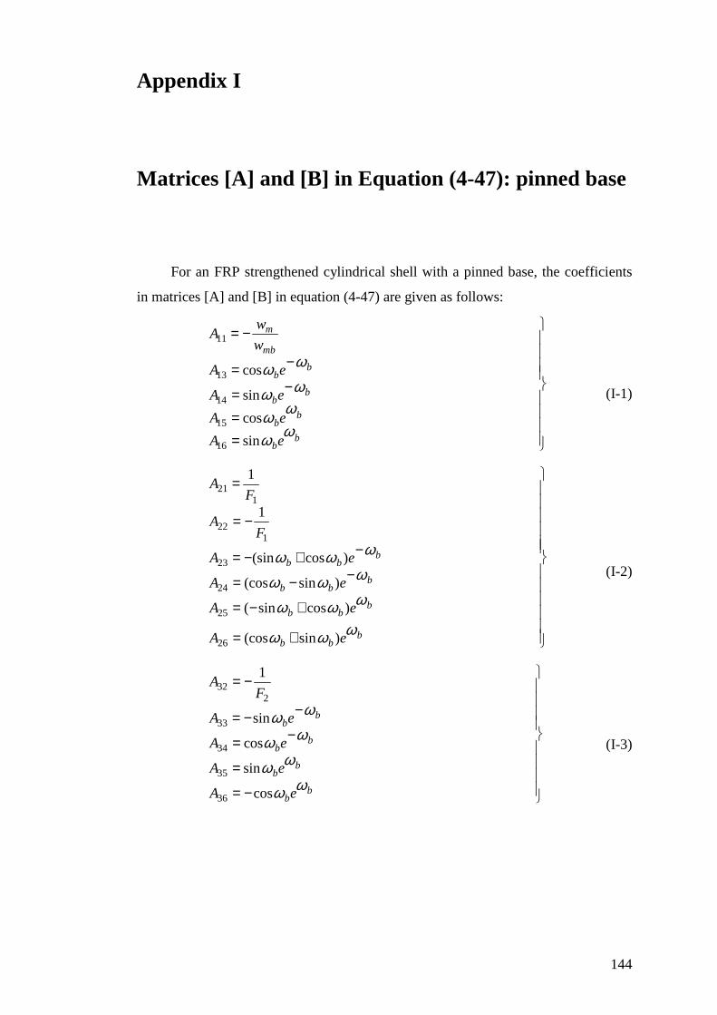
144
Appendix I
Matrices [A] and [B] in Equation (4-47): pinned base
For an FRP strengthened cylindrical shell with a pinned base, the coefficients
in matrices [A] and [B] in equation (4-47) are given as follows:
==
−=
−=
−=
bb
bb
bb
bb
mb
m
eA
eA
eA
eA
w
wA
ϖϖ
ϖϖ
ϖϖ
ϖϖ
sin
cos
sin
cos
16
15
14
13
11
(I-1)
+=
+−=
−−=
−+−=
−=
=
bbb
bbb
bbb
bbb
eA
eA
eA
eA
FA
FA
ϖϖϖ
ϖϖϖ
ϖϖϖ
ϖϖϖ
)sin(cos
)cossin(
)sin(cos
)cos(sin
1
1
26
25
24
23
122
121
(I-2)
−=
=
−=
−−=
−=
bb
bb
bb
bb
eA
eA
eA
eA
FA
ϖϖ
ϖϖ
ϖϖ
ϖϖ
cos
sin
cos
sin
1
36
35
34
33
232
(I-3)
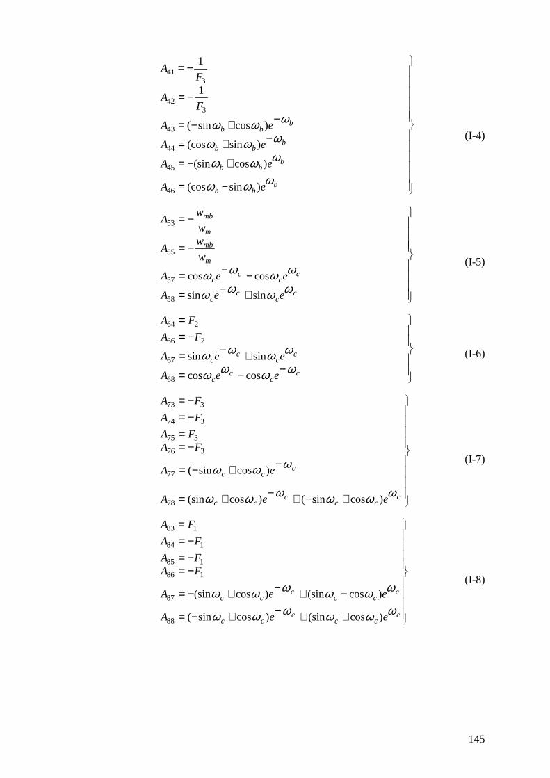
145
−=
+−=
−+=
−+−=
−=
−=
bbb
bbb
bbb
bbb
eA
eA
eA
eA
FA
FA
ϖϖϖ
ϖϖϖ
ϖϖϖ
ϖϖϖ
)sin(cos
)cos(sin
)sin(cos
)cossin(
1
1
46
45
44
43
342
341
(I-4)
+−=
−−=
−=
−=
cc
cc
cc
cc
m
mb
m
mb
eeA
eeA
w
wA
w
wA
ϖϖϖϖ
ϖϖϖϖ
sinsin
coscos
58
57
55
53
(I-5)
−−=
+−=
−==
cc
cc
cc
cc
eeA
eeA
FA
FA
ϖϖϖϖ
ϖϖϖϖ
coscos
sinsin
68
67
266
264
(I-6)
+−+−+=
−+−=
−==
−=−=
ccc
ccc
ccc
eeA
eA
FAFA
FA
FA
ϖϖϖϖϖϖ
ϖϖϖ
)cossin()cos(sin
)cossin(
78
77
376
375
374
373
(I-7)
++−+−=
−+−+−=
−=−=−=
=
ccc
ccc
ccc
ccc
eeA
eeA
FAFA
FA
FA
ϖϖϖϖϖϖ
ϖϖϖϖϖϖ
)cos(sin)cossin(
)cos(sin)cos(sin
88
87
186
185
184
183
(I-8)
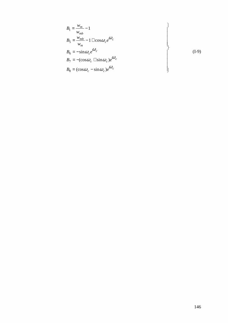
146
−=
+−=
−=
+−=
−=
ccc
ccc
cc
cc
m
mb
mb
m
eB
eB
eB
ew
wB
w
wB
ϖϖϖ
ϖϖϖ
ϖϖ
ϖϖ
)sin(cos
)sin(cos
sin
cos1
1
8
7
6
5
1
(I-9)

147
Appendix II
Matrices [A] and [B] in Equation (4-47): fixed base
For an FRP strengthened cylindrical shell with a fixed base, the coefficients in
matrices [A] and [B] in equation (4-47) are given as follows.
==
−=
−=
−=
bb
bb
bb
bb
mb
m
eA
eA
eA
eA
w
wA
ϖϖ
ϖϖ
ϖϖ
ϖϖ
sin
cos
sin
cos
16
15
14
13
11
(II-1)
+=
+−=
−−=
−+−=
−=
=
bbb
bbb
bbb
bbb
eA
eA
eA
eA
FA
FA
ϖϖϖ
ϖϖϖ
ϖϖϖ
ϖϖϖ
)sin(cos
)cossin(
)sin(cos
)cos(sin
1
1
26
25
24
23
122
121
(II-2)
−=
=
−=
−−=
−=
bb
bb
bb
bb
eA
eA
eA
eA
FA
ϖϖ
ϖϖ
ϖϖ
ϖϖ
cos
sin
cos
sin
1
36
35
34
33
232
(II-3)
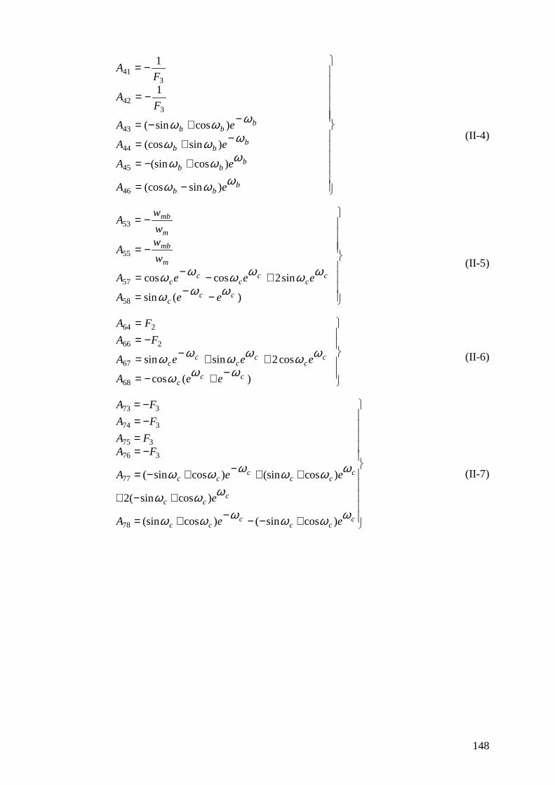
148
−=
+−=
−+=
−+−=
−=
−=
bbb
bbb
bbb
bbb
eA
eA
eA
eA
FA
FA
ϖϖϖ
ϖϖϖ
ϖϖϖ
ϖϖϖ
)sin(cos
)cos(sin
)sin(cos
)cossin(
1
1
46
45
44
43
342
341
(II-4)
−−=
+−−=
−=
−=
)(sin
sin2coscos
58
57
55
53
ccc
cc
cc
cc
m
mb
m
mb
eeA
eeeA
w
wA
w
wA
ϖϖϖ
ϖϖϖϖϖϖ (II-5)
−+−=
++−=
−==
)(cos
cos2sinsin
68
67
266
264
ccc
cc
cc
cc
eeA
eeeA
FA
FA
ϖϖϖ
ϖϖϖϖϖϖ (II-6)
+−−−+=
+−+
++−+−=
−==
−=−=
ccc
ccc
ccc
ccc
ccc
eeA
e
eeA
FAFA
FA
FA
ϖϖϖϖϖϖ
ϖϖϖ
ϖϖϖϖϖϖ
)cossin()cos(sin
)cossin(2
)cos(sin)cossin(
78
77
376
375
374
373
(II-7)
149
+−−+−=
++
−+−+−=
−=−=−=
=
ccc
ccc
c
cc
ccc
ccc
eeA
e
eeA
FAFA
FA
FA
ϖϖϖϖϖϖ
ϖϖϖ
ϖϖϖϖϖϖ
)cos(sin)cossin(
)cos(sin2
)cos(sin)cos(sin
88
87
186
185
184
183
(II-8)
−=
−=
+−=
−+−=
−=
cc
cc
ccc
ccc
m
mb
mb
m
eB
eB
eB
ew
wB
w
wB
ϖϖ
ϖϖ
ϖϖϖ
ϖϖϖ
sin2
cos2
)cos(sin6
)sin(cos1
1
8
7
5
1
(II-9)