stress and displacement patterns in the craniofacial
TRANSCRIPT

RESEARCH Open Access
Stress and displacement patterns in thecraniofacial skeleton with rapid maxillaryexpansion—a finite element method studyJ. Priyadarshini1, C. M. Mahesh2, B. S. Chandrashekar2, Abhishek Sundara2* , A. V. Arun2 and Vinay P. Reddy2
Abstract
Background: Rapid maxillary expansion (RME), indicated in the treatment of maxillary deficiency directs high forcesto maxillary basal bone and to other adjacent skeletal bones. The aim of this study is to (i) evaluate stress distributionalong craniofacial sutures and (ii) study the displacement of various craniofacial structures with rapid maxillaryexpansion therapy by using a Finite Element model.
Methods: An analytical model was developed from a dried human skull of a 12 year old male. CT scan images of theskull were taken in axial direction parallel to the F-H plane at 1 mm interval, processed using Mimics software, requiredportion of the skull was exported into stereo-lithography model. ANSYS software was used to solve the mathematicalequation. Contour plots of the displacement and stresses were obtained from the results of the analysis performed.
Results: At Node 47005, maximum X-displacement was 5.073 mm corresponding to the incisal edge of the uppercentral incisor. At Node 3971, maximum negative Y-displacement was -0.86 mm which corresponds to the anteriorzygomatic arch, indicating posterior movement of craniofacial complex. At Node 32324, maximum negativeZ-displacement was -0.92 mm representing the anterior and deepest convex portion of the nasal septum; indicatingdownward displacement of structures medial to the area of force application.
Conclusions: Pyramidal displacement of maxilla was evident. Apex of pyramid faced the nasal bone and base waslocated on the oral side. Posterosuperior part of nasal cavity moved minimally in lateral direction and width of nasalcavity at the floor of the nose increased, there was downward and forward movement of maxilla with a tendencytoward posterior rotation. Maximum von Mises stresses were found along midpalatal, pterygomaxillary, nasomaxillaryand frontomaxillary sutures.
Keywords: Finite element analysis, Rapid Maxillary Expansion, Craniofacial sutures, Displacement
BackgroundOrthodontics and dentofacial orthopedics have changedfrom an opinion-based practice to evidence-based prac-tice. Rapid maxillary expansion (RME) is indicated inthe treatment of maxillary deficiency. During RME, highforces directed to the maxillary basal bone and perhapsto other adjacent skeletal bones can easily split themid-palatal suture in young individuals and force thetwo maxillary halves laterally. Midfacial orthopedic ex-pansion has been recommended for use in conjunction
with protraction forces on the maxilla because it disruptsthe circum-maxillary sutural system and presumably facil-itates the orthopedic effect of the facemask [1, 2]. Variouscraniofacial areas especially in the areas of articulation ofthe maxilla are also effected [3]. A recent study usedcone-beam computed tomography imaging to concludethat RME resulted in forward movement of the maxilla aswell and also vertical dentoalveolar changes [4].It is still an enigma as to where these areas of maximum
force concentration are and how these heavy forces getdissipated. Sutures undergo anabolic changes such asincreased sutural width, angiogenesis, and bone appositionin response to anteriorly directed forces. Studies providedhistologic descriptions of sutural response to both tensile
* Correspondence: [email protected] of Orthodontics and Dentofacial Orthopaedics, KrishnadevarayaCollege of Dental Sciences, Hunasamaranahalli, New Airport Road, Bangalore562157, Karnataka, IndiaFull list of author information is available at the end of the article
© The Author(s). 2017 Open Access This article is distributed under the terms of the Creative Commons Attribution 4.0International License (http://creativecommons.org/licenses/by/4.0/), which permits unrestricted use, distribution, andreproduction in any medium, provided you give appropriate credit to the original author(s) and the source, provide a link tothe Creative Commons license, and indicate if changes were made.
Priyadarshini et al. Progress in Orthodontics (2017) 18:17 DOI 10.1186/s40510-017-0172-2

and compressive forces. Bone formation has been observedat the edges of the mid-palatal suture after rapid palatalexpansion [5].In recent years, finite element method (FEM) has been
a powerful research tool for solving various structuralmechanical problems. It is recognized as a general pro-cedure for mechanical approximation to all physicalproblems that can be modeled by differential equationdescription [6].Previous study assessed the stress and displacement in
the maxilla alone [7]. The present study encompasses
Fig. 1 Dried young human skull of a 12-year-old male
Fig. 2 Frontal view of the three-dimensional FE model
Fig. 3 Lateral view of the three-dimensional FE model
Fig. 4 Basal view of the three-dimensional FE model
Priyadarshini et al. Progress in Orthodontics (2017) 18:17 Page 2 of 8
the changes produced in the entire craniofacial complexand was planned to explore how heavy transverse ortho-pedic forces generated by RME get dissipated within thecraniofacial complex and to evaluate the pattern of stressaccumulation, dissipation, and displacement of variousvcraniofacial structures with RME appliance using athree-dimensional FEM study by using a model that betterrepresents the human skull than previously presented.
Aims and objectivesThe aims of this study are as follows:
1. To evaluate stress distribution along craniofacialsutures
2. To study the displacement of various craniofacialstructures with RME therapy by using a finiteelement model
MethodsComputed tomography (CT) scan images of a 12-year-old boy’s cranium were taken by Spiral CT Scan Ma-chine (X-Force/SH spiral CT scan machine manufac-tured by Toshiba) (Fig. 1). The entire skull excluding themandible were sliced at 1-mm interval, and nodes areassigned to the bones and sutures of interest. A 3D
CAD model was created using Mimics software. Mimicssoftware helps to import and visualize and helps in 3Drendering, 3D information, reslicing, and measuring theCT scan details.A 3D CAD model was imported into Hypermesh Soft-
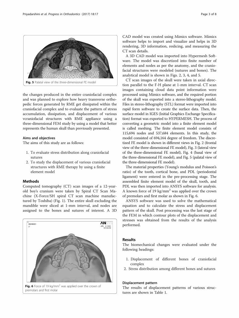
ware. The model was discretized into finite number ofelements and nodes as per the anatomy, and the cranio-facial structures were modeled (sutures and bones). Theanalytical model is shown in Figs. 2, 3, 4, and 5.CT scan images of the skull were taken in axial direc-
tion parallel to the F-H plane at 1-mm interval. CT scanimages containing cloud data point information wereprocessed using Mimics software, and the required portionof the skull was exported into a stereo-lithography model.Files in stereo-lithography (STL) format were imported intorapid form software to create the surface data. Then, thesurface model in IGES (Initial Graphics Exchange Specifica-tion) format was exported to HYPERMESH. The process ofconverting a geometric model into a finite element modelis called meshing. The finite element model consists of115,694 nodes and 537,684 elements. In this study, themodel consisted of 694,164 degree of freedom. The discre-tized FE model is shown in different views in Fig. 2 (frontalview of the three-dimensional FE model), Fig. 3 (lateral viewof the three-dimensional FE model), Fig. 4 (basal view ofthe three-dimensional FE model), and Fig. 5 (palatal view ofthe three-dimensional FE model).The material properties (Young’s modulus and Poisson’s
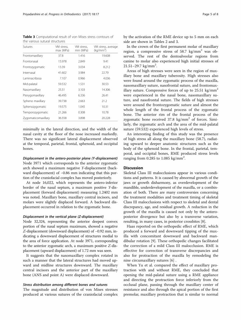
ratio) of the tooth, cortical bone, and PDL (periodontalligament) were entered in the pre-processing stage. Theassembled finite element model of the skull, tooth, andPDL was then imported into ANSYS software for analysis.A known force of 19 kg/mm2 was applied over the crownof premolars and first molar as shown in Fig. 6.ANSYS software was used to solve the mathematical
equation and to calculate the stress and displacementpattern of the skull. Post processing was the last stage ofthe FEM in which contour plots of the displacement andstresses was obtained from the results of the analysisperformed.
ResultsThe biomechanical changes were evaluated under thefollowing headings:
1. Displacement of different bones of craniofacialcomplex
2. Stress distribution among different bones and sutures
Displacement patternThe results of displacement patterns of various struc-tures are shown in Table 1.
Fig. 6 Force of 19 kg/mm2 was applied over the crown ofpremolars and first molar
Fig. 5 Palatal view of the three-dimensional FE model
Priyadarshini et al. Progress in Orthodontics (2017) 18:17 Page 3 of 8

Displacement in the transverse plane (X-displacement)Node 47,005 mm corresponding to the incisal edge of theupper central incisor showed maximum X-displacement(lateral displacement), and it was measured to be 5.073 mm.From the frontal view, the pyramidal displacement of themaxilla was evident. The apex of the pyramid faced thenasal bone, and the base was located on the oral side.Viewed occlusally, the two halves of the maxillary den-
toalveolar complex, basal maxilla, and lateral walls of thenasal cavity separated more widely, anteriorly. The pos-terosuperior part of the nasal cavity had moved
Table 1 Computational result of the transversal (X), sagittal (Y), and vertical (Z) displacements of the various skeletal structures of thecraniofacial complex following 5 mm of transverse expansion on application of 19 kg/mm2 force
Region Selected node X (mm) Y (mm) Z (mm)
Dentoalveolar Incisal edge of 1 (47,005) 5.073 0.79 0.42
Cusp tip 3 (44,665) 5.068 0.65 0.28
Cusp tip 6 (35,146) 5.068 0.69 0.28
Apical region of 1 (106,126) 4.281 0.93 −0.62
Apical region of 3 (99,505) 3.878 0.43 0.28
Apical region of 6 (112,557) 4.273 0.37 0.32
Palate Anterior part of palate (17,631) 3.077 1.21 −0.81
Posterior part (17,161) 2.09 1.12 −0.98
Maxilla Point “A” (32,324) 3.55 0.86 −0.92
ANS (16,022) 3.078 1.24 −0.72
Tuberosity (12,721) 3.26 0.55 0.32
Zygomatic buttress (11,611) 2.89 0.019 0.85
Inferior orbital rim (10,586) 1.97 −0.21 0.90
Frontal process (14,235) 1.00 0.078 −0.22
Nasal cavity wall Antero-inferior (17,902) 2.95 0.43 0.02
Anterosuperior (14,894) 1.41 0.21 −0.02
Posteroinferior (14,131) 1.93 0.42 −0.35
Posterosuperior (17,005) 0.49 0.009 −0.04
Nasal bone Body (16,523) 0.31 −0.63 −0.71
Sphenoid bone Lateral pterygoid inferior (24,419) 1.91 0.63 −0.52
Lateral pterygoid superior (24,118) 0.651 0.06 0.18
Medial pterygoid inferior (20,674) 1.88 −0.53 −0.39
Medial pterygoid superior (24,011) 0.146 −0.09 0.23
Greater wing (29,115) 0.33 −0.41 0.67
Zygomatic bone Body (5320) 0.25 −0.83 1.64
Frontal process (22,309) 2.19 −1.2 1.62
Zygomatic arch anterior (3971) 0.55 −0.86 1.72
Zygomatic arch posterior (3907) 0.045 −0.42 0.08
Frontal bone Supraorbital (7846) 0.015 −0.02 0.12
Forehead (18,937) 0.02 −0.03 0.065
Temporal bone Squamous (3786) 0.55 −0.28 0.36
Parietal Tuberosity (31,299) 0.09 −0.27 0.41
Occipital Squamous (20,670) 0.014 −0.09 0.03
Table 2 Computational result of von Mises stress contours ofthe various skeletal structures
Bones VM stress, max(kg/mm2)
VM stress, min(kg/mm2)
VM stress, average(kg/mm2)
Frontal bone 42.74 0.285 21.51
Maxillary bone 58.7 0.747 29.7
Nasal bone 51.7 3.628 27.66
Sphenoid bone 20.96 0.25 10.605
Temporal bone 26.905 0.15 13.52
Zygomatic bone 44.602 0.573 22.58
Priyadarshini et al. Progress in Orthodontics (2017) 18:17 Page 4 of 8
minimally in the lateral direction, and the width of thenasal cavity at the floor of the nose increased markedly.There was no significant lateral displacement observedat the temporal, parietal, frontal, sphenoid, and occipitalbones.
Displacement in the antero-posterior plane (Y-displacement)Node 3971 which corresponds to the anterior zygomaticarch showed a maximum negative Y-displacement (back-ward displacement) of −0.86 mm indicating that this por-tion of the craniofacial complex has moved posteriorly.At node 16,022, which represents the antero-inferior
border of the nasal septum, a maximum positive Y-dis-placement (forward displacement) measuring 1.2402 mmwas noted. Maxillary bone, maxillary central incisors, andmolars were slightly displaced forward. A backward dis-placement occurred in relation to the zygomatic bone.
Displacement in the vertical plane (Z-displacement)Node 32,324, representing the anterior deepest convexportion of the nasal septum maximum, showed a negativeZ-displacement (downward displacement) of −0.92 mm, in-dicating a downward displacement of structures medial tothe area of force application. At node 3971, correspondingto the anterior zygomatic arch, a maximum positive Z-dis-placement (upward displacement) of 1.72 mm was seen.It suggests that the nasomaxillary complex rotated in
such a manner that the lateral structures had moved up-ward and midline structures downward. The maxillarycentral incisors and the anterior part of the maxillarybone (ANS and point A) were displaced downward.
Stress distribution among different bones and suturesThe magnitude and distribution of von Mises stressesproduced at various sutures of the craniofacial complex
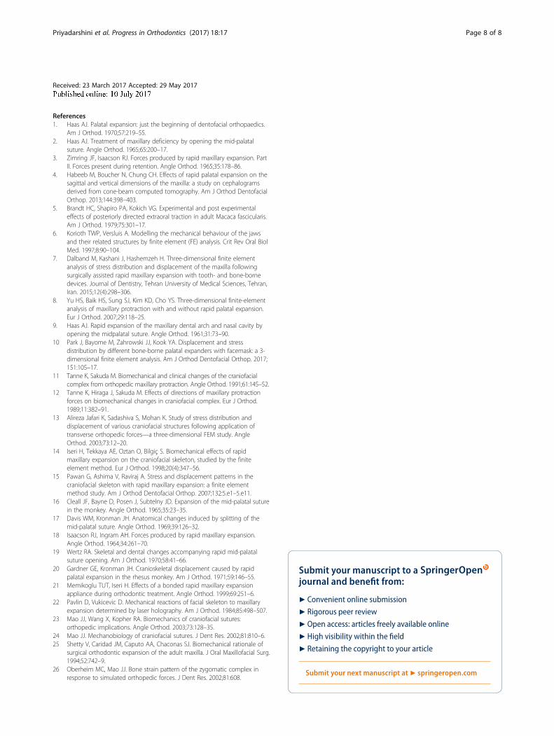
by the activation of the RME device up to 5 mm on eachside are shown in Tables 2 and 3.In the crown of the first permanent molar of maxillary
region, a compressive stress of 58.7 kg/mm2 was ob-served. The rest of the dentoalveolar regions fromcanine to molar also experienced high initial stresses of21.51–29.7 kg/mm2.Areas of high stresses were seen in the region of max-
illary bone and maxillary tuberosity. High stresses alsowere found around the zygomatic process of the maxilla,nasomaxillary suture, nasofrontal suture, and frontomax-illary suture. Compressive forces of up to 25.51 kg/mm2
were experienced in the nasal bone, nasomaxillary su-ture, and nasofrontal suture. The fields of high stresseswere around the frontozygomatic suture and almost thewhole length of the frontal process of the zygomaticbone. The anterior rim of the frontal process of thezygomatic bone received 37.8 kg/mm2 of forces. Simi-larly, the zygomatic arch and the area of the mid-palatalsuture (59.532) experienced high levels of stress.An interesting finding of this study was the presence
of high stress all along the maxillary bone (58.7), radiat-ing upward to deeper anatomic structures such as thebody of the sphenoid bone. In the frontal, parietal, tem-poral, and occipital bones, RME produced stress levelsranging from 0.285 to 1.085 kg/mm2.
DiscussionSkeletal Class III malocclusions appear in various condi-tions and patterns. It is caused by abnormal growth of thejaws or growth disharmony, as overdevelopment of themandible, underdevelopment of the maxilla, or a combin-ation of both. There are many controversies concerningthe treatment modalities and treatment timing of skeletalClass III malocclusions with respect to skeletal and dentaldiscrepancy, age, and residual growth. A reduction in thegrowth of the maxilla is caused not only by the antero-posterior divergence but also by a transverse variation,resulting, in many cases, in posterior crossbites [8].Haas reported on the orthopedic effect of RME, which
produced a forward and downward tipping of the max-illa with concomitant downward and backward man-dibular rotation [9]. These orthopedic changes facilitatedthe correction of a mild Class III malocclusion. RME iseffective for correction of transverse discrepancies andalso for protraction of the maxilla by remodeling thenine circumaxillary sutures [6] .When Yu et al. compared the effect of maxillary pro-
traction with and without RME, they concluded thatopening the mid-palatal suture using a RME applianceand directing the protraction force inferiorly from theocclusal plane, passing through the maxillary center ofresistance and also through the apical portion of the firstpremolar, maxillary protraction that is similar to normal
Table 3 Computational result of von Mises stress contours ofthe various sutural structures
Sutures VM stress,max (MPa)
VM stress,min (MPa)
VM stress, average(kg/mm2)
Frontomaxillary 37.8 1.416 19.608
Frontonasal 15.978 2.849 9.41
Frontozygomatic 13.39 3.034 8.212
Internasal 41.602 3.984 22.79
Laminacribosa 7.107 0.966 4.036
Mid-palatal 59.532 1.531 30.53
Nasomaxillary 25.51 3.103 14.306
Pterygomaxillary 46.495 6.336 26.41
Spheno maxillary 39.738 2.663 21.2
Sphenozygomatic 19.575 1.045 10.31
Temporozygomatic 21.266 0.308 10.78
Zygomaticomaxillary 36.558 3.898 20.228
Priyadarshini et al. Progress in Orthodontics (2017) 18:17 Page 5 of 8

downward and forward growth of the maxilla can beeffectively achieved [8].In yet another study by Park et al. to analyze displace-
ment and stress distribution in the maxilla during maxillaryexpansion followed by protraction using bone-borne andconventional tooth-borne palatal expanders and a facemaskvia three-dimensional finite element analysis, they con-cluded that the group with only facemask resulted in moreanterior displacement of the maxilla than the combinationof facemask and bone-borne expanders. Further, tooth-borne expanders reported more anterior movement of themaxilla when protraction was combined with expansionand compared with protraction without expansion. This isdue to the synergistic effect when combined with the face-mask as reported by Yu et al. [8].The three-dimensional FEM used in the present study
provides the freedom to simulate orthodontic forcesystems applied clinically and allows analysis of theresponse of the craniofacial skeleton to the orthodonticloads in three-dimensional space. The FEM has severaladvantages, and the study can be repeated as many timesas the operator wishes [10].Sequential CT scan images were taken at 1-mm intervals
to reproduce finer and detailed aspects of the geometry.Previous studies reported sections at 10-mm [11, 12],5-mm [13, 14], and 2.5-mm [15] intervals. This studydiffers from previous studies in the type of elementused for meshing and solid tetrahedral elements used,each having 10 nodes, giving better stress transmissibilityand bending deformations. Therefore, this model is abetter representation of a real human skull than theprevious models [13, 14].
Displacement of various craniofacial structures with rapidmaxillary expansion by using finite element analysisMaximum lateral displacement was at the incisal edge ofthe upper central incisor. The pyramidal displacement ofmaxilla was evident. The apex of the pyramid faced thenasal bone, and the base was located on the oral side.The posterosuperior part of the nasal cavity had movedminimally in the lateral direction, and the width of thenasal cavity at the floor of the nose increased markedly,whereas no significant lateral displacement was observedat the temporal, parietal, frontal, sphenoid, and occipitalbones. The studies done by Haas et al., Jafari et al. [13],Cleall et al. [16], Davis and Kronman [17], and Iseri etal. [14] showed similar findings.The maximum negative Y-displacement (backward
displacement) was observed at the anterior zygomaticarch, indicating that this portion of the craniofacialcomplex had moved posteriorly. In a similar study doneby Jafari et al. [13], the maximum negative Y-displacementwas less compared to our study. The difference may bedue to (i) CT scan images were taken at 5-mm interval,
(ii) analysis of the complete skull was not considered as itwas thought that the analysis of one half of the craniumwill mirror similar results on the opposite side, and (iii) aknown force was not applied.The present study suggests that the resistance of the
mid-palatal opening is probably not in the suture itselfbut in the surrounding structures of the sphenoid andzygomatic bones, thus confirming the studies done inthe past by Isaacson and Ingram [18] and Wertz [19].When the mid-palatal suture opens with RME therapy,
the maxilla always moves downward and forward. This isprobably due to the disposition of the maxilla-cranial su-tures [1]. This was demonstrated by anterior and down-ward displacement of point A, ANS, and prosthion. Thisis in accordance with previous studies [13, 14, 19, 20].The pterygoid plates can bend only to a limited extent
with pressure, and this confining effect of the pterygoidplates of the sphenoid minimizes the ability of the palat-ine bones to separate at the midsagittal plane [18].An increase in nasal width has been demonstrated as a
response to RME [1, 2, 19, 21]. The numerical resultsdemonstrate that the width of the nasal cavity at thefloor of the nose increased markedly compared to thesuperior part. This result is similar to Pavlin and Vukicevik’sstudy [22]. Therefore, a combination of increase in nasalwidth, lowering of palatal plane, and probably straighteningof the nasal septum after RME can help the patients withnasal stenosis, by increasing air flow.This study also provided additional explanation about the
bony tissue mechanical reactions, which are the first steps inthe compound process of tissue response to jaw expansion.
Evaluation of stress distribution along craniofacial suturesThe von Mises stresses were used for this analysisbecause of the appropriateness and the validity of thevon Mises theory of failure [14].The present study showed that the mid-palatal suture
had experienced high levels of stress (59.532 MPa). Aninteresting finding of this study was the presence of highstress all along the maxillary bone (58.7 MPa), radiatingupward to deeper anatomic structures such as the bodyof the sphenoid bone.Mechanical stresses elicited by exogenous forces are ex-
perienced and transmitted by sutures [23]. Sutural strainpatterns are similar between dry skull models and thesame structures in vivo [23]. Sutures have a range of mo-bility and certainly are not immovable joints when theyare patent. Mechanical stresses experienced in sutures,with the right characteristics, can modulate sutural growth[24]. This had been proved time and again. Our presentstudy also confirmed this.The present study concludes that mid-palatal suture
shows a maximum von Mises stress followed by pterygo-maxillary, nasomaxillary, and frontomaxillary sutures in
Priyadarshini et al. Progress in Orthodontics (2017) 18:17 Page 6 of 8

the descending order of frequency. This is contrary tostudies done by Jafari et al. [13]. The difference observedmay be attributed to the sample used for the generationof FE model and selection of nodes and elements. In thepresent study, a known force is applied instead of knowndisplacement.The study done by Shetty et al. [25] showed that in the
anterior region, the forces spread superomedially alongthe frontal process of the maxilla and the medial orbitalwall up to the junction of the nasal and lacrimal bones.The primary stresses in their study radiated laterally to thezygomaticomaxillary and the zygomaticofrontal sutures,which is contrary to our findings. This difference may beattributed to discretization process during FE model gen-eration and selection of nodes and elements.In this study, the lateral stresses mainly radiated to the
zygomaticotemporal and the sphenozygomatic suturesand it has been demonstrated that the pattern of stressdistribution was different along the various craniofacialsutures in response to RME. Both tensile and compressivestresses of variable magnitude were demonstrated alongthe same suture. The zygomaticomaxillary, zygomatico-temporal, and zygomaticofrontal sutures were associatedwith both tensile and compressive stresses. Sutural growthis accelerated by both tension and compression withappropriate parameters such as strain amplitude, rate, anddose [23].The presence of differential strain patterns suggests the
possibility of differential bone remodeling along the samesuture. Differential strain patterns and magnitudes alongthe same suture were documented by Oberheim and Mao[26] who showed contrasting bone-strain patterns in zygo-matic arch across zygomaticotemporal suture—i.e., tensileon its lateral surface and compressive on its medial surfa-ce—suggesting potentially differential growth responses ofzygomatic arch with headgear therapy.The absolute level of induced stresses greatly depends
on bone elasticity and patient’s age. With the same ortho-pedic load, equivalent sutures of juvenile skulls experiencesignificantly higher bone strain than adult skulls, suggest-ing that same mechanical force might have different bio-logic effects on immature and mature facial skeletons.It may be noted that any variation in values between
this study and other studies may be attributed to thesample used for the generation of FEM or the modelgenerated on the computer (or both) or selection of thenodes and elements on the FEM (or both).
ConclusionsThe conclusions are as follows:
1. Pyramidal displacement of the maxilla was evident.The apex of the pyramid faced the nasal bone, andthe base was located on the oral side.
2. Posterosuperior part of the nasal cavity movedminimally in the lateral direction, and width of thenasal cavity at the floor of the nose increased markedly.
3. There were downward and forward movements of themaxilla with a tendency toward posterior rotation.
4. Pterygoid plates were displaced laterally.5. In the frontal plane, the center of rotation of the maxilla
was approximately near the superior orbital fissure.6. Maximum von Mises stresses were found along
mid-palatal, pterygomaxillary, nasomaxillary, andfrontomaxillary sutures in a descending order offrequency.
7. Zygomaticomaxillary, zygomaticotemporal, andzygomaticofrontal sutures were associated with bothtensile and compressive stresses.
8. Bilateral pterygomaxillary and zygomatic buttressosteotomies are essential when carrying outsurgically assisted RME in adults.
9. The mid-palatal suture had experienced highlevels of stress; an interesting finding of thisstudy was the presence of high stress all alongthe maxillary bone, radiating upward to deeperanatomic structures such as the body of thesphenoid bone.
AbbreviationsCAD: Computer-assisted design; CT: Computed tomography; FE: Finiteelement; FEM: Finite element method; IGES: Initial Graphic ExchangeSpecification; PDL: Periodontal ligament; RME: Rapid maxillary expansion;STL: Stereo-lithography
AcknowledgementsI thank Dr. Bobby Joseph, Dr. Aditi Nedungadi, and Dr. Amit K Ohja fortheir constant support and guidance given to us in preparing thismanuscript.
FundingNot applicable.
Authors’ contributionsPJ made substantial contributions to the conception, design, and acquisitionof the data. AS contributed to the drafting of the manuscript. MCM and CBShave been involved in correcting the manuscript and revising it critically forimportant intellectual content. AAV and VPR gave final approval of theversion to be published. All authors read and approved the final manuscript.
Competing interests.The authors declare that they have no competing interests.
Consent for publicationNot applicable.
Ethics approval and consent to participateNot applicable,
Publisher’s NoteSpringer Nature remains neutral with regard to jurisdictional claims inpublished maps and institutional affiliations.
Author details1Private Practice, Bellary, Karnataka, India. 2Department of Orthodontics andDentofacial Orthopaedics, Krishnadevaraya College of Dental Sciences,Hunasamaranahalli, New Airport Road, Bangalore 562157, Karnataka, India.
Priyadarshini et al. Progress in Orthodontics (2017) 18:17 Page 7 of 8
Received: 23 March 2017 Accepted: 29 May 2017
References1. Haas AJ. Palatal expansion: just the beginning of dentofacial orthopaedics.
Am J Orthod. 1970;57:219–55.2. Haas AJ. Treatment of maxillary deficiency by opening the mid-palatal
suture. Angle Orthod. 1965;65:200–17.3. Zimring JF, Isaacson RJ. Forces produced by rapid maxillary expansion. Part
II. Forces present during retention. Angle Orthod. 1965;35:178–86.4. Habeeb M, Boucher N, Chung CH. Effects of rapid palatal expansion on the
sagittal and vertical dimensions of the maxilla: a study on cephalogramsderived from cone-beam computed tomography. Am J Orthod DentofacialOrthop. 2013;144:398–403.
5. Brandt HC, Shapiro PA, Kokich VG. Experimental and post experimentaleffects of posteriorly directed extraoral traction in adult Macaca fascicularis.Am J Orthod. 1979;75:301–17.
6. Korioth TWP, Versluis A. Modelling the mechanical behaviour of the jawsand their related structures by finite element (FE) analysis. Crit Rev Oral BiolMed. 1997;8:90–104.
7. Dalband M, Kashani J, Hashemzeh H. Three-dimensional finite elementanalysis of stress distribution and displacement of the maxilla followingsurgically assisted rapid maxillary expansion with tooth- and bone-bornedevices. Journal of Dentistry, Tehran University of Medical Sciences, Tehran,Iran. 2015;12(4):298–306.
8. Yu HS, Baik HS, Sung SJ, Kim KD, Cho YS. Three-dimensional finite-elementanalysis of maxillary protraction with and without rapid palatal expansion.Eur J Orthod. 2007;29:118–25.
9. Haas AJ. Rapid expansion of the maxillary dental arch and nasal cavity byopening the midpalatal suture. Angle Orthod. 1961;31:73–90.
10 Park J, Bayome M, Zahrowski JJ, Kook YA. Displacement and stressdistribution by different bone-borne palatal expanders with facemask: a 3-dimensional finite element analysis. Am J Orthod Dentofacial Orthop. 2017;151:105–17.
11 Tanne K, Sakuda M. Biomechanical and clinical changes of the craniofacialcomplex from orthopedic maxillary protraction. Angle Orthod. 1991;61:145–52.
12 Tanne K, Hiraga J, Sakuda M. Effects of directions of maxillary protractionforces on biomechanical changes in craniofacial complex. Eur J Orthod.1989;11:382–91.
13 Alireza Jafari K, Sadashiva S, Mohan K. Study of stress distribution anddisplacement of various craniofacial structures following application oftransverse orthopedic forces—a three-dimensional FEM study. AngleOrthod. 2003;73:12–20.
14 Iseri H, Tekkaya AE, Oztan O, Bilgiç S. Biomechanical effects of rapidmaxillary expansion on the craniofacial skeleton, studied by the finiteelement method. Eur J Orthod. 1998;20(4):347–56.
15 Pawan G, Ashima V, Raviraj A. Stress and displacement patterns in thecraniofacial skeleton with rapid maxillary expansion: a finite elementmethod study. Am J Orthod Dentofacial Orthop. 2007;132:5.e1–5.e11.
16 Cleall JF, Bayne D, Posen J, Subtelny JD. Expansion of the mid-palatal suturein the monkey. Angle Orthod. 1965;35:23–35.
17 Davis WM, Kronman JH. Anatomical changes induced by splitting of themid-palatal suture. Angle Orthod. 1969;39:126–32.
18 Isaacson RJ, Ingram AH. Forces produced by rapid maxillary expansion.Angle Orthod. 1964;34:261–70.
19 Wertz RA. Skeletal and dental changes accompanying rapid mid-palatalsuture opening. Am J Orthod. 1970;58:41–66.
20 Gardner GE, Kronman JH. Cranioskeletal displacement caused by rapidpalatal expansion in the rhesus monkey. Am J Orthod. 1971;59:146–55.
21 Memikoglu TUT, Iseri H. Effects of a bonded rapid maxillary expansionappliance during orthodontic treatment. Angle Orthod. 1999;69:251–6.
22 Pavlin D, Vukicevic D. Mechanical reactions of facial skeleton to maxillaryexpansion determined by laser holography. Am J Orthod. 1984;85:498–507.
23 Mao JJ, Wang X, Kopher RA. Biomechanics of craniofacial sutures:orthopedic implications. Angle Orthod. 2003;73:128–35.
24 Mao JJ. Mechanobiology of craniofacial sutures. J Dent Res. 2002;81:810–6.25 Shetty V, Caridad JM, Caputo AA, Chaconas SJ. Biomechanical rationale of
surgical orthodontic expansion of the adult maxilla. J Oral Maxillofacial Surg.1994;52:742–9.
26 Oberheim MC, Mao JJ. Bone strain pattern of the zygomatic complex inresponse to simulated orthopedic forces. J Dent Res. 2002;81:608.
Priyadarshini et al. Progress in Orthodontics (2017) 18:17 Page 8 of 8