string transportation system - yunitskiy.com · high-speed string transportation route ......
TRANSCRIPT

UNITSKY STRING TRANSPORT Co. Ltd
e-mail: [email protected] http: //www.unitsky.ru http: //www.stt21.ru
Pre-project Proposal
High-speed String Transportation Route “ABU DHABI — DUBAI — SHARJAH”
Moscow 2005

Contents
1. Introduction ........................................................................................................ 3
1.1. String ..................................................................................................... 3
1.2. String-rail............................................................................................... 3
1.3. Track structure ....................................................................................... 4
1.4. Supports ................................................................................................. 4
1.5. Wheel ..................................................................................................... 4
1.6. Transportation module .......................................................................... 5
1.7. Infrastructure ......................................................................................... 5
1.8. Project solutions .................................................................................... 7
1.9. UST operation ....................................................................................... 7
1.10. Approbation ......................................................................................... 7 2. Layout scheme of UST route ............................................................................. 8
3. Technical and economic characteristics of a double-track
high-speed UST route ―Abu Dhabi — Sharjah‖ ................................................ 11
3.1. Expected passenger flow ....................................................................... 12
3.2. Expected freight flow ............................................................................ 12
3.3. Organization of traffic ........................................................................... 12
3.4. Transportation module requirements .................................................... 13
3.5. Travel time and circulation along the route .......................................... 13
3.6. Annual income and operation profitability of the route ........................ 14
3.7. Comparative technical and economic indices of the route
depending on the size of freight and passenger flows .......................... 15

3
1. Description of Unitsky String Transport
Unitsky String Transport (UST) is designed as a string rail road elevated on the
supports above the ground along which wheeled transportation modules (unibuses)
with 50-passenger and up to 5 tons of freight capacity are circulating with the
travel speed up to 350 km/hour.
UST is the cheapest, most durable, economically efficient and safe system among
all other known modes of transportation of the second level, i.e. systems with the
elevated track structure installed on the supports such as train on a magnet
suspension, mono-rail and cable roads. The UST advantages against other modes
of transportation could be attributed to the following complex of its structural
peculiarities.
1.1. String
String is made of twisted seven-wire K-7 cable with 15.2 mm diameter. Depending
on assembly and operation conditions traditional cables (breaking stress — 24—26
tons, permissible normative strength in the track structure — 14 tons), cables with
a protective cover or polyethylene envelope including protective lubrication
(breaking stress — 26—28 tons, permissible strength — 20 tons) are used. The
cost of cable is USD 1,000-3,000 per 1 ton.
1.2. String-rail
String-rail is an ordinary continuous
(along the whole length) steel,
reinforced concrete or steel-reinforced
concrete beam equipped with a rail
head and additionally reinforced with
pre-stressed (stretched) strings (Fig. 1).
Maximal string stress per one rail
(depending on a span length and mass
of the rolling stock) is 200—500 tons
(at +20°C temperature). It combines the
qualities of a flexible thread (at a large
span between the supports) and a rigid
beam (at a small span under the wheel
of a transportation module and above
the support) and when exposed to the
concentrated load of a wheel the
deflection (curvature) radius of a string-rail will be equal to 300—500 m and more.
Therefore, it enables a wheel to roll smoothly, without shocks both in the middle of
Fig. 1. Design alternative
of a string-rail and wheel

4
a span and above the support. A string-rail is characterized by a high degree of
strength, rigidity, smoothness, technological production and mounting, low
material consumption (steel: 20—60 km/m, concrete: 0.005—0.02 cub. m/m), a
wide range of working temperatures (from +70 to –70°C).
It provides an ideally smooth road for the rolling wheels as it has no technological
or temperature joints along its whole length (rail head is welded as a single
weaving). The cost of the assembled string-rail is USD 100,000 per 1 km which,
for example, is less than the cost of assembled railway rail of a trunk line.
1.3. Track structure
Track structure is designed as two string-rails to make a gauge of 2,000 mm width.
It is equipped with switch-over devices similar to those used for trams. It is
possible to install it on the supports, on the ground (with a special sleeper frame,
spacing between sleepers — 5—10 m), or on a sand, gravel or concrete
longitudinal (0.2—0.4 m wide) cushion. It could be designed as dismountable
structure. A UST gauge is almost 1.4 times wider than that of a railway and centre
of mass of the rolling stock is located 1.5-2 times lower to ensure steadiness of
movement along such track to be 2—3 times higher.
1.4. Supports
Supports are subdivided into anchor supports, exposed to horizontal load of strings
(installed every 2—3 km) and supporting masts exposed to vertical load (installed
every 10—50 m and more). For UST routes it is possible to use either earlier
designed standard supports with their height ranging from 0.5 to 20 m, made of
reinforced concrete (assembled or monolithic) or steel welded structures and
additionally designed supports meeting special customer requirements. Depending
on soil peculiarities either pile (driving, screw, filling, injected) or slab (monolithic
or assembled) foundations are possible. Supports could be installed practically in
any kind of soils. Supports and unsplit string-rail form a rigid frame structure
therefore bearing capacity of supports is increased, for example, compared with a
mono-rail by 8 times (the cost of supports was accordingly reduced). The cost of
intermediate and anchor support is USD 500 and USD 50,000, respectively. If
UST supports were replaced by an embankment of the same height its cost would
be higher.
1.5. Wheel
Wheel is made of high-strength steel (Fig. 1). It has an independent ―automobile‖
suspension and two rims each 40 mm high (against a wheel pair and one rim 30
mm high in each railway wheel). Between its rim and nave the wheel is provided
with damping and sound-absorbing polymeric gasket. Rolling resistance
coefficient is 0.0005 (1.5—2 times lower than that of a railway wheel having a
5
conic rest surface); mileage is up to 1 million km. A steel wheel of UST is cheaper
than a rubber wheel and 5—10 times more durable.
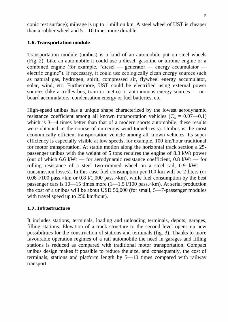
1.6. Transportation module
Transportation module (unibus) is a kind of an automobile put on steel wheels
(Fig. 2). Like an automobile it could use a diesel, gasoline or turbine engine or a
combined engine (for example, ―diesel — generator — energy accumulator —
electric engine‖). If necessary, it could use ecologically clean energy sources such
as natural gas, hydrogen, spirit, compressed air, flywheel energy accumulator,
solar, wind, etc. Furthermore, UST could be electrified using external power
sources (like a trolley-bus, tram or metro) or autonomous energy sources — on-
board accumulators, condensation energy or fuel batteries, etc.
High-speed unibus has a unique shape characterized by the lowest aerodynamic
resistance coefficient among all known transportation vehicles (Cx = 0.07—0.1)
which is 3—4 times better than that of a modern sports automobile; these results
were obtained in the course of numerous wind-tunnel tests). Unibus is the most
economically efficient transportation vehicle among all known vehicles. Its super
efficiency is especially visible at low speeds, for example, 100 km/hour traditional
for motor transportation. At stable motion along the horizontal track section a 25-
passenger unibus with the weight of 5 tons requires the engine of 8.3 kWt power
(out of which 6.6 kWt — for aerodynamic resistance coefficient, 0.8 kWt — for
rolling resistance of a steel two-rimmed wheel on a steel rail, 0.9 kWt —
transmission losses). In this case fuel consumption per 100 km will be 2 liters (or
0.08 l/100 pass.×km or 0.8 l/1,000 pass.×km), while fuel consumption by the best
passenger cars is 10—15 times more (1—1.5 l/100 pass.×km). At serial production
the cost of a unibus will be about USD 50,000 (for small, 5—7-passenger modules
with travel speed up to 250 km/hour).
1.7. Infrastructure
It includes stations, terminals, loading and unloading terminals, depots, garages,
filling stations. Elevation of a track structure to the second level opens up new
possibilities for the construction of stations and terminals (fig. 3). Thanks to more
favourable operation regimes of a rail automobile the need in garages and filling
stations is reduced as compared with traditional motor transportation. Compact
unibus design makes it possible to reduce the size, and consequently, the cost of
terminals, stations and platform length by 5—10 times compared with railway
transport.

6
Fig. 2. High-speed passenger module: a) external view; b) salon.
Capacity — 25 passengers; Estimated travel speed — 250 km/hour;
Design (maximum) speed — 300 km/hour;
Drive — internal combustion engine (diesel) with 120 kWt capacity;
Fuel consumption (diesel fuel) at cruising speed (250 km/hour) — 12 l/100 km.
Fig. 3. Station combined with anchor support and UST turning angle
b)
a)
7
1.8. Project solutions
UST track structure and supports are designed as a transportation elevated road in
accordance with Russian construction norms and rules (SNiP 2.05.03-84 ―Bridges
and pipes‖) as well as with the basic provisions for bridge standards of the USA
and EC countries, therefore, no certification is required. Each designed UST route
like any other transportation facility is subject to the expertise of relevant state
authorities.
1.9. UST operation
Lower contact voltage in the ―wheel — rail‖ pair (50—60 kgs/sq. mm against
100—120 kgs/sq. mm in railways), the rail-head wear will be less intensive than in
railway transportation (1 mm wear of the rail height after 100 million tons of train
load). The rail-head thickness is estimated for the whole service life period of UST
(50—100 years), for example the head thickness of 20—25 mm will be enough to
handle the total volume of traffic amounting to 500 million tons.
Operation costs are only associated with periodical protection of metal components
against corrosion (once per 10—20 years). With a string-rail body made of
stainless steel and supports – made of reinforced concrete the operation costs of a
route will be reduced to seasonal inspection of structural components (to reveal
construction defects and external damages).
1.10. Approbation
Building technology used for the track structure and supports as well as the basic
UST nodes and elements were exposed to successful approbation in 2001—2005
using a single-track testing unit built in Russia (town of Ozyory, Moscow Region,
Fig. 4). The key unit characteristics are as follows: length — 150 m, summary
string stress — 450 ts (at +20°C), height of supports — up to 15 m, maximal span
— 48 m, maximal mass of the moving load — 12 t, relative rigidity of the largest
span above the load — 1/1,500, metal-consumption of a track structure — 120
kg/m, route slope — 100‰.
The following components were investigated at the testing unit:
various strings (twisted cables with 27 mm and 15.2 mm diameter made of
wire with 3 mm and 5 mm diameter, respectively);
string anchorage (wedge clips that ensure safe cable fastening — in
laboratory tests cables were broken at stress of 24—28 tons everywhere but
not in clips);
relaxation of pre-stressed strings (relaxation of K-7 cable with 15.2 mm
diameter, with its estimated stress — 10,400 kgs/sq. cm not fixed during 4
years);
8
pile, drilling-injected and slab foundations of intermediate supports (height
2, 5 and 8 meters) and anchor supports (height — 1 and 15 m);
special high-strength concrete for string-rails (modified by plasticizer and
corrosion inhibitor);
two-rimmed steel wheel, damped with a rubber gasket between the wheel
rim and nave (showed safety and stability of movement — during 4 years of
operation no contact between the rim and rail head was observed which is
attributed to the fact that toroidal bearing surface of a wheel is responsible
for standard moving regime);
wheel-rail cohesion (minimal friction coefficient in the ―wheel — rail‖ pair
for raining or icing conditions is 0.15—0.2 enabling design of high-speed
UST routes with prolonged slopes up to 150—200‰;
blocking system of front wheels and link rod against turning;
correctness of estimates of the stability and rigidity of supports, track
structure and strings under the impact of dynamic loads of the rolling stock,
seasonal changes of temperature, wind, icing, etc.
2. Layout scheme of UST route
Layout scheme of UST route: ―Abu Dhabi — Dubai — Sharjah‖ is given in fig. 5.
It is proposed to install the track structures of a double-track route on isolated
supports with the height of 3—6 m and more which makes it possible to trace each
track independently at the distance of 5—10 m from each other and more. It will
contribute to the growing comfort of travel (no oncoming vehicles will be seen
from unibus windows) and safety of the transportation system (for example, its
resistance to terrorist acts will be increased because it is more difficult to
simultaneously put out of action two transportation lines installed on separate
supports at certain distance from each other).
Optimal length of spans at dry land sections is 20—40 m, at marine sections —
40—60 m (at sea depth up to 10 m) and 80—100 m (at sea depth up to 20 m).
Layout alternatives for UST routes coming along dry land and sea coastal areas are
given in fig. 6—8.

9
Fig. 4. UST testing unit in the town of Ozyory, Moscow Region, Russia
Fig. 5. Layout alternative of UST route ―Abu Dhabi — Dubai — Sharjah‖

10
Fig. 6. High-speed UST route in a desert
Fig. 7. High-speed UST route on a sea coast
Fig. 8. High-speed UST route passing though a settlement

11
3. Technical and economic characteristics of a double-track high-speed UST route “Abu Dhabi — Sharjah”
Purpose — freight/passenger route
Length — 138 km
Cost — USD 280 million (see table 1)
Estimated travel speed of transportation modules — 250 km/hour
Travel time — 37 minutes (see table 2)
Average height of supports — 5 m
Average length of spans — 30 m (50 m for marine sections)
Maximum (design) carrying capacity of a double-track route:
passengers — 100 million passengers/year
freights — 50 million ton/year
Expected passenger turnover (138 km section) — 12 million pass./year
Expected freight turnover (138 km section) — 3 million ton/year
Table 1
Approximate cost of UST route ―Abu Dhabi — Sharjah‖
Name of route components Number
(volume
of
works)
Cost per
1 unit
of work,
thous. USD
Total cost,
thous. USD
1. Transportation line, total,
including:
138 km — 130,000
1.1. Track structure 138 km 450 62,100
1.2. Foundation and supports 138 km 400 55,200
1.3. Technical control system to check the
state of supports and track structure
138 km
20
2,760
1.4. Radio-relay system of traffic control 138 km 40 5,520
1.5. Miscellaneous — — 4,420 2. Cost of infrastructure, total, including:
— — 45,000
2.1. Stations 3 units 6,000 18,000 2.2. Freight terminals 3 units 4,000 12,000 2.3. Depot and repair shops 1 unit 8,000 8,000 2.4. Miscellaneous — — 7,000 3. Rolling stock, total, including:
— — 32,000
3.1. Passenger modules 90 units 110 9,900 3.2. Freight modules 220 units 80 17,600 3.3. Emergency reserve modules 10 units 110 1,100

12
Name of route components Number
(volume
of
works)
Cost per
1 unit
of work,
thous. USD
Total cost,
thous. USD
3.4. Technical control modules to check the state of the route and to provide its emergency service
5 units
150
750 3.5. Miscellaneous — — 2,650 4. Rise in price of the route at difficult sections (passing through the city area, sea, crossing with communications) 30 km 800 24,000 5. Engineering/survey and design works for the route 150 km 40 6,000 6. Project/design works for the track structure, supports, rolling stock, infrastructure and control systems — — 20,000 7. Miscellaneous and unforeseen costs — — 23,000
Total: — — 280,000
3.1. Expected passenger flow
1 trip per year (to and from) for each citizen of the country and each tourist to give
the total of 12 million passengers per year (2 trips × (3 million persons + 3 million
persons)).
3.2. Expected freight flow
Approximately 1 ton of freight per year per 1 resident of UAE to give the total 3
million tons of freight per year.
3.3. Organization of traffic
For small volumes of traffic such as at the route ―Abu Dhabi — Sharjah‖ (12
million pass./year or 32,900 pass./per day or on the average 2,050 pass./hour at
two-shift operation) it would be economically feasible to use passenger and freight
modules of medium capacity and medium mass – about 5 tons in loaded condition.
It will make it possible to reduce the normative tension of strings in the track
structure and, consequently, to reduce the cost of UST route. In this case the total
carrying capacity will not be reduced, moreover, it will have a growth potential
to100 million pass./year.
Transportation (passenger and freight) module has as its drive a diesel (low-noise
impact, economically efficient, meets Euro-4 requirements in terms of emissions)
and an automatic gear box. Module is controlled by a driver. At the present stage

13
the use of fully-automatic system to control each module or transportation flow as
a whole would not be reasonable. Automatization of control could result in the
sharp rise in the cost of the rolling stock and transportation lines whereas the
number of servicing staff will not be reduced and no pay-roll savings could be
achieved. It could be attributed to the fact that like an airliner a unibus should have
on its board at least one professionally trained staff member responsible for the
operation of the rolling stock (in the former case — a driver additionally
performing functions of a steward, guide, etc. and in the latter case — a steward
performing, if necessary, functions of a driver, for example if the automatic system
of control is put out of action).
3.4. Transportation module requirements
1. Passenger modules (with 25 passenger capacity).
At two-shift operation one module will make 24 runs per 24 hours. At loading
coefficient of 0.8 and utilization coefficient of 0.8 one module could carry 384
passengers per 24 hours or 140,000 passengers per year. For transportation of 12
million passengers per year it will be necessary to have 86 modules.
2. Freight modules (carrying capacity — 3 tons)
One module will make 20 runs per 24 hours. At loading coefficient of 0.8 and
utilization coefficient of 0.8 one module will carry 38 tons of freight per 24 hours
or 14,000 tons per year. For transportation of 3 million tons of freight per year it
will be necessary to have 214 freight modules.
3.5. Travel time and circulation along the route
Travel time for a passenger trip from the centre of Abu Dhabi to the centre of
Sharjah will be 37 minutes (see table 2).
Table 2
No. Name of transportation process Time, min.
1 Waiting time for loading 1
2 Loading of passengers 1.5
3 Waiting for a trip 0.5
4 Acceleration to the speed of 250 km/hour 1.5
5 Movement along the route 28
6 Braking of a transportation module 1.5
7 Entry to the station 0.5
8 Unloading of passengers 1.5
9 Unforeseen time costs 1
Total: 37

14
At the aforementioned utilization and loading coefficients of the rolling stock the
total number of passenger modules simultaneously circulating along the route will
amount to 86 vehicles. With the track length of 2 × 138 km = 276 km the average
distance between the neighbouring passenger modules moving along the route at
the estimated travel speed will be 3,200 m and time interval of module circulation
— 46 sec.
Circulation of unibuses could be arranged as single vehicles or as a group, for
example, of 5 modules with interval of 5 sec. (or at distance of 350 m from each
other). In the latter case they will enter and depart from the station every 5 seconds,
therefore the platform length should enable simultaneous presence at the station of
5 modules. Intervals of circulation of such trains in which separate modules are
linked with each other not mechanically but by ―electronic coupling‖ will be 3.8
minutes.
Based on the optimal dynamic load conditions of a track structure unibuses moving
at high speed should be not closer than one span from each other. At the span
length of 50 m this distance will amount to 100 m, then maximum (design)
carrying capacity of the route ―Abu Dhabi — Sharjah‖ with 25-seat unibuses will
be as follows:
N max = 12,000,000 pass./year × (3,200 m/100 m) = 384,000,000 pass./year
For combined passenger and freight traffic the maximum carrying capacity of a
double-track route should be about 100 million pass./year and 50 million ton/year.
3.6. Annual income and operation profitability of the route
With the cost of passenger ticket ―Abu Dhabi — Dubai — Sharjah‖ being USD 6
(approximate net cost of travel is 1.5 USD/pass. or 0.011 USD/pass.×km) and
transportation tariff of USD 10 per 1 ton of freight (approximate net cost of
transportation is 3.5 USD/t or 0.025 USD/t.×km) the annual profit from the track
operation will be as follows:
D = 12,000,000 pass. × (6 – 1.5) USD/pass. + 3,000,000 t × (10 – 3.5) USD/t =
USD 73,500,000
At such annual profit it will be possible to pay back the costs during approximately
5 years. With the cost of a passenger ticket amounting to USD 10 recoupment time
will be about 3 years.
Specific capital investments per 1 km of a high-speed route (including
infrastructure, passenger and freight rolling stock) will amount to 2.03 million
USD/km.
15
The total profitability of the route operation depending on the tax rates will amount
to about 300% including:
a) profitability of freight traffic — approximately 250%;
b) profitability of passenger traffic — approximately 350%.
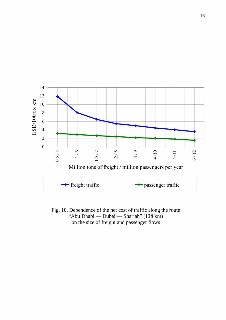
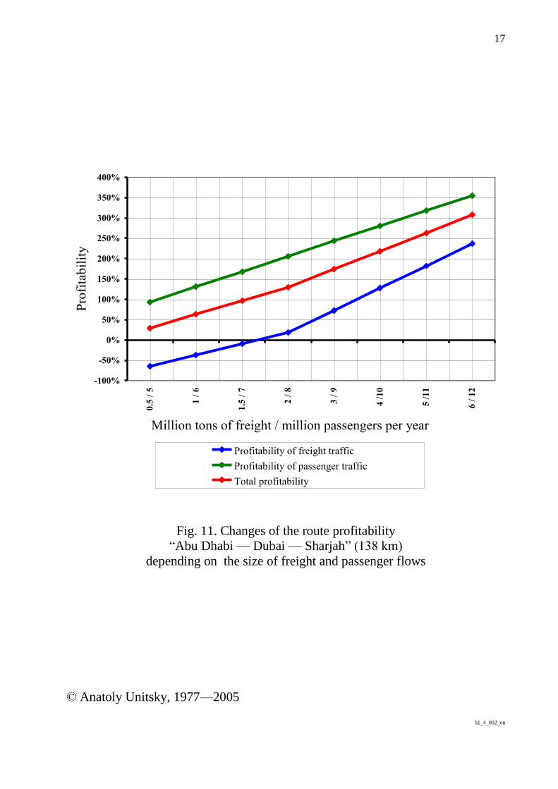
3.7. Comparative technical and economic indices of the route depending on
the size of freight and passenger flows
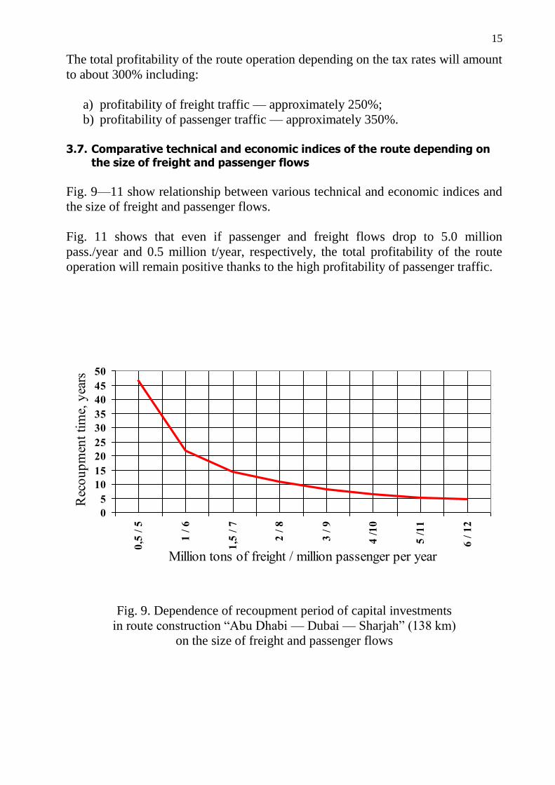
Fig. 9—11 show relationship between various technical and economic indices and
the size of freight and passenger flows.
Fig. 11 shows that even if passenger and freight flows drop to 5.0 million
pass./year and 0.5 million t/year, respectively, the total profitability of the route
operation will remain positive thanks to the high profitability of passenger traffic.
0
5
10
15
20
25
30
35
40
45
50
0,5
/ 5
1 /
6
1,5
/ 7
2 /
8
3 /
9
4 /
10
5 /
11
6 /
12
Million tons of freight / million passenger per year
Rec
ou
pm
ent
tim
e, y
ears
Fig. 9. Dependence of recoupment period of capital investments
in route construction ―Abu Dhabi — Dubai — Sharjah‖ (138 km)
on the size of freight and passenger flows
16
0
2
4
6
8
10
12
14
0.5
/ 5
1 /
6
1.5
/ 7
2 /
8
3 /
9
4 /
10
5 /
11
6 /
12
Million tons of freight / million passengers per year
US
D/1
00
t х
km
freight traffic passenger traffic
Fig. 10. Dependence of the net cost of traffic along the route
―Abu Dhabi — Dubai — Sharjah‖ (138 km)
on the size of freight and passenger flows
17
-100%
-50%
0%
50%
100%
150%
200%
250%
300%
350%
400%
0.5
/ 5
1 /
6
1.5
/ 7
2 /
8
3 /
9
4 /
10
5 /
11
6 /
12
Million tons of freight / million passengers per year
Pro
fita
bil
ity
Profitability of freight traffic
Profitability of passenger traffic
Total profitability
Fig. 11. Changes of the route profitability
―Abu Dhabi — Dubai — Sharjah‖ (138 km)
depending on the size of freight and passenger flows
© Anatoly Unitsky, 1977—2005
b1_4_002_en