structural behavior of circular holes in web elements of
TRANSCRIPT

Missouri University of Science and Technology Missouri University of Science and Technology
Scholars' Mine Scholars' Mine
Center for Cold-Formed Steel Structures Library Wei-Wen Yu Center for Cold-Formed Steel Structures
01 Aug 1996
Structural behavior of circular holes in web elements of cold-Structural behavior of circular holes in web elements of cold-
formed steel flexural members subjected to web crippling for end-formed steel flexural members subjected to web crippling for end-
one-flange loading one-flange loading
Craig Uphoff
Roger A. LaBoube Missouri University of Science and Technology, [email protected]
Wei-wen Yu Missouri University of Science and Technology, [email protected]
Follow this and additional works at: https://scholarsmine.mst.edu/ccfss-library
Part of the Structural Engineering Commons
Recommended Citation Recommended Citation Uphoff, Craig; LaBoube, Roger A.; and Yu, Wei-wen, "Structural behavior of circular holes in web elements of cold-formed steel flexural members subjected to web crippling for end-one-flange loading" (1996). Center for Cold-Formed Steel Structures Library. 104. https://scholarsmine.mst.edu/ccfss-library/104
This Technical Report is brought to you for free and open access by Scholars' Mine. It has been accepted for inclusion in Center for Cold-Formed Steel Structures Library by an authorized administrator of Scholars' Mine. This work is protected by U. S. Copyright Law. Unauthorized use including reproduction for redistribution requires the permission of the copyright holder. For more information, please contact [email protected].

CCFSS LIBRARY23 1 * 3860
1996
C2
Uphoff. Craig A.; ResearchAssistant LaBoube, Roger A.;STRUCTURAL BEHAVIOR OF CIRCULARHOLES IN WEB ELEMENTS OFCOLD-FORMED STEEL FLEXURALMEMBERS SUBJECTED TO WEBCRIPPLING FOR END-ONE FLANGE
CCFSS LIBRARY23 1 * 38601996
C2
Uphoff, Craig A.; ResearchAssistant LaBoube, Roger A.;STRUCTURAL BEHAVIOR OF CIRCULARHOLES IN WEB ELEMENTS OFCOLD-FORMED STEEL FLEXURALMEMBERS SUBJECTED TO WEBCRIPPLING FOR END-ONE FLANGE

Civil Engineering Study 96-2Cold-Formed Steel Series
Final Report
STRUCTURAL BEHAVIOR OF CIRCULAR HOLES IN WEB ELEMENTSOF COLD-FORMED STEEL FLEXURAL MEMBERS SUBJECTED
TO WEB CRIPPLING FOR END-ONE-FLANGE LOADING
by
Craig A. UphoffResearch Assistant
Roger A. LaBoubeWei-Wen Yu
Project Directors
August 1996
Department of Civil EngineeringUniversity of Missouri-Rolla
Rolla, Missouri

111
PREFACE
An experimental investigation of the web crippling limit state was conducted on single web
cold-formed steel flexural members with circular web openings in order to aid in the enhancement of
the current AISI (1986) Specification provisions for web crippling. The current AISI ASD
Specification (1986) and AISI LRFD Specification (1991a) have no specific design provisions for the
reduction in web crippling capacity of flexural members caused by the presence of web openings.
The test specimens, constructed ofC-sections, were subjected to a concentrated load applied
to one flange which satisfied the AISI criteria for End-One-Flange loading. The research findings
resulted in a new reduction factor equation which enveloped a wider range ofvalues for the cross
section geometric parameters. The previous reduction factor equation developed by Langan,
LaBoube, and Yu (1994) was originally developed for web openings that were rectangular with fillet
corners. During the analysis of the current study, the Langan, LaBoube, and Yu reduction factor
equation was found to be conservative for larger alh values. The new reduction factor results in an
equation to obtain the reduction in web crippling capacity for sections with web openings. The web
crippling capacity is considered for the web capacity without the effects of the bending moment.
The final conclusions resulting from the experimental investigation were used to develop
recommended design standards.
This report is based on a thesis presented to the Faculty of the Graduate School of the
University of Missouri-Rolla in partial fulfillment of the requirements for the degree of Masters of
Science in Civil Engineering.
Technical guidance for this investigation was provided by the American Iron and Steel

IV
Intstitute's Subcommittee on Stud Design: Perforated Elements. The Subcommittee's guidance is
gratefully acknowledged. Thanks is also extened to R. B. Haws, K. L. Slaughter, and S. P.
Bridgewater, AISI Staff, for their assistance.

•..•..........•........................................... X
v
TABLE OF CONTENTS
PREFACE•...•.•••••••••••••.•.....•••.•••••••••...••.•..........••.••. " 111
LIST OF ILLUSTRATIONS...•............................................ " IX
LIST OF TABLES
SECTION:
1. INTRODUCTION 1
A. GENERAL I
B. PURPOSE OF INVESTIGATION , 3
1. Primary Purpose 3
2. Secondary Purpose 3
C. SCOPE OF INVESTIGATION 4
1. Loading Condition 4
2. Cross-Section Types 4
3. Cross-Section Properties . . . . . . . 5
4. Range of a. Values 5
II. REVIEW OF LITERATURE 8
A. GENERAL 8
B. THEORETICAL ANALYSIS OF WEB CRIPPLING FOR COLD-FORMED STEEL FLEXURAL MEMBERS 8
C. PREVIOUS RESEARCH ON WEB CRIPPLING FOR SECTIONSWITH WEB OPENINGS 10
1. General 10

vi
2. Yu and Davis 10
3. Sivakumaran and Zielonka 12
4. Langan, LaBoube, andYu 14
5. Summary 16
D. PREVIOUS RESEARCH ON THE BEHAVIOR OFPERFORATED PLATE ELEMENTS AND WEBS OFFLEXURAL MEMBERS. . 17
1. General 17
2. Perforated Plate Elements 18
a. Narayanan and Chow 19
b. Yu 19
3. Perforated Web Elements of Flexural Members 20
a. Thick Web Flexural Members with Web Openings .. 20
b. AISC Guidelines 20
c. Thin-Walled Flexural Members with Web Openings. 22
E. DEVELOPMENT OF CURRENT AlSI SPECIFICAnONPROVISIONS FOR WEB CRIPPLING 24
1. General 24
2. Web Crippling Capacity 24
a. Sections with Edge Stiffened Flanges 24
b. Sections without Edge-Stiffened Flanges. . 25
F. AISI SPECIFICAnON PROVISIONS FOR WEB CRIPPLNG ... 26
1. General . . . . . . . . . . . . . . . . . . . . . . . . . . . . . . . . . . . . . . . . . . . 26
2. Web Crippling Capacity 26

vii
a. General 26
b. Web Crippling Equations 27
c. Influence ofHigh Fy Values 29
III. END-ONE FLANGE UNREINFORCED SINGLE WEB OPENINGSTUDy 31
A. INTRODUCTION 31
B. PURPOSE 31
C. EXPERIMENTAL INVESTIGATION 32
1. Test Specimens 32
2. Test Setup 34
3. Test Procedure 35
D. TEST RESULTS 36
I. General 36
2. Typical Failures 36
3. Web Crippling Deformation at Failure 36
E. EVALUATION OF TEST RESULIS 40
I. General 40
2. Effect of IX on Web Crippling Capacity 41
3. Effect of a/h on Web Crippling Capacity 41
F. EVALUATION OF LANGAN, LABOCBE. AND YUREDUCTION FACTOR EQUATION 41
I. General 41
2. Effect of Langan, LaBoube, and Yu RF Equation on High aihValues , 48

Vlll
3. Effect ofLangan. LaBoube. and Yu RF Equation on hitRatio 48
4. Summary ofThe Effect of ex. a/h. and hit on Web CripplingCapacity 49
G. DEVELOPMENT OF REDUCTION FACTOR EQUATIONS 501. General 50
2. Reduction Factor Equation with ex and a/h as IndependentVariables .. . . . . . . . . . . . . . . . . . . . . . . . . . . . . . . . . . . . . . . . . . . . 51
3. Reduction Factor Equation with ex. a/h. and hit asIndependent Variables 51
H. DESIGN RECOMMENDATIONS 55
1. Reduction Factor Equation 55
2. Limitations of Reduction Factor Equation 55
IV. CONCLUSIONS 58
V. FUTURERESEARCH 59
APPENDIX: CROSS-SECTIONAL PROPERTIES FOR TEST SPECIMENS 60
BffiLIOGRAPHY 65

IX
LIST OF ILLUSTRATIONS
Figure Page
1 Loading Condition Criteria 3
2 Typical Cross-Section Parameters 5
3 Typical Test Specimen Parameters 6
4 Typical EOF Test Specimens 33
5 Tinius Olsen Test Machine 35
6 Typical EOF Solid Web Specimen Failures 37
7 Typical EOF Web Crippling Failure with High a/h ratio and (X equal to 1 38
8 Out-of-plane Web View of Web Crippling Failure 39
9 Failure Load Applied to Specimen 40
10 Graphic Illustration of (X (x/h) vs. PSW for Current UMR Study 42
11 Graphic Illustration of aJh vs. PSW for Current UMR Study 42
12 Combined Graphical Illustration of PSW/Eq. 7 vs. a/h for Langan (1994) andCurrent UMR Studies. . 49
13 Combined Graphical Illustration of PSW/Eq. 7vs. hit for Langan (1994) andCurrent UMR Studies. . 50
14 Combined PSW/Eq. 19 vs. a/h of Langan (1994) and Current UMR Studies j 3
15 Combined PSW/Eq. 21 vs. a/h of Langan (1994) and Current CMR Studies ..... 54
16 Combined PSW/Eq. 19 vs. hit of Langan (1994) and Current UMR Studies 54
17 Combined PSW/Eq. 21 vs. hit of Langan (1994) and Current UMR Studies 55

x
LIST OF TABLES
Page
I. Cross-Sectional Properties for EOF Test Specimens 7
II. Unreinforced Web EOF Cross-Section Parameter Ranges 7
III. Unreinforced EOF Test Results , .43
IV. Statistical Analysis and Comparison of Reduction Factor Equations 53

I. INTRODUCTION
A. GENERAL
An environmental concern regarding the use of wood being an appropriate
construction material has become a contemporary issue. The depletion of forests, caused not
only by the building construction industry, but also by natural disasters such as forest fires,
has raised many questions about the conservation of the environment. Trees are being re
planted in an effort to make up for the loss, but trees take many years to mature.
Therefore, in an attempt to improve the environment and the feasibility of building
construction, alternative materials for residential construction are being investigated. One
material that is being researched extensively is cold-fonned steel. Cold-fonned steel has
many advantages over other building materials. The foremost advantage is its recyclability,
which is an environmentally attractive advantage. Other advantages ofcold-fonned steel are
that it has a very high weight-to-strength ratio, construction is fast and easy, it can be mass
produced with consistent cross-sectional properties, it is tennite proof and rotproof, it is
economic in transportation and handling, and it is noncombustible. Cold-fonned steel has
been preferred in light-industrial construction for many years because it is cost competitive
and because of the aforementioned advantages.
The use of cold-fonned steel members in building construction began around the
1850's in the United States and Great Britain. Although cold-formed steel building
construction began in the 1850's, cold-fonned steel was not widely used until around 1940.
Since 1946 the use and the development of thin-walled cold-formed steel
construction in the United States have been accelerated by the printing of the Specification

2
for the Design ofCold-Formed Steel Structural Members of the American Iron and Steel
Institute (AISI). Each subsequent edition incorporates investigation results which have
improved the completeness and surety of the specification. For example, based on a study
by Hetrakul and Yu (1978), the 1980 edition underwent expansive refinement in the design
ofbeam webs subjected to web crippling and the combination ofbending and web crippling.
However, the web crippling provisions and combined bending and web crippling provisions
of the 1980 and subsequently revised editions of the Specification pertain only to flexural
members without web openings.
Since 1990, the University ofMissouri-Rolla has conducted a comprehensive study
of the behavior ofweb elements offlexural members with web openings subjected to loads
causing bending, shear, and web crippling, and combinations thereof. The current AISI ASD
Specification (1986) and AISI LRFD Specification (1991a) have no provisions for the
possible degradation in strength for the various limit states of flexural members caused by
the presence of web openings. The use of members with web openings spaced at intervals
along the longitudinal axis of the section provides passages for conduits frequently used in
building construction.
The most significant reason for conducting this research investigation was the
concern that the presence of web opening(s) would have a degrading effect on the web
crippling behavior of flexural members. Therefore, the effect of a web opening must
be defined, and if necessary, recognized by the AISI Specification provisions.

3
B. PURPOSE OF INVESTIGATION
This research investigation had the following two purposes:
1. Primary Pm:pose. The primary purpose of this investigation was to study the
structural behavior ofsingle web cold-formed steel flexural members with unreinforced web
openings subjected to web crippling for End-Qne-Flange (EOF) loading condition (Figure
1). Design recommendations were developed which consider the web crippling limit state
and EOF loading. The primary consideration of structural behavior was the failure load of
the test specimens. This failure load quantified the web crippling strength.
Figure 1 Loadmg Condltlon Cntena
I I I I,- dl~ ,...---- d2 ---------,
I I I II I I
:~I I II I I
~u ___1I I tI II "_ II II IJ _____
T-
h = D - 2 (R+t)
Loading Condition End or Interior Qne or Two Flanged l d2
End-Qne-Flange, EQF < 1.5h > 1.5h
Interior-One-Flange,IOF 2: 1.5h > 1.5h
End-Two-Flange, ETF < 1.5h S 1.5h
Interior-Two-Flange, ITE > 1.5h S 1.5h. ..
2. Secondaty Purpose. The secondary purpose of the investigation was to evaluate
the adequacy ofthe current AlSI provisions and conclusions from previous studies for single
web sections based on the results of the unreinforced EOF tests performed during the

4
investigation. In order to perform this evaluation, a comparison of test results for specimens
with no web openings was performed to make sure there was a good correlation with the
current AISI provisions. Then, a comparison oftest results for specimens with web openings
was performed to determine if the current AISI provisions could adequately predict the web
crippling capacity of sections with web openings. Finally, a comparison of test results for
specimens with web openings was performed to determine the adequacy of the reduction
factor developed by Langan, LaBoube, and Yu (1994) for rectangular holes with fillet
comers.
C. SCOPE OF INVESTIGATION
The elements ofthe scope of the investigation can be grouped into the following four
areas: 1. loading condition, 2. cross-section types, 3. cross-section properties, and 4. range
of a values. The characteristics of each test specimen enable categorizing into one of the
four areas.
1. Loadin~ Condition. End-One-Flange loading condition was used, and the criteria
for this condition is illustrated in Figure 1. The reduction factor equation developed for EOF
loading condition is valid only for the EOF loading condition.
2. Cross-Section Types. All cross sections tested were C-shaped sections with edge
stiffened flanges. However, the same web crippling behavior will exist for other single web
elements with unstiffened flange~. Therefore, the recommendations for the EOF reduction
factor equation are valid for other single web cross-section shapes, with or without stiffened
flanges.

5
3. Cross-Section Properties. Table I provides the properties ofthe EOF unreinforced
web test specimens and Table II gives the ranges of parameters of tests. The type of web
openings that were used in this investigation were circular in shape and were located at mid-
height of the test specimen. Figure 2 illustrates a typical cross-section used in this
investigation.
4. Ran~e of ex Values. The value of ex varied from 0 to 1 for the unreinforced EOF
tests. The parameter ex is equal to the longitudinal clear distance between the edge of the
bearing and the web opening, x, divided by the height ofthe flat portion ofthe web, h (Figure
3).
---8~--
o
~l_~ V~R JJL._~~_~_
Figure 2 Typical Cross-Section Parameters

L/2
[~
CJb.
N x a I 3.0.
Figure 3 Typical Test Specimen Parameters (a = x/h)
6

Table I Cross-Sectional Properties for End-One-Flange Test Specimens
Specimen D R t b B dr a Fy bIt alb Rtt NIt(in.) (in.) (in.) (in.) (in.) (in.) (in.) (in.)
EOF-C8-16 7.938 0.219 0.056 7.388 1.625 0.438 0,2,4,6 56.8 132.1 ---- 3.918 17.889
EOF-C8-20 7.920 0.172 0.034 7.509 1.650 0.500 0,2,4,6 47.0 224.1 ---- 5.134 29.851
EOF-C6-16 6.017 0.188 0.056 5.530 1.625 0.438 0,2,4 69.4 98.3 ---- 3.336 17.794
EOF-C6-20 7.938 0.172 0.033 5.961 1.625 0.438 0,2,4 55.3 169.8 ---- 5.256 30.581
Table II Unreinforced Web EOF Cross-Section Parameter Ranges
b t Fy N a a alb hit Rtt NIt(in) (in) (ksi) (in) (in)
minimum 5.961 0.033 47 1 0.0 0.00 0.266 98.4 3.336 17.794
maximum 7.509 0.056 56.8 I 1.0 6.00 0.812 224.1 5.256 30.581
-...J

8
II. REVIEW OF LITERATURE
A. GENERAL
The following topics pertain to and are applicable to the investigation of web
crippling for the EOF loading condition:
1. Theoretical analysis of web crippling for cold-fonned steel flexural members.
2. Previous research on web crippling behavior for sections with web openings.
3. Previous research on the behavior of perforated plate elements and webs of flexural
members.
4. Development of current AISI Specification provisions for web crippling and combined
web crippling and bending.
5. AISI Specification provisions for web crippling, bending, and combined bending and
web crippling.
6. Langan, LaBoube, and Yu reduction factor equations for web crippling of unreinforced
single web members with web openings.
B. THEORETICAL ANALYSIS OF WEB CRIPPLING FOR COLD-FORMED STEEL
FLEXURAL MEMBERS
In using theoretical mechanics of defonnable and ductile materials, the prediction of
web crippling behavior of cold-fonned steel flexural members is very difficult as
summarized by Yu (1991):

9
...the theoretical analysis of web crippling for cold-formed steel flexuralmembers is rather complicated because it involves the following factors:
I. Nonuniform stress distribution under the applied load and adjacentportions of the web.
2. Elastic and inelastic stability of the web element.3. Local yielding in the immediate region of load application.4. Bending produced by eccentric load (or reaction) when it is applied on the
bearing flange at a distance beyond the curve transition of the web.5. Initial out-of-plane imperfection ofplate elements.6. Various edge restraints provided by beam flanges and interaction between
flange and web elements.7. Inclined webs for decks and panels.
Because ofthe above complexities, the current AISI Specification (1986) provisions
for web crippling were initially based on the experimental investigations perfonned at
Cornell University by Winter and Pian (1946), and by Zetlin in the 1940's and 1950's
because of the difficulties stated above. The current AISI Specification (1986) is based on
a study performed at the University of Missouri-Rolla (UMR) by Hetrakul and Yu (1978).
In both the Cornell and UMR investigations, the web crippling tests were carried out under
four loading conditions; (1) End-One-Flange (EOF) loading, (2) Interior-One-Flange (lOF)
loading, (3) End-Two-Flange (ETF) loading, and (4) Interior-Two-Flange (ITF) loading.
The loading conditions are defined in Figure I.
Hetrakul and Yu (1978) and Santaputra and Yu (1986) presented a summary of
previous theoretical research for the study ofthe web crippling behavior of solid web flexural
members. Both of these investigations provide equations that address web crippling
behavior and combined bending and web crippling behavior; however, the equations
provided were strictly empirical and were not based on theoretical analysis. The Hetrakul
and Yu equations were adopted by the AISI Allowable Stress Design (ASD)Specification
(1986) and AISI Load and Resistance Factor Design (LRFD) Specification (199Ia).

10
Santaputra and Yu (1986) provide results usmg the finite element program
"Automatic Dynamic Incremental Nonlinear Analysis" (ADINA) to investigate the web
crippling behavior ofhat-shaped solid web sections. They provide information concerning
their modeling of the section to include the discretizing of the domain, the loading and
boundary conditions, the material properties, and the geometric non-linear characteristics of
the deformation. Analytical results were compared to experimental test results for
determining the ultimate capacity, and the results were within 21 and 23 percent of the web
crippling capacity. As concluded by Santaputra and Yu (1986), "The desired design
expressions (for predicting web crippling capacity) have to be developed experimentally."
C. PREVIOUS RESEARCH ON WEB CRIPPLING FOR SECTIONS WITH WEB
OPENINGS
1. General. There is limited research on the web crippling behavior of sections with
web openings. Yu and Davis (1973), Sivakumaran and Zielonka (1989), and Langan.
LaBoube and Yu (1994) performed investigations on the web crippling behavior of cold
formed steel flexural members with web openings. All of these investigations will be
discussed in this review.
2. Yu and Davis. Yu and Davis (1973) provided the results for 20 IOF web crippling
tests conducted on cold-formed steel members. The tests specimens that were used were
composed of two channels with square or circular web openings. The web openings were
placed at mid-height of the web and were longitudinally centered on the IOF load plate. The
channels were constructed by connecting them back-to-back, as I-beams, or connected
through the simple lip edge stiffeners. The depth to thickness ratios ranged from 66.7 to 101,

11
the web opening depth-to-web ratio ranged from 0 to 0.641, and Fy values ranged from 57.9
to 70.7 ksi. The tests were performed with a constant bearing length of 3.5 inches. The
failure loads were the only recorded results, and therefore were the primary measure of the
web crippling limit state. The research was preliminary in nature and was intended to
provide design information for engineers.
Two reduction factor equations were provided by Yu and Davis (1973) which are
distinguished from each other by whether or not the web opening is square or circular. The
reduction factor, RF, for circular web openings with O:s d/h:s 0.5 is as follows:
where
dRF=l.O -0.6
h
d = diameter of the circular web opening
(1)
h = clear distance between flanges measured in the plane of the web
The equation for square web openings with 0 :s hjh :s 0.642 is as follows:
where
hRF=1.0 -O.77-!.
h
h. = width of the square web opening
(2)
h = clear distance between flanges measured in the plane of the web
Equations 1 and 2 have no restriction on the value of the bearing length for
applicability of the equations. In the limiting case of a value of d or h. equal to zero, the
reduction factor equations, for both Equations 1 and 2, produce a value of unity, therefore
no capacity reduction is required.

12
The effects of a square web opening are more pronounced in reducing the web
crippling buckling load, as can be seen by a comparison of the coefficients of the second
terms of both reduction factor equations. The increased localized stress and the removal of
a greater amount ofmaterial for square openings resulted in a greater tendency for the square
hole to cause buckling at a lower web crippling load.
3. Sivakumaran and Zielonka. Sivakumaran and Zielonka (1989) developed a
reduction factor equation for sections with web openings subjected to IOF loading:
where
RF=[l-O.197(-~i][l-O.127(~)2]h n\
nj = N + h - a
N = bearing load length
h = flat height of web
a = height of web opening
b =longitudinal length of web opening
(3)
Limits of Equation 3 are: blnj ~ 2.0, and a/h ~ 0.75
Equation 3 is always less than unity for sections with web openings. This reduction
factor equation was developed based on the results of 103 tests with the web opening
centered on the longitudinal location of the load plate. This experimental research was
performed on C-shaped, edge-stiffened, channel sections subjected to IOF loading condition,
and having rectangular web openings at mid-height of the web. The value ofN was equal
to 2.0 inches for all of the tests.

13
Sivakumaran and Zielonka (1989) state, "The bending moments associated with the
present tests were calculated and were compared to the corresponding moment capacity of
the section and the effects we found negligible." The effect of bending moment interaction
will occur when "'bending moments higher than 30% of moment capacity of the section
influence [degrade] the web crippling strength." Bending and web crippling did not interact
because the simply supported test specimens used by Sivakumaran and Zielonka (1989) had
short span lengths, therefore insignificant bending moment was created in the specimen at
the mid-span region of the web opening and web crippling failures. The reduction factor
equation was based on the assumption that the distribution of the load occurs at a 45 degree
angle.
Sivakumaran and Zielonka (1989) subsequently evaluated the performance of
Equation 3 by use of the ratio of the predicted capacity, using the reduction factor equation,
to the tested capacity. Ninety-six percent ofthe ratio values ranged between 0.9 and 1.1. Or,
in the terminology of the current investigation, 96 percent of the test results satisfied the
following relationship:
RF x (Pn)testsolid web 10.9 ~ ~ l.
(P n)test,web opening
(4)
A proposal by LaBoube (1990a) was made to use a modified form of the
Sivakumaran and Zielonka reduction factor equation as a provisional design recommendation
to account for web openings:

14
Where, D =total depth of the section
(5)
and the remaining parameters are the same as for Equation 3.
4. Lanian. LaBoube. and Yu. A study on the web crippling behavior of single
unreinforced webs for cold-formed steel flexural members with web openings subjected to
EOF loading condition, Figure 1, was conducted and reduction factor equations were
developed that account for the degradation in web strength due to the presence of web
openings.
The test specimens were constructed of C-shaped sections with edge stiffened
flanges. The web openings were rectangular with fillet comers and were located at mid-
height of the web. Two sizes of web openings were used in the Langan, LaBoube, and Yu
(1994) experimental investigation, 0.75 x 2 inches and 1.50 x 4 inches, and are designated
by dimensions a and b, where a is the height of the web opening and b is the longitudinal
dimension of the web opening. Tests were conducted for (X values in increments ofO. 0.5,
0.7, 1.0, and 1.5. The non-dimensional value of (X is the ratio x/h, where x is the longitudinal
distance from the bearing edge to the edge of the web opening and h is the height of the flat
portion of the web.
Langan, LaBoube, and Yu (1994) conducted 157 tests during their investigation of
which, 108 failed in web crippling, 34 failed in shear, 4 failed by flexure at mid-span in the
compression flange, and II were conducted to perform diagnostic tests to ensure the validity
of the testing procedure. The primary measure of the effect of the web openings on web

15
crippling behavior was the failure load of the test specimens. Langan, LaBoube, and Yu
(1994) detennined the degradation of web strength was associated with the specimen
parameters of a/h and a.
Langan, LaBoube, and Yu (1994) concluded that since the test specimens were
configured as simply supported spans, zero moment is considered to have been present at the
EOF failure locations. Therefore, the interaction of bending was not considered for the test
specimens.
Seventy-eight tests were conducted in which all failed due to the web crippling limit
state. A bivariate linear regression was performed on the 78 test results with a and aIh as
the independent variables. The resulting reduction factor equation, with a maximum limit
of 100%, was found to be:
RF=107.91-(62.95~)+(12.06a) ~ 100%h
or,
RF=1.08-(0.630~)+(0.120a) ~ 1.00h
(6)
(7)
Equation 7 is applicable to all cross sections and conditions that meet the ranges of
applicability: (1) the limits imposed on the existing Specification web crippling provisions,
(2) the industry imposed limits on web opening parameters, (3) engineering judgement, and
(4) the range ofparameters for the test specimens provided by the Langan, LaBoube, and Yu
(1994) experimental investigation.

16
5. Summary. The following conclusions result from the investigations by Yu and
Davis (1973), Sivakumaran and Zielonka (1989), and Langan, LaBoube, and Yu (1994):
1. The experimental investigation can be accomplished at a single bearing length value, N.
11. The effect ofbending moment on the web crippling limit state for EOF loading condition
is negligible.
lll. There is precedence for the development and use of reduction factor equations as
applicable to web crippling behavior of cold-formed steel sections with web openings.
It is possible to develop reduction factor equations which relate the strength of a section
with web openings to the strength of its solid web counterpart. The development and
use of this reduction factor equation has the following characteristics:
(a) It is based strictly upon statistical analysis of experimental results, and therefore
is empirical.
(b) It incorporates non-dimensional measures of the size of the web.
(c) It is not limited for use at the N value used in the testing, nor must the value of
N be incorporated into the reduction factor equation as a parameter. The
primary influence of the N value is maintained by its inclusion in the equation
which provides the predicted capacity of the solid web cross section.
(d) It is based on the ultimate capacity of the test specimens in the absence of
significant bending moment.
(e) No stress level or serviceability requirements are imposed.
(f) It obtains a value of unity as the web opening approaches zero.
(g) It has limits for applicability based on cross-section parameters used during the
testing procedure and on engineering judgement. The limits include the

17
maximum value of the ratio of the web opening height to height of the web, and
a non-dimensional limit on web opening length.
(h) The testing procedure has variable centerline locations of the web opening
relative to the bearing reaction plates, therefore, the reduction factor equation
contains a parameter which considers the relative locations of the web
openings with respect to the bearing reaction plates. In keeping with the
convention of other parameters in the reduction factor equation, this parameter
is non-dimensional.
D. PREVIOUS RESEARCH ON THE BEHAVIOR OF PERFORATED PLATE
ELEMENTS AND WEBS OF FLEXURAL MEMBERS.
1. General. A number of investigations have been performed on the effect of
openings or perforations in structural elements and members. This research incorporates
combinations of analytical and experimental investigations, and the research can be
categorized into two general areas: research performed on perforated plate elements, and
research performed on flexural members with web openings.
In order to adequately investigate web crippling behavior of flexural members with
web openings, the following two conditions must exist. First. the testing procedure must be
performed on flexural members, instead ofplate elements. Second, the load must be applied
to the flanges of the flexural member in the vicinity of the web opening, else web crippling
in the vicinity of the web opening is precluded. Otherwise, the results, though useful in
providing generalities and trends, do not thoroughly incorporate the complexities of web

18
crippling behavior. Therefore, it is concluded that research on plate elements does not
specifically address web crippling behavior of flexural members with web openings.
2. Perforated Plate Elements. Although webs offlexural members are typically plate
elements, the adoption of plate research to web crippling has limited value because of the
complexity ofthe loading boundary conditions which exist for the webs offlexural members.
The boundary conditions for plate research can be made ideal, i.e. the boundary conditions
are often created such that they satisfy the discrete conditions ofeither free, fixed, or simply
supported: whereas, a web of a flexural member typically does not satisfy any of these ideal
conditions. The web ofa flexural member is provided some degree of rotational stiffness by
the flanges, and the magnitude of the restraint is between that of the simply supported and
fixed conditions. Also, the support will vary depending upon the state of stiffness due to
elastic or plastic behavior.
Also, the loading conditions for plate research can be made ideal. The loading
conditions are often created such that they are either subjected to in-plane shear, flexure, or
normal forces, and each of these can be made to act in the absence of each other.
Conversely, it is difficult to categorize the loading conditions for the web of a flexural
member, which exists at the web and flange interface, into any of these ideal loading
condition types. Furthermore, unlike the known location of the edge of a plate, the location
of the boundary along the length of the web is unknown. Additionally, the large deflections
typically exhibited during web crippling analysis change the equilibrium relationship and the
resultant location of flange load application.

19
However, both the webs of flexural members and plate elements are susceptible to
the same general categories of limit states of strength, stability, and serviceability, for both
elastic and inelastic behavior.
a. Narayanan and Chow. Experimental research, performed by Narayanan and Chow
(1984), was conducted on the ultimate capacity and post-buckling behavior of perforated
steel plates. Narayanan and Chow provide design curves for perforated square plates with
either circular or square holes in the center of the simply supported plate subjected to
uniform compression. These curves provide an approximate method of evaluating the
ultimate capacity of the plates.
b. Yu. Yu (1991) discusses the structural behavior of perforated elements under
uniform stress, and provides an overview of plate buckling research for perforated plates
under an uniform state of stress at the plate boundaries. The research presented was
performed on flat plate elements with openings subjected to idealized loading and boundary
restraint conditions. For the research discussed, the loading conditions were limited to in-
plane normal, shear, and moment loads. The boundary restraint conditions were either fully
free, simple support, or fully restrained.
Because the web is a component element of flexural members, the overall behavior
of the flexural member is related to the behavior of the web element. Yu (1991) states:
For perforated cold-formed steel structural members, the load-carryingcapacity of the member is usually governed by the buckling behavior and thepost-buckling strength of the component elements. The critical bucklingloads for perforated plates and members have been studied by numerousinvestigators.

20
3. Perforated Web Elements ofFlexuraJ Members. A large munber of investigators
have performed analytical and verification test on the behavior of web elements with
openings of flexural members. The previous research performed on perforated webs of
flexural members avoided the web crippling limit state being influenced by the web
openings. This was accomplished insuring that the concentrated load was not located in the
region of the web opening and by providing few web openings in the member. Typically,
only one web opening was used.
a. Thick Web Flexural Members with Web Openings. A majority of the work on the
behavior of web elements of flexural members with web openings was performed on hot
rolled or composite sections. In these investigations, web crippling was not addressed.
Yu (1991) states, that the exact analysis and the design of steel sections having
perforated elements are complex, in particular when the shapes and the arrangement of the
elements are complicated. Even though limited information is available for relatively thick
steel sections, on the basis ofprevious research, these design criteria may not be applicable
completely to perforated cold-formed steel sections due to the fact that local buckling is
usually only a major concern for thin-walled members. Also, as stated by Chan and
Redwood (1974) for thick-walled sections, "Attention is restricted to stress analysis and it
is assumed that buckling does not occur."
b. AISC Guidelines. Much of the research conducted on thick web flexural members
with web openings was performed for the American Institute of Steel Construction (AISC).
Therefore, the AISC Guidelines (1990) provide a recent and brief summary of the research
performed on the effect of web openings on thick-walled sections and the practical
implementation of the results.

21
The purpose ofweb openings in thick-walled hot-rolled sections is generally the same
as those stated previously for cold-formed sections. However, due to the great differences
in the manufacturing process, web openings in thick-walled hot-rolled sections are placed
at only needed locations, instead of at 24 inch intervals along the longitudinal axis of the
member, as is the industry standard for cold-formed steel sections.
Furthermore, for thick-walled hot-rolled steel sections, the web openings can have
the minimum necessary size required to accommodate the conduit dimensions. In contrast,
for cold-formed steel construction, a design must use the next larger size of standard size
web opening, unless the opening is cut in the field.
The considerations included in the AISC Guidelines most closely related to the
concerns ofthe current study for thin-walled sections are provided in Section 3.7, Guidelines
for Proportioning and Detailing Beams with Web Openings. Section 3.7 provides guidelines
to ensure stability to preclude web buckling and buckling of the tee-shaped compression
zone. Additional considerations in Section 3.7 are provided for by relationships which
consider an equivalent circular opening for a rectangular opening, reinforcement of an
opening, and spacing requirements between openings.
For stability concerns, web crippling, due to the effect of a concentrated load being
transferred into the web in the area of a web opening, is precluded by either requiring a
conservative minimum distance between the concentrated load and the web opening, or by
requiring web reinforcement if this minimum distance is not achieved. The guidelines for
the placement of a concentrated load are given by AISC (1990) as follows:
Concentrated loads are not allowed over the opening because the design expressions
are based on a constant value of shear through the opening and do not account for the local
22
bending and shear that would be caused by a load on top of the tee. The requirements
represent an extension of the criteria as suggested by Redwood and Shrivastava (1980).
These criteria are applied to composite and non-composite members with and without
reinforcement. The requirement that openings be placed no closer than a distance d to a
support is to limit the horizontal shear stress that must be transferred by the web between the
opening and the support
c. Thin-Walled Flexural Members with Web Openings. Investigations have also
been performed using analytical and experimental research techniques on the flexural
behavior ofthin-walled rolled or welded plate elements with openings. This includes studies
by Redwood, Branda, and Daly (1978), and Redwood and Uenoya (1979). These
investigations on thin-walled elements were concerned with consideration of the open web
section as a flexural member subjected to concentrated loads, and the investigation of the
effect of the resulting shear and bending moment forces on the web elements in the vicinity
of the web opening. The emphasis was placed on the shear, moment, and shear-moment
interaction behaviors due to flexure. Although the web elements may buckle due to the
compressive stresses caused by the shear and flexural stresses, these investigations did not
specifically address web crippling behavior.
Typically, the location of the concentrated load was far from the web opening and
therefore, prevented web crippling in the area of the web opening. The loads, though not in
the vicinity of the web opening, were used to generate desired shear or moment regions in
the member in the area of the web opening.
In the portion ofthe member located in the area of the web opening, the compression
region of the cross-section behaved like a tee or angle section under compression because

23
of the free edge along the web opening. Therefore, the compression region of the web near
the web opening was highly susceptible to buckling. Due to the free edge along the web
opening, the section did not receive the restraint provided by the web material of the section
nearer the neutral axis or in the tension region of the web, as exists in unperforated web
sections. The buckling situation is different from web crippling which is caused by a
concentrated load applied to the section in the region of the web opening.
Redwood, Branda, and Daly (1978), state that the most critical factors influencing
the behavior of sections with web openings are:
1. The shear force at the hole
2. The moment at the hole centerline
3. The web slenderness
4. The slenderness of the web of tee sections formed by the part of the beam above
or below the hole
5. The length of the hole
6. The shape of the hole
7. The presence of transverse stiffeners near the hole.
General observations were provided for the situation when the web buckling did not
exist. These observations showed that the presence of the hole reduces the maximum values
of bending moment and shear force that can be applied to the beam in the region of the hole.
In the absence of shear, the plastic bending moment is reduced by 2 to 5%. In contrast, the
ultimate shear capacity is greatly reduced.

24
E. DEVELOPMENT OF CURRENT AISI SPECIFICATION PROVISIONS FOR WEB
CRIPPLING
1. General. The current provisions for web crippling and combined bending and web
crippling were adopted from an investigation by Hetrakul and Yu (1978), based on the
results of 224 web crippling tests conducted at Cornell University and University of
Missouri-Rolla. All tests were performed on solid web specimens, and the resulting
equations were intended for use on solid web sections.
The provisions reviewed in this section first appeared in the 1980 edition of the AISI
Specification. The resulting equations from the study by Hetrakul and Yu (1978) are based
strictly on statistical analysis of test results and therefore, are empirical.
2. Web Cripplin~ Capacity. Hetrakul and Yu (1978) provide equations for the
allowable web crippling capacity ofcold-formed steel members subjected to EOF, IOF, ETF,
and ITF loading conditions for single web of multiple web sections with or without edge-
stiffened flanges. The equations provide the maximum allowable web crippling capacity.
Since the equations compute the maximum allowable web crippling capacity a factor of
safety must be incorporated into the equations. The factor of safety for the equations of EOF
loading condition is 1.85 and is attributed for the common high variance found in web
crippling analysis. The equation which is applicable to the conditions for the current
investigation is for EOF loading and is provided as follows:
a. Sections with Ed~e Stiffened Flan~es.
For Nit ~ 60:
F h N(P ) =t2.2.C3CiI78.70-0.33-)(1 +0.0102-), kips
a camp 33 t t (8)

25
For Nit> 60:
b. Sections without Ed~e-Stiffened Flan~es.
For Nit::; 60:
F h N(P) =t 22C 3C4(l17.19-0.1S-)(1+0.0099-), kips
a comp 33 t t
For Nit> 60:
F h N(P ) =t 22C
3C
4(178.70 -0.33-)(0.706 +0.0 148-), kips
a comp 33 t t
(9)
(10)
(11)
Where, C3 =(1.33 - 0.33 FJ33)
C-/ = (1.15 - 0.15 R/t) ::; 1.0
F.v = Design yield stress of the web, ksi
h = Depth of the flat portion of the web, inches
t = web thickness, inches
R = Inside bend radius, inches
N = Bearing length of load or reaction, inches
The above equations for the EOF loading condition for single web members are
distinguished by whether or not the flange is unstiffened for edge-stiffened. This is done

26
because members with stiffened and unstiffened flanges have a considerable difference in
load-carrying capacities when looking at the web crippling limit state.
F. NSI SPECIFICATION PROVISIONS FOR WEB CRIPPLING
1. General. The provisions ofthe AISI Allowable Stress Design (ASD) Specification
and the NSI Load and Resistance Factor Design (LRFD) Specification are reviewed in this
section. The areas of the provisions reviewed in this paragraph pertain to the web crippling
limit state.
The current NSI ASD Specification (1986) for web crippling was adopted from the
investigation by Hetrakul and Yu (1978). Some minor differences are present between the
equations for web crippling limit state given by Hetrakul and Yu (1978) and what was
adopted in the current AISI ASD Specification provisions (1986). The AISI LRFD
Specification (1991a) web crippling provision equations were adopted from the AISI ASD
Specification and will be discussed in this section.
The web crippling equations of the AISI ASD Specification are based on allowable
load capacity and not allowable stress. Stress is not directly calculated for the failure mode
of web crippling. The AISI LRFD Specification (1991a) equations that were adopted from
the NSI ASD Specification (1986) disregards the factor of safety and performs a statistical
analysis to determine the LRFD resistance factor.
2. Web Cripplini Capacity.
a. General. The current AISI ASD (1986) and AISI LRFD (1991 a) Specifications
web crippling provisions are given in Section C3.4, Web Crippling Strength. The provisions
apply to unreinforced flat webs of flexural members without web openings for single web

27
sections and multiple web sections. The limits on the ASD and LRFD web crippling
equations for application to beams are: hit, Rlt, Nit, and Nih parameters with maximum
values of200, 6, 210, and 3.5, respectively.
The hit limit of200 is a general requirement for flexural members. This hit limit can
be increased to 260 when transverse bearing stiffeners are used, and to 300 when transverse
along with intermediate stiffeners are used. The other parameters, Rlt, Nit, and Nih, are
limited as a result of the test parameters used in the web crippling studies by Hetrakul and
Yu(l978).
The web crippling equations of the AISI ASD Specification (1986) calculate the
maximum allowable load per web, Pa' in kips to prevent web crippling failure of sections
without web openings. The web crippling equations ofthe AISI LRFD Specification provide
the maximum nominal load per web, Pm in kips and the associated resistance factor to
prevent web crippling failure.
b. Web Criwling Eqyations. Depending on the design situation, there are nine
applicable web crippling equations. There are four factors that control which web crippling
equation is to be used and they are as follows: (1) one-versus two flange loading, (2) end
versus interior loading, (3) flange edge stiffening, and (4) single versus multiple web. All
nine equations are located in Section C3.4 of the Specification.
The AISI ASD Specification (1986) equations use a factor ofsafety of 1.85 for single
web sections which results in an allowable web crippling load, Pa or (P,)comp, solid web' The
nominal load, Pn or (P,)comp, solid_h' can be calculated by multiplying Pa by the safety factor
of 1.85.
28
The AISI LRFD Specification (199la) equation for single web sections is to be used
with a resistance factor, ~w, of 0.75. The LRFD design format is as follows:
Where, y = load factor
Rp = service load
(12)
~w = web crippling resistance factor = 0.75 for single web
sections
Rn =nominal capacity, (Pn)comp, solid web
The reason for the low value of ~w is the same as for the high value for the ASD
Specification factor of safety discussed in the review of Hetrakul and Yu (1978),
The web crippling design equations relative to the current study come from Section
C3.4 of the AISI ASD Specification (1986). The equations for EOF Loading of Single
Unreinforced Webs are as follows:
i. For Sections with Partially Stiffened or Stiffened Flanges. AISI Equation C3 .4-1 :
(13)
(14)
11. For sections with unstiffened flanges. AISI Equation C3.4-2:
(15)
Where,
(Pn)=t 2kC 3C 4Ce(217-0.28!:)(1+0.01 N), kipst t
k=F)33
C] = (1.33-0.33k)
c., = 0.50 < (1.15- O.l5R1t) :s 1.0
Co = 0.7+0.30(6/90)2
Fy = Design yield stress of the web, ksi
h =Depth ofthe flat portion of web, inches
t = Web thickness, inches
R = Inside bend radius, inches
29
(16)
6 = Angle between the plane ofthe web and the plane of the
bearing surface 2: 45°, but not more than 90°
N = Bearing length of load or reaction, inches
For equations 15 and 16, when Nit> 60, the factor [1+0.0INlt] may be changed to
[0.71 +0.015Nlt].
c. Influence of High Fy Values. With some frequency, the yield stress, Fy, values of
steels used to form cross-sections used in practice exceed those used in the development of
the equations by Hetrakul and Yu (1978). The highest Fy value used in the development of
the current AISI provisions is 54.0 ksi (Hetrakul and Yu, 1978, and Yu, 1991). However,
the current web crippling provisions are still applicable for any Fy value ofsections that meet
the requirements of Section A of the Specification (AISI, 1986, and AISI, 1991a). For
values of Fy greater than 91.5 ksi the current AISI provision equations will produce an
30
incorrect decrease the Pa• No provision is currently allowed for increasing the web crippling
strength for higher Fy values. Therefore, the Fy value of 91.5 ksi should be used if the cross
section has a yield strength greater than this value (Yu 1991).

31
III. END-ONE FLANGE UNREINFORCED SINGLE WEB OPENING STUDY
A. INTRODUCTION
This section includes the results of the UMR study on web crippling behavior of
single unreinforced webs for cold-fonned steel flexural members with circular web openings
subjected to the EOF loading condition (Figure 1). This study is a follow-up investigation
to the study conducted by Langan, LaBoube, and Yu (1994).
Based on the results of this web crippling behavior study, design recommendations
are given in the fonn of a reduction factor equation developed from the current study and a
previous EOF web crippling study by Langan, LaBoube, and Yu (1994). The limits of the
reduction factor equation are based on the range ofparameters used during the investigation.
The design recommendations are summarized in Section H ofthis chapter.
The reduction factor equation is to be used when a web opening causes a reduced
EOF web crippling capacity for a section with single unreinforced webs with web openings.
The solid web capacity, (P,)comp, solidweh' is to be multiplied by the reduction factor in order to
compute the reduced web capacity.
B. PURPOSE
The purposes of the investigation for the EOF loading condition for single
unreinforced web sections with circular web openings are as follows:
1. To study the web crippling behavior of single unreinforced webs of cold-fonned
steel flexural members with circular openings subjected to the EOF loading condition and
to develop a design equation to apply in practice.
32
2. To evaluate the reduction factor equation developed by Langan, LaBoube, and Yu
(1994) by comparing tests results to see if modifications to the Langan, LaBoube, and Yu
reduction factor are needed.
The current AISI Specification provisions for web crippling provide the web
crippling capacities for solid web sections in absence of bending moment. All EOF tests
conducted throughout the current investigation had no degradation of the web crippling
capacity due to bending moment. This was accomplished by the failure plane being located
at the supports of a simply supported test specimen.
C. EXPERIMENTAt INVESTIGATION
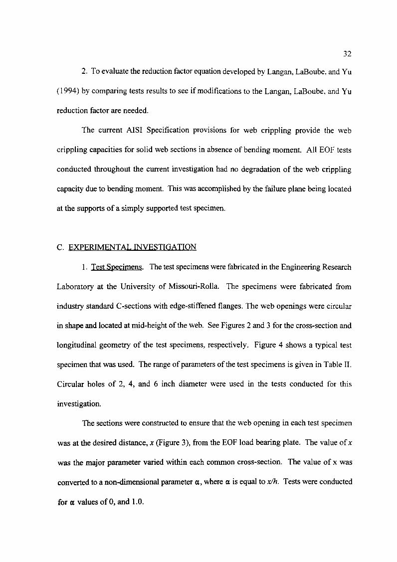
1. Test Specimens. The test specimens were fabricated in the Engineering Research
Laboratory at the University of Missouri-Rolla. The specimens were fabricated from
industry standard C-sections with edge-stiffened flanges. The web openings were circular
in shape and located at mid-height ofthe web. See Figures 2 and 3 for the cross-section and
longitudinal geometry of the test specimens, respectively. Figure 4 shows a typical test
specimen that was used. The range of parameters of the test specimens is given in Table II.
Circular holes of 2, 4, and 6 inch diameter were used in the tests conducted for this
investigation.
The sections were constructed to ensure that the web opening in each test specimen
was at the desired distance, x (Figure 3), from the EOF load bearing plate. The value of x
was the major parameter varied within each common cross-section. The value of x was
converted to a non-dimensional parameter ex, where ex is equal to x/h. Tests were conducted
for ex values of 0, and 1.0.

(a)
(b)
Figure 4 Typical EOF Te~t Specimens, (a) side view, (b) plan view.
33

34
The length of the EOF bearing reaction plate, N (Figure 3), was kept at a constant
value of 1 inch. The value of N and the value of x determine the longitudinal distance
between the end of the section and the web opening.
The length ofeach test specimen was determined in order to satisfy the requirement
for one-flange loading; greater than or equal to 1.5h clear distance between the end plate and
the mid-span loading plate. End-one-flange loading criteria is given in Figure 1. The greater
value of the following two equations was used to determine the minimum length of each test
specimen:
and,
L . =2(1.5h+N)+3, inchesmID
L . =(2(x+b))+2N+3, inchesmID
(17)
(18)
The value ofx is the clear distance between the edge of bearing to the edge of the hole. The
parameter b is the diameter of the hole in the web.
2. Test Setup. In order to be able to conduct the tests, two C-sections of the same
minimum length were spaced approximately 6 Y2 inches apart, parallel in the longitudinal
direction, and interconnected with one inch aluminum angle, screwed to the top and bottom
flanges ofeach section. This was done in order to prevent lateral-torsional buckling of the
specimens. To prevent web crippling beneath the load point, a stiffener was connected
vertically at mid-span of each C-section with screws. These bearing stiffeners were also
used to transfer the applied load to the web so that the flange was not being loaded. This
method was used in previous web crippling studies by Langan, LaBoube, and Yu (1994).

35
Using a Tinius-Olsen machine, Figure 5, a concentrated load was applied at mid-span
to a three inch bearing plate in contact with the web stiffeners. The reactions creating the
EOF loading were introduced to the specimen by bearing plates flush with the ends of the
specimen, Figure 3. Therefore, the value of d\, Figure I, was equal to zero for all tests.
3. Test Procedure. The test specimens were loaded under a steady and gradual load
until failure. Load was applied to a 25 pound plate placed on the top of the web stiffners at
mid-span of the specimen. Failure occurred when the test specimen could no longer carry
any additional load. At least two tests were conducted for each test specimen. Tests without
holes in the web were conducted on each C-section specimen to serve as the control
specimens. This testing procedure was used in previous studies by Langan, LaBoube, and
Yu (1994).
Figure 5 Tinius Olsen Testing Machine

36
D. TEST RESULTS
1. General. Fifty-Five unreinforced single web EOF tests were conducted during this
investigation. Ofthese, 52 failed in web crippling and the other three failed due to an over
all stability.
The test failure load per web, (P,)test' for specimens failing due to web crippling was
recorded and is shown for each specimen in Table III. It is assumed that the value of (P,)test
is equal to 1/4 of the mid-span applied load. Therefore, each of the tests specimen's four
contact points with the EOF loading plates is assumed to equally support the applied load.
2. Typical Failures. Typical web crippling failures of the unreinforced EOF test
specimens are shown in Figures 6, 7, 8, and 9. Figure 6 shows a solid web specimen, with
a typical EOF web crippling failure. Figures 7 and 8 show a typical web crippling failure for
a specimen with a web opening that has an ex value equal to one. Figure 9 shows a specimen
with the failure load still applied.
3. Web Cripplin~ Deformation at Failure. At failure, the speCImens were
permanently deformed and would be considered unserviceable under most applications. This
is an important consideration in the selection of the ASD Specification (1986) factor of
safety and the LRFD Specification (1991a) resistance factor. Due to the complexity of
determining the deformation due to web crippling, the AISI Specifications do not have
serviceability criteria for web crippling. This helps explain the conservative factors of safety,
1.85, used by AISI ASD provisions and the resistance factor, 0.75, used by AISI LRFD
provisions.
The web crippling deformation for tests without web openings were very localized
at the bearing reaction plate, Figure 6. As the a/h ratio increased the web crippling occurred

(a)
(b)
Figure 6 Typical EOF Solid Web Specimen Failures: (a) end view, (b) side view
37

(a)
(b)
Figure 7 Typical EOF Web Crippling Failure with High a/h ratio and (X equal to 1:(a) end view (b) side vie_w
38
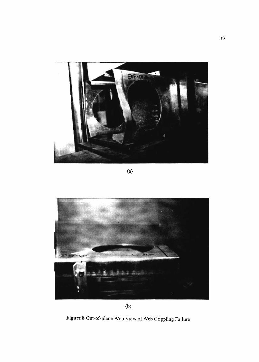
(a)
(b)
Figure 8 Out-of-plane Web View of Web Crippling Failure
39

40
Figure 9 Failure Load Applied to Specimen
further away from the bearing reaction plate and moved up into the edge of the web
opening, Figure 7. For test specimens with a values of 1.0 the web crippling was located
locally at the bearing reaction plate as in the solid web sections.
E. EVALUATION OF TEST RESULTS
1. General. For the current UMR study on EOF loading condition, the web crippling
capacity was considered without degradation of the web strength due to bending. Therefore,
the percent-of-solid-web-strength, PSW, could be recorded directly without any adjustments
for significant bending.
The primary measure of the effect of circular web openings on EOF web crippling
capacity is the failure load, (P,)'es/, of the test specimens (Table III). The parameters
associated with the circular web openings were used to measure the effect of the web

41
crippling capacity. A previous study by Langan. LaBoube, and Yu (1994) and the
parameters «, a1h, and hit were considered in detennining the effects of EOF web crippling
capacity.
2. Effect of « on Web Cripplin~ Capacity. In the process of evaluating the test
results of both the current UMR study and the Langan, LaBoube, and Yu (1994)
investigation, a notable trend was observed within the test results. As the value of «
increased from 0 to 1.5 (combined studies), the web crippling capacity, PSW, increased.
Data points from the current UMR study are graphically illustrated in Figure 10 to show the
increasing PSWassociated with the increasing «values. The range of « values for this study
were from 0.0 to 1.0.
3. Effect of a1h on Web Cripplin~ Capacity. Another notable trend that was
determined to effect the web crippling capacity was the parameter a1h. It was noted that
as a1h increased the PSW distinctively decreased. Therefore, it was concluded that a1h is
inversely proportional to the PSW. Figure 11 shows the inverse relationship of
decreasing PSW corresponding to increasing a1h ratio's. The range of a1h values for this
investigation is from 0.266 to 0.812.
F. EVALUATION OF LANGAN. LABOUBE. AND)lJ REDUCTION FACTOR
EQUATION
1. General. In the evaluation of the current test results, it was determined that the
same parameters, « and a1h, incorporated in the Langan, LaBoube, and Yu (1994)
reduction factor equation (Eq. 7), were the controlling parameters effecting the EOF web
crippling capacity. Therefore, the Langan, LaBoube, and Yu reduction factor equation

42
1.4 .4~ i
i1.2 ...--.----~-.-- ..---.-.-+-.-.---.--.-.-~.-----.~,-----+-----
1.20.80.6a1pha(xIh)
0.40.2
! i !~ 1 ,;---·--I----j---- -t----t--T·----·--
4 ! i ! i •0.8 , ....·--·-r-·----·-·-·-·-·----r ·------·---------i r :
~ i io6 ~--__i~----__J_-.----... i .__..-.....__...-. ! :----~-
i ii i
! i0.4 +--t---+--+---+--t---+--+--+-~f---+--+-~
o
I • Thickness 0.033 in. • Thickness 0.056 ilL IFigure 10 Graphic Illustration of (X (x/h) vs. PSW for Current UMR Study
1.2 .---.,.------:----,--.,...---~---,---..,• i
!: j
''Z t·------ ! ...
• ! • i ! fIlA
0.8 +-----ji~---f----+!--.--....---~-.-.--.----------~ i : ..
~ 0.6 I----·--·-+----t·-·-·---'---+,----r-·-·-- \ "_._on
::: +~--·---·-·~:~~~~·-I-=C=r-----.~- ---"~~--.-~~
0.90.80.70.5 0.6alb Ratio
0.4
ij
0+--+----1'----+---+-~+-+--~-+--+---+---+---J
0.2 0.3
I • Thickness 0.033 in. ... Thickness 0.056 iD·1
Figure 11 Graphic Illustration ofa/h vs. PSW for Current UMR Study

Table III Unreinfofced EOF Test Results
Specimen L N (X (P) PSW Limit State Reduction Factor
Number (in.) (in.) (lbs.) LanganRF Current RF
EOF-CS-16-0-0-1 27.16 1 ----- 756.25 1.04 WEB CRIPPLING 1.08 1.01
EOF-CS-16-0-0-2 27.16 1 ----- 725.00 1.00 WEB CRIPPLING 1.08 1.01
EOF-CS·16-0-0-3 27.16 1 ----- 725.00 1.00 WEB CRIPPLING 1.08 1.01
EOF-C8-16-0-0-4 27.16 1 ----- 706.25 0.97 WEB CRIPPLINU 1.08 1.01
EOF-C8-16-0-2-1 27.16 1 0 787.50 1.08 WEB CRIPPLING 0.91 0.92
EOF-CS-16-0-2-2 27.16 1 0 831.25 1.14 WEB CRIPPLING 0.91 0.92
EOF-C8-16-0-2-3 27.16 1 0 750.00 1.03 WEB CRIPPLING 0.91 0.92
I~( >1"-<..:8-16-0-2-4 27.16 I () 725.00 1.00 WEB CRIPPLING 0.91 0.92
EOF-C8-16-1-2-1 27.16 I I 725.00 1.00 WEB CRIPPLING 1.00 1.01
EOF-C8-16-0-4-1 27.16 1 0 668.75 0.92 WEB CRIPPLING 0.74 0.84
EOF-C8-16-0-4-2 27.16 1 0 743.75 1.00 WEB CRIPPLING 0.74 0.84
+:w

Table III Unreinforced EOF Test Results (cont'd)
Specimen L N (X (P) PSW Limit State Reduction Factor
Number (in.) (in.) (lbs.) LanganRF Current RF
EOF-C8-16-0-4-3 27.16 1 0 675.00 0.93 WEB CRIPPLING 0.74 0.84,
EOF-C8-16-1-4-1 27.78 I I 781.25 1.07 WEB CRIPPLING 0.86 0.92
EOF-C8-16-1-4-2 27.78 I 1 800.00 1.10 WEB CRIPPLING 0.86 0.92
EOF-C8-16-0-6-1 27.16 1 0 487.50 0.67 WEn CRIPPLING 0.57 0.75
EOF-C8-16-0-6-2 27.16 I 0 493.75 0.68 WEB CRIPPLING 0.57 0.75
EOF-C8-16-1-6-1 31.78 I 1 668.75 0.92 WEB CRIPPLING 0.69 0.83
EOF-C8-16-1-6-2 31.78 1 I 725.00 1.00 WEB CRIPPLING 0.69 0.83
EOF-C8-20-0-0-1 27.53 1 ----- 306.25 1.04 WEB CRIPPLING 1.00 1.01
EOF-C8-20-0-0-2 27.53 I ----- 281.25 0.96 WEB CRIPPLING 1.00 1.01
EOF-C8-20-0-2-1 27.53 1 0 262.50 0.89 WEB CRIPPLING 0.91 0.93
~~

Table III Unreinforced EOF Test Results (cont'd)
Specimen L N a (P) PSW Limit State Reduction Factor
Number (in.) (in.) (lbs.) Langan RF Current RF
EOF-C8-20-0-2-2 27.53 1 0 262.50 0.89 WEB CRIPPLING 0.91 0.93
EOF-C8-20- I-2-1 27.53 1 1 275.00 0.94 WEB CRIPPLING 1.00 1.01
EOF-C8-20-1-2-2 27.53 1 1 262.50 0.89 WEB CRIPPLING 1.00 1.01
EOF-C8-20-0-4-1 27.53 1 0 268.75 0.91 WEB CRIPPLING 0.74 0.84
EOF-C8-20-0-4-2 27.53 1 0 268.75 0.91 WEB CRIPPLING 0.74 0.84
EOF-C8-20-1-4-1 28.02 1 1 306.25 1.04 WEB CRIPPLING 0.86 0.92
EOF-C8-20-1-4-2 28.02 1 1 293.75 1.00 WEB CRIPPLING 0.86 0.92
EOF-C8-20-0-6-1 27.53 1 0 181.25 0.62 WEB CRIPPLING 0.58 0.75
EOF-C8-20-0-6-2 27.53 1 0 187.50 0.64 WEB CRIPPLING 0.58 0.75
EOF-C8-20-1-6-1 32.02 1 1 250.00 0.85 WEB CRIPPLING 0.70 0.84
EOF-C8-20-1-6-2 32.02 1 1 243.75 0.83 WEB CRIPPLING 0.70 0.84
...VI

Table III Unreinforced EOF Test Results (cont'd)
Specimen L N ex (P) PSW Limit State Reduction Factor
Number (in.) (in.) (lbs.) LanganRF Current RF
EOF-C6-16-0-0-1 21.59 I ----- 937.50 1.08 WEB CRIPPLING 1.08 1.01
EOF-C6-16-0-0-2 21.59 I ----- 868.75 1.00 WEB CRIPPLING 1.08 1.01
EOF-C6-16-0-2-1 21.59 I 0 868.75 1.00 WEB CRIPPLING 0.85 0.89
EOF-C6-16-0-2-2 21.59 I 0 843.75 0.97 WEB CRIPPLING 0.85 0.89
EOF-C6-16-1-2-1 21.59 I 1 837.50 0.96 WEB CRIPPLING 0.97 0.98
EOF-C6-16-1-2-2 21.59 1 1 831.25 0.96 WEB CRIPPLING 0.97 0.98
EOF-C6-16-0-4-1 21.59 I 0 668.75 0.77 WEB CRIPPLING 0.62 0.78
EOF-C6-16-0-4-2 21.59 I 0 693.75 0.80 WEB CRIPPLING 0.62 0.78
EOF-C6-16-1-4-1 24.06 I I 806.25 0.93 WEB CRIPPLING 0.74 0.86
EOF-C6-16-1-4-2 24.06 I I 818.75 0.94 WEB CRIPPLING 0.74 0.86
+:0'1

Table III Unreinforced EOF Test Results (cont'd)
Specimen L N a (P) PSW Limit State Reduction Factor
Number (in.) (in.) (lbs.) Langan RF Current RF
EOF-C6-20-0-0-1 21.66 1 ----- 300.00 1.00 WEB CRIPPLING 1.00 1.01
EOF·C6-20-0-0-3 21.66 1 ----- 300.00 1.00 WEB CRIPPLING 1.00 1.01
EOF-C6-20-0-2-1 21.66 1 0 406.25 1.35 WEB CRIPPLING 0.85 0.89
EOF-C6-20-0-2-2 21.66 I 0 275.00 0.92 WEB CRIPPLING 0.85 0.89
EOF-C6-20-1-2-1 21.66 1 1 300.00 1.00 WEB CRIPPLING 0.97 0.98
EOF-C6-20-1-2-2 21.66 1 1 281.25 0.94 WEB CRIPPLING 0.97 0.98
EOF-C6-20-0-4-1 21.66 I 0 250.00 0.83 WEB CRIPPLING 0.63 0.78
EOF-C6-20-0-4-3 21.66 1 0 237.50 0.79 WEB CRIPPLING 0.63 0.78
EOF-C6-20-1-4-1 24.10 1 1 293.75 0.98 WEB CRIPPLING 0.75 0.86
EOF-C6-20-1-4-2 24.10 1 1 287.50 0.96 WEB CRIPPLING 0.75 0.86
~-l

48
(Eq. 7) was compared to the current findings. However, this comparison discovered that
Equation 7 was conservative at high a/h ratio's.
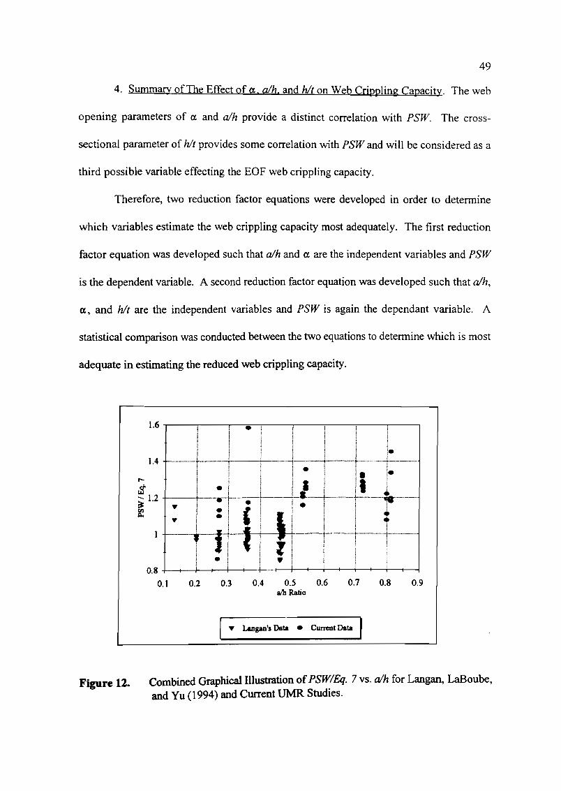
2. Effect of Langan. LaBoube. and Yu RF Equation on High a/h Values. Figure 12
graphically illustrates PSW/Eq.7 vs. a/h for the combined test results of the combined
Langan, LaBoube, and Yu (1994) study and the current UMR study. It can be noted that at
a/h values greater than 0.5, the corresponding values of PSW/Eq. 7 become considerably
greater than 1.0. Therefore, as a result of this finding the Langan, LaBoube, and Yu
reduction factor equation (Eq. 7) is considered to be conservative for a/h ratio's greater than
0.5.
Furthermore, Figure 12 illustrates that at a/h ratio's greater than 0.5, there were no
tests conducted during the Langan (1994) investigation. Therefore, the current UMR study
test results are beyond the range of the a/h values for the Langan (1994) investigation.
Hence, a new reduction factor equation was developed.
3. Effect of Langan. LaBoube. and Yu RF Equation on hit Ratio. Further
consideration was given to the effects of hit on the web crippling capacity and the validity
of the Langan, LaBoube, and Yu (1994) reduction factor equation (Eq. 7). Figure 13
graphically illustrates the relationship of PSW/Eq. 7 vs. hit ratio. The current findings show
that the Langan, LaBoube, and Yu (1994) reduction factor equation (Eq. 7) should consider
the effects of the cross-sectional parameter of hit. Figure 13 illustrates that for hit values
greater than 100, the corresponding PSW/Eq. 7 values are considerably greater than 1.0.
Therefore, the effect of hit should be considered in a new reduction factor equation.
49
4. Summary ofThe Effect of (x, a/h, and hit on Web Crippling Capacity. The web
opening parameters of (X and a/h provide a distinct correlation with PSW. The cross-
sectional parameter of hit provides some correlation with PSW and will be considered as a
third possible variable effecting the EOF web crippling capacity.
Therefore, two reduction factor equations were developed in order to determine
which variables estimate the web crippling capacity most adequately. The first reduction
factor equation was developed such that a/h and (X are the independent variables and PSW
is the dependent variable. A second reduction factor equation was developed such that a/h,
(x, and hit are the independent variables and PSW is again the dependant variable. A
statistical comparison was conducted between the two equations to determine which is most
adequate in estimating the reduced web crippling capacity.
1.6 ,..----..--.,.---:;;;;.,...--,:---.,..-------,,.----,----,.------,i
! ! i·1.4 ·-·-·-··-·····-f----·-·----t---·+---·-··-l---t--..··-+-·--·f-·_.__ .
i! i· i !. i.; • j ! jill j! I ! ---la. L.
: 1--;-1 rr11--· I ----I--r---'-'---'-.--·--j-t--t-iJ+-·---1--·_···········j·_·_·_·..···t-·..·..·..···········
i fil l i ! ii i j iii ;
! • i j. j i i
0.90.80.70.4 0.5 0.6alb Ratio
0.30.2
0.8 +--+--+-I--4---+-+---t---+----1r--+---t---+-t---+--i
0.1
I... Langan's Data • CUlTCI1t Data I
Figure 12. Combined Graphical Illustration ofPSW/Eq. 7 vs. a/h for Langan, LaBoube,and Yu (1994) and Current UMR Studies.

50
1.8 ..------;----.,----,.---~---..,...---_,
240220200180bit
160140
0.8
!1.6 f--·..·..···· ·.._·..+- ·--f --·.·..·- : __.._.~.~---'~'-';"--.-----.-
: ! ~ ;• j ! 1 i
1.4 ~-_ ..-___+ l··----·-·-·--r-·-·-·-··--· _._.~--_._.
t-- • I !! i$ • iii , ~! .... ....~ 1.2 ~-';'-T---r--;-'" !-_. : i I
f-·-'--e.·! ·1,i-·-·'·----r!',..·..- •..-.-;-----t''"'''•..-----1! t: ! III -r--·----·-+----+-l-_.---j
iiiI! !0.6 +----ir---+--t--j----+--+--t---+--+--+----i,---j
120
I ... Langan's Data • Current Study I
Figure 13. Combined Graphical Illustration of PSW/Eq. 7 vs. hit for Langan(1994) andCurrent UMR Studies.
G. DEVELOPMENT OF REDUCTION FACTOR EQUATIONS
1. General. In order to incorporate a wider range of parameter values and to
consider the effect of hit on the EOF web crippling capacity, a new reduction factor
equation must be developed. The reduction factor equation developed by Langan,
LaBoube and Yu (1994), Equation 7, is valid for a/h values up to 0.5. For a/h values
greater than 0.5, reduction factor Equation 7 becomes overly conservative and therefore, a
new reduction factor equation needs to be developed.
Furthermore, the cross-sectional parameter, hit, was incorporated into the
reduction factor equation to estimate its contribution to the reduction in EOF web
crippling capacity. Therefore, a second reduction factor equation was developed to

51
consider the hit effect. This section will present and compare the reduction factor
equations developed during this investigation.
2. Reduction Factor Equation with a and a/h as Independent Variables. In order
to develop a reduction factor equation, a bivariate linear regression was performed on 120
test results comprised from the study by Langan, LaBoube, and Yu (1994) and the current
UMR study using the statistical analysis software "Kwikstat". The first equation was
developed with a and a/h as the independent variables and PSWas the dependent
variable. The resulting equation, with a maximum limit of 100 percent was found to be:
RF = 10 1.2 -32.45~+8.34a ~ 100% (18)h
or,
RFa
1.00 (19)= 1.01-0.325-+0.0834a <h
A PSW value of 100 percent signifies that no strength reduction is required.
It can be seen in Figure 14, PSW/Eq. 19 vs. a/h converges upon a value of unity.
For the data shown in Figure 14, the PSW/Eq. 19 ratio has a mean value of 0.995, and a
coefficient-of-variation equal to 0.102. A comparison between the statistical values for
Equation 19 and the statistical values using Equation 7 is given in Table IV. Table IV
shows that the statistical values for Equation 19 are less than those for Equation 7.
3. Reduction Factor Equation with a. a/h. and hit as Independent Variables. To
consider the effect of hit, a statistical analysis of the 120 test results was performed. The
resulting equation was developed with a, a/h, and hit as the independent variables and
PSWas the dependent variable. The resulting equation was found to be:

RF = 96.36-33.46~+9.31a+0.044~ < 100%h t -
or,
a hRF = 0.964 -0.335-+0.093 a +0.0004- < 1.00
h t -
A PSW value of 100 percent signifies no strength reduction is required.
52
(20)
(21)
It can be seen by Figure 15, that for PSW/Eq. 21 vs. a/h, the data points also fall
within an acceptable range of±20 percent. However, the statistical values produced
using Eq. 21 are less accurate than those using Eq. 19. Equation 21 results in a mean
value equal to 1.06, and a coefficient of variation of 0.1 01. Again, these values are less
than those given by the Langan, LaBoube, and Yu (1994) Equation 7, but are greater than
those given by Equation 19. A comparison of all three statistical analyses is given in
Table IV.
A comparison ofPSW/Eq. 19 vs. hit and PSW/Eq. 21 vs. hit is illustrated in
Figures 16 and 17, respectively. It can be seen that in Figures 16 and 17 the data points
fall within an acceptable range about unity of±20 percent. This illustrates that hJt does
not contribute significantly to the reduction of web crippling strength.

53
I;;
i
0.7 0.8 0.90.60.5alb
0.40.30.2
;
; ;;
1.4 e----t----r----...-.~-·-·--··--f·-·-·-·······-·-+--.......;--·-·-·1-·············i i
! !2: 1.2 . - i ;
-..-·_·_··t·--·---.-1'--+---"~·-·-:-·--·+--~---i'-··-··-
~ ~ : : j i Hi I) ]1 I-~ 1 +-----t.f---,-+-, ... : ....t-.-----.-- !-1-.---
0.8 ~-t-~ y I ~ -t----! I i
0.6 +---+---+---+---+--t-t--+---+--+--t---+--1-----.I--t--+-----i0.1
I ~ Langan's Data - Current Data I
Figure 14 Combined PSW/Eq. 19 vs. a/h of Langan, LaBoube, and Yu (1994) and CurrentUMR Studies.
Table IV Statistical Analysis and Comparison of Reduction Factor Equations
Langan Study Current Study Current Study(1994) (Eq. 20, Fig. 14) (Eq. 21, Fig. 15)
(Eq. 7, Fig. 12)
STATISTICS FOR PSWIRF vs. a!h
MEAN 1.02 0.995 1.06
STANDARD 0.132 0.102 0.107DEVIATION
COEFFICIENT 0.128 0.102 0.101OF VARIATION

54
0.2 0.3 0.4 0.5alb Ratio
I T Langan's Data • Current Data IFigure 15 Combined PSW/Eq. 21 vs. a/h ofLangan, LaBoube, and Yu (1994) and Current
UMR Studies.
240220200
;-+--_._.__....j
----i-----~_._._._ _ --
180hit
160140
i.--+----+--....-...-+-----11
•---"1 ' w: '" l
._--.-_. -!- I_..__+:---'''~--i- 1,' :
i • i'---1-+--'--+-'-" ·.-;If----~---+I-lII·._._._-. 'I!i -~-------+ ' I • -_._-_.....
i ! i ! I-----····--r---·i--·--· 1 i I --_.·-·-·-·····----~___i------·.+t...__----;i ----+-__.__.__.iii j
1.6 ...------.----..,,.----....,------,---,..-----,
J.5
1.4
1.3
~ 1.2$_1.1
~ I
0.9
0.8
0.7
0.6 +----l--1---+-----<I----+-+--t---+---+---f----+----l
120
I T Langan's Data • Current Data I
Figure 16 Combined PSW/Eq. 19 vs. hit ofLangan, LaBoube, and Yu (1994) and CurrentUMR Studies.

55
1.4 ~--~-----'---..,-----;------;----,
240220200180bit
160140
~tl-- r--:-l---:--1--C---~ i lii--1-- It--iii ! ! •r------T---l---r--r-r---··
j I I I
iii i0.6 +----t--+-~__t--+---+_---t--+--+----1~---+-__;
120
1.2
-N$-~ronQ..
0.8
I ... Langan's Data • CW'l'ellt Study IFigure 17 Combined PSW/Eq. 21 vs. hit ofLangan, LaBoube, and Yu (1994) and Current
UMR Studies.
H. DESIGN RECOMMENDATIONS
1. Reduction Factor Equation. The statistical comparison given in Table IV was
used as the measure of the effectiveness of the reduction factor equations developed in this
study and by Langan, LaBoube, and Yu (1994). Based on the statistical analysis, Equation
19 is recommended to be used as a reduction factor for the AISI Specification (1986) solid
web Equations 13 thru 16 for web crippling capacity.
2. Limitations of Reduction Factor Equation. The AISI ASD Specification (1986)
allowable web crippling capacity and the AlSI LRFD Specification (l991a) nominal web
crippling capacity for sections with web openings can be obtained by applying Equation 19

56
to Equations 13 thru 16. This can be accomplished by multiplying the values produced by
Equations 13 thru 16 by the reduction factor Equation 19.
The use of the reduction factor equation gives the web crippling capacity of sections
with web openings. Equation 19 is only applicable to specimens that meet the ranges of
applicability. The limiting factors that control the applicability of Equation 19 are as
follows: 1. the range of parameters for the test specimens given in Tables I-A through V-A
in the Appendix, 2. the imposed limits on the existing Specification provisions for web
crippling, 3. the industry imposed limits, and 4. engineering judgement.
The current AISI Specification (1986; 1991a) provisions provide the following limits
applied to Equations 13 through 16:
(1) The maximum hit value that is allowed is 200 even though tests in this
study were conducted on specimens with hit values as large as 224. No minimum hit value
is enforced.
(2) All Rlt values must be less than or equal to 6.0 for Equations 13 thru 16
to be valid. The range of Rlt values used for the current study was 3.336 to 5.256.
(3) All Nit values less than or equal to 210 are valid for use of Equation 19,
because this is the maximum limit for Equations 13 thru 16. The range of Nit values used
in the current study was 17.794 to 30.581 therefore, due to the significant difference between
the AISI maximum limit and the current study limit, the newly developed reduction factor
equation is only valid for a maximum Nit value of 31.
(4) All Nih values less than or equal to 3.5 are valid for the use of Equation
19 because this is the maximum limit for Equations 13 thru 16.,

57
(5) All evalues must be between the 45 to 90 degrees for Equation 19 to be
valid. This range is imposed for Equations 13 thru 16.
Industry standard imposes a maximum aIh limit of 0.5 for pre-punched holes.
However, the current study has broadened these limits to a/h values greater 0.5. Equation
19 is valid for aIh values from zero to 0.812.
The value ofa has a lower limit ofzero because any opening located above or below
an EOF load or reaction plate must provide web reinforcement. There is no maximum limit
for a because as a increases the maximum limit of 100 percent for the reduction factor will
be achieved and therefore, no reduction in web capacity is necessary.
The yield strength, FJf' range that was used in the current study was 47.0 to 56.8 ksi.
However, the Langan, LaBoube, and Yu (1994) data that was used in the current study used
values up to 93 ksi. Therefore, Equation 19 is valid for Fy values up to 93 ksi. For cross
sections with Fy greater than 66.5 ksi, a value of66.5 ksi must be used for Equations 13 thru
16 to be valid.
Even though the current study addressed only circular shaped web openings, there is
no requirement on the shape of web opening that can be used. Also, although this study
addressed only the end-one-flange loading condition, a companion UMR study investigated
the interior-one-flange loading condition (Deshmukh, 1996).

58
IV. CONCLUSIONS
A total of55 EOF web crippling strength tests were conducted on single web sections
with circular web openings. Analysis of the tests results provide two reduction factor
equations for the degradation ofweb capacity due to the web openings. Ofthe two reduction
factor equations developed (Eqs. 19 and 20) Equation 19 provided the best statistical
results. Equation 19 was also compared to the reduction factor equation (Eq. 7) developed
by Langan, LaBoube, and Yu (1994) which resulted in Equation 19 again providing the best
statistical analysis results. To determine the web crippling capacity for sections with web
openings, the reduction factor equation may be applied to the AISI Specification web
crippling equations (Eq. 13 thru 16). The design parameters must satisfy the limits of
applicability given in Section III.H.2.
The reduction factor equation (Eq. 19) is a function of the a. and a/h values of the
design situation in question. A range of a. and a/h has been identified in which no web
crippling capacity reduction is necessary. The incorporation of the reduction factor equation
can easily be implemented into standard practice to ensure that the reduced web crippling
capacity be taken into consideration. The application of the reduction factor equation
ensures that adequate strength and serviceability is achieved for sections with web openings.
Limit states such as shear, flexure, combined bending and web crippling, etc... should be
checked independently of the web crippling limit state.

59
V. FUTURE RESEARCH
Future studies benefit from not only the theoretical and analytical conclusions of this
research, but also from the logistic developments achieved throughout this investigation.
This investigation was specifically meant for the end-one-flange loading condition. Also,
only single web sections with the web hole located at mid-height of the section were
considered. Future studies may include:
1. Two-flange loading condition
2. Different shapes of single web sections other than C-sections
3. Multiple web sections
4. Closely spaced holes or holes of different shapes
5. Holes not located at mid-height of the web

Table I-A. Cross-Sectional Properties for End-One-Flange Test Specimens
Specimen D R t h B de a Fy hIt alb Rlt NIt(in) (in) (in) (in) (in) (in) (in) (in)
EOF-C8-16-0-0-1 7.938 0.219 0.056 7.388 1.625 0.438 solid 56.8 132.1 ---- 3.918 17.889
EOF-C8-16-0-0-2 7.938 0.219 0.056 7.388 1.625 0.438 solid 56.8 132.1 ---- 3.918 17.889
EOF-C8-16-0-0-3 7.938 0.219 0.056 7.388 1.625 0.438 solid 56.8 132.1 ---- 3.918 17.889
EOF-C8-16-0-0-4 7.938 0.219 0.056 7.388 1.625 0.438 solid 56.8 132.1 ---- 3.918 17.889
EOF-C8-16-0-2-1 7.938 0.219 0.056 7.388 1.625 0.438 2 56.8 132.1 0.271 3.918 17.889
EOF-C8-16-0-2-2 7.938 0.219 0.056 7.388 1.625 0.438 2 56.8 132.1 0.271 3.918 17.889
EOF-C8-16-0-2-3 7.938 0.219 0.056 7.388 1.625 0.438 2 56.8 132.1 0.271 3.918 17.889
EOF-C8-16-0-2-4 7.938 0.219 0.056 7.388 1.625 0.438 2 56.8 132.1 0.271 3.918 17.889
EOF-C8-16-1-2-1 7.938 0.219 0.056 7.388 1.625 0.438 2 56.8 132.1 0.271 3.918 17.889
EOF-C8-16-1-2-2 7.938 0.219 0.056 7.388 1.625 0.438 2 56.8 132.1 0.271 3.918 17.889
EOF-C8-16-0-4-1 7.938 0.219 0.056 7.388 1.625 0.438 4 56.8 132.1 0.541 3.918 17.889
EOF-C8-16-0-4-2 7.938 0.219 0.056 7.388 1.625 0.438 4 56.8 132.1 0.541 3.918 17.889
0\o

Table II-A. Cross-Sectional Properties for End-One-Flange Test Specimens
Specimen D R t h B d, a Fy hIt alb Rtt NIt(in) (in) (in) (in) (in) (in) (in) (in)
EOF-C8-16-0-4-3 7.938 0.219 0.056 7.388 1.625 0.438 4 56.8 132.1 0.541 3.918 17.889
EOF-C8-16-1-4-1 7.938 0.219 0.056 7.388 1.625 0.438 4 56.8 132.1 0.541 3.918 17.889
EOF-C8-16-1-4-2 7.938 0.219 0.056 7.388 1.625 0.438 4 56.8 132.1 0.541 3.918 17.889
EOF-C8-16-0-6-1 7.938 0.219 0.056 7.388 1.625 0.438 6 56.8 132.1 0.812 3.918 17.889
EOF-C8-16-0-6-2 7.938 0.219 0.056 7.388 1.625 0.438 6 56.8 132.1 0.812 3.918 17.889
EOF-C8-16-1-6-1 7.938 0.219 0.056 7.388 1.625 0.438 6 56.8 132.1 0.812 3.918 17.889
EOF-C8-16-1-6-2 7.938 0.219 0.056 7.388 1.625 0.438 6 56.8 132.1 0.812 3.918 17.889
EOF-C8-20-0-0-1 7.920 0.172 0.034 7.509 1.650 0.500 solid 47 224.1 ---- 5.134 29.851
EOF-C8-20-0-0-2 7.920 0.172 0.034 7.509 1.650 0.500 solid 47 224.1 ---- 5.134 29.851
EOF-C8-20-0-2-1 7.920 0.172 0.034 7.509 1.650 0.500 2 47 224.1 0.266 5.134 29.851
EOF-C8-20-0-2-2 7.920 0.172 0.034 7.509 1.650 0.500 2 47 224.1 0.266 5.134 29.851
EOF-C8-20-1-2-1 7.920 0.172 0.034 7.509 1.650 0.500 2 47 224.1 0.266 5.134 29.851
0\-

Table III-A. Cross-Sectional Properties for End-One-Flange Test Specimens
Specimen D R t b B de a Fy bIt alb Rlt NIt(in) (in) (in) (in) (in) (in) (in) (in)
EOF-C8-20-1-2-2 7.920 0.172 0.034 7.509 1.650 0.500 2 47 224.1 0.266 5.134 29.851
EOF-C8-20-0-4-1 7.920 0.172 0.034 7.509 1.650 0.500 4 47 224.1 0.533 5.134 29.851
EOF-C8-20-0-4-2 7.920 0.172 0.034 7.509 1.650 0.500 4 47 224.1 0.533 5.134 29.851
EOF-C8-20-1-4-1 7.920 0.172 0.034 7.509 1.650 0.500 4 47 224.1 0.533 5.134 29.851
EOF-C8-20-1-4-2 7.920 0.172 0.034 7.509 1.650 0.500 4 47 224.1 0.533 5.134 29.851
EOF-C8-20-0-6-1 7.920 0.172 0.034 7.509 1.650 0.500 6 47 224.1 0.799 5.134 29.851
EOF-C8-20-0-6-2 7.920 0.172 0.034 7.509 1.650 0.500 6 47 224.1 0.799 5.134 29.851
EOF-C8-20-1-6-1 7.920 0.172 0.034 7.509 1.650 0.500 6 47 224.1 0.799 5.134 29.851
EOF-C8-20-1-6-2 7.920 0.172 0.034 7.509 1.650 0.500 6 47 224.1 0.799 5.134 29.851
0\tv

Table IV-A. Cross-Sectional Properties for End-One-Flange Test Specimens
Specimen D R t h B df a Fy hIt alb Rlt NIt(in) (in) (in) (in) (in) (in) (in) (in)
EOF-C6-16-0-0-1 6.017 0.188 0.056 7.388 1.625 0.438 solid 56.8 98.39 ---- 3.336 17.794
EOF-C6-16-0-0-2 6.017 0.188 0.056 7.388 1.625 0.438 solid 56.8 98.39 ---- 3.336 17794
EOF-C6-16-0-2-1 6.017 0.188 0.056 7.388 1.625 0.438 2 56.8 98.39 0.362 3.336 17.794
EOF-C6-16-0-2-2 6.017 0.188 0.056 7.388 1.625 0.438 2 56.8 98.39 0.362 3.336 17.794
EOF-C6-16-1-2-1 6.017 0.188 0.056 7.388 1.625 0.438 2 56.8 98.39 0.362 3.336 17.794
EOF-C6-16-1-2-2 6.017 0.188 0.056 7.388 1.625 0.438 2 56.8 98.39 0.362 3.336 17.794
EOF-C6-16-0-4-1 6.017 0.188 0.056 7.388 1.625 0.438 4 56.8 98.39 0.362 3.336 17.794
EOF-C6-16-0-4-2 6.017 0.188 0.033 7.509 1.625 0.438 4 56.8 98.39 0.723 3.336 17.794
EOF-C6-16-1-4-1 6.017 0.188 0.033 7.509 1.625 0.438 4 56.8 98.39 0.723 3.336 17.794
EOF-C6-16-1-4-2 6.017 0.188 0.033 7.509 1.625 0.438 4 56.8 98.39 0.723 3.336 17.794
EOF-C6-20-0-0-1 5.961 0.172 0.033 T509 1.625 0.438 solid 50.5 169.8 ---- 5.256 30.581
EOF-C6-20-0-0-2 5.961 0.172 0.033 7.509 1.625 0.438 solid 50.5 169.8 ---- 5.256 30.581
0\w

Table V-A. Cross-Sectional Properties for End-One-Flange Test Specimens
Specimen D R t h B dr a Fy hit alh Rtt Nit(in) (in) (in) (in) (in) (in) (in) (in)
EOF-C6-20-0-0-3 5.961 0.172 0.033 5.552 1.625 0.438 solid 50.5 169.78 ---- 3.336 17.794
EOF-C6-20-0-2-1 5.961 0.172 0.033 5.552 1.625 0.438 2 50.5 169.78 0.360 3.336 17794
EOF-C6-20-0-2-2 5.961 0.172 0.033 5.552 1.625 0.438 2 50.5 169.78 0.360 3.336 17.794
EOF-C6-20-1-2-1 5.961 0.172 0.033 5.552 1.625 0.438 2 50.5 169.78 0.360 3.336 17.794
EOF-C6-20-1-2-2 5.961 0.172 0.033 5.552 1.625 0.438 2 50.5 169.78 0.360 3.336 17.794
EOF-C6-20-0-4-1 5.961 0.172 0.033 5.552 1.625 0.438 4 50.5 169.78 0.720 3.336 17.794
EOF-C6-20-0-4-2 5.961 0.172 0.033 5.552 1.625 0.438 4 50.5 169.78 0.720 3.336 17.794
EOF-C6-20-0-4-3 5.961 0.172 0.033 5.552 1.625 0.438 4 50.5 169.78 0.720 3.336 17.794
EOF-C6-20-1-4-1 5.961 0.172 0.033 5.552 1.625 0.438 4 50.5 169.78 0.720 3.336 17.794
EOF-C6-20-1-4-2 5.961 0.172 0.033 5.552 1.625 0.438 4 50.5 169.78 0.720 3.336 17.794
0\.j:>.

65
BmLIOGRAPHY
American Iron and Steel Institute, AISI, (1986), "Cold-Fonned Steel Design Manual:Specification for the Design ofCold-Fonned Steel Structural Members", August 19,1986, 1989 Adendum.
American Iron and Steel Institute, AISI, (1991a), "Load and Resistance Factor DesignSpecification fo Cold-Fonned Steel Design".
American Institute of Steel Construciton, AISC, (1990), "Steel Design Guide Series: Steeland Composite Beams with Web Openings".
Chan, P.W., and RG. Redwood, (1974), "Stresses in Beams with Circular Eccentric WebHoles", Journal of the Structural Division, Vol. 100, No. ST1, January 1974,Americna Society ofCivil Engineers.
Deshmukh, S. U., ''Behavior of Cold-Fonned Steel Web Elements with Web OpeningsSubjected to Web Crippling and a Combination ofBending and Web Crippling forInterior-Qne-Flange Loading," A thesis presented to the faculty of the University ofMissouri-Rolla in partial fulfillment ofthe requirements for the degree Master Sciencein Civil Engineering.
Hetrakul, N., and W.W. Yu, (1978), "Structural Behavior ofBeam Webs Subjected to WebCrippling and a Combination of Web Crippling and Bending", Final Report, CivilEngineering Study 78-4, University ofMissouri-Rolla, June 1978.
LaBoube, RA., (199Oa), "Design Guidelines for Web Elements with Web Openings", CivilEngineerning Department, University ofMissouri-Rolla, July 16, 1990.
Langan, I.E., RA LaBoube, and W.W. Yu, (1994), "Structural Behavior ofPerforated WebElements ofCold-Fonned Steel Flexural Members Subjected to web Crippling anda Combination of Web Crippling and Bending", PhD Dissertation, University ofMissouri-Rolla
Narayanan, R, and F.Y. Chow, (1984), "Ultimate Capacity of Uniaxially CompressedPerforated Plates", contained in publication titled. "Thin-Walled Structures" Vol.2No.3, Elsevier Science Publishers Ltd., Great Britain.
Redwood, R.G., H. Baranda, and M.J. Daly, (1978), "Tests of Thin-webbed Beams withUnreinforced Holes", Journal ofthe Structural Division, Vol. 104, No. ST3, March1978, American Society ofCivil Engineers.

66
Redwood, RG., and M. Uenoya, (1979), "Critical Loads for Webs with Holes", Journal ofthe Structural Division, Vo1l05, No, STI0, October 1979, American Society ofCivilEngineers.
Redwood, RG., and S.C. Shrivastava, (1980), "Design Recommendations for Steel Beamswith Web Holes", Canadian Journal of Civil Engineering, 7: No.4, pp. 642-650,December 1980.
Santaputra, C., and W.W. Yu, (1986), "Design ofAutomotive Structural Components UsingHigh Strength Sheet Steels (and) Web Crippling of Cold-Formed Steel Beams",Eighth Progress Report, Civil Engineering Study 86-1, University ofMissouri-Rolla,August 1986.
Santaputra, C., MB. Parks, and Yu, (1986), "Web-Crippling Strength ofCold-Formed SteelBeams", Journal of the Structural Division, Vol. 115, Bo. 10, October 1989,American Society ofCivil Engineers.
Sivakumaran, K.S., and K.M. Zielonka, (1989), "Web Crippling Strength of Thin-WalledSteel Members with Web Opeings", contained in publication titled, "Thin-WalledStructures", Elsevier Science Publishers Ltd., Great Britain.
Stiemer, S.F., and H.G.L. Prion, (1990), "Plastic Buckling Capacity ofSquare Shear Plateswith Circular Perforations", Annual Technical Session, Structural Stability researchCouncil, pp. 231-240.
Wmter, G., and RH.J. Pian, (1946), "Crushing Strength of Thin Steel Webs", Cornellbulletin 35, pt. 1, April 1946.
Yu, W.W., and C.S. Davis, (1973), "Cold-Formed Steel Members with PerforatedElements", Journal of the Structural Division, Vol 99, No. STI0, October 1973,American Society ofCivil Engineers.
Yu, W.W., (1991), Cold-Formed Steel Design: 2nd Ed., John Wiley and Sons, Inc.
Zetlin, L., (1955), "Elastic Instability of Flat Plates Subjected to Partial Edge Loads",Journal of the Structural Division, Vol. 81, September 1955, American Society ofCivil Engineers