structural calculations for cbkd series roof curbs
TRANSCRIPT

6593 Riverdale St.
San Diego, CA 92120
619-727-4800
Structural Calculations
for
CBKD Series Roof Curbs CBKD-161A (80-265-50)
2020 Florida Building Code requirements
Prepared for:
PROVENT
3847 Wabash Drive
Mira Loma, CA 91725
Date: May 19, 2021
Project Number: PV2101

/
STEEL ATTACHMENT WIND LOAD ROOF ANCHORAGE CONCRETE ATTACHMENT DETAIL
CENTER ON CURB FLANGE. SEE TABLE FOR CENTER ON CURB FLANGE. SEE TABLE FOR QUANTITY OF EVENLY SPACED 5/8" 0 A307 BOLTS Meets wind requirements for the QUANTITY OF EVENLY SPACED 3/4" 0 THRD'D
WELDED CURB
WELDED CURB\
A TT ACHED TO STEEL ANGLE BELOW DECK AT following codes: / ROD IN HIL Tl HIT-HY 200 EPOXY, 4" MIN. EACH CONNECTION POINT. FBC 2020 EMBED INTO CONCRETE.
/HEATHING WHERE OCCURS based on ASCE 7-
:,::;tf(1'.;ll; METAL DECK Wind:
190 mph exposure D category Ill or IV ""' /I / building, max BLDG height: 60 ft
- NORMAL WEIGHT CONC SLAB Kzt=1.00 max - fc=4000 PSI MIN - 6" MIN THICK CONC. - SPECIAL INSPECTION
r---_STEEL ANGLE BY OTHERS REQUIRED ( ESR-3187)
NO. OF ANCHORAGE BOLTS REQUIRED NO. OF ANCHORAGE BOLTS REQUIRED CURB KIT LONG SIDE* SHORT SIDE** UNIT
CURB KIT LONG SIDE* SHORT SIDE* UNIT 80-265-49 5 @ 8.63" o.c. [email protected]" o.c. LXS 80-265-49 80-265-50 80-265-13 80-265-45 80-265-46 80-265-29 80-265-19 80-265-18
CURB KIT 80-265-49 80-265-50 80-265-13 80-265-45 80-265-46 80-265-29 80-265-19 80-265-18
2 @ 34.5" o.c. 2@ 19" o.c. LXS 80-265-50 5 @ 8.63" o.c. 4 @ 9.67" o.c. 2 @ 34.5" o.c. 2@29" o.c. LXL 80-265-13 5 @ 15.25" o.c. 3@ 12.63" o.c. 2@61"o.c. 2 @ 25.25" o.c. SUNLINE 3-6 TON 80-265-45 5@ 14.59" o.c. 3@ 14.09" o.c.
2 @ 58.38" o.c. 2@ 28.19" o.c. PRESTIGE SMALL 80-265-46 5@ 18" o.c. 4@ 13.67" o.c. 2@72"o.c. 2@41" o.c. PRESTIGE LARGE 80-265-29 9 @ 8.67" o.c. 5 @ 9.88" o.c.
3 @ 34.69" o.c. 2 @ 39.5" o.c. PREDATOR 80-265-19 8@ 14.75" o.c. 6@ 14.4" o.c. 3 @ 51.63" o.c. 2@72" o.c. SUNLINE ULTRA 80-265-18 12@ 10.39" o.c. 8@ 10.29" o.c.
2@72" o.c. SUNLINE MAGNA
WOOD ATTACHMENT STEEL AND CONCRETE ANCHORS ARE 6"
IFROM EACH CORNER EVENLY SPACED WELDED CURB
\ CONCRETE OVER METAL DECK CENTER ON CURB FLANGE. SEE TABLE FOR
/ QUANTITY OF EVENLY SPACED 5/8" 0 WOOD LAG SCREWS
WELDED CURB\
(3.5" MIN. EMBED. INTO WOOD FRAMING) ,,...,-coNC OVER METAL DECK
r( 4•,a• MIN _.......-
(BY OTHERS) (SPECIFIC GRAVITY OF WOOD= 0.43 MIN)
NO. OF ANCHORAGE SCREWS REQUIRED LONG SIDE SHORT SIDE UNIT 6@ 7.7" o.c. 3 @ 11.5" o.c. LXS
5 @ 9.63" o.c. 5 @ 8.25" o.c. LXL 6@ 13" o.c. 3@ 14.63" o.c. SUNLINE 3-6 TON
6@ 12.48" o.c. 3@ 16.09" o.c. PRESTIGE SMALL 6@ 15.2" o.c. 4@ 15" o.c. PRESTIGE LARGE
[email protected]" o.c. 6 @8.7" o.c. PREDATOR 8@ 15.32" o.c. 6@ 15.2" o.c. SUN LINE ULTRA 14@ 9.1" o.c. 8@ 10.86" o.c. SUNLINE MAGNA
FOUR INCHES FROM EACH CORNER EVENLY SPACED.
-i\I[f 1: ,::if 1I1F STEEL ANGLE/FRAMING
BY OTHERS
NOTE: FOR CONC OVER METAL DECK OVER STEEL FRAMING USE STEEL ATTACHMENT
FORM NO:
LXL SUNLINE 3-6 TON PRESTIGE SMALL PRESTIGE LARGE
PREDATOR SUNLINE ULTRA SUNLINE MAGNA
1625 DIPLOMAT DRIVE SUBMITTED TO:
RRSROOFTOP CARROL TON, TX 75006 COMPANY: CB-25A
JOB NAME: PHONE (972) 247-7447 EQUIPMENT: DATE: REV: DRAWN BY: FAX (972) 243-0940 NOTES: 3/29/2021 2 ALL
SYSTEMS
6. 1
@ 57.13" o.c. 3
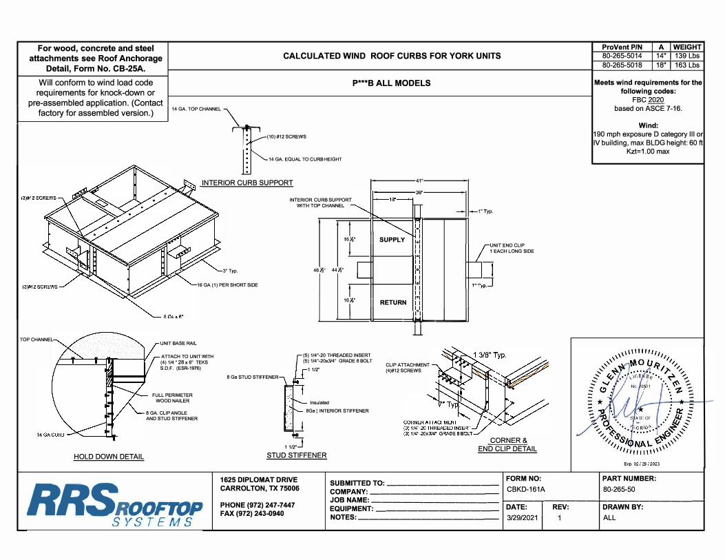
For wood, concrete and steel
attachments see Roof Anchorage
Detail, Form No. CB-25A.
CALCULATED WIND ROOF CURBS FOR YORK UNITS
Will conform to wind load code requirements for knock-down or
pre-assembled application. (Contact
I .
114 GA. TOP CHANNEL
'\
P ..... *B ALL MODELS
factory for assembled version.) \ (10) #12 SCREWS
TOP CHANNEL
HOLD DOWN DETAIL
14 GA. EQUAL TO CURB HEIGHT
INTERIOR CURB SUPPORT
3" Typ.
16 GA (1) PER SHORT SIDE
UNIT BASE RAIL
ATTACH TO UNIT WITH (4) 1/4 " 28 x 6" TEKS S.D.F. (ESR-1976)
FULL PERIMETER WOOD NAILER
8 GA. CLIP ANGLE AND STUD STIFFENER
8 Ga STUD STIFFENER
INTERIOR CURB SUPPORT WITH TOP CHANNEL
II SUPPLY
46½ 44½" [
Ll:[11 RETIJRN
=.LJI
(5) 1/4"-20 THREADED INSERT (5) 1/4 "-20x3/4" GRADE 8 BOLT
CLIP ATTACHMENT (4)#12 SCREWS 1 1/2"
Insulated 8Ga [ INTERIOR STIFFENER
·,]_j
1 1/2
STUD STIFFENER
UNIT END CLIP 1 EACH LONG SIDE
CORNER& END CLIP DETAIL
1625 DIPLOMAT DRIVE CARROL TON, TX 75006
SUBMITTED TO: __________ _ FORM NO:
COMPANY: ___________ _ CBKD-161A
Provent PIN A IWEIGHT 80-265-5014 14" I 139 Lbs 80-265-5018 18" I 163 Lbs
Meets wind requirements for the following codes:
FBC 2020 based on ASCE 7-16.
Wind: 190 mph exposure D category Ill or IV building, max BLDG height: 60 fl
Kzt=1.00 max
PART NUMBER:
80-265-50
RRrwt PHONE (972) 247-7447 FAX (972) 243-0940
JOB NAME: ____________ 1---------+-------------1
EQUIPMENT: ___________ _ NOTES: ____________ _
DATE: I REV:
3/29/2021
DRAWN BY:
ALL

6593 Riverdale St.
San Diego, CA 92120
(619)727-4800
Page ___ of ___
Client: ProVent PV2101 Previous: PV1807
Description: CBKD-161 80-265-50**
Unit: P***B ALL MODELS
Curb Information
Hcurb = 18 in (Height of curb)
Lcurb = 46.5 in (Length of curb)
wcurb = 41 in (Width of curb)
WGTcurb = 163 lbs (Weight of curb)
# Clips long side = 1 # Clips short side = 1
Unit Information
WGTunit = 420 lbs (Weight of Unit)
Wtmax = 141 lbs (Maximum corner weight)
Wtmin = 78 lbs (Minimum corner weight)
Hunit = 55 in (Height of unit above curb)
Hcm = 27.5 in (Height to center of mass)
Lunit = 51.25 in (Length of unit)
Wunit = 45.75 in (Width of unit)
Seismic Loading - 2020 FBC/2018 IBC
Ss = 0.15 (Worst Case for state of Florida)
Fa = 2.4 (Worst case Site class E from Table 11.4-1 ASCE 7-16)
Sms = 0.360 (Fa*Ss)
Sds = 0.240 (2/3*Sms)
Ip = 1.5 (Importance Factor Category III or IV Building)
Fpmax = 0.576 WGTunit (1.6*Sds*Ip)*WGTunit (Eq 13.3-2 ASCE 7-16)
FpmaxASD = 169 lbs (0.7*Fpmax) FpmaxASD = 235 lbs
(unit only) (unit and curb)
Wind Loading - 2020 FBC/2018 IBC *** Exposure Category D ***
Kz = 1.31 (For 60 ft roof height, Exposure D - Table 26.10-1 ACSE 7-16)
Kzt = 1.00 (Max. assumed topographic factor)
Kd = 0.85 (Directionality factor Table 26.6-1 ASCE 7-16)
Ke = 1.00 (Ground Elevation Factor Table 26.9-1 ASCE 7-16)
V = 190 (Wind velocity, mph for Occupancy Cat III-IV bldgs Exp. Cat C, Fig 26.5-1D - ASCE7-16)
GCr(horiz) = 1.9 (Refer Sect 29.4.1 ASCE 7-16)
GCr(vert) = 1.5 (Refer Sect 29.4.1 ASCE 7-16)
qz 102.9 psf = 0.00256*Kz*Kzt*Kd*Ke*V2 (Eq. 26.10-1 ASCE 7-10)Fh ASD trans = 3048 lbs = 0.6*qz*GCr*Lunit*(Hunit+Hcurb) (Eq. 29.4-2)
Fh ASD long = 2721 lbs = 0.6*qz*GCr*Wunit*(Hunit+Hcurb)
Fvert ASD = 1508 lbs = 0.6*qz*GCr*Lunit*Wunit (Eq. 29.4-3)
Curb Loading
Transverse:CompressionSEISMIC = 405 lbs =[FpmaxASD*Hcm+2*(1+0.14SDS)*Wtmax*wcurb]/wcurb
TensionSEISMIC = 167 lbs = CompSEISMIC-(0.6-0.14SDS)*WGTunit
CompressionWIND = 1460 lbs =[Fh transASD*Hcm+2*0.6*Wtmax*wcurb-FvertASD*wcurb/2]/wcurb
TensionWIND = 2716 lbs = CompWIND+Fvert-0.6*WGTunit
---> Negative values indicate opposite load.
Longitudinal:CompressionSEISMIC = 392 lbs =[FpmaxASD*Hcm+2*(1+0.14*SDS)*Wtmax*Lcurb]/Lcurb
TensionSEISMIC = 154 lbs = CompSEISMIC-(0.6-0.14SDS)*WGTunit
CompressionWIND = 1024 lbs =[Fh transASD*Hcm+2*0.6*Wtmax*Lcurb-FvertASD*Lcurb/2]/Lcurb
TensionWIND = 2280 lbs = CompWIND+Fvert-0.6*WGTunit
---> Negative values indicate opposite load.
Governing Reactions:Transverse: CompMAX = 1460 lbs ---> Along long edge of curb.
(on long edge) TensMAX = 2716 lbs ---> Along long edge of curb.
Longitudinal: CompMAX = 1024 lbs ---> Along short edge of curb.
(on short edge) TensMAX = 2280 lbs ---> Along short edge of curb.
---> Negative values indicate opposite load.
1 4
6593 Riverdale St.
San Diego, CA 92120
(619)727-4800
Page ___ of ___
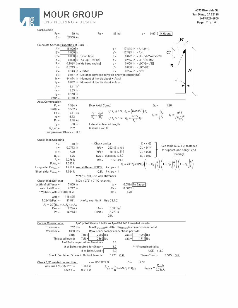
Curb Design
Fy = 50 ksi Fu = 65 ksi t = 0.0713 14 Gauge
E = 29500 ksi
Calculate Section Properties of Curb
A'= 18.000 in a = 17.644 in = A'-(2r+t)
B'= 1.000 in a'= 17.929 in = A'-t
C'= 0.000 in (0 if no lips) b = 0.822 in = B'-[r+t/2+α(r+t/2)]
α = 0.000 (0 - no Lip; 1 w/ lip) b'= 0.964 in = B'-(t/2+αt/2)R = 0.1069 (Inside bend radius) c = 0.000 in = α[C'-(r+t/2)]
t = 0.0713 in c'= 0.000 in = α(C'-t/2)
r'= 0.143 in = R+t/2 u = 0.224 in = πr/2
x = 0.047 in (Distance between centroid and web centerline)
Ix = 44.614 in (Moment of Inertia about X-Axis)
Iy = 0.039 in (Moment of Inertia about Y-Axis)
A = 1.41 in2
rx = 5.63 in
ry = 0.168 in
rmin = 0.168 in
Axial Compression
Pu = 1.524 k (Max Axial Comp) Ωc = 1.80
Pn/Ωc = 3.502 k
Fe = 5.11 ksi
λc = 3.13
Fn = 4.48 ksi
Ly = 50 in Lateral unbraced length
kyLy/ry = 239 (assume k=0.8)
Compression Check = O.K.
Check Web Crippling
h = 18 in -- Check limits: C = 4.00
t = 0.0713 in h/t = 252.45 ≤ 200 CR = 0.14
N = 7.00 N/t = 98.18 ≤ 210 CN = 0.35
Ωw = 1.75 N/h = 0.388889 ≤ 2.0 Ch = 0.02
Pn = 2.296 k R/t = 1.50 ≤ 9.0
Pn/Ωw = 1.312 k
Long side: PuTrans = 1.460 k web stiffener REQ'D # clips = 1
Short side: PuLong = 1.024 k O.K. # clips = 1
***h/t > 200; use web stiffeners
Check Web Stiffener 16Ga x 3/4" x 7" (C-channel)
width of stiffener = 7.000 in ts = 0.0566 16 Gauge
web of stiff. w = 6.717 in Rs = 0.0849 in
***Check w/ts ≤ 1.28√E/Fys Ωc = 1.70
w/ts = 118.675
1.28√(E/Fys) = 31.091 --> w/ts over limit Use C3.7.2
Pwc = 2.296 k Ae = 0.380 in2
Pn = 14.913 k Pn/Ω = 8.773 k
O.K.
Corner Connections 1/4" φ SAE Grade 8 bolts w/ 1/4-20-UNC Threaded inserts
Tcrnmax = 762 lbs Max(FpmaxASD/4 -OR- FhASDtrans/4 corner connections)
Vcrnmax = 1358 lbs (Max Ten/2 corner connections per side)
Bolt: Tall = 2480 lbs Vall = 1096 lbs
Threaded Insert: Tall = 2860 lbs Vall = 1714 lbs
# of Bolts required for Tension = 0.3
# of Bolts required for Shear = 1.2 ***If combined fails:
# of Bolts Used = 2.0 USE --> 3.0
Check Combined Stress in Bolts & Inserts: 0.773 O.K. StressComb = 0.515 O.K.
Check 1/8" welded connection <--- USE WELD Ω = 2.35
Assume L/t > 25: 25*t = 1.783 in
Lreq'd = 0.918 in
(See table C3.4.1-2, fastened
to support, one flange, end
loading)
=
λ =
λ ≤ 1.5; = 0.658
λ > 1.5; =0.877
λ
Ω=
!
Ω
Ω =
1
Ω0.75"#$ ≥ &'( #'()* =
&'(Ω
0.75"$
= 0.7 + + ! ≥ +
= -" sin (90) 1 − -56
"1 + -7
8
"1 − -9
ℎ
"
2 4
6593 Riverdale St.
San Diego, CA 92120
(619)727-4800
Page ___ of ___
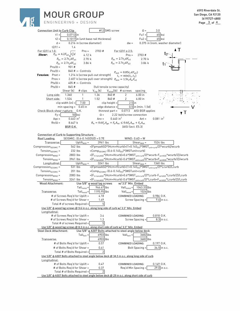
Connection Unit to Curb Clip #12 SMS screw Ω = 3.0
t1 = 0.0713 in Fu1 = 65 ksi
t2 = 0.1017 in (unit base rail thickness) Fu2 = 65 ksi
d = 0.216 in (screw diameter) dw = 0.375 in (nom. washer diameter)
t2/t1 = 1.4
For t2/t1 ≤ 1.0: Pns = 2703 # For t2/t1 ≥ 2.5:
4.12 k Pns = 2703 #
2.70 k 2.70 k
3.86 k 3.86 k
Pns/Ω = 901 #
Pss/Ω = 840 # <- Controls
Pnot = 1.214 k (screw pull-out strength)
Pnov = 2.607 k (screw pull-over strength)
Pts/Ω = 405 # <- Controls
Pts/Ω = 845 # (full tensile screw capacity)
Shear (k) # clips Vclip (k) Vallow(lb) # screws spacing
Long side: 1.360 1 1.36 840 # 2 6.00 in
Short side: 1.524 1 1.52 840 # 2 6.00 in
clip width (in) = 7.00 clip height = 2.5 in
min spacing = 0.65 in edge distance = 0.5 in (min. 1.5d)
Check Block shear rupture: O.K. thinnest part = 0.0713 AISI BSR applies
Fy = 50 ksi Ω = 2.22 bolt/screw connection
Agv = 0.463 in2 Anv = 0.440 in2 Ant = 0.081 in2
Rn/Ω = 8.647 k
BSR O.K. (AISI Sect. E5.3)
Connection of Curb to Supporting Structure
Roof Loading SEISMIC: (0.6-0.14SDS)D + 0.7E WIND: 0.6D + W
Transverse: UpliftMAX = 3961 lbs ShearMAX = 1524 lbs
CompressionSEISMIC = 562 lbs =[FpmaxASD*(Hcm+Hcurb)+(1+0.14SDS)*(WGTunit+curb/2)*wcurb]/wcurb
TensionSEISMIC = 232 lbs =CompSEISMIC-(0.6-0.14SDS)*(WGTunit+curb)
CompressionWIND = 2803 lbs =[Fh transASD*(Hcm+Hcurb)+0.6*(WGTunit+curb/2)*wcurb-FvertASD*wcurb/2]/wcurb
TensionWIND = 3961 lbs =[Fh transASD*(Hcm+Hcurb)-0.6*(WGTunit+curb/2)*wcurb+FvertASD*wcurb/2]/wcurb
Longitudinal: UpliftMAX = 3241 lbs ShearMAX = 1360 lbsCompressionSEISMIC = 531 lbs =[FpmaxASD*(Hcm+Hcurb)+(1+0.14SDS)*(WGTunit+curb/2)*Lcurb]/Lcurb
TensionSEISMIC = 201 lbs =CompSEISMIC-(0.6-0.14SDS)*(WGTunit+curb)
CompressionWIND = 2083 lbs =[Fh transASD*(Hcm+Hcurb)+0.6*(WGTunit+curb/2)*Lcurb-FvertASD*Lcurb/2]/Lcurb
TensionWIND = 3241 lbs =[Fh transASD*(Hcm+Hcurb)-0.6*(WGTunit+curb/2)*Lcurb+FvertASD*Lcurb/2]/Lcurb
Wood Attachment: Use 5/8" φ wood lag screws w/ 3.5" Min. Embed
Tallmetal = 946.67 lbs Vallmetal = 1043.33 lbs
Transverse: Tallwood = 1195.95 lbs Vallwood = 1024 lbs
# of Screws Req'd for Uplift = 4.18 COMBINED LOADING: 0.986 O.K.
# of Screws Req'd for Shear = 1.49 Screw Spacing = 9.6 in o.c.
Total # of screws Required = 5
Use 5/8" φ wood lag screws @ 9.6 in o.c. along long side of curb w/ 3.5" Min. Embed
Longitudinal:
# of Screws Req'd for Uplift = 3.4 COMBINED LOADING: 0.818 O.K.
# of Screws Req'd for Shear = 1.3 Screw Spacing = 8.3 in o.c.
Total # of screws Required = 5
Use 5/8" φ wood lag screws @ 8.3 in o.c. along short side of curb w/ 3.5" Min. Embed
Steel Deck Attachment: Use 5/8" φ A307 Bolts attached to steel angle below deck
Tallbolt = 6903 lbs Vallbolt = 3682 lbs
Transverse: 6903 lbs 3682 lbs
# of Bolts Req'd for Uplift = 0.57 COMBINED LOADING: 0.197 O.K.
# of Bolts Req'd for Shear = 0.41 Bolt Spacing = 34.5 in o.c.
Total # of Bolts Required = 2
Use 5/8" φ A307 Bolts attached to steel angle below deck @ 34.5 in o.c. along long side of curb
Longitudinal:
# of Bolts Req'd for Uplift = 0.47 COMBINED LOADING: 0.149 O.K.
# of Bolts Req'd for Shear = 0.37 Req'd Min Spacing = 29.0 in o.c.
Total # of Bolts Required = 2
Use 5/8" φ A307 Bolts attached to steel angle below deck @ 29 in o.c. along short side of curb
; = 4.2$ ">?
; = 2.7"@?$@
; = 2.7"?$
ABCDE:
GCHIJKH:
6 = 0.6 !LM + $!N ≤ 0.6$!M + $!N
; = 2.7"@?$@
; = 2.7"?$
ABCDE:
GCHIJKH:ON = 0.85"?$)
OM = 1.5"@?+$@
" = min ("@, ")
3 4

6593 Riverdale St.
San Diego, CA 92120
(619)727-4800
Page ___ of ___
For Concrete anchorage: SEISMIC (0.6-0.14SDS)D + 0.7Ωo E (Ωo = 2.5)
Concrete Attachment: 3/4" φ Hilti Hit-HY 200 adhesive anchors w/ 4" embed
TallLRFD = 1722 lbs VallLRFD = 2032 lbs
TallASD = TallLRFD/α = 920.9 lbs VallASD = VallLRFD/α = 1086.6 lbs
Transverse: UpliftMAX = 3961 lbs ShearMAX = 1524 lbs
CompressionSEISMIC = 953 lbs =[2.5*FpmaxASD*(Hcm+Hcurb)+(1+0.14SDS)*(WGTunit+curb/2)*wcurb]/wcurb
TensionSEISMIC = 623 lbs =CompSEISMIC-(0.6-0.14SDS)*(WGTunit+curb)
ShearSEISMIC = 294 lbs =2.5*FpmaxASD/2
Min Bolts Req'd Uplift = 4.30 spacing = 5.63 in o.c. Tapplied = 792.3 lbs
Min Bolts Req'd Shear = 2.00 spacing = 22.5 in o.c. Vapplied = 169.3 lbs
Try using 5 bolts
spaced at 8.63 in o.c.
Use 5 - 3/4" φ Hilti Hit-HY 200 adhesive anchors @ 8.6 in o.c. max. along long side of curb w/ 4" embed
Longitudinal: UpliftMAX = 3241 lbs ShearMAX = 1524 lbs
CompressionSEISMIC = 876 lbs =[2.5*FpmaxASD*(Hcm+Hcurb)+(1+0.14SDS)*(WGTunit+curb/2)*Lcurb]/Lcurb
TensionSEISMIC = 546 lbs =CompSEISMIC-(0.6-0.14SDS)*(WGTunit+curb)
ShearSEISMIC = 294 lbs =2.5*FpmaxASD/2
Min Bolts Req'd Uplift = 3.52 spacing = 5.666667 in o.c. Tapplied = 810.3 lbs
Min Bolts Req'd Shear = 2.00 spacing = 17 in o.c. Vapplied = 169.3 lbs
Try using 4 bolts
spaced at 9.67 in o.c.
Use 4 - 3/4" φ Hilti Hit-HY 200 adhesive anchors @ 9.7 in o.c. max. along short side of curb w/ 4" embed
CURB DESIGN SUMMARY: CBKD-161 80-265-50** Unit:
CURB RAIL THICKNESS: 0.0713 in 14 Gauge
UNIT CLIP THICKNESS: 0.0713 in 14 Gauge
# OF CLIPS (LONG SIDE) - 1 clips with 2 - #12 SMS screws each clip
WEB STIFFENER: 16Ga x 3/4" x 7" (C-channel) stiffener at each clip
# OF CLIPS (SHORT SIDE) - 1 clips with 2 - #12 SMS screws each clip
WEB STIFFENER: 16Ga x 3/4" x 7" (C-channel) stiffener at each clip
CORNER CONNECTION: Use 3 - 1/4" φ SAE Grade 8 bolts w/ 1/4-20-UNC Threaded inserts
LONG DIRECTION
SHORT DIRECTION
P***B ALL MODELS
COMBINED LOADING = = 1.04
COMBINED LOADING = = 1.02
CURB
ANCHORAGE
WOOD STEEL CONCRETE
5/8" φ lag screw w/ min. 3.5"
embed (SGmin=0.43)
5/8" φ A307 bolts to
steel angle below
3/4" φ thrd'd rod in Hilti HIT-HY
200 epoxy, min. 4" embed
5 @ 9.63 in o.c. 2 @ 34.5 in o.c. 5 @ 8.63 in o.c.
5 @ 8.25 in o.c. 2 @ 29 in o.c. 4 @ 9.67 in o.c.
∝= 1 + 0.2STS T + 2.5 =1.87
(T = 0.465, = 0.535)
VWXXYZ*
VWYYO+,[\]+
&WXYYZ*
&WYYO+,[\]≤ 1.2
VWXXYZ*
VWYYO+,[\]+
&WXYYZ*
&WYYO+,[\]≤ 1.2
4 4