structural design for wind loads: an overview of ... design for wind loads: an overview of...
TRANSCRIPT

Structural Design for Wind Loads: An Overview
of Engineering Considerations for Wood
BuildingsLori Koch, PE
Manager, Educational Outreach
American Wood Council

This presentation is protected by US and International
Copyright laws. Reproduction, distribution, display and use
of the presentation without written permission of AWC is
prohibited.
© American Wood Council 2016
Copyright Materials
2

3
“The Wood Products Council” is a Registered Provider with The American Institute of Architects Continuing Education Systems (AIA/CES), Provider #G516.
Credit(s) earned on completion of this course will be reported to AIA CES for AIA members. Certificates of Completion for both AIA members and non-AIA members are available upon request.
This course is registered with AIA CES for continuing professional education. As such, it does not include content that may be deemed or construed to be an approval or endorsement by the AIA of any material of construction or any method or manner ofhandling, using, distributing, or dealing in any material or product.________________________________Questions related to specific materials, methods, and services will be addressed at the conclusion of this presentation.
• This course is intended for structural engineers and building designers seeking an overview of design steps, considerations and detailing best practices related to the wind-resistive design and analysis of non-residential and multi-family wood buildings. Developed in response to the fact that engineering curricula does not typically include a wood design course, it provides an overview of relevant 2012 International Building Code (IBC) provisions and American Wood Council (AWC)-referenced standards, a discussion of common design errors, and guidance related to load path continuity, shear walls, diaphragms, and uplift restraint. Topics covered in detail include:
•
• 2012 IBC and AWC-referenced standards applicable to wood-frame wind-resisting systems
• Uplift-resistant design solutions, including combined shear and uplift
• Out-of-plane wall design for wind loads, including tall walls, gable end walls, and tall walls with large openings, as well as deflection criteria for a variety of wall finishes
• Design and stiffness assumptions for rigid, semi-rigid and flexible diaphragms
• Diaphragm deflection and design of components such as chords and collectors
• Shear wall design methods, including segmented, perforated and force transfer around openings
• Design of shear wall components, including holdowns and drag struts
• Multi-story wood-frame design example for high winds, including accommodation of accumulated forces and deflections as well as design and detailing for wood’s interface with concrete podiums and foundations
Course Description
4

Upon completion, participants will understand:1. Review applicable building codes and reference standards for the
design of non-residential and multi-family wood-frame wind-
resisting systems.
2. Discuss design and detailing of wood-frame diaphragms, including
flexibility, deflection, boundary fasteners, and chords and collectors.
3. Explore design steps for wood-frame shear walls, including panel
edge nailing, end posts and holdowns, drag struts, and transfer
mechanisms to lower floors and foundations.
4. Examine other wind-related design considerations, such as uplift
and out-of-plane wall forces, and discuss the design and detailing
effects of stacking multiple stories of wood-frame lateral force-
resisting systems.
Objectives
5

Outline
• ANSI• NDS• SDPWS• WFCM• Summary• More Info
6

ANSI Accreditation
• AWC –ANSI-accredited standards developer• Consensus Body• Wood Design Standards Committee
7

Outline
• ANSI• NDS• SDPWS• WFCM• Summary• More Info
8

NDS History
1944
1962
1968
1971
1973
1977
1982
1986
1991
1997
2001
2005
2012
2015
9

Governing Codes for Wood Design
2015 NDS referenced in 2015 IBC
10

2015 NDS – Primary Change
New Provisions to Address CLT
• Charging Language
• Design Values
• Design Equations
• Product Chapter
• Connection Design
• Fire Design
11

2015 NDS Chapter Reorganization
2012 NDS• 1-3 General
• 4-9 Products
• 10-13 Connections
• 14 Shear Walls & Diaphragms
• 15 Special Loading
• 16 Fire
2015 NDS• 1-3 General
• 4-10 Products +CLT
• 11-14 Connections
• Shear Walls & Diaphragms
• 15 Special Loading
• 16 Fire
12

NDS 2015 Chapters
1. General Requirements for Building Design
2. Design Values for Structural Members
3. Design Provisions and Equations
4. Sawn Lumber
5. Structural Glued Laminated Timber
6. Round Timber Poles and Piles
7. Prefabricated Wood I-Joists
8. Structural Composite Lumber
9. Wood Structural Panels
10. Cross-Laminated Timber
11. Mechanical Connections
12. Dowel-Type Fasteners
13. Split Ring and Shear Plate Connectors
14. Timber Rivets
15. Special Loading Conditions
16. Fire Design of Wood Members
13
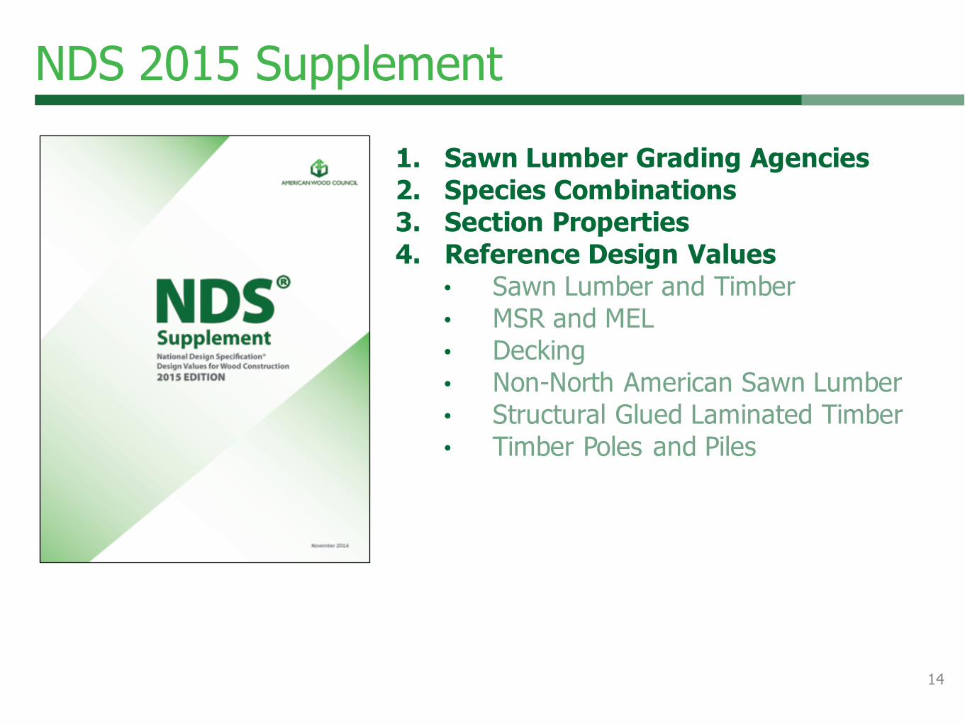
1. Sawn Lumber Grading Agencies2. Species Combinations3. Section Properties4. Reference Design Values
• Sawn Lumber and Timber
• MSR and MEL
• Decking
• Non-North American Sawn Lumber
• Structural Glued Laminated Timber
• Timber Poles and Piles
NDS 2015 Supplement
14

A. Construction and Design Practices
B. Load Duration (ASD Only)
C. Temperature Effects
D. Lateral Stability of Beams
E. Local Stresses in Fastener Groups
F. Design for Creep and Critical Deflection
Applications
G. Effective Column Length
H. Lateral Stability of Columns
I. Yield Limit Equations for Connections
J. Solution of Hankinson Equation
K. Typical Dimensions for Split Ring and Shear
Plate Connectors
L. Typical Dimensions for Standard Hex Bolts,
Hex Lag Screws, Wood Screws, Common,
Box, and Sinker Nails
M. Manufacturing Tolerances for Rivets and Steel
Side Plates for Timber Rivet Connections
N. Appendix for Load and Resistance Factor
Design (LRFD) – Mandatory
NDS 2015 Appendices
15

NDS – Chapter 1
16

Chapter 1 - Terminology
fb ≤ Fb'
Reference design values (Fb, Ft, Fv, Fc, Fc ,̂ E, Emin)
Adjusted design values (Fb', Ft', Fv', Fc', Fc '̂, E', Emin')
17

Chapter 1 – Design Loads
• Reference loads
• Minimum load standards
• ASCE 7 – 10
18

NDS – Chapter 2
19

Format Conversion Factor KF
RN = φ λ KF RASD
2015 NDS
RN = CDRASDASD
LRFD
RASD reference strengths
20

NDS – Chapter 3
21

Chapter 3 – CLT Design Equations
New
22

Chapter 3 – CLT Design Equations
NDS Commentary – guidance on CP
New 23

NDS – Chapter 4
24

Chapter 4 – Lumber
Design values• Visually graded lumber
• MSR / MEL
• Timber
• Decking
25

Chapter 4 – Lumber
Lumber adjustment factors
26

NDS – Chapter 5, 6, and 7
27
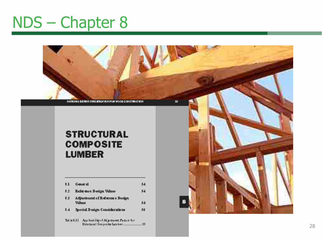
NDS – Chapter 8
28
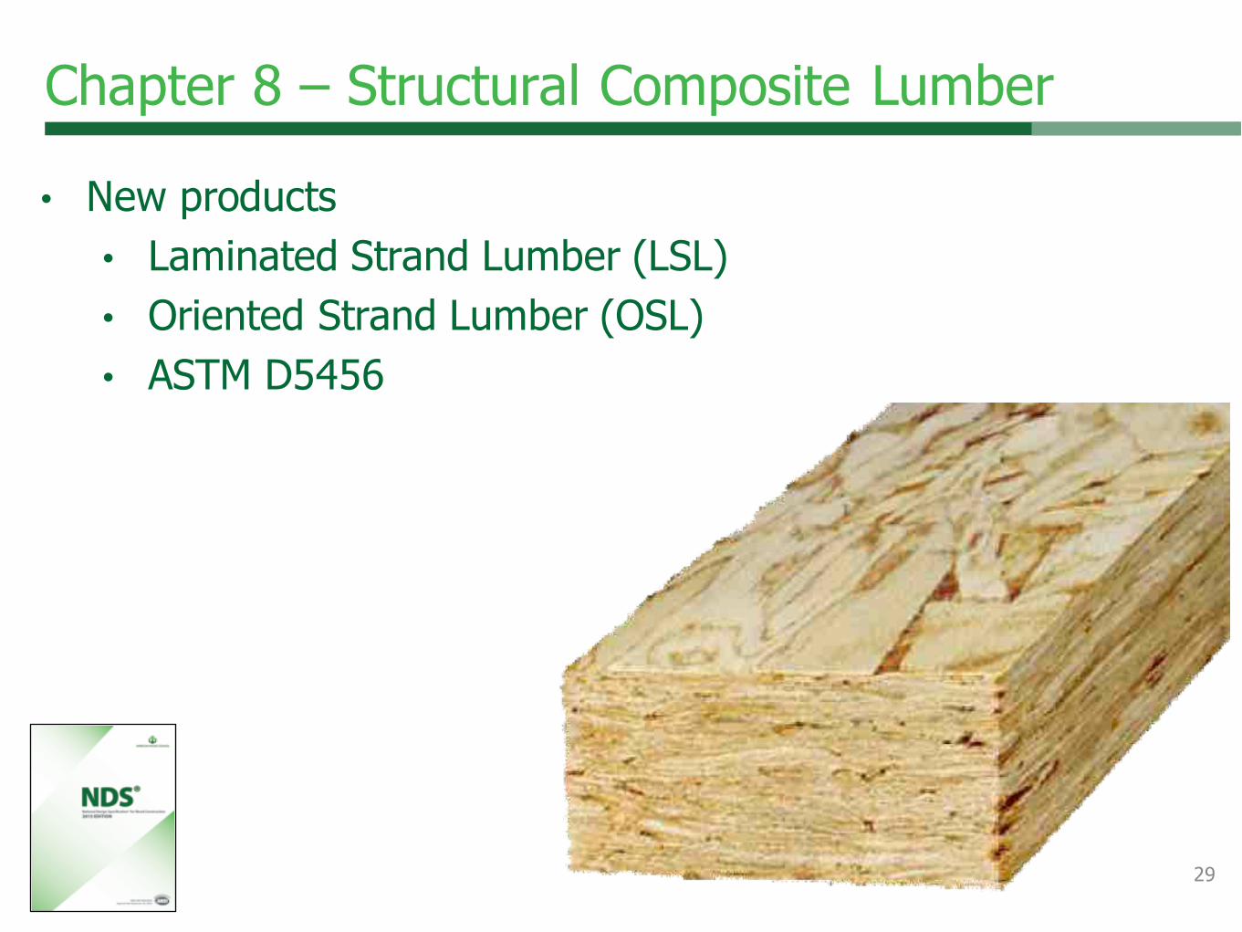
Chapter 8 – Structural Composite Lumber
• New products
• Laminated Strand Lumber (LSL)
• Oriented Strand Lumber (OSL)
• ASTM D5456
29

NDS – Chapter 9
30

Chapter 9 – Wood Structural Panels
Design values – obtain from an approved source• FbS
• FtA
• Fvtv
• Fs
• FcA
• EI
• EA
• Gvtv
• Fc^
31

Chapter 9 – Wood Structural Panels
Adjustment factors
32

NDS – Chapter 10
New
33

What is Cross Laminated Timber (CLT)?
Photos provided by FPInnovations

Chapter 10 – Cross-Laminated Timber
New
35
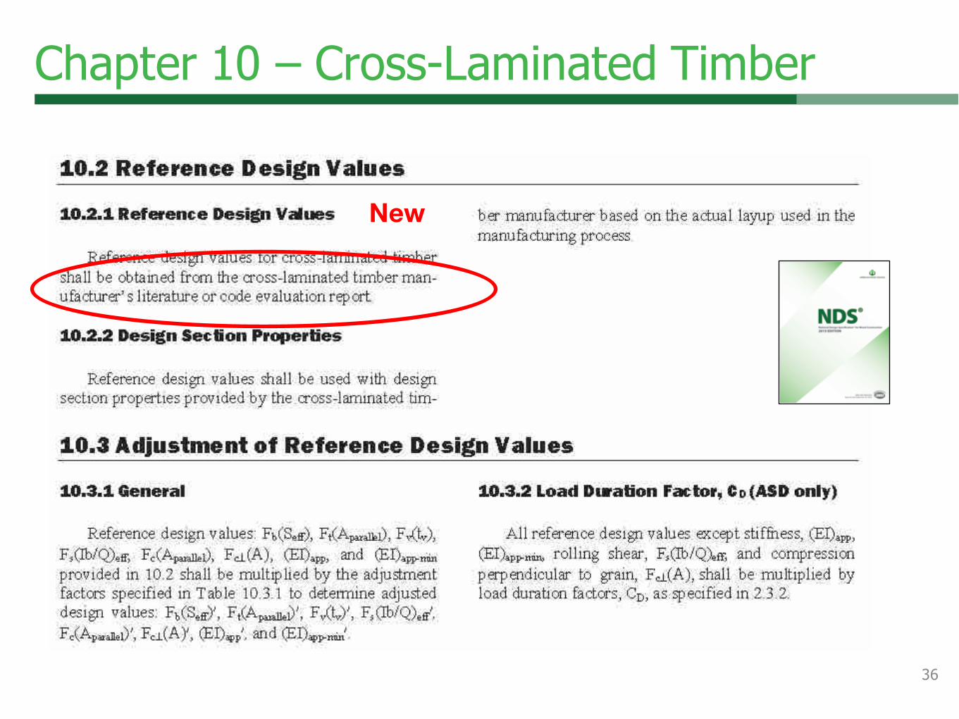
Chapter 10 – Cross-Laminated Timber
New
36

Chapter 10 – Cross-Laminated Timber
New
37

NDS – Chapter 11
Ch 10 Ch 1138
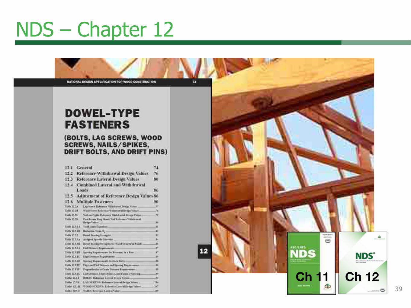
NDS – Chapter 12
Ch 11 Ch 1239

Chapter 12 – Dowel-type Fasteners
New
40

NDS – Chapter 13
Ch 12 Ch 1341

NDS – Chapter 14
Ch 13 Ch 1442

NDS – Chapter 15
43
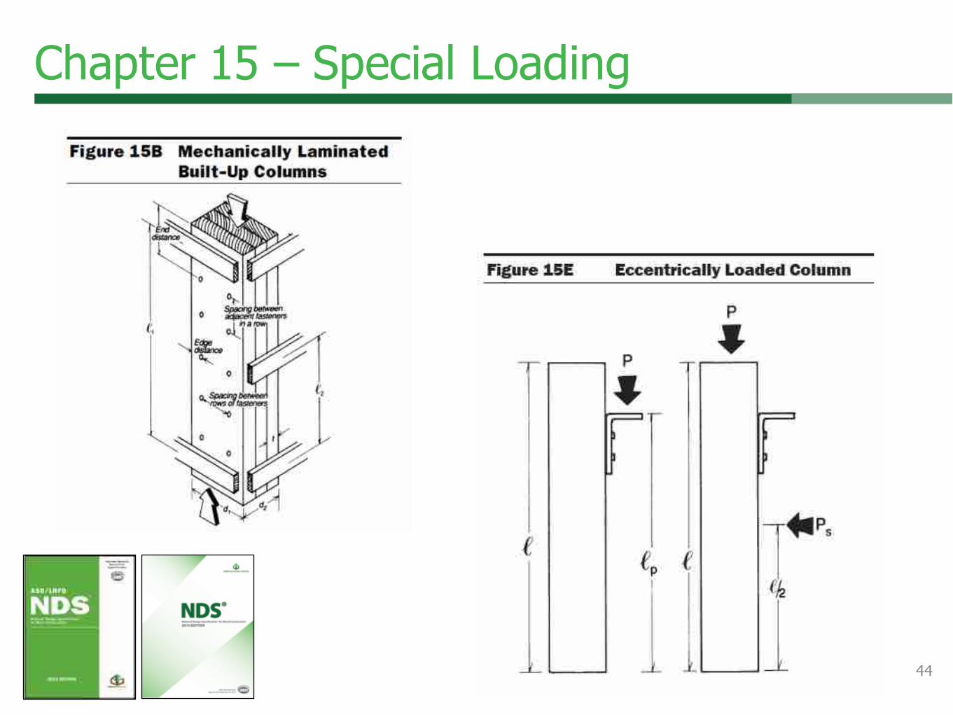
Chapter 15 – Special Loading
44

NDS – Chapter 16
45

…
Chapter 16 – Fire (ASD)
• Fire resistance up to two hours• Columns• Beams • Tension Members• ASD only
• Products• Lumber• Glulam• SCL• Decking• CLT - NEW
46

2015 NDS Supplement
• New Southern Pine Design Values
• ALSC approves design values
• June 1, 2013
• AWC compiles them
• NDS Supplement
• More information
• www.spib.org
• www.southernpine.com
47

Outline
• ANSI• NDS• SDPWS• WFCM• Summary• More Info
48

Code Acceptance of Standard
• 2015 IBC
• References 2015 SDPWS in Section
2305 for lateral design and
construction

• Chapter 1: Flowchart
• Chapter 2: General Design
Requirements
• Chapter 3: Members and
Connections
• Chapter 4: Lateral Force
Resisting Systems
General Overview
Outline

Chapter 2 – General Requirements
• Terminology
Definitions
• Flexible and Rigid Diaphragm removed
New
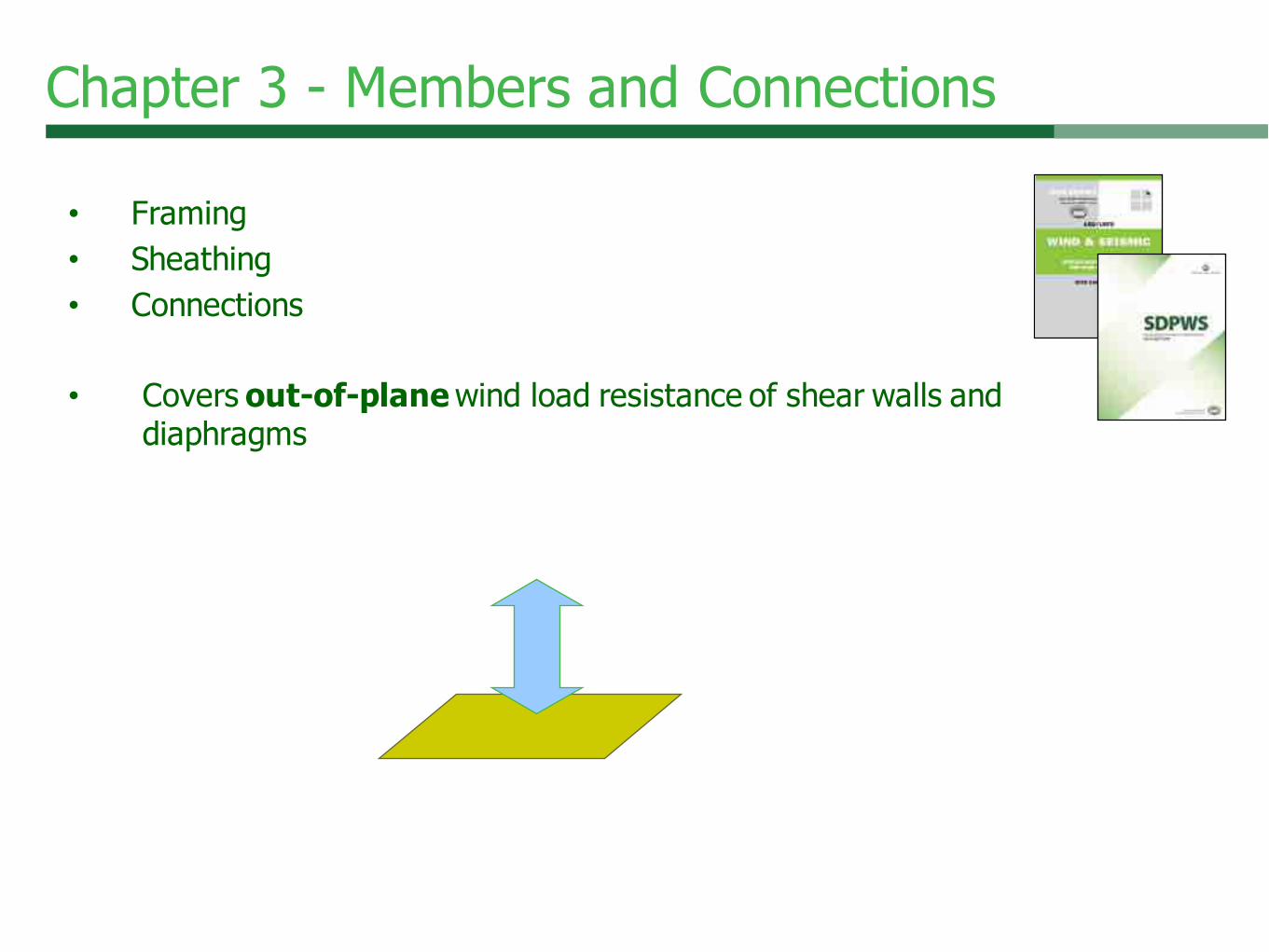
Chapter 3 - Members and Connections
• Framing
• Sheathing
• Connections
• Covers out-of-plane wind load resistance of shear walls and
diaphragms

Chapter 3 - Members and Connections
• Framing – walls
• Accounts for composite action
• Strength and Stiffness
• Applies now to EI
• Up to 24” o.c.
Extension of 1.15 repetitive member factor, Cr
New
Chapter 3 - Members and Connections
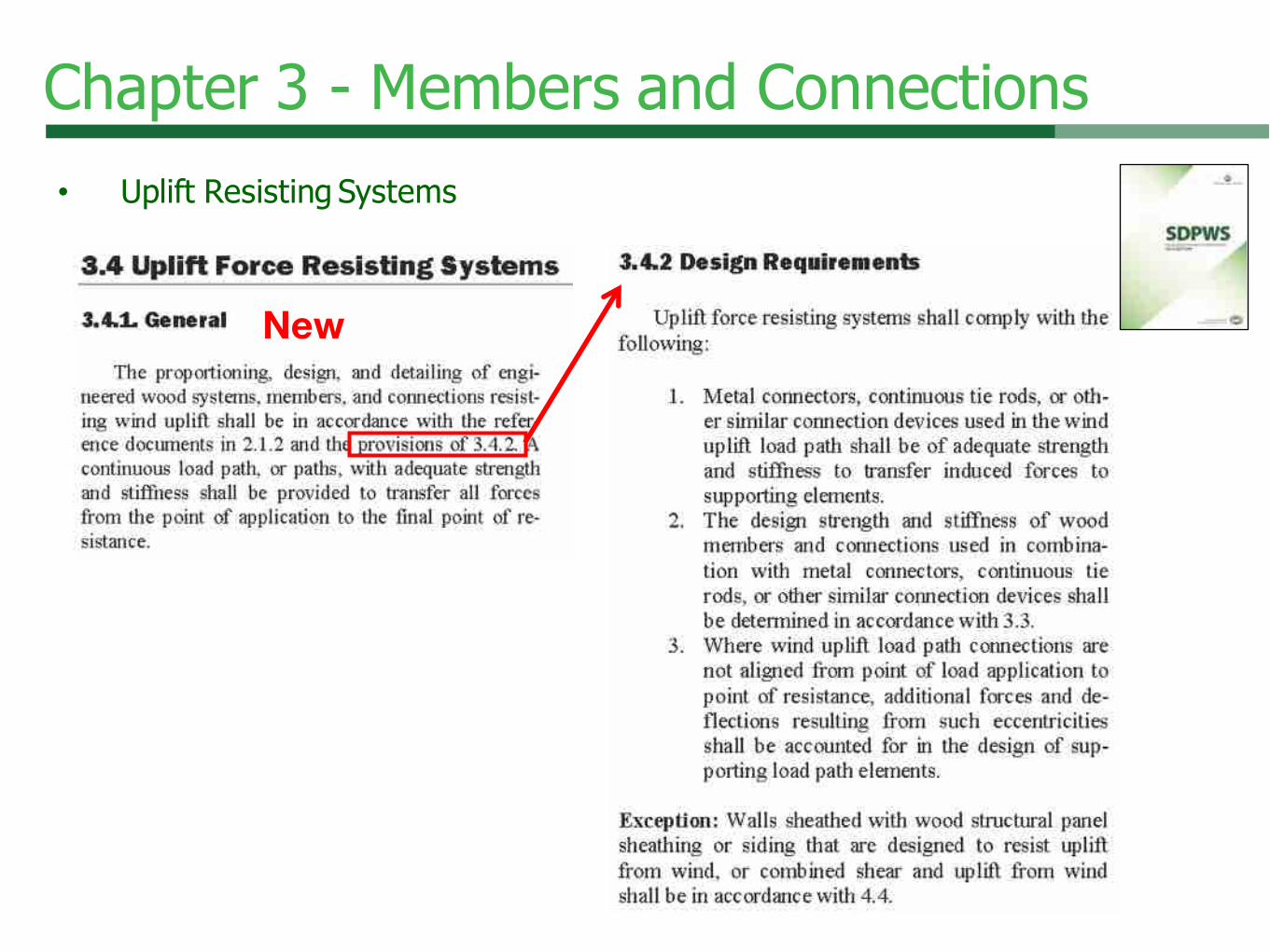
• Uplift Resisting Systems
New

Chapter 3 - Members and Connections
3.4 Uplift Force Resisting
Systems
New

Chapter 4 – Anchorage of Concrete or Masonry Walls
• 4.1.5.1 Anchorage of
Concrete or Masonry
Walls to Diaphragm
• SDC C, D, E, or F
New
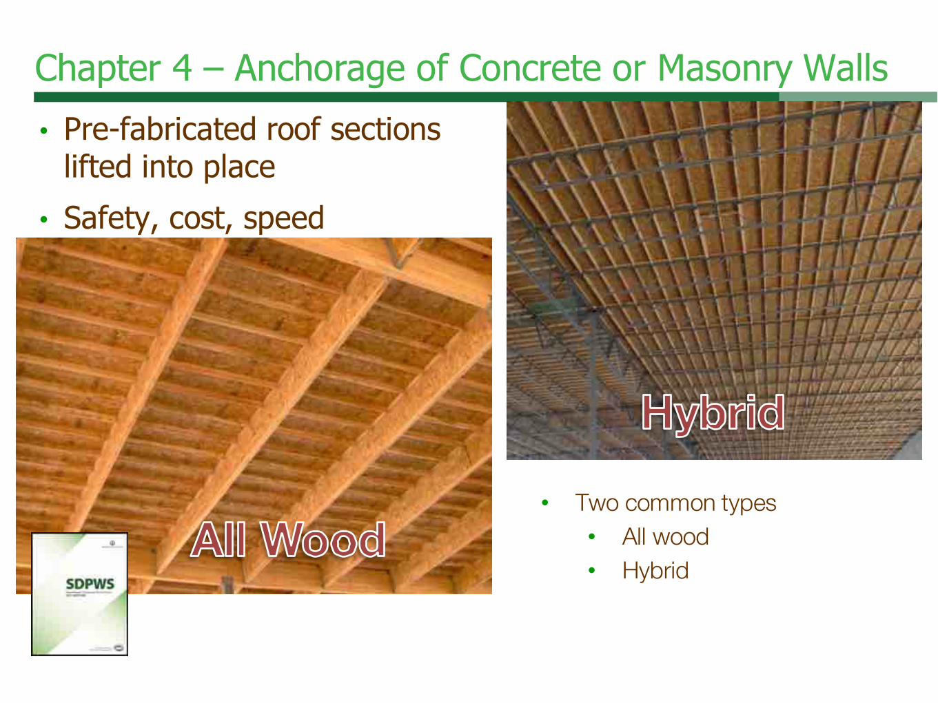
Chapter 4 – Anchorage of Concrete or Masonry Walls
• Pre-fabricated roof sections
lifted into place
• Safety, cost, speed
• Two common types• All wood• Hybrid

Chapter 4 – Nominal Design Value
Revised

Chapter 4 – Nominal Design Value
• Diaphragm Configuration Figures
• Direction with respect to load of• Continuous panel joints• Framing members
• Independent of panel orientation
Revised

Chapter 4 – Horizontal Distribution
Revised
4.2.5 Horizontal Distribution of Shear• Idealized as Flexible
• ASCE 12.3.1.1, or
• DDIAPHRAGM > 2 x DSHEARWALLS
• tributary area
• Idealized as Rigid
• ASCE 12.3.1.2, or
• DDIAPHRAGM < 2 x DSHEARWALLS
• relative lateral stiffness of vertical LFRS• Semi-rigid – complex analysis or “envelope” (NEW)

Chapter 4 - Lateral Force-Resisting Systems
• Torsional Irregularity
• Rigid or Semi-rigid• Torsionally Irregular
• Story Drift DA max > 1.2 DB & C Average

Chapter 4 - Lateral Force-Resisting Systems
Revised
4.2.5.1 Torsional Irregularity• SDC A – Exempt• Rigid or Semi-rigid• WSP diaphragms L/W < 1.5:1• Diagonal Lumber (single or double layer) L/W < 1:1• ΔA max < ASCE 7 allowable story drift
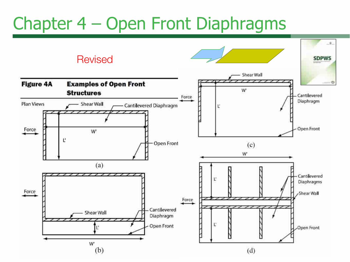
Chapter 4 – Open Front Diaphragms
Revised

Chapter 4 – Open Front Diaphragms
Revised
4.2.5.2 Open Front Structures• Not Torsionally Irregular
• WSP diaphragms L’/W’ < 1.5:1• Diagonal Lumber (single or double layer) L’/W’ < 1:1
• Torsionally Irregular• > 1-story L’/W’ < 0.67:1• 1-story L’/W’ < 1:1

Chapter 4 – Open Front Diaphragms
Revised
4.2.5.2 Open Front Structures• Load parallel to opening - model as semi-rigid or rigid
D A max < ASCE 7 allowable story drift
• L’ < 35’
Exception: Cantilever < 6’ beyond nearest vertical LFRS need not
comply to 4.2.5.2.

Chapter 4 – Open Front Diaphragms
Revised
4.2.5.2.1 Open Front Structures – 1 story
• L’ < 25’
• L’/W’ < 1:1
• Idealized as rigid - distribution of torsional shear
20’
40’

Chapter 4 – High Load Diaphragms
Revised
Blocked Diaphragm Configuration Figures
• Direction with respect to load of
• Continuous panel joints
• Framing members
• Independent of panel orientation
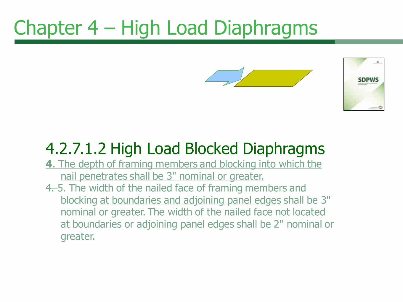
Chapter 4 – High Load Diaphragms
4.2.7.1.2 High Load Blocked Diaphragms4. The depth of framing members and blocking into which the
nail penetrates shall be 3" nominal or greater.
4. 5. The width of the nailed face of framing members and
blocking at boundaries and adjoining panel edges shall be 3"
nominal or greater. The width of the nailed face not located
at boundaries or adjoining panel edges shall be 2" nominal or
greater.

Chapter 4 - Lateral Force-Resisting Systems
• Wood Shear Walls
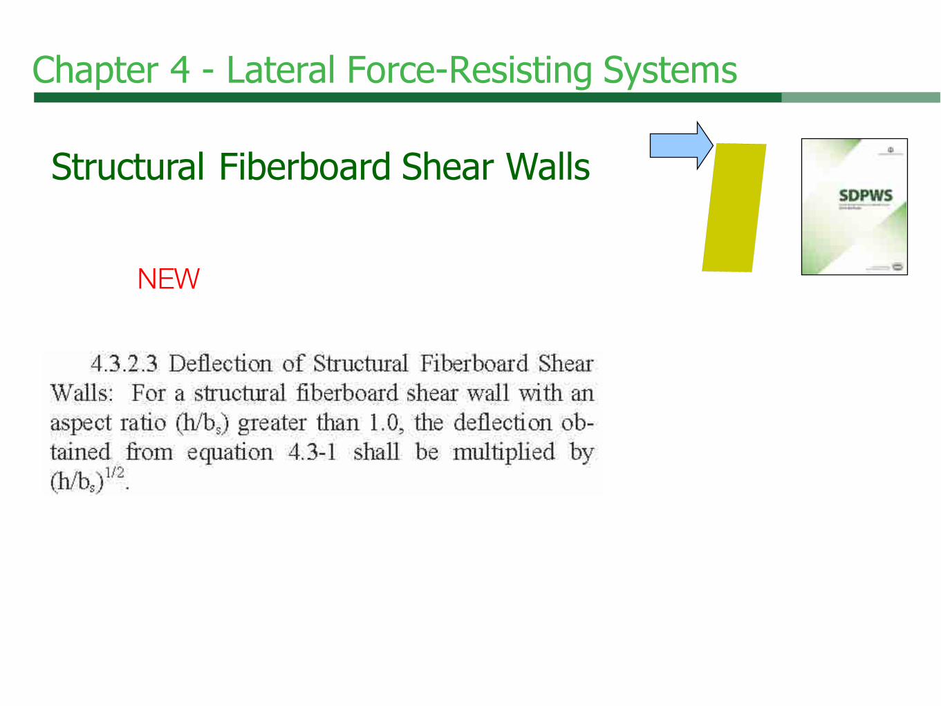
Chapter 4 - Lateral Force-Resisting Systems
Structural Fiberboard Shear Walls
NEW
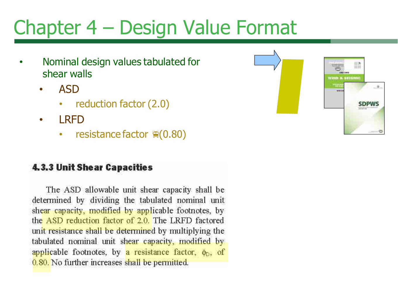
Chapter 4 – Design Value Format
• Nominal design values tabulated for
shear walls
• ASD
• reduction factor (2.0)
• LRFD
• resistance factor f(0.80)

Chapter 4 - Lateral Force-Resisting Systems
4.3.3.4 Shears Walls in a Line:
same materials and construction
4.3.3.4.1 - Individual full height shear walls
provide all same deflection, dswException:
• WSP h/bs > 2:1 vs x 2bs/h
• Fiberboard h/bs > 1:1 vs x (0.1 + 0.9bs/h)
• Shear distribution proportional to capacities
• Shear capacity reduction not combined with
aspect ratio adjustment (4.3.4.2)
2:1 3:1 3½:1
1.00 0.67 0.57
2:1 unless vs = 2(bs/h)
REVISED

Section 4.3.3.2
• Nails 6" panel edge spacing
• Up to 2:1 aspect ratio
• 16' height limit
• Based on cyclic testing
• Shear capacity reduction
Chapter 4 - Unblocked Shear Walls

ubCv
Chapter 4 - Unblocked Shear Walls
Deflection (4.3.2.2)
• Less stiffness
• Deflection amplified
by Cub
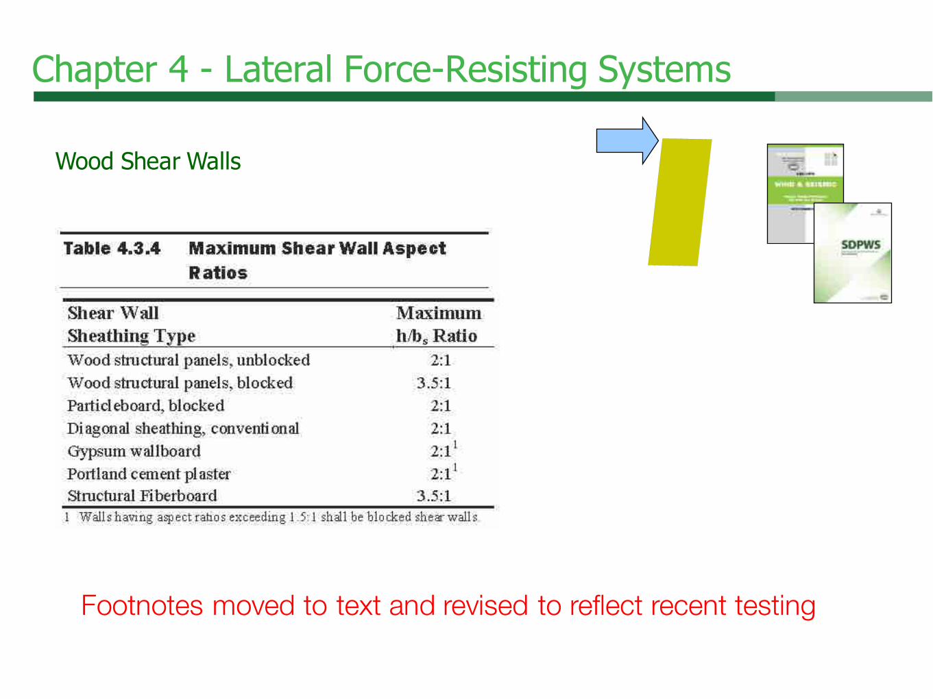
Chapter 4 - Lateral Force-Resisting Systems
Wood Shear Walls
Footnotes moved to text and revised to reflect recent testing

Chapter 4 – Aspect Ratios & Capacity Adjustments
Revised
4.3.4.2 – Shear Wall Aspect Ratio Factors
• h/bs > 2:1 WSP
• vs x (1.25 – 0.125h/bs)
• h/bs > 1:1 Struct. Fiberboard
• vs x (1.09 – 0.09h/bs)
2:1 3:1 3½:1
1.00 0.875 0.813
2:1 unless vs = (1.25 – 0.125(h/bs))

Chapter 4 – Aspect Ratios & Capacity Adjustments
Revised
4.3.4.3 – Perforated Shear
Walls • h/bs > 3.5:1 Not considered
• h/bs > 2:1 Li = L (2bs/h)
• Aspect Ratio Factors (4.3.4.2) do not
apply
• Shear distribution exceptions (4.3.3.4.1)
do not apply

What’s Missing for CLT?
Lateral Design!• ASCE 7 Minimum Design Loads for
Buildings and Other Structures• Response Modification Coefficient, R• CLT not recognized system in ASCE 7
Table 12.2-1
• Options
• Performance-based design
• Demonstrate equivalence to existing
ASCE 7 system
• ASCE 7-10, FEMA P695, and FEMA P795
Quantification of Building Seismic
Performance Factors; Component
Equivalency Methodology
• CLT floors with traditional shear walls78
Outline
79
• ANSI• NDS• SDPWS• WFCM• Summary• More Info
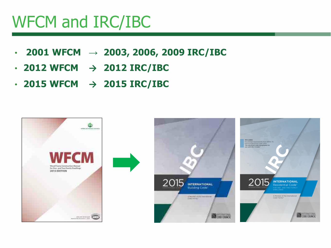
WFCM and IRC/IBC
• 2001 WFCM → 2003, 2006, 2009 IRC/IBC• 2012 WFCM → 2012 IRC/IBC• 2015 WFCM → 2015 IRC/IBC
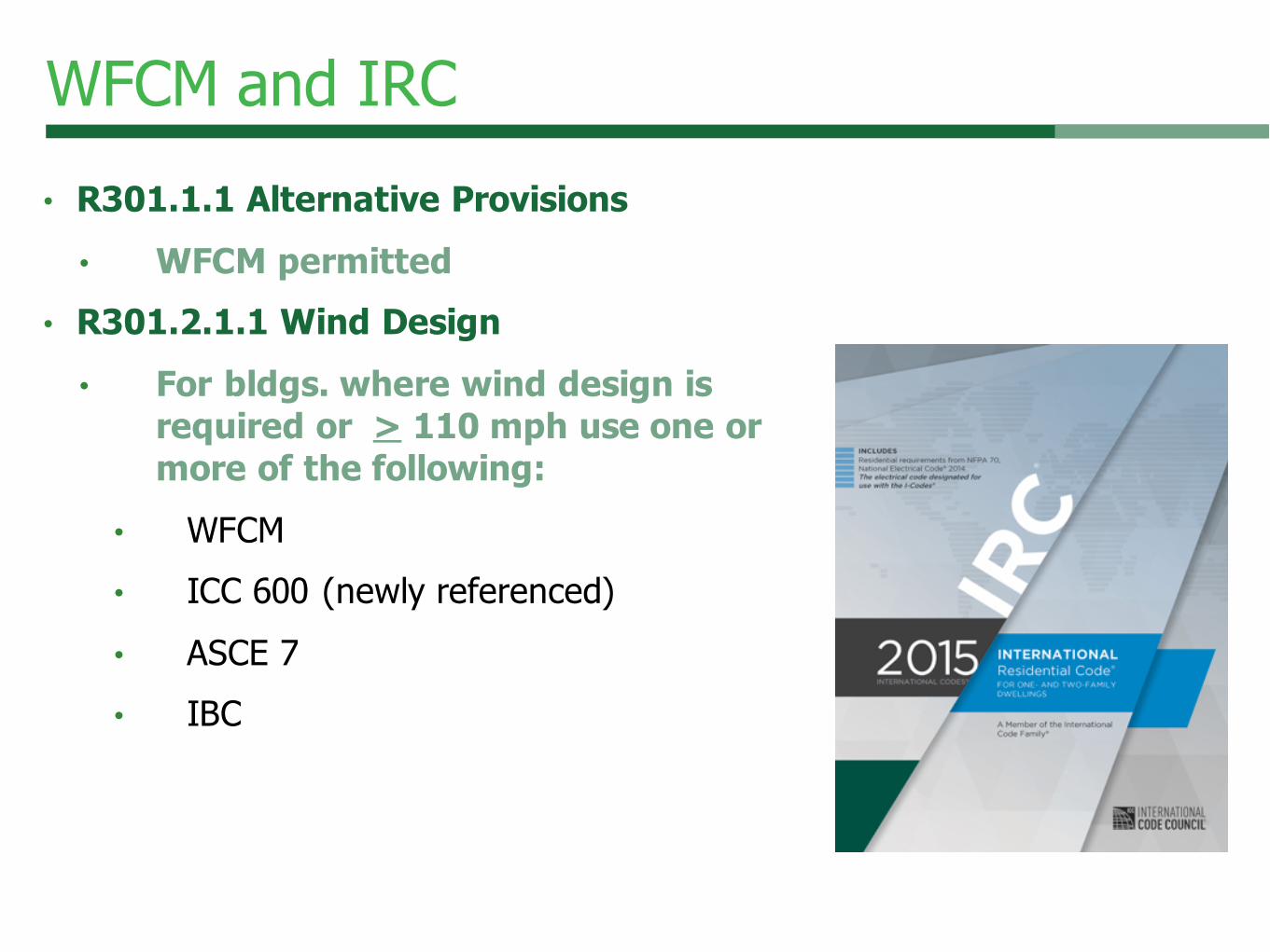
WFCM and IRC
• R301.1.1 Alternative Provisions• WFCM permitted
• R301.2.1.1 Wind Design• For bldgs. where wind design is
required or > 110 mph use one or more of the following:
• WFCM
• ICC 600 (newly referenced)
• ASCE 7
• IBC

WFCM and IBC
• Chapter 16 – Determination of Wind Loads Section of IBC (1609.1.1)• Wind loads in accordance with ASCE 7• Exception: residential structures per
WFCM
• Not used for structures on hills, ridges, or
escarpments
• Chapter 23 – Wood design• 2301.2 & 2309 conventional
construction
2015 IBC
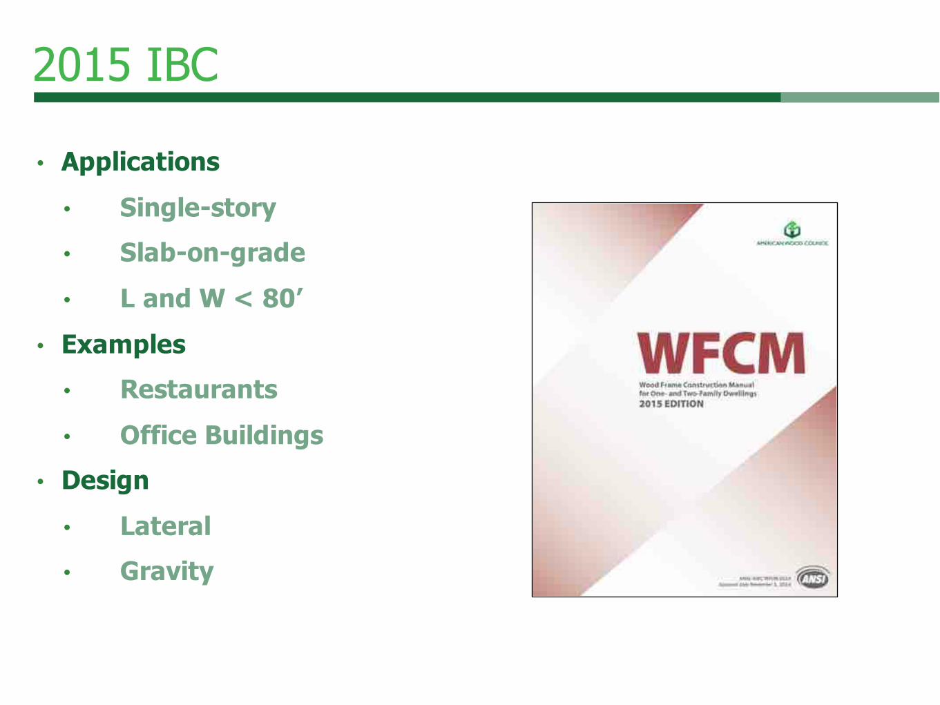
2015 IBC
• Applications• Single-story• Slab-on-grade• L and W < 80’
• Examples• Restaurants• Office Buildings
• Design• Lateral• Gravity

WFCM
• Chapter 1: General• Chapter 2: Engineered Design• Chapter 3: Prescriptive Design• General outline Chapters 2-3
• Connections• Floor systems• Wall systems• Roof systems
• Supplement

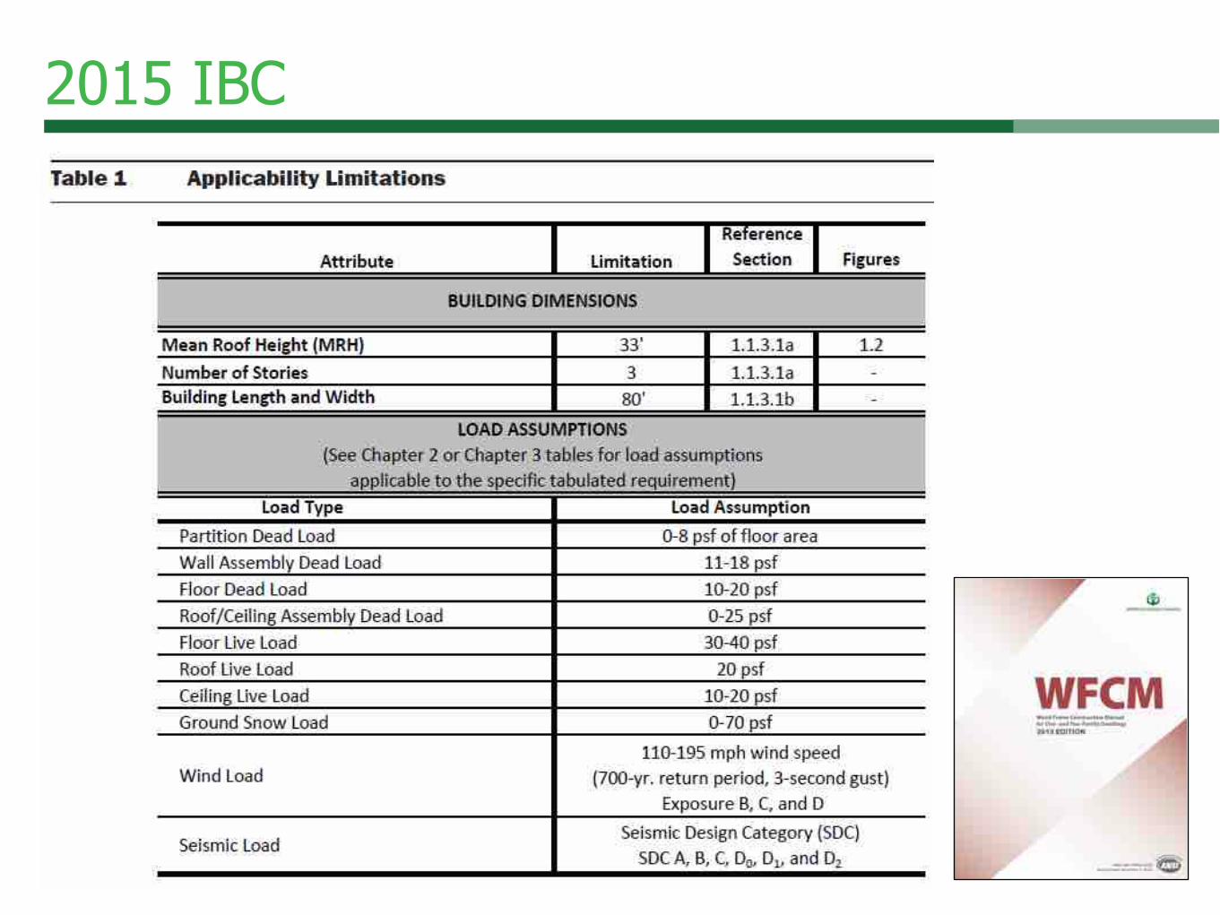
Chapter 1: General
• Mean roof height < 33 ft• < 3 stories• Building length/width < 80 ft• Loads – ASCE 7-10• 0-70 psf ground snow load• 110-195 mph wind speed• 700 yr. return, 3-sec gust, Exp. B, C, D
• Seismic Design Categories• A, B, C, D0, D1, D2
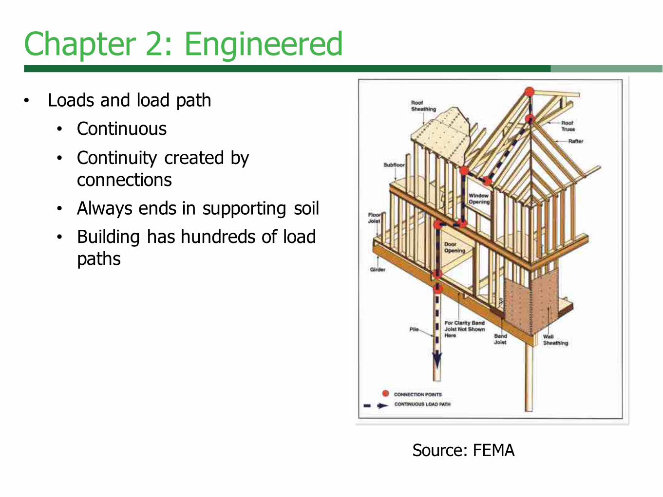
• Loads and load path
• Continuous
• Continuity created by
connections
• Always ends in supporting soil
• Building has hundreds of load
paths
Chapter 2: Engineered
Source: FEMA

Chapter 2: Engineered
• Suction loads

Chapter 3: Prescriptive
• Segmented shear walls - wind

2015 WFCM Changes
• Rafters/Ceiling Joists – Brittle Finishes
New

2015 WFCM Changes
• Header Spans Supporting Roof and Ceiling New

Availability
• www.awc.org• PDF versions• Free view-only
• Buy a printable PDF
• Summer 2015• Commentary
• Printed version
92

• This concludes The American Institute of Architects Continuing Education Systems Course
Questions?
93
www.awc.org