structural design of drydock frontage dredging system
TRANSCRIPT
8/6/2019 Structural Design of Drydock Frontage Dredging System
http://slidepdf.com/reader/full/structural-design-of-drydock-frontage-dredging-system 1/37
STRUCTURAL DESIGN OF DRYDOCK
FRONTAGE DREDGING SYSTEM
PROJECT REPORT
Submitted by
ELDHO PAUL JOBIN JOSE
SREEKUMAR S. VINEESH
T.V.
EXECUTIVE SUMMARY
In the present era of globalization, transportation has an important role, being the
cheapest mode of transport, ships and boats contribute much to business and industry. Their
repair maintenance and manufacturing are carried out in docks. The moment of floating crafts
towards and outward the dock faces the problem of mud deposits on the path. In order to
maintain an accident free dock, these mud deposits are to be removed off periodically. This
process of removal of mud in the ship channels and front portion of the dock is known as
dredging.
In our project we have designed a dry dock frontage dredging system.
1. INTRODUCTION
Dredging is one of the important fields on which major ship yards and ports are
concentrating and spending a lot of money per year. The deposit of mud on ship channels and
front portion of dock, where all the repair works of vessels are carried out is a problem faced by
the port. This will reduce the draft and prevent the vessels from entering the port for berthing
and to the dock for repair works. We concentrate our project on designing the dock frontage
dredging system and by that maintaining a neat and accident free dock.
A cutter suction pump is used to do the dredging operation. A readymade cutter
suction pump is available at the Port Trust. So in our project we have designed a framework to
hold and manipulate the pump. Also a floating platform is designed, on which the frame work is
mounted. This float can be moved very close to the gate so that the regions closer to the gate can
be dredged most effectively.
2. RELEVANCE OF OUR PROJECT
Dock frontage dredging is very important for the accident free functioning of the
dock. The gate of the dry dock remains closed until the repair work or maintenance of the
floating vessels is over. By this time the mud deposits may have reached to a height of nearly
1.5mts in front of the dock gate.
Conventionally the dredging operations at Cochin port trust are done by using a
dredger ship and an L & T Poclain and hopper unit. Both these systems could not dredge the dry
dock region effectively.

8/6/2019 Structural Design of Drydock Frontage Dredging System
http://slidepdf.com/reader/full/structural-design-of-drydock-frontage-dredging-system 2/37
In our project we have concentrated in designing a dredger unit, which
can dredge the dock frontage region most effectively. Also it was found that the mud deposit
does not contain rock particles and the cutter suction pump is most effective for this.
8/6/2019 Structural Design of Drydock Frontage Dredging System
http://slidepdf.com/reader/full/structural-design-of-drydock-frontage-dredging-system 3/37
3. COMPANY'S PROFILE
When the Cochin Port trust was brought under the major port trust act, the activities,of the mechanical engineering department were allocated to the chief engineer. The separate
department was formed only in 1970.
The Mechanical engineering department, headed by the chief mechanical engineer
has a vital role to play in the following areas.
Container terminal
Workshops and Dry dock
Electrical divisions
Internal combustion engines division
The operational and maintenance activities of the equipment at the Rajiv Gandhi
container terminal of the port is looked after by the container terminal division of this
department.
The port workshop and the dry dock is situated at the southern side of the Willington
island, where the vessels come for underwater repairs and maintenance of their hull and
machinery.
Electrical divisions are mainly involved in the distribution of electricity and repair
of electrical equipments and their installation of the port.
The I C engines division of this department carries out major overhauling and
operates a fleet of light equipments like forklift, light duty mobile cranes etc. for cargo handling
operations. The major repairs and overhauling of the land equipments of Port Trust are also
carried out there.■
The mechanical engineering department is also involved in the in the procurement
of the entire minor/major equipments for the cargo/container terminal operation and for the
procurement of floating cranes, vehicles etc.
4. COCHIN PORT TRUST : PORT FACILITIES
Cochin port is an all weather port. A draft of 38ft is maintained in the Emakulam
channel along with berthing facilities, which enable the port to bring in large vessels, in the
Mattanchery channel, the port provides round the clock pilot age to ships subject to certain
restrictions on the size and draft of vessels. There is an efficient network of railways and
waterways and airways connecting the port with other centers spread over the state Kerala,
Tamil Nadu and Karnataka . Facilities for supply of water and bunkering to vessels are also
available.
3
8/6/2019 Structural Design of Drydock Frontage Dredging System
http://slidepdf.com/reader/full/structural-design-of-drydock-frontage-dredging-system 4/37
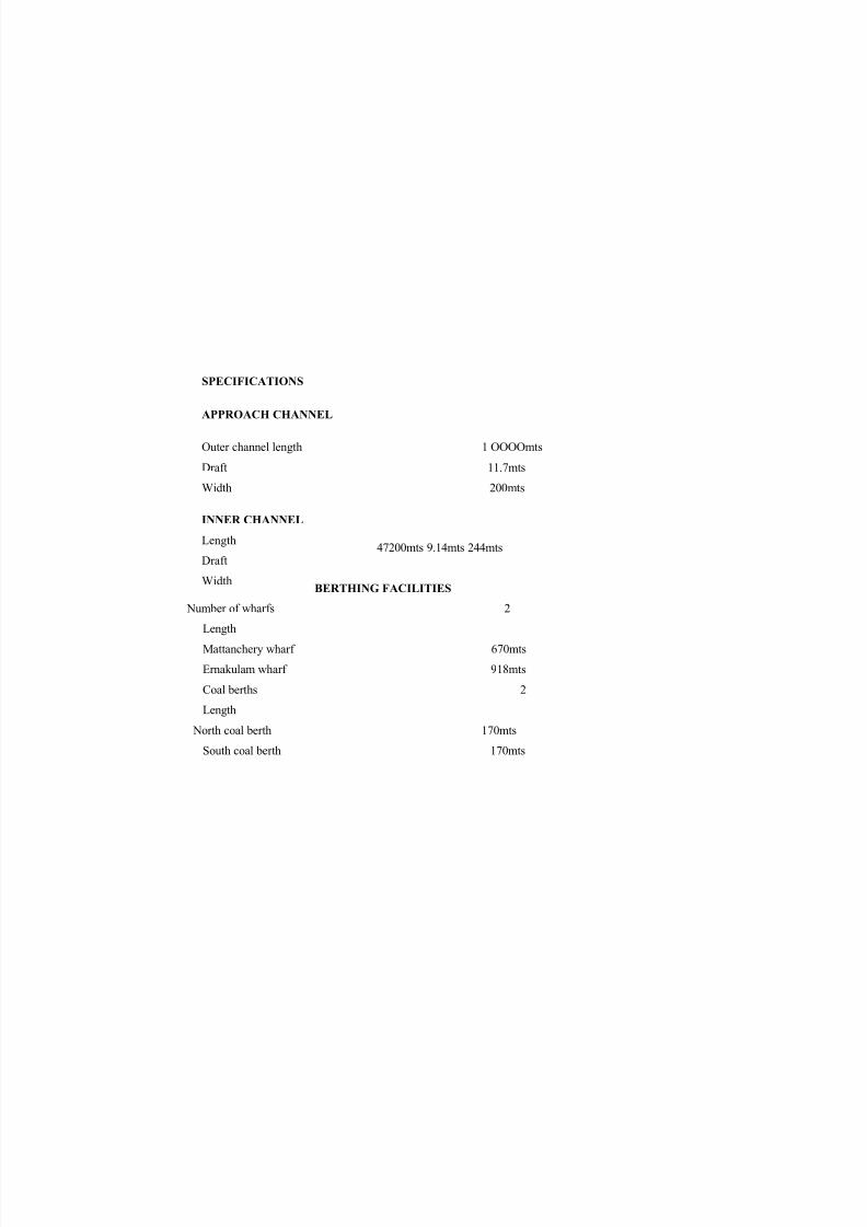
SPECIFICATIONS
APPROACH CHANNEL
Outer channel length 1 OOOOmts
Draft 11.7mts
Width 200mts
47200mts 9.14mts 244mts
BERTHING FACILITIES
Number of wharfs 2
Length
Mattanchery wharf 670mts
Ernakulam wharf 918mts
Coal berths 2
Length
North coal berth 170mts
South coal berth 170mts
4
INNER CHANNEL
Length
Draft
Width

8/6/2019 Structural Design of Drydock Frontage Dredging System
http://slidepdf.com/reader/full/structural-design-of-drydock-frontage-dredging-system 5/37
8/6/2019 Structural Design of Drydock Frontage Dredging System
http://slidepdf.com/reader/full/structural-design-of-drydock-frontage-dredging-system 6/37
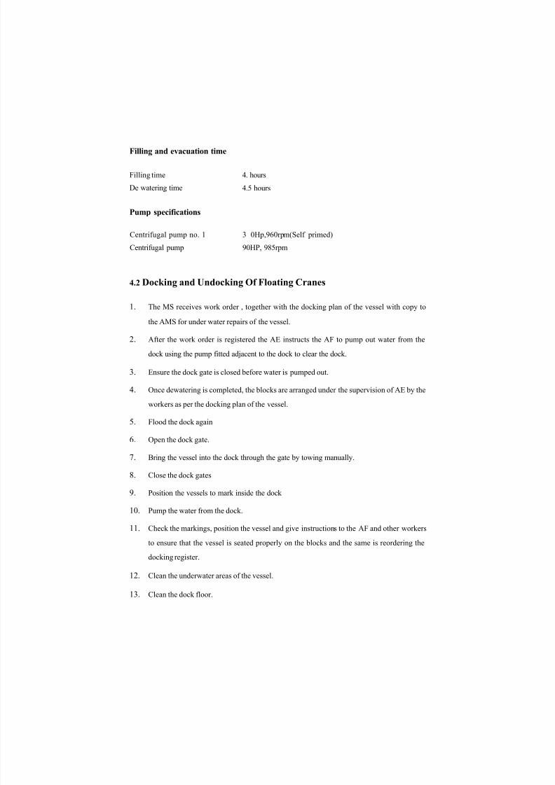
Filling and evacuation time
Filling time
De watering time
4. hours
4.5 hours
Pump specifications
Centrifugal pump no. 1
Centrifugal pump
3 0Hp,960rpm(Self primed)
90HP, 985rpm
4.2 Docking and Undocking Of Floating Cranes
1. The MS receives work order , together with the docking plan of the vessel with copy to
the AMS for under water repairs of the vessel.
2. After the work order is registered the AE instructs the AF to pump out water from the
dock using the pump fitted adjacent to the dock to clear the dock.
3. Ensure the dock gate is closed before water is pumped out.
4. Once dewatering is completed, the blocks are arranged under the supervision of AE by the
workers as per the docking plan of the vessel.
5. Flood the dock again
6. Open the dock gate.
7. Bring the vessel into the dock through the gate by towing manually.
8. Close the dock gates
9. Position the vessels to mark inside the dock
10. Pump the water from the dock.
11. Check the markings, position the vessel and give instructions to the AF and other workers
to ensure that the vessel is seated properly on the blocks and the same is reordering the
docking register.
12. Clean the underwater areas of the vessel.
13. Clean the dock floor.

8/6/2019 Structural Design of Drydock Frontage Dredging System
http://slidepdf.com/reader/full/structural-design-of-drydock-frontage-dredging-system 7/37
J 4. Repair works are carried out as per the work order received.
15. After completion of repairs, AE inspects the vessel and if fit for flooding the AF instructs
to flood the dock. The dock is flooded and the vessel is kept on a float. AMS and the
engineer in charge/master of the vessel carry out a joint inspection.
16. Open the dock door and vessel is taken out of the dock by towing manually or by using
tug.
7

8/6/2019 Structural Design of Drydock Frontage Dredging System
http://slidepdf.com/reader/full/structural-design-of-drydock-frontage-dredging-system 8/37
5. DREDGING
It is process of removing the sludge from the channels of vessels and from the front
point of the dock. The mud is deposited due to various natural phenomena such as flow of
rivers, sea tidal effect and many other reasons. The mud, which is carried out by river water
from remote areas, is deposited in the channels of the ship. This makes difficulty for the ships
and vessels for their travel. So periodical dredging should be carried out.
The Cochin PORT Trust has repair dock. The front portion of the dock consists of a
gate, which faces towards the backwaters. Once the dock gate is closed for repair works the
gates should be reopened only after completion of under water repairs, during this period the
gate is kept closed. Due to natural phenomenon the sludge is deposited in front of the dock and
this makes difficulty in opening the gate as the gate is opened towards the backwaters. The
deposited sludge may have a height of nearly 1.5 meters. Although conventional methods can be
used, the dredging is not perfect. Before each and every docking and undocking operation, the
channels and front side of the dock is dredged.
5.1 Study of dredging
Conventionally various methods are used for dredging . The main methods, which
are used at Cochin Port Trust, are 1. using G.H.D,a dredger ship . 2. By L &T poclain and
hopper unit. 3. By using shovel and floating cranes.
The first method is the major and effective method. This is done by a dredger ship
named "Nehru Sathabdi" Having four 'grabs', operated by four electrical cranes . The cranes
collected sludge in its grabs and deposit it inside the V shaped hoppers, which is situated inside
the ship as a separate unit. The simultaneous operation of four cranes will fill the four hoppers.
This operation would tale nearly two and half-hours of time to fill the hopper. The time
consumption depends on density and
8

8/6/2019 Structural Design of Drydock Frontage Dredging System
http://slidepdf.com/reader/full/structural-design-of-drydock-frontage-dredging-system 9/37

8/6/2019 Structural Design of Drydock Frontage Dredging System
http://slidepdf.com/reader/full/structural-design-of-drydock-frontage-dredging-system 10/37
3. Operation is simple
Limitations:
1. The unit is not self- propelled
2. It can dredge a depth of only 5.85mts
3. Travelling and discharging is time consuming.
These dredging methods are effective, but not much effective for one
specific tasks that is for dry dock frontage dredging.
This led to the requirement of new dredging system, Our project is aimed at
designing a new dredger system for the effective dredging of the dock frontage.
6. NEW DREDGER SYSTEM
The components of the new systems are
A cutter suction pump (dredger pump)
A power winch for the lifting and lowering the pump
A frame work tor the suspension of pump and the winch
Bearings about which the frame work can rotate
A floater
Chain mechanism for rotation of the frame work
Power Control panel
Fenders
Each of the components are explained in detail
10

8/6/2019 Structural Design of Drydock Frontage Dredging System
http://slidepdf.com/reader/full/structural-design-of-drydock-frontage-dredging-system 11/37
11

8/6/2019 Structural Design of Drydock Frontage Dredging System
http://slidepdf.com/reader/full/structural-design-of-drydock-frontage-dredging-system 12/37
Figure 6.2: Side view of the new dredging system
All dimensions are in mts

8/6/2019 Structural Design of Drydock Frontage Dredging System
http://slidepdf.com/reader/full/structural-design-of-drydock-frontage-dredging-system 13/37
6.1 CUTTER SUCTION PUMP
The mud or slurry deposits at the dock frontage and near by regions are found to
have small and only negligible rock particles. It mainly consist of sand grains and mud. Thus a
cutter suction pump is suitable for the dredging operations.
The main components of the dredger pump are the cutter, pump and the
motor.
In cutter suction pump, the cutter head first cuts the deposited mud, diluted it with
water, the booster pump or the dredger pump sucks these diluted mixtures by means of impeller
and makes it into a slurry and delivers. All these operations are combined and performed by
specially designed pump.
The maker of the pump - TOYOTO DENKI INDUSTRIAL CO.LTD, after their
years of experiments and trials, have developed this pump to effectively convert solid mud to a
slurry and pump it off. The delivery hose connected to the delivery pipe of the motor, deposits
this pumped mud to any other regions.
Specification of the pump
13
TypeDP - 10H-1Head20mCapacity0.8m3/minMax. sizesold14mmMotor output7.5kwPoles4Frequency50HzWeight240kg
Table 6.1: Specification of the Pump

8/6/2019 Structural Design of Drydock Frontage Dredging System
http://slidepdf.com/reader/full/structural-design-of-drydock-frontage-dredging-system 14/37
Part List of Type DP Standard Type
No PARTS NAME QTY MATERIAL
t CA3TYRE CABLE
2 CABLE PROTECTION TUBE 1 RUBBER
3 PACKING GLAND 1 EC 250
4 SET RING 1 SS400
5 PACKING RUBBER
5 i SET BOLT 16 SS-iOO
7 IEAD COVER 1 FC250
a PACKING 1 RUBBER
10 HA.vOLE 1 3GP; T UPPER COVER 1 EC 2 50

8/6/2019 Structural Design of Drydock Frontage Dredging System
http://slidepdf.com/reader/full/structural-design-of-drydock-frontage-dredging-system 15/37
11 THERMAL PROTECTOR 1
u fi. HEARING 1
" t S PACKING RU80ER
17 SHAFT 1 SCM135
IB ROTOR t
19 STATOH 1
20 MOTOR CASE 1 SS400
22 SEARING LOCK PLATE 1 S25C
23 R. BE ARI NG , 1
24 T. BEARING
25 BEARING COVER 1 SS40Q
25
27
SET SOLT SS400
MECHANICAL SEAL 1 SET
28 HOUSING t FC250 .
29 PACKINfl 1 RUBBER
30 SHAFT S LEEV E 1 SP. STEELNo. PAHTS NAME QTY MATERIALS
31 OIL SEAL ~\
32 OIL CHAMBER COVER 1 . FCD503
13 PACKING 1 RU9DER3-1 SET DOLT SSJOC
35 UNDER COVER 1 FC250
3S KEY 1 S45C3/ IMPELLER 1 HCR
30 CASING 1 F CO 500
33 IMPELLER COLLAR 1 S25C
40 IMPELLER NUT 1 ss-ioo
41 SUCTI ON CO VER HI;R
42 PACKING _ RUB3ER
43 SET BOLT SUS304
•H ADJUST BOLT . • 3 Sl>S3C-4
45 CUTTER f AN 1 HCR
<S6 STRAINER 1 SS400
4 7 SET BOLT SS400
49 O IL INLET PLU G
51 PACKING 1 RUBBER
52 BENO 1 FCOSOO53 PLATE PACKING 1 RU3BER
54 SET BOLT 4 SS-WT
55. HOSE NIPPLE 1 FC-.'M
56 PLATE PACKING 1 RUDDER
57 SET BOLT 0 SS«.0O
Dimensions of Type DP
TYPE A 81 B2 C D E F F2 H
DP-3 785 636 370 580 350 320 320 103 353
OP-5 K0S 700
DP-7.5-1 850 665 415 400 300 340 '373
DP-7.SB-1 727 425 305 K3 413
DP-tO-1DP-10H-1 (60 Hz)
890 740
OP - 10H - 1 {50 Hz) 786 490 440 44 3
Table 6.2: Part list and Dimensions of type DP
6.1.1 OPERATION OF TOYO DREDCER PUMP
The Toyo Dredging System is very simple in its operation. The pre operation checks
are simple and few;
1. The power supply voltage and frequency should be checked
2. The direction of rotation of the cutter is also to be ascertained.
3. The pipeline is also to be checked for any misalignment.
4. The delivery end should be at a height of at least 2-3mts from the ground level.
The Toyo Pump should be lowered under water level and then started. Then Toyo
Pump has very high initial torque and hence it is found that the starter, which is normally fitted,
has best results both in terms of current reduction as well as torque requirements. One the
required rpm is reached, the power is automatically transferred to the autotransformer. This
usually takes only a fraction of second.
This can be easily established from the ammeter as well as by physically watching
the pump. The pump is totally vibration free and noiseless.
Once the rated rpm is reached, the pump is lowered to the bottom gradually and the
dredging starts. The cutters of the pump rotate and cut the mud and then mix it with water and
produce the slurry, the mixture of mud and water. The system is designed to pump an optimum
concentration of slurry( 15-20% by volume), which can be maintained by operating the rated
amperage. The Toyo Pump model DP 1008 has been found to be the optimum model for
dredging in harbor and minor ports. It can be dredge about 60-72 m3 of solids/hours at an
average static head of 3-6mts and a delivery distance of about 300mts. The distance may be
15

8/6/2019 Structural Design of Drydock Frontage Dredging System
http://slidepdf.com/reader/full/structural-design-of-drydock-frontage-dredging-system 16/37

8/6/2019 Structural Design of Drydock Frontage Dredging System
http://slidepdf.com/reader/full/structural-design-of-drydock-frontage-dredging-system 17/37
7. DESIGN ANALYSIS
■
The floater is the floating member. It is rectangular in shape. All the other
components rest on this floater. It mainly consists of a frame to support the pump and hoist. As
the pump and hoist have a combined weight of approximately 500 kg ie 4905 N, the frame
should have sufficient strength to with stand the forces that will be produced .
Another important factor, which should be taken into account about the floater, is
that the floater should be in proper balance. As the pump is supported on an overlapping frame
the weight of the pump causes an unbalanced condition. More over we have to dredge around
the floater, the frame has to be rotated. This also has to be taken into account while considering
the stability of the floater..
Another factor is that the frame has to rotate carrying the weight, so a rotating
member should be added for smooth rotation.
Size of the floater should be less than the size of the dock; so that easy turning and
rotation of floater inside the dock is possible.

8/6/2019 Structural Design of Drydock Frontage Dredging System
http://slidepdf.com/reader/full/structural-design-of-drydock-frontage-dredging-system 18/37

8/6/2019 Structural Design of Drydock Frontage Dredging System
http://slidepdf.com/reader/full/structural-design-of-drydock-frontage-dredging-system 19/37
This weight W is acting at the beam end. As trail and error method applying taking outer
diameter of beam as 127 mm, inner diameter as 110 mm from standard Is tables.
Outer diameter, D 127 mm
Inner diameter, d 110 mm
self weight w 16.2 kgf/m = 0.15889 N/mm

8/6/2019 Structural Design of Drydock Frontage Dredging System
http://slidepdf.com/reader/full/structural-design-of-drydock-frontage-dredging-system 20/37
7.1.1 BEAM DESIGN

8/6/2019 Structural Design of Drydock Frontage Dredging System
http://slidepdf.com/reader/full/structural-design-of-drydock-frontage-dredging-system 21/37
To find the reaction at the extra support, following procedure is adopted.
Consider only the weight watching at the end of the beam.
rFigure 6.6: Free body diagram of beam The equation for
deflection at any distance 'X' is given by
EIyD = Wv 2 6
= 11.772xl0
3
= 90.85xl03
90.85xl03
2.12 2.13A
(1)
W= 1200x9.81
= 11.772
Now consider the self weight of the beam only. This can be considered as a uniformly acting
load.
21
4.2x
Figure 6.7: Free body diagram of beam

8/6/2019 Structural Design of Drydock Frontage Dredging System
http://slidepdf.com/reader/full/structural-design-of-drydock-frontage-dredging-system 22/37
E Iy D = — { l - x ) A + ---------------D 24V ' 6 24
= 250(2 l)4 I 250x4-23x2-1 25Q (1 2)
4
" 24 V ' ^ 6 24
= 3444
3444x103
yD=+—-— ____________________(2)
EI
Next considering a force R acting as shown below.
1/r
/
R
Figure 6.8: Free body diagram of beam
For this deflection equation is,
EiyD=^[3/-x]
= R&£- [3x4.2-2.1]6 1 J
R(7.717)
EI -----------
(l)+(2)+(3)=0
90.85xl03 + 3.444xl03 - R (7.717)=0 R=
12.22x10³ N
(3)yD =
8/6/2019 Structural Design of Drydock Frontage Dredging System
http://slidepdf.com/reader/full/structural-design-of-drydock-frontage-dredging-system 23/37
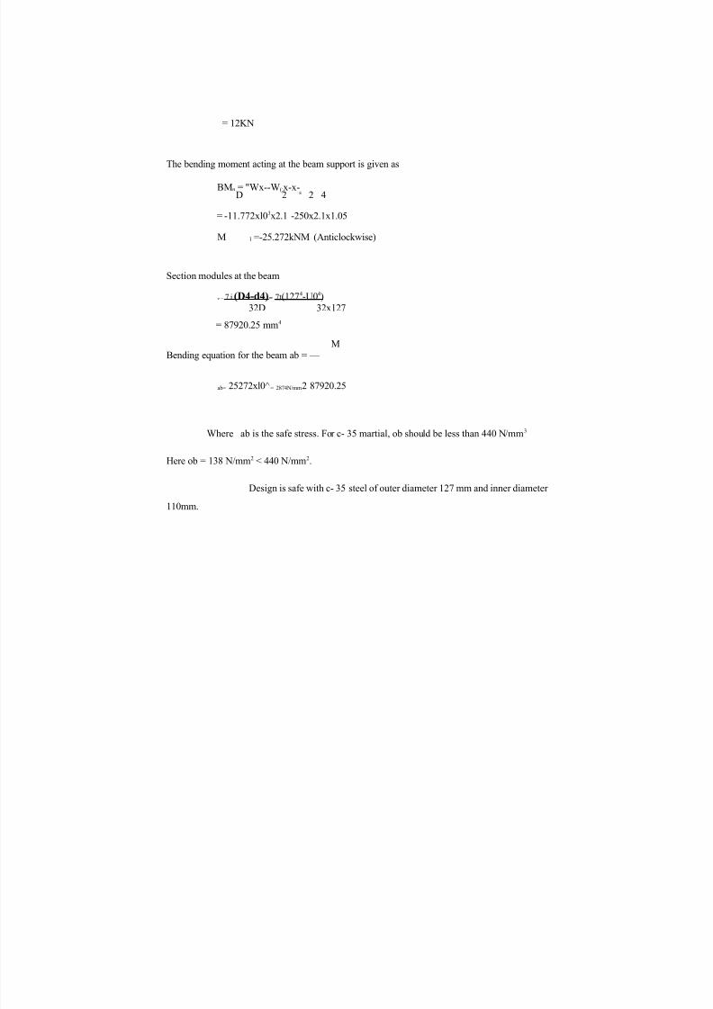
= 12KN
The bending moment acting at the beam support is given as
BMn = "Wx--W(;x-x-D 2 s 2 4
= -11.772xl03x2.1 -250x2.1x1.05
M l =-25.272kNM (Anticlockwise)
Section modules at the beam
z = 7 i (D4-d4) = 7t (127 4 -U0 4
)
32D 32x127
= 87920.25 mm4
M
Bending equation for the beam ab = —
ab= 25272xl0^= 2874N/mm2 87920.25
Where ab is the safe stress. For c- 35 martial, ob should be less than 440 N/mm3
Here ob = 138 N/mm2 < 440 N/mm2.
Design is safe with c- 35 steel of outer diameter 127 mm and inner diameter
110mm.
23

8/6/2019 Structural Design of Drydock Frontage Dredging System
http://slidepdf.com/reader/full/structural-design-of-drydock-frontage-dredging-system 24/37
From Figure
R l = R cosG
= 12 x 103xcos60 =
6xl03
Pj = R 1cos60
= 6x 10³xcos 60 = 3000 N R h
= R 1 cos 30
= 6 x 10³xcos30
= 5196N
Moment due to R h at B, M = R ^ xl
= 5.2x1 =
5.2KNM
= 5.2xl06 NMM
Net moment = 25.27x 10 6- 5.2x106
= 20x 106 Nmm
P2 =20x 106
P!=^I9: =.4761.9N
4200
Slenderness ratio of the column:
7.1.2 COLUMN DESIGN
Figure 6.9: Free body diagram of
column

8/6/2019 Structural Design of Drydock Frontage Dredging System
http://slidepdf.com/reader/full/structural-design-of-drydock-frontage-dredging-system 25/37
considering the column to be fixed at the bottom and free at the other end.
Effective length, Le = 2 L = 2x1000 = 2000mm
Slenderness ratio = —
K
as by trail and error method,
Outer diameter D = 152.4mm
Inner diameter, d = 1 3 5 mm
Self weight, w = 19.6kgf/m
D2+d2
Radius of gyration, K =-----------------= 51 mm
there fore slenderness ration, — = ^999_ = 39 22
K 51
Area = n ( o 2 - d 2 )4
n
/A (l52.42
-1352
) =
3927.6mm2
Then for eccentrically loaded column according to Eulers formula, max. compressive stress,
25

8/6/2019 Structural Design of Drydock Frontage Dredging System
http://slidepdf.com/reader/full/structural-design-of-drydock-frontage-dredging-system 26/37
AP P2.e------1------secA Z
(P
~ A
L x.P-VE I
L = column length = 1000 mm Z =
section modulus K
D 4 -d 4
32D
-----K -----(l52.44 -1354)'32x152.4 v ;
133531.4mm 3
I = Moment of Inertia of section = — (D4 = d4)
64 v ;
71
64(l52.44
-1354)
= 10.18xl06mm4
E- young's modulus = 2x 10 N/mm
EI = 2.035xl012
ac = — +A
3000
3927.6
P P e — + sec A Z
4762
47623927.6 133531.4
Sec 100476
2
EI
o c = 0.764 + 1.212 + 149.8xl =
151.7 N/mm2
Corresponding to this o c steel 88 or C-55 Mn 75 steel can be selected with diameter
Dout = 152.4 mm and Din = 135 mm.
7.1.3 Design of Support Member
Rn 5196N
Length = V 12+1.72
Radius of gyration, K
Taking outer diameter, D Inner
diameter, d
Therefore K
Area
2147 mm D2
+ d2 4
127 mm 110
mm 1272 +
1102
7T(D - d2)
42 mm
7t(127 - 1102)
26
LxiEI
4200+

8/6/2019 Structural Design of Drydock Frontage Dredging System
http://slidepdf.com/reader/full/structural-design-of-drydock-frontage-dredging-system 27/37
Slenderness ratio, Le/K
3164.37 mm2
51.1
Assume C - 35 steel is taken as member material with yield strength,
ay = 280 N/rara2.
Using Johnson's parabolic formula for a columns
buckling load, pc = A ay
r 2~\
Pc 3164.37x280r
280 21472^
4T X2
X 4X 2X 10542
where A
865.5 KN
3164.37 mm2
ay = 280N/mm2
From the designed L =
Pc = 865.5 KN is the K
Safe load that can be n
transmitted through the member E Without
failure
But the load coming on the member in our design in Rn which is only 5.19 KN. The
design with above parameters are safe.
7.2 BEARINGS
The frame work is connected to the float through a bearings. The base of the frame work
is inserted into the journal bearing. The bearing is welded onto a carbon steel casting plate and
this is mounted into the float structure by four bolts and nuts.
Sliding contact journal bearing is used to support the beam. The bearing material
selected is cast iron. The reason for selection of a journal bearing is due to it's minimum
maintenance required, less initial cost etc.
To support the axial load, thrust bearing is used at the bottom.
Lubricant used in the bearings is grease. The reason for selecting grease is due to the
conditions prevailing at the port. There is no high temperature rise in the bearing. Grease can
harmlessly embed the material and does not require much care as in the lubricant oils. Therefore
grease is the ideal lubricant, which can be used here.
Design of bearing for bending
Trial diameters Inner diameter, di =
152.4mm Outer diameter, do = 182 mm
Bearing material is carbon steel casting
Grade 27 - 54
Yield strength of the material ay = 270 N/mm
Factor of safety, F.O.S/ = 2
Working stress [ab] should be less than, ab/F.O.S.
i.e., [ab] < 270/2
< 135 N/mm2
Section modulus, Z = TT/32 (d 04 -d i 4 )
27
2147 mm
40 mm
4 for two ends fixed column 2
x 105 N/mm2
1 - ay (l/K ) 4
7t2 n E

8/6/2019 Structural Design of Drydock Frontage Dredging System
http://slidepdf.com/reader/full/structural-design-of-drydock-frontage-dredging-system 28/37
do
TI/32 (1824- 152.44) 182
3 00.869 x 103 mm3
28
8/6/2019 Structural Design of Drydock Frontage Dredging System
http://slidepdf.com/reader/full/structural-design-of-drydock-frontage-dredging-system 29/37
Bending moment, M = 25.272 x 10⁶ N mm
[ab] = M 25.272 x l O 6 = 83.997 N/mm2
300.869 x 10³
83.997 N/mm2 < 135 N/mm2
Thus the bearing with selected dimensions is safe. Bearing with outer diameter 182 mmand inner diameter 152.4 mm is selected.

8/6/2019 Structural Design of Drydock Frontage Dredging System
http://slidepdf.com/reader/full/structural-design-of-drydock-frontage-dredging-system 30/37
DESIGN OF BOLTS FOR MOUNTING THE BEARING ON THE FLOAT.
C 45 steel bolts are used
No. of bolts
n
Yield strength of bolt in tension
Factor of safety, F
Maximum shear stress, Tmax
Tmax
Net moment acting at the
bearing base, M
Also M
F
380 N/mm'
0.5 x ay = 0.5 x 380
~Y 2.5
76 N/mm2
25.272 x 10⁶ N/mm P x L
25.272 = ' 39/75 x 106
L
L 250
Length of bearing
250 mm 159 x 103 N
L=250
All dimension in mm
Figure : 6.10 Bearing with DimensionsShear force on the bolt, P1 159x10J
Direct shear stress on the bolt, T
'A' = the cross sections area of one bolt
Tensile force, P"
i i and I2 are shown in the figure b = 682
mm I2 = 100 mm
P"
Tensile stressin the bolt, at
ay
2.5
30 bolt x 4
2 (6822+ 1002)
18137.90N P"
8/6/2019 Structural Design of Drydock Frontage Dredging System
http://slidepdf.com/reader/full/structural-design-of-drydock-frontage-dredging-system 31/37
n 4
39750N
nl
39750
(P x L) I, 2( I, 2 + I,2)
(25.272 x 106 x 682
A
18137.90
According to maximum shear stress theory
Tmax = y h + T 2
76 18137.90 + ^39750^
2A
762 1662.06 x 106
A = 536.46 mm2
Corresponding to this cross sectional area, from the standard series of bolts, M #0 coarse
series bolts can be selected.
a\

8/6/2019 Structural Design of Drydock Frontage Dredging System
http://slidepdf.com/reader/full/structural-design-of-drydock-frontage-dredging-system 32/37
Chann
els
Equal angfc
ironFigure 6.11: Frame work of the
float
7.4 DESIGN OF FLOAT
The float is designed as rectangular box type as shown in figure.
7.4.1 Float Design (Structural)
Total Weight
Equal Leg Angles
(4 x 4 )m 2 x 2 + ( l x 4 )m 2 x
4+ (1.3 x 1.3)m2x 1 49.7 m2 48
x 49.7 2385.2 Kg.
Sheet metal used ,
Place thickness = 6 mm
Weight/area = 48 Kgf/m2
Total area of steel metal used =

8/6/2019 Structural Design of Drydock Frontage Dredging System
http://slidepdf.com/reader/full/structural-design-of-drydock-frontage-dredging-system 33/37
Equal leg angle are used at the edges of the float. <90,
90 x 10 angle is selected
Length of Legs A x B
Thickness, 1 Mass, m
Total length used Total weight
Parallel Flange Channel
90 x 90 nun2 10 mm 13.4
kg/m
8 x 4m x 4 x lm + 8 x lm
589.6 Kg
t ,
\t
8 J
MCP 75 channel is selected D
B
Mass
Length of channel used
Total weight
Steel tube used
Outer diameter, D
Inner diameter, d
Weight w
Length
Total weight Total
weight of the float
75 mm 400
mm 7.14
Kg/m
8 x 4 m x 4 x l . 9 m + l x l .3m
40.9 m 7.14x40.9 292.03 Kg
33.7mm
25mm 2.93
kgf/m l m
2.93 x 1-2.93 Kg
2385.2 + 590 + 292.03 + 2.93
3270.16 Kg
Fencing used = 100 Kg
Extra weight = 100 Kg
Total weight of frame and load 2m x 19.6 Kg/m + 4.2m x
16.2 Kg/m + 1200 Kg.
1307.24 Kg
Weight of 3 person 3 x 70 = 210 Kg
Net weight = 4987 Kg
48926 N

8/6/2019 Structural Design of Drydock Frontage Dredging System
http://slidepdf.com/reader/full/structural-design-of-drydock-frontage-dredging-system 34/37
7.4.2 Float Design
Total weight of the float i.e. W
48926
Thus, Depth of immersion
Center of gravity of float, G
Center of buoyancy, B
weight of water displaced
Density of sea water x volume of
water displaced x 9.81
1025 x 4 x 4 x (depth of
immersion) x 9.81
304.10mm
500mm from bottom
(Depth of immersion)
Area moment of inertia, I +
304.10 2
152.1 mm from bottom
bxd 3
b - d
21.13 x 10i3 mm4
Volume of immersed part, VArea x depth of immersion
1 0 0 x 4 0 0 0 x 3 0 4 .
1 4.86 x 106mm3
Distance BG500.152.1
347.9 mm
M is the metacentric point. M is the point about which the body tills or
oscillates when an unbalanced force acts pm the body.
Distance, GM = 1/V BG
GM
Also GM
2.13 x 10¹³
4.86 x 10⁹
4034.8 mm
(wx)
WT an G
347.9
12
400mm

8/6/2019 Structural Design of Drydock Frontage Dredging System
http://slidepdf.com/reader/full/structural-design-of-drydock-frontage-dredging-system 35/37
(wx) - moment acting =
W - total weight
25.272 x KfNmm
48926N
0 - Angle of tilt when the load is applied Tan 6
9
For the safety of float, BM > BG Here BM
BG
Clearly BM >BG
Float is in a state of stable equilibrium
Float
7.5 MECHANISM OF ROTATING BEAM
The beam is to be rotated 360° at a rate of 1 rpm. The mechanism used for is a chain
drive. The reason for selecting chain drive is due to its simple construction, easy installation,
comparatively lower cost and less maintenance required.
Design Procedure
Speed ratio selected = 3
Type of Chain = Roller chainFrom PSG design data, for gear ratio of 3, number of tooth on sprocket of pinion, Zi =
24.
Pitch selected, P
Centre distance between the
two sprockets, s Teeth
on sprocket of wheel Diameter
of small sprocket di
Diameter of
large sprocketd2
Linear velocity of
the chain V
(wx)
W * GM
25.272 x 10⁶
48926 x 4034.8
0.128
7.29°
BG + GM
4382.7 mm
347.9 mm
Water Level
Figure 6.12 Float in stable Equilibrium G-Centre of gravity
B-Centre of
buoyancy M-
Metacentre
Water Level
8/6/2019 Structural Design of Drydock Frontage Dredging System
http://slidepdf.com/reader/full/structural-design-of-drydock-frontage-dredging-system 36/37
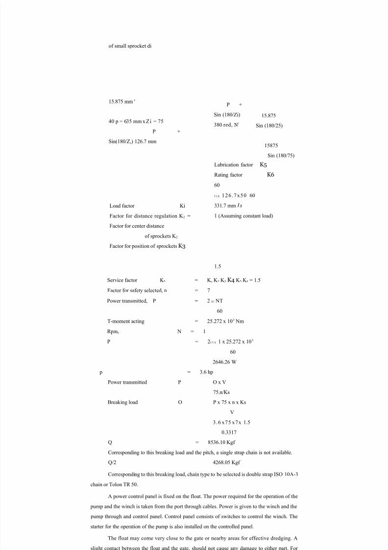
15.875 mm '
40 p = 635 mm x Zi = 75
P +
Sin(180/Z,) 126.7 mm
P +
Sin (180/Zi)
380 red, N!
15.875
Sin (180/25)
15875
Sin (180/75)
Load factor Ki
Factor for distance regulation K 2 =
Factor for center distance
of sprockets K 2
Factor for position of sprockets K3
Lubrication factor K5
Rating factor K6
60
T I X 126 .7x50 60
331.7 mm I s
1 (Assuming constant load)
1.5
Service factor K 5 = K, K 2 K 3 K4 K 5 K 6 = 1.5
Factor for safety selected, n = 7
Power transmitted, P = 2 TC NT
60
T-moment acting = 25.272 x 10³ Nm
Rpm, N = 1
P = 2T T X 1 x 25.272 x 103
60
2646.26 W
p = 3.6 hp
Power transmitted P O x V
75.n/Ks
Breaking load O P x 75 x n x Ks
V
3.6 x75 x7x 1.5
0.3317
Q = 8536.10 Kgf
Corresponding to this breaking load and the pitch, a single strap chain is not available.
Q/2 4268.05 Kgf
Corresponding to this breaking load, chain type to be selected is double strap ISO 10A-3
chain or Tolon TR 50.
A power control panel is fixed on the float. The power required for the operation of the
pump and the winch is taken from the port through cables. Power is given to the winch and the
pump through and control panel. Control panel consists of switches to control the winch. The
starter for the operation of the pump is also installed on the controlled panel.
The float may come very close to the gate or nearby areas for effective dredging. A
slight contact between the float and the gate, should not cause any damage to either part. For
this, a synthetic rubber fender is fixed along the outer perimeter of the float. This fender
8/6/2019 Structural Design of Drydock Frontage Dredging System
http://slidepdf.com/reader/full/structural-design-of-drydock-frontage-dredging-system 37/37
provides a cushioning effect and protects the float and any other object in cases of a slight
collision.
8. ALTERNATE USE FOR THE NEW SYSTEM
Although we have designed the dredger system specifically for the dock frontage
dredging. It can be used for other purposes also. The system has been designed in such a way
that the entire frame work can be detached from the float at the bearings.
Thus when there is no dredging, work, the frame work and the chain mechanism can be
detached. The float can be use for carrying loads. The maximum load carrying capacity of the
float after the removal of framework, pump and chain mechanism is 1.3 tons
9. CONCLUSION
The limitations of the conventional dredging systems for dry dock frontage
dredging were studied and a new system was designed. During its design safety, cost and
availability of material were considered. Thus the new system is used to dredge the dock
frontage regions most effectively. The system can also be used for other purposes.
10. REFERENCES
1. Modi, Dr. P. N; and Seth, S.M., Hydraulics and Fluid Mechanics, Standard Book House;
15th ed., 2004
2. Khurmi, R.S., Machine design, 1st Multicolor ed.m, S. Chand, 2005
3. Gupta, Dr. A.B, Practical Hand Book for Mechanical Engineers,9th ed., Galgotia
publications, New Delhi, 2002
4. Ramamrutham, s, Strength of Materials, 11th ed., Dhanpat rai & Sons, 2000
5. PSG Design Data Book