structural fasteners in wood-to-wood connections - … plans/tables, references... · structural...
TRANSCRIPT

Structural Fasteners in Wood-to-Wood Connections
“The Wood Products Council” is a Registered Provider with The American Institute of Architects Continuing Education Systems (AIA/CES). Credit(s) earned on completion of this program will be reported to AIA/CES for AIA members. Certificates of Completion for both AIA members and non-AIA members are available upon request. This program is registered with AIA/CES for continuing professional education. As such, it does not include content that may be deemed or construed to be an approval or endorsement by the AIA of any material of construction or any method or manner of handling, using, distributing, or dealing in any material or product.
Questions related to specific materials, methods, and services will be addressed at the conclusion of this presentation.
Copyright Materials
This presentation is protected by US and International Copyright laws. Reproduction,
distribution, display and use of the presentation without written permission of the speaker is
prohibited.
© The Wood Products Council 2012
Learning Objectives
At the end of this program, participants will be able to:
1. Articulate how wood properties, loading direction and dowel bearing strength
affect the strength of wood connections.
2. Understand the features and strength properties of traditional nails, screws,
lags and bolts and the newest fastener- Structural Wood Screws.
3. Understand the procedures involved in determining the imposed loads and
selection of the appropriate fastener.
4. Locate and understand the code requirements for specific wood-frame
structural connections.

Introductions Brice Hereford
Code Compliance Specialist Construction Experience Certified Sustainable Designer ICC Adjunct Instructor
Welcome
Introductions Who’s in the Room?
Inspectors, Plan Review Architects, Engineers Builders, Contractors, Developers Other
Welcome
OMG
Largest Domestic Screw Manufacturer Agawam, MA
Since 1979
Who We Are

OMG
OMG / FastenMaster Principles Contractor Focused
Lower Installed Cost Train the Chain (Contractor, Yard, Inspector, Engineer)
Code Reliance Clear Installation Instructions, Technical Bulletins Inspectability Tested to Standards (ICC, ASTM, FM)
Innovation Develop New Products Key to Staying Relevant and in the USA
Today’s Topics
Critical Wood Properties Fastener Basics The “Evolution of Fasteners” New Category of Structural Wood Screws
Resources Referenced
NDS – National Design Specification for Wood Construction – the “Bible” Wood Properties – Strengths, Span Tables, etc Fastener Strengths In Wood (Connection Design)
Resources Referenced
IRC – Residential Code IBC – Commercial Building Code
Your State Code
Resources Referenced
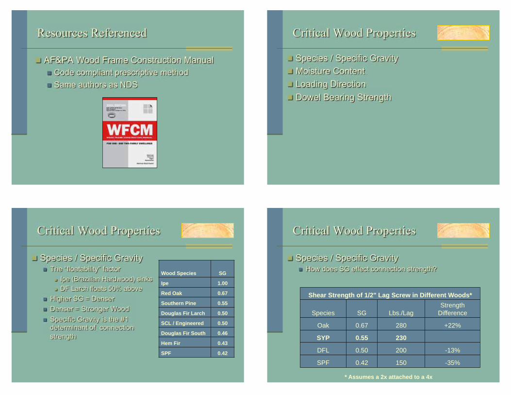
AF&PA Wood Frame Construction Manual Code compliant prescriptive method Same authors as NDS
Critical Wood Properties
Species / Specific Gravity Moisture Content Loading Direction Dowel Bearing Strength
Critical Wood Properties
Species / Specific Gravity The “floatability” factor
Ipe (Brazilian Hardwood) sinks DF Larch floats 50% above
Higher SG = Denser Denser = Stronger Wood Specific Gravity is the #1 determinant of connection strength
Wood Species SG Ipe 1.00 Red Oak 0.67 Southern Pine 0.55 Douglas Fir Larch 0.50 SCL / Engineered 0.50 Douglas Fir South 0.46 Hem Fir 0.43 SPF 0.42
Critical Wood Properties
Species / Specific Gravity How does SG effect connection strength?
Shear Strength of 1/2" Lag Screw in Different Woods*
Species SG Lbs./Lag Strength
Difference
Oak 0.67 280 +22%
SYP 0.55 230
DFL 0.50 200 -13%
SPF 0.42 150 -35%
* Assumes a 2x attached to a 4x

Critical Wood Properties
Wet vs. Dry Wood Moisture Content
If 19% or Less = “DRY” to engineer If above 19% = “WET”
The wetter the wood, lower the connection strength Must be compensated for by engineer:
Per NDS 10.3.3 “When connections are exposed to wet service conditions in use, reference design values must be multiplied by the wet service factors ”
Critical Wood Properties
Wet vs. Dry Wood How does it effect connection strength?
Design Strengths in SYP
Load Type Fastener Type Dry
(Lbs) Wet Service
Factor Wet
(Lbs)
Shear ½” Lag 230 .70 161
16d Nail 154 .70 108
Withdrawal ½” Lag 437 .70 306
16d Nail 75 .25 19
Loading Direction Parallel to Grain vs. Perpendicular to Grain
Which connection is stronger?
Load Direction
Grain Direction
Parallel to Grain Loading Perpendicular to Grain Loading
L L L L
G
G L
G
Critical Wood Properties
Loading Direction Parallel to Grain is actually stronger!
Load Direction
Grain Direction
Parallel to Grain Loading Perpendicular to Grain Loading
410 lbs. 230 lbs.
( Design Shear of ½” Lag Screw in SYP )
Critical Wood Properties

Critical Wood Properties
Dowel Bearing Strength Ability for the wood above the fastener to support the fastener
¼” 3/8” ½” ¾”
Which one of these holes supports the least weight?
Critical Wood Properties
Dowel Bearing Strength
¼” 3/8” ½” ¾”
5150 psi 4200 psi 3650 psi 2950 psi
Larger the hole, weaker the wood!
Fastener Facts
Anatomy of Nails / Screws Metal Strength Properties Design Strength Properties in Wood Evolution of Fasteners
Fastener Facts
Anatomy of Nails / Screws
Head Style Shank/Blank Diameter (Gauge) Point Style
Threads Per Inch (TPI) Minor Thread & Major Thread Diameter

Fastener Facts
Metal Strength Properties
Shear Strength – Lbs needed to slice metal Approx 1,500 Lbs * #8 deck screw
Tensile Strength – Lbs to stretch until break metal Approx 2,500 Lbs *
Bending Yield – Lbs to bend metal beyond elastic Approx 125,000 psi *
Used to compare fasteners only Not suitable for designing the connection
Fastener Facts
Design Strength Properties
Design Shear Strength Approx. 150 lbs. * #8 deck screw in SYP
Design Withdrawal Strength Approx 100 lbs. per inch of thread embedded *
Design Head Pull-Through Strength Approx 100 lbs. per inch of wood under head
Takes into account fastener and wood interaction Only value used by designer/engineer Include Safety Factor (2.5 – 5 times)
Fastener Facts
Safety factor? Who cares about a safety factor?
Fastener Facts
Ledger Connection
35 people
Stair Stringer Connection 1 guy
Handrail Connections At least 6 “leaners”

Fastener Facts
Quick “Live Load” Analysis
Guests weigh 6200 lbs. Deck designed to carry 7700 lbs.
Only 1500 lbs. (7 people + 1 keg) away from anticipated live load.
The safety factor creates a buffer for inconsistencies in materials and usage.
Fastener Facts
Design Shear Strength Maximum pounds of shear load that can be safely applied before fastener or wood is displaced
Fastener Facts
Design Withdrawal Strength Maximum pounds of withdrawal load that can be safely applied before threads disengaging from the wood
Fastener Facts
Design Pull-Through Strength Maximum pounds of withdrawal load that can be safely applied before head begins to pull through side member

Evolution of Fasteners
Wooden Dowels Nails and Spikes Wood Screws Lag Screws Through Bolts Structural Wood Screws
Evolution of Fasteners
Wooden Dowels Ship building Post & beam Timber frame
Evolution of Fasteners
Nails - Benefits Easy to install – one tool / no special skills needed Contractor familiarity – common nomenclature Pneumatic capability – faster by far Inexpensive – cheapest method Accepted design values in NDS
Evolution of Fasteners
Nails - Drawbacks Tough to determine size from head Difficult to identify fastening pattern once installed Common disregard for fastening patterns

Evolution of Fasteners
Nails – Biggest Drawbacks #1 – Very low withdrawal strength #2 – Made worse when exposed to moisture (75% reduction in strength!)
Evolution of Fasteners
Very low withdrawal strength Unacceptable in many code applications
(Ledgers) 2009 IRC: R502.2.2
Evolution of Fasteners
Wood Screws Deck screws NOT drywall screws!!
Evolution of Fasteners
Wood Screws - Benefits Easy to install
No pre-drilling Cordless drills & impact drivers
Threads add greater withdrawal strength vs. nails Values in NDS
Shear & Withdrawal

Evolution of Fasteners
Wood Screws - Drawbacks Unknown quality
95% imports No strengths printed on box Most not ICC vetted (no report)
Coating claims unchecked “ACQ Approved”? QC Process Accountability
Evolution of Fasteners
Wood Screws - Drawbacks Shear strength and ductility dependent on proper heat treat Most imported screws are through-hardened
Through Hardened Case Hardened
Carbon cooked, brittle potential Carbon-rich case, ductile core
Evolution of Fasteners
Lag Screws – Benefits Easy to find. Available in all sizes. Greater strength than screws or nails Strengths reported in the NDS Code allowed / preferred
Evolution of Fasteners
Lag Screws – Drawbacks By code, must pre-drill twice
75% of diameter for entire length 100% of diameter for unthreaded portion
Second pre-drill step commonly ignored by the installer Nearly impossible to inspect!

Deck Collapse Injures Scores - Ledger splits from faulty lag screw installation
July 30, 2004. Diamond Horseshoe Casino in Polson, Montana. 34 injured, 3 critically, 4 life threatening
Post-failure inspection found "lag screws were too few and far between, and they were driven through the ledger with a rotary hammer rather than through pre-drilled holes, which induced a splitting force”
Evolution of Fasteners
Lag Screws – Drawbacks By design, lags are threaded 2/3rds of their length: Creates Board jacking = weaker joint, easier moisture entry
Side Main
Threads in shear plane - the weakest part of the screw in the most critical part of the application
Evolution of Fasteners
Evolution of Fasteners
Through Bolts – Benefits Best withdrawal strengths of all Requires pre-drilling – can’t cheat Easy to identify Accepted values in NDS
Evolution of Fasteners
Through Bolts – Drawbacks Difficult to install
Drilling required Three tools needed for installation Expensive – 4 pieces of hardware
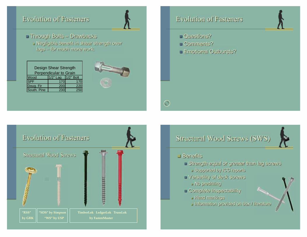
Evolution of Fasteners
Through Bolts – Drawbacks Negligible benefit in shear strength over lags – for much more work:
Wood 1/2" Lag 1/2" BoltSPF 170 170Doug. Fir 200 220South. Pine 230 250
Design Shear Strength Perpendicular to Grain
Evolution of Fasteners
Questions? Comments? Emotional Outbursts?
Evolution of Fasteners
Structural Wood Screws
Structural Wood Screws (SWS)
Benefits Strength equal or greater than lag screws
Supported by ICC reports Versatility of deck screws
No predrilling Complete Inspectability
Head markings Information provided on box / literature

Structural Wood Screws (SWS)
Approved as an Alternative As with all non-commodity products, allowable under the Alternative Materials provision R104.11 (IRC & local code).
Tested to national standards (ANSI, ASTM) Third party, peer reviewed reports (ICC-ES) Demonstrate equivalency to code
Structural Wood Screws (SWS)
Drawbacks New: Contractors need better instruction Not a commodity. Small differences between competitors. New: Limited familiarity by code officials
Structural Wood Screws
What To Look For National Code Report (ICC-ES or IAPMO)
Documented Metal Strength Properties Shear, Withdrawal, Pull through Values in Wood Lot Traceability via Head Stamp and Packaging QC Audit Process
Corrosion Statement Hot Dipped Galvanized to ASTM A153 Mechanically Galvanized to ASTM B695 Class 55 Tested under ICC-ES AC257– Equal to HDG
Technical Literature Installation Instructions Application-Specific Technical Bulletins
Common SWS Applications
Multiple Ply Engineered Wood Beams (LVL, LSL, PSL) Deck Ledger to Rim Rafter & Truss to Top Plate

Multiple Ply EW Beams
Supported by EW: I-Level (was TrusJoist) Boise, GP, LP Roseburg, Others
In some Design Software
Boise (BC Calc) Keymark
Multiple Ply EW Beams

Multiple Ply EW Beams
Technical Bulletins Code Compliance Proper Installation Limitations
Multiple Ply EW Beams
Technical Bulletins Proper Size Selection Minimum Edge / End Distances
Multiple Ply EW Beams
Technical Bulletins Fastening Patterns – Top Loaded Beams Fastening Patterns – Side Loaded Beams
Deck Ledger to Rim

Deck Ledger to Rim
Code History Prior to 2003 – No direction at all 2003 IRC – Limited nail use 2006 IRC – Same: no nails or toe nails
Forced the installer & inspector to become the engineer!
10 ft.
5 ft.
Deck Ledger to Rim
Calculating the Load Live load = 40 psf of deck surface (R301.5) Dead load = 10 psf (R301.2.2.2.1) Combined load = 50 psf Take half the distance to the 1st support (5ft) Multiply by Combined Load (5ft x 50psf) This load (250plf) must be supported at Ledger
10 ft.
5 ft.
Deck Ledger to Rim
Calculating the Fastening Pattern (w/ 2x SPF Rim)
½” Lag supports 170 lbs per fastener in shear 170/250 = .68 (1 lag every 8”)
SWS (LedgerLok) supports 210 lbs 210/250 = .85 (1 SWS every 10”)
Waaay too much work
Deck Ledger to Rim
Welcome the 2009 IRC (502.2.2) Requirements and Restriction under one section Allows for alternative materials and methods Gives actual fastening patterns!!!
If you’re not there yet – you will be soon.

Deck Ledger to Rim
Technical Bulletins Code Compliance Proper Installation Limitations
Deck Ledger to Rim
Technical Bulletins Code compliance statement ACQ testing to ICC information
Deck Ledger to Rim
Technical Bulletins Minimum Edge / End Distances PE Approved Fastening Patterns
Deck Ledger to Rim
Technical Bulletins Installation Requirements & Restrictions

Evolution of Fasteners
Very low withdrawal strength Unacceptable in many code applications
(Ledgers) 2009 IRC: R502.2.2
2007/2009 IRC Code
This section allows Structural wood Screws

Comments by Glenn Mathewson- Building inspector in Westminster Colorado in an article in November 2009 PROFESSIONAL DECK BUILDER
“ As written in the code, the lateral connection detail shall be permitted; it isn’t a requirement.
Throughout the International Codes, the phrase shall be permitted is used only to clarify when a detail seemingly prohibited by a general statement is actually permitted in a specific application.
He goes on to say:
Section R104.11 of the IRC even states: The provisions of this code are not intended to prevent the installation of any material or to prohibit any design or method of construction not specifically prescribed by this code.
Therefore, it’s not necessary to specifically “permit”
a design in the code unless it could be confused as being “prohibited." That's obviously not the case for Figure R502.2.2.3, as it’s unlikely that any building official would prohibit a connection like it.
ACTUAL ORIGIN OF THIS SECTION IN CODE CYCLE!!

Rafter / Truss to Top Plate Rafter / Truss to Top Plate
Rafter - Code Requirements 2-16d toe nailed per IRC Table R602.3(1) Or 3-8d toe nailed per IBC table 2304.9.1
Rafter / Truss to Top Plate
Rafter - Code Requirements 2-16d toe nailed per IRC Table R602.3(1) Or 3-8d toe nailed per IBC table 2304.9.1
IRC (2x16d)
IBC (3x8d)
NDS Withdrawal Value 26 21 lbs/inch/nail Embedment Depth 2.5 1.5 inches Toe Nail Factor 0.67 0.67 Wind/Seismic Load Duration 1.6 1.6 Amount of Nails 2 3
140 100 lbs/connection
Rafter / Truss to Top Plate
Truss - Code Requirements Trusses shall be connected to wall plates by the use of approved connectors having a resistance to uplift of not less than 175 pounds and shall be installed in accordance with the manufacturer’s specifications. 3-16d commons will accomplish this, getting 178 pounds of design uplift. (From the Truss Plate Institute & Structural Building Component Association).

Withdrawal Value 131 lbs/inch of thread Embedment Depth 2.0 inches Toe Nail Factor 0 Wind/Seismic Load Duration 1.6 Amount of Screws 1
420 lbs/connection
Rafter / Truss to Top Plate Rafter / Truss to Top Plate
Rafter / Truss to Top Plate
IBC IRC
100 140 365 420
Loads in SPF
100 150 200 250 300 350 400 450 500
Rafter / Truss to Top Plate

Rafter / Truss to Top Plate

Rafter / Truss to Top Plate
Four ways to evaluate for substitution: - In wind zones less than 110 (or 100 in hurricane prone regions), this method exceeds code outright! - Where stated loads on truss plan are called out, use Table 1 - Where ties specified, compare Table 1 to tie mfr. loads - Specify using AFPA Wood Frame Construction Manual
Rafter / Truss to Top Plate
Withdrawal Value 131 lbs/inch of thread Embedment Depth 2.0 inches Toe Nail Factor 0 Wind/Seismic Load Duration 1.6 Amount of Screws 1
420 lbs/connection
Rafter / Truss to Top Plate
Connection Design Uplift Lateral Shear H2.5 365 130 130 H3 320 105 140 H4 235 140 135 H5 265 100 170
TimberLok 420 320 320
Rafter / Truss to Top Plate

Rafter / Truss to Top Plate
Has your office received this yet?
ECCENTRIC LOADING OR TOP PLATE ROLL - Clemson U- 1995
• From research done by Clemson U in the 1990’s it was discovered that Hurricane Ties need to be attached to the outside of the structure, preferably to the framing (under the OSB) to fulfill stated load requirements. • Interior installation (SOP) reduces the value by 60%. This reduces the value of the H-2.5 from 365 to 146(SPF). About the same value as its lateral and shear values of 130. This is also the minimum required by code with 2 16D nails at 140lbs.
• Lastly, in the footnote U to the installer it states that” When installing Hurricane Ties on the inside of the wall, special considerations must be taken to prevent condensation on the inside of the walls ”
Structural Wood Screws eliminate Top Plate Roll

SHEAR or BRACED WALLS
You are basically building a two story shear wall!
USE STRUCTURAL WOOD SCREWS INSTEAD OF LAGS, THRUBOLTS OR BIG 60d SPIKES

Next Step in the Evolution of Fasteners!
THINK OF NEXT?
CRAZY SCREW GUYS!
WHAT WILL THEY

CARRYING BEAM
Other Applications?
What other challenges do you see out there?
This concludes The American Institute of Architects Continuing
Education Systems Course
Questions?
BRICE HEREFORD
1-800-518-3569
413-537-4219
Wood Products Council 866.966.3448 [email protected]

Thank You!
Technical Assistance 800-518-3569
www.fastenmaster.com
LOS ANGELES CITY RESEARCH REPORT # 25738 INTERNATIONAL CODE ICC ESR # 1078 MIAMI-DADE APPROVAL # 08-0425.09 FLORIDA STATE APPROVAL # FL 4261