structural floor & roof systems
TRANSCRIPT

Canadian Precast/Prestressed Concrete Institute
DESIGNING WITH PRECAST CONCRETEStructural Floor &
Roof Systems
TECHNICAL GUIDE

2 Structural Floor & Roof Systems
Table of Contents
DISCLAIMER: Substantial effort has been made to ensure that all data and information in this publication is accurate. CPCI cannot accept responsibility of any errors or oversights in the use of material or in the preparation of engineering plans. The designer must recognize that no design guide can substitute for experienced engineering judgment. This publication is intended for use by professional personnel competent to evaluate the significance and limitations of its contents and able to accept responsibility for the application of the material it contains. Users are encouraged to offer comments to CPCI on the content and suggestions for improvement. Questions concerning the source and derivation of any material in the design guide should be directed to CPCI.
Canadian Precast/Prestressed Concrete InstitutePO Box 24058 HazeldeanOttawa, OntarioCanadaK2M 2C3
Telephone (613) 232-2619 Toll Free: 1-877-YES-CPCI (1-877-937-2724)
E-mail: [email protected]
www.cpci.ca
About Structural Precast Concrete . . . . . . . . 3
Floors & Roofs . . . . . . . . . . . . . . . . . . . . . . . . 4
Double Tee Slabs . . . . . . . . . . . . . . . . . . . . . 13
General Requirements Hollow Core
Slabs and Double Tee Slabs . . . . . . . . . . . . 17
CPCI Members . . . . . . . . . . . . . . . . . . . . . . 20
CPCI Resources . . . . . . . . . . . . . . . . . . . . . . 21
CPCI Certification . . . . . . . . . . . . . . . . . . . . 22
Precast Concrete and the Environment . . . . 23
3Structural Floor & Roof Systems
About Structural Precast Concrete
SpeedStructural precast concrete elements are manufactured under strictly controlled plant conditions at the same time as foundation work is being prepared on site. When the site is ready, the precaster can immediately commence with the erection of precast components, dramatically shortening construction time. This reduces on-site congestion, and financing costs, while accelerating the occupancy date.
Quality/DurabilityThe lasting benefits of precast concrete are inherent; high strength, high density, quality controlled precast concrete is superior to other building products for durability, corrosion resistance, impact resistance, fire resistance, security and low maintenance. The assurance of precast concrete product quality is achieved through environmentally controlled manufacturing conditions, a skilled workforce and a stringent inspection program. Precast concrete is CPCI Certified in accordance with the requirements of both CSA A23.4 “Precast concrete–materials and construction” and the United States PCI MNL 116 “Manual for Quality Control for Plants and Production of Structural Precast Concrete Products”. When precast concrete is prestressed, the additional benefits of uncracked sections enhancing durability and lighter sections leading to an increased slenderness of construction can be realized.
Long Spans/Heavy LoadsPrestressing keeps the concrete in compression, minimizes cracking and increases the load carrying capacity. High quality plant cast/controlled concrete produced with optimum curing conditions translates to a high strength, high quality product resulting in increased load capacities and more efficient sections.
Structural Precast/Prestressed Concrete FlexibilityCustom manufactured precast units are easily incorporated into a building to accommodate non-typical shapes or sizes. Precast elements can be designed for removal and/or reuse to accommodate future building expansion and renovations.
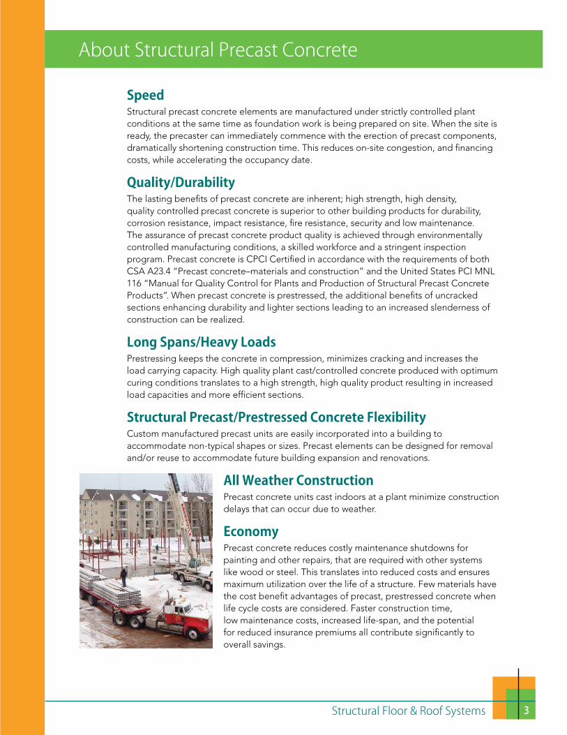
All Weather ConstructionPrecast concrete units cast indoors at a plant minimize construction delays that can occur due to weather.
EconomyPrecast concrete reduces costly maintenance shutdowns for painting and other repairs, that are required with other systems like wood or steel. This translates into reduced costs and ensures maximum utilization over the life of a structure. Few materials have the cost benefit advantages of precast, prestressed concrete when life cycle costs are considered. Faster construction time, low maintenance costs, increased life-span, and the potential for reduced insurance premiums all contribute significantly to overall savings.

4 Structural Floor & Roof Systems
Floors & Roofs
Hollow Core SlabsHollow core slabs are produced using patented dry cast or extrusion systems with low slump concrete extruded through a machine. The concrete is compacted around cores that are formed with augers or tubes. The continuous slab voids can be used as heating/cooling ducts and as chases for electrical wiring. Hollow core slabs also reduce sound transmission and vibrations between floors and eliminate floor squeaks and movement that are typical with wood construction.
ApplicationsHollow core slabs are available from CPCI members all across Canada. Hollow core slabs can be used for most applications requiring a solid floor or roof system. Schools, office buildings, condominiums, hotels, senior citizen’s apartments, commercial buildings, residential dwellings, houses of worship, nursing homes and educational facilities are all ideal applications. For hotels, motels and apartments, the hollowcore slabs are oriented to either span between load bearing shear walls or to span from a central corridor to the exterior walls.
Slabs can be cantilevered under typical residential floor loading. Consult your local CPCI producer for specific design assistance with cantilevers, and the CPCI Design Manual (latest edition).
Durability Note: Hollow core is produced using no-slump, dry-cast concrete. It is not recommended to use slabs for exterior residential applications when the slabs are directly exposed to moisture and freeze/thaw cycles (exterior balconies, etc.) due to the low air entrainment properties of no- slump concrete. Hollowcore can be used in these environments provided the necessary protection is provided, including a waterproofing membrane and a durable concrete topping wearing surface. Alternatively, other precast solid flat slabs can be manufactured to accommodate air entrainment for freeze/thaw durability for exterior use without the need for an additional concrete topping.

5Structural Floor & Roof Systems
SizesModular precast concrete floor and roof slabs are machine manufactured under controlled conditions in modern precast plants. Slabs are typically 1220 mm nominal width and depths can range from 152 mm, 203 mm, 254 mm, 305 mm, and 355 mm—consult your local CPCI member for available sizes.
ManufacturingFor efficiency, slabs are cast on long line beds; normally these casting beds are 100 m to 200 m long. Slabs are then cross-cut at 90° to the exact length for each project. Angle cuts are also possible. The most economical building layout is achieved when the plan dimensions of the hollow core bays fit the slab module, typically 1220 mm. Non-module plan dimensions can be accommodated using partial width slabs.
PrestressingHollow core slabs are prestressed. This means long spans, shallow depth and the ability to carry heavy loads are easily accommodated, and this also allows for better space planning and a lower floor/floor height. Lengthening the span may be more economical (fewer slabs to make and install). Maximum span/depth ratios of 45 are recommended for floors. CPCI member’s load tables define the allowable live load that a given slab can safely support in addition to the slab self weight. The load capacity is a function of the slab thickness, the amount of prestressing provided and the location of the prestressing strands. The CPCI Design Manual also offers guidance.
Consult your local CPCI member for the sizes/capacities in your area.254 and 305 slab depths often governed by vibration at longer spans
Slab thickness: Spans up to:
152 mm 7.5 m
203 mm 11 m
254 mm 13 m
305 mm 14 m
355 mm 16 m
Maximum Hollowcore Spans

6 Structural Floor & Roof Systems
Prestressed Hollow Core Slabs
Contact your local CPCI member for specific sizes, span/loading and detailing information.
Spans up to 7.5 m
Spans up to 11 m
Spans up to 13 m
Spans up to 14 m
Spans up to 16 m
152 mm slab
203 mm slab
254 mm slab
305 mm slab
355 mm slab

7Structural Floor & Roof Systems
Comparative thermal inertia of various building materials
Use of Slab VoidsHollow core slabs are cast with continuous voids to reduce cost and weight. When properly coordinated for alignment, the voids in the hollow core can be used as electrical or mechanical ducts. For example, routing of a lighting circuit through the cores will allow fixtures to be located in an exposed slab ceiling without an unsightly surface mounted conduit.
Thermal MassSlabs detailed to distribute heated air through the cores can take advantage of the thermal mass in a passive solar application. From an operating energy perspective, the thermal inertia of heavy materials such as concrete is well known, both in warm and cold climates.
TermobuildTermobuild (www.termobuild.com) is a thermal mass system developed in Scandinavia in the 1970s. The circular voids in precast concrete hollow core flooring and roof slabs are connected to air-handling ducts, that pump clean fresh air into the building, expelling the old air, and radiating warm air in the winter and cool air in the summer, to significantly reduce energy consumption.
Finished CeilingHollow core, because it is cast on smooth steel forms, has a smooth finished underside. The smooth ceiling provided by a hollow core slab requires only caulking of the longitudinal joints. The underside of slabs can be used as a finished ceiling as installed by applying textured paint or an acoustical spray if required.

8 Structural Floor & Roof Systems
Bearing Supports for Hollow CoreHollow core slabs can be supported on many types of structural systems designed to carry the required dead and live loads. Precast beams, precast walls, cast-in-place concrete beams and walls, masonry walls, insulated concrete forming system walls, wood and steel stud walls and structural steel beams are all suitable for use as load bearing systems with hollow core slabs—consult your local CPCI member for details.
CSA A23.3 specifies a minimum bearing dimension of 50 mm (larger dimensions may be required depending on spans, loads, tolerances, and supporting material).
For bearing hollow core on wood walls, it is recommended that a steel stud track plate be used at the top and bottom of all wood bearing walls in lieu of the traditional double wood top plate and single bottom plate. This will eliminate the possibility of wood top plate crushing under the weight of the slabs and the cumulative shrinkage that occurs in a multi-storey wood stud wall.
Recommended detailing of non-load bearing wood walls:a) interrupt floor to floor by the hollow core, orb) eliminate the wood plates in these walls if the wood
wall is a multi-storey wall (running by each hollow core floor).
This will eliminate differential shrinkage in the wood wall between the bearing and non-load bearing wood walls.
Hybrid Composite Beams are typically a combination of concrete and steel cross sections. The composite effect of concrete and steel can enhance the properties of the section compared to traditional girders and result in longer spans, slimmer floors and in some cases integrated fireproofing. These beams are used when the headroom is critical or when a flat soffit is required since they are usually shallower than concrete beams. The bottom flange of composite beams will usually serve as bearing for the precast concrete slabs.
Holes and OpeningsHoles and openings larger than 150 mm diameter should be located on the approved shop drawings. Openings can be provided in hollow core systems by forming or sawing the openings in the plant or by installing short slabs with steel hangers at the jobsite. In laying out openings for a project, the least structural effect will be obtained by orienting the longest dimension of an opening parallel to a span, or by coring small holes that cut the fewest prestressing strands. Do not cut any reinforcing or web without prior approval of the precast slab manufacturer and engineer. Installing large openings after a floor or roof deck has been installed and grouted, by shoring and saw cutting, should be done only if unavoidable.

9Structural Floor & Roof Systems
Bearing Supports for Hollow CoreHollow core slabs can be supported on many types of structural systems designed to carry the required dead and live loads. Precast beams, precast walls, cast-in-place concrete beams and walls, masonry walls, insulated concrete forming system walls, wood and steel stud walls and structural steel beams are all suitable for use as load bearing systems with hollow core slabs—consult your local CPCI member for details.
CSA A23.3 specifies a minimum bearing dimension of 50 mm (larger dimensions may be required depending on spans, loads, tolerances, and supporting material).
For bearing hollow core on wood walls, it is recommended that a steel stud track plate be used at the top and bottom of all wood bearing walls in lieu of the traditional double wood top plate and single bottom plate. This will eliminate the possibility of wood top plate crushing under the weight of the slabs and the cumulative shrinkage that occurs in a multi-storey wood stud wall.
Recommended detailing of non-load bearing wood walls:a) interrupt floor to floor by the hollow core, orb) eliminate the wood plates in these walls if the wood
wall is a multi-storey wall (running by each hollow core floor).
This will eliminate differential shrinkage in the wood wall between the bearing and non-load bearing wood walls.
Hybrid Composite Beams are typically a combination of concrete and steel cross sections. The composite effect of concrete and steel can enhance the properties of the section compared to traditional girders and result in longer spans, slimmer floors and in some cases integrated fireproofing. These beams are used when the headroom is critical or when a flat soffit is required since they are usually shallower than concrete beams. The bottom flange of composite beams will usually serve as bearing for the precast concrete slabs.
Holes and OpeningsHoles and openings larger than 150 mm diameter should be located on the approved shop drawings. Openings can be provided in hollow core systems by forming or sawing the openings in the plant or by installing short slabs with steel hangers at the jobsite. In laying out openings for a project, the least structural effect will be obtained by orienting the longest dimension of an opening parallel to a span, or by coring small holes that cut the fewest prestressing strands. Do not cut any reinforcing or web without prior approval of the precast slab manufacturer and engineer. Installing large openings after a floor or roof deck has been installed and grouted, by shoring and saw cutting, should be done only if unavoidable.
FasteningsSuspended ceilings, crane rails, mechanical and electrical equipment and other sub- systems can be accommodated with standard manufactured hardware and embedded plates.
Underfloor Radiant HeatUnderfloor radiant heat uses the floor to heat the building above by raising the floor temperature until the heating output of the floor matches the amount of heat that the building is losing. Radiant heating systems use a boiler or hot water heater to heat water (or an antifreeze solution) which is circulated through in-floor tubing. Precast floor slabs are ideal for use with radiant heating. A topping slab containing radiant heating tubes is cast over hollow core or double tee floor slabs. This can also be achieved with embedded electrical wires in the topping.
Load DistributionHollow core slabs are designed as individual, one way, simple span slabs. When the slabs are installed and grouted together at the keyways, the connected individual slabs become a system that behaves similarly to a monolithic slab. A major benefit of the slabs acting together is the ability to transfer forces from one slab to another. In most hollow core slab deck applications, non-uniform loading occurs in the form of line loads, concentrated loads, or load concentrations at openings. The ability of individual slabs to interact with adjacent slabs allows these load concentrations to be shared by the adjacent slabs.

10 Structural Floor & Roof Systems
Connections to Masonry/Steel/Precast
Note: All connections shown are to be used for concept design only. Contact your local CPCI producer member to confirm specific standard connections.

11Structural Floor & Roof Systems
Balcony Details & Connections to Structural Wood or Steel
Note: All connections shown are to be used for concept design only. Contact your local CPCI producer member to confirm specific standard connections.

12 Structural Floor & Roof Systems
DiaphragmsA series of hollow core slabs can resist lateral loads in the form of a grouted slab assembly, provided proper connections and details are incorporated The function of a diaphragm is to receive wind loads, seismic loads and lateral earth pressures from the building elements and transmit these loads to lateral force-resisting elements that carry the loads to the foundation.
Top Surface PreparationUntopped hollow core slabs are the most economical system. The top surface of untopped hollow core slabs can be prepared for the direct installation of floor coverings by applying a cement-based skim coat to the top surface of the slabs. Non-structural leveling concretes can be applied ranging from 3 to 50 mm thick depending on the material used, or by casting a composite structural concrete topping.
Structural toppings are often used in high seismic zones and where heavy loadings are to be supported. A rough finish can be created on the top surface of the hollow core, just after the slabs have been extruded, to improve the bonding of the structural topping.
Fire ResistanceHollow core slabs provide excellent fire resistance. Fire ratings of 1 to 2 hour endurance can be readily achieved depending on slab thickness and strand cover. The fire rating is based on equivalent thickness for heat transmission, concrete cover to the prestressing strands and end restraint. Fire ratings of up to 4 hours can be achieved (where required) using deeper slabs, increased cross sections and increased strand cover—consult your local CPCI member. The NBCC and provincial building codes specify the required fire ratings.
Sound TransmissionHollow core slab concrete floor-ceiling assemblies have excellent sound transmission characteristics. Sound Transmission Class (STC) ratings range from about 50 to 57 without topping. The Impact Insulation Class (IIC) ratings start at approximately 23 for a plain slab and can be increased to over 70 with the addition of resilient materials such as under padding and carpeting. Apparent Sound Transmission Class (ASTC) are consistently over 47. Visit http://www.cpci.ca/en/resources/technical_publications/ for ASTC calculation examples.
Design Stage Assistance AvailableCPCI members who manufacture hollow core slabs and building systems are available to provide technical assistance (load tables, typical details, etc.) and budget pricing at the preliminary design stage for your next project.
13Structural Floor & Roof Systems
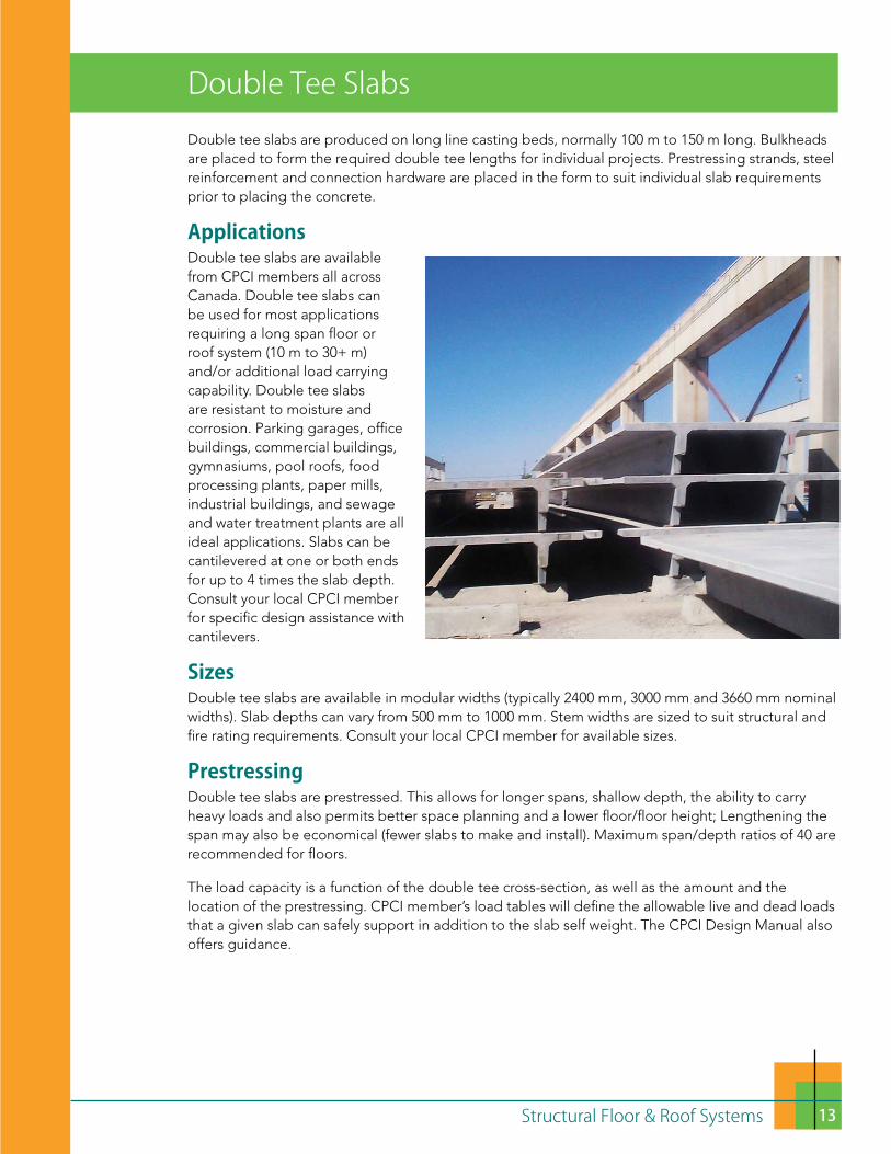
Double tee slabs are produced on long line casting beds, normally 100 m to 150 m long. Bulkheads are placed to form the required double tee lengths for individual projects. Prestressing strands, steel reinforcement and connection hardware are placed in the form to suit individual slab requirements prior to placing the concrete.
ApplicationsDouble tee slabs are available from CPCI members all across Canada. Double tee slabs can be used for most applications requiring a long span floor or roof system (10 m to 30+ m) and/or additional load carrying capability. Double tee slabs are resistant to moisture and corrosion. Parking garages, office buildings, commercial buildings, gymnasiums, pool roofs, food processing plants, paper mills, industrial buildings, and sewage and water treatment plants are all ideal applications. Slabs can be cantilevered at one or both ends for up to 4 times the slab depth. Consult your local CPCI member for specific design assistance with cantilevers.
SizesDouble tee slabs are available in modular widths (typically 2400 mm, 3000 mm and 3660 mm nominal widths). Slab depths can vary from 500 mm to 1000 mm. Stem widths are sized to suit structural and fire rating requirements. Consult your local CPCI member for available sizes.
PrestressingDouble tee slabs are prestressed. This allows for longer spans, shallow depth, the ability to carry heavy loads and also permits better space planning and a lower floor/floor height; Lengthening the span may also be economical (fewer slabs to make and install). Maximum span/depth ratios of 40 are recommended for floors.
The load capacity is a function of the double tee cross-section, as well as the amount and the location of the prestressing. CPCI member’s load tables will define the allowable live and dead loads that a given slab can safely support in addition to the slab self weight. The CPCI Design Manual also offers guidance.
Double Tee Slabs

14 Structural Floor & Roof Systems
Finished CeilingDouble tee slabs, cast on smooth steel forms, have a finished underside. The smooth ceiling provided by a double tee slab may require only the caulking of the longitudinal joints. The underside of slabs can be specified either as Commercial, Standard Grade, Finish Grade B or Finish Grade A as described in CSA A23.4 Precast Concrete–Materials and Construction.
Metal panels attached to the bottoms of the stems create ducts. Diffuser panels provide a flush ceiling.
Bearing Supports for Double Tee SlabsDouble tee slabs can be supported on many types of supports designed to carry the required dead and live loads. Precast beams, precast walls, cast-in-place concrete beams and walls, masonry walls, insulated concrete forming system walls and structural steel beams are all suitable for use with double tee slabs as load bearing systems—consult your local CPCI member for details.
Superimposed Loads 3.60 kPa 4.80 kPa 6.00 kPa
800 DT x 2400 x 50 F 25 m 23 m 22 m
800 DT x 3660 x 100 F 21 m 19.5 m 18.5 m
* Consult your local CPCI member for the sizes/capacities in your area.
Maximum Spans for Various 800 mm Double Tees

15Structural Floor & Roof Systems
Metal panels attached to the bottoms of the stems create ducts. Diffuser panels provide a flush ceiling.
Typical Double Tee DetailNote: Double Tees may or may not receive a field applied topping. Contact your local CPCI member for further details.
The minimum recommended bearing width is 150 mm. Double tee slabs in double bearing on a single support beam or wall will require at least a 300 mm wide bearing surface.
Holes and OpeningsFlange openings larger than 200mm should preferably be formed at the precast plant. These may also be sawn at the job site upon direction by the manufacturers engineer. Large openings to accommodate mechanical ducts and skylights can be accommodated per the sealed and signed working approved shop drawings without cutting any portion of the double tee stem. Openings through double tee stems can be provided for piping and electrical conduits. These openings should be kept to a minimum and located at the top of the stem (underside of the flange).
Load DistributionDouble tee slabs are designed as individual, one way, simple span slabs. When the slabs are installed and welded together at the flange edges, the connected individual slabs become a system that can behave similarly to a monolithic slab to transfer forces from one slab to another (particularly in floor applications where a cast-in-place topping is placed over the double tee slabs). In most double tee slab applications, non-uniform loading occurs in the form of line loads, concentrated loads, or load concentrations at openings. The ability of individual slabs to interact allows these load concentrations to be shared by adjacent slabs.
DiaphragmsA series of double tee slabs can resist lateral loads in the form of a welded slab assembly, provided proper connections and details are installed. The function of a diaphragm is to transmit wind loads, seismic loads and lateral earth pressures from the building elements to lateral force-resisting elements such as shear walls that carry the loads to the foundations.
50 mm

16 Structural Floor & Roof Systems
Top Surface PreparationUntopped double tee slabs are generally used for roof applications and some parking garage floors. The top surface of untopped double tee slabs is screeded off and finished with a wood float during production to provide a uniform but slip resistant finish.
Double tee floor slabs in buildings may require a 50 mm to 75 mm cast-in- place topping depending on the floor loading and the number and size of embedded conduit to be installed. The top surface of double tee slabs receiving concrete topping is rough broomed to allow bonding of the topping to the double tees. Structural toppings are often used in high seismic zones and where heavy loadings are to be supported.
Fire ResistanceDouble tee slabs provide excellent fire resistance. Depending on slab thickness and strand cover, fire ratings of 1 to 2 hour endurance can be readily achieved. The fire rating is dependent on equivalent thickness for heat transmission, concrete cover to the prestressing strands for strength and end restraint. The NBCC and provincial building codes specify the required fire ratings.
Sound TransmissionDouble tee slab concrete floor-ceiling assemblies have excellent sound transmission characteristics. Sound Transmission Class (STC) ratings for double tees are approximately 54 with topping. The Impact Insulation Class (IIC) ratings start at about 24 for a plain topped slab and can be increased to over 70 with the addition of resilient materials such as under padding and carpeting.

17Structural Floor & Roof Systems
General Requirements Hollow Core Slabs and Double Tee Slabs
Design ResponsibilitiesIt is customary for CPCI members to perform the final engineering for double tee and hollow core slabs supplied to a project. This can include design for vertical loads and lateral loads specified by the Engineer of Record, and embedded items for specified connection forces and handling, shipping and erection loads.
The Engineer of Record plays a very important role in the design process. Enough preliminary planning should be done in advance to ensure that the specified floor and roof system is achievable. The project should be engineered in enough detail to avoid requiring changes from the contract documents.
The contract documents must clearly indicate design criteria for double tee and hollow core slabs. This is especially important when the precast slabs must interface with other construction materials. The forces to be transmitted through connections must be specified in the contract documents. CPCI members are best able to determine the most efficient types of connection elements to be embedded in a slab. However, the balance of connections that interface with other materials should be detailed in the contract documents, with input from local CPCI members.
The Engineer of Record also has a responsibility in the review and approval of erection drawings prepared by the precast producer. Review of these drawings is the last opportunity to ensure that the precaster’s understanding of the project coincides with the intent of a design. Erection drawings should be checked for proper design loads, proper details and bearing conditions, conformance with specified fire ratings, and the location of openings.
Code/Quality RequirementsDouble tee and hollow core slabs supplied by CPCI members meet or exceed the requirements of the National Building Code of Canada, and are designed, constructed and installed in accordance with CSA A23.3 Design of Concrete Structures, CSA A23.4 Precast Concrete–Materials and Construction and

18 Structural Floor & Roof Systems
CSA S413 Parking Structures. Precast concrete plant cast products supplied by CPCI members are CPCI Certified in accordance with CSA Standard A23.4 and the United States PCI MNL-116.
CamberMost hollow core slabs and double tee slabs have camber—an upward deflection produced by the effects of the prestressing. Consideration should be given to the effects of differential camber in the planning stages of a project. Joints between slabs of unequal spans or joints at which a change in the span direction occurs will have differential camber. This must be recognized and dealt with in the design layout. Walls may be located to hide some of these joints. Actual cambers will vary from the calculated values due to the many variables that affect camber. Calculated camber values should be considered estimated values, suitable for preliminary planning purposes.
Camber must also be accommodated when a topping is provided. The quantity of topping required must consider the amount of camber and the function of the floor. In occupancies where flat floors are not a requirement, a constant topping thickness may be used to follow the curvature of the slab. At the other extreme, if a “flat floor” is required in a structure consisting of multiple bays of varying length slabs and changes in slab direction, the highest point will determine the top elevation of the topping. A greater amount of topping will then be required in “low areas”.
When a composite bonded concrete structural topping is required, the thickness specified on the drawings is the minimum topping thickness required at the mid-span of the slabs, not at the supports. For example, a 50 mm composite concrete topping should have a minimum of 50 mm of topping placed at the mid-span of the slabs, with more than 50 mm being placed near the ends (for slabs with a camber).
Camber, camber growth, and deflections must also be taken into account in roofing details. In applications that require drainage, slopes should be large enough to overcome expected camber. Where changes in relative slab position can occur, counter flashings are suggested to accommodate these changes.
ConnectionsGenerally, all precast to precast connections are designed and supplied by the precast manufacturer. The connections between the precast components and other building

19Structural Floor & Roof Systems
systems are generally designed and detailed by the Engineer of Record, with input from the precast supplier, prior to finalizing the project documents. In some cases, the precast supplier may be required to design and supply the connection hardware embedded into cast-in-place concrete on-site by the general contractor, and into the precast components at the precast plant.
Speed of ConstructionFast construction means earlier project completion and the resulting cost savings. Double tee and hollow core
slabs can help to speed up construction schedules. Manufacturing of the slabs can proceed in a CPCI member’s high efficiency plant while site construction is underway. Slabs can be delivered to the jobsite and installed to meet the client’s schedule regardless of weather conditions.
An installed double tee or hollow core deck provides a working platform for other trades. The combination of double tees or hollow core slabs with a structural precast concrete frame and/or precast concrete bearing walls will speed construction even more. The entire building shell can be supplied and installed under a single precast concrete contract.
ErectionCPCI members typically have their own crews available to install double tee and hollow core slabs. Services are also available to cut holes and openings up to 150 mm diameter for mechanical trades. Openings larger than 150 mm should be located on the shop drawings at the time of approval.
Design Stage Assistance AvailableCPCI members who manufacture hollow core, double tee slabs and building systems are available to provide technical assistance (load tables, typical details, etc.) and budget pricing at the preliminary design stage for your next project.

20 Structural Floor & Roof Systems
CPCI Members
Institute:The Canadian Precast/Prestressed Concrete Institute (CPCI) is a nonprofit corporation founded in 1961 for the purpose of advancing the design, manufacture and use of structural, architectural and specialty precast prestressed concrete in Canada.
• CPCI is unique—it is an association of manufacturers, trades and design professionals with a representative mix of companies and individuals.
• Membership includes precast producers (Active Members), industry suppliers (Associate and Supporting Members), engineers and architects (Professional Firm and Professional Individual Members), plus affiliate and student members.
• These members receive technical information from CPCI and PCI (USA).
• Consult the CPCI website (www.cpci.ca) for more information and application forms.
Technology:CPCI members are committed to developing innovative solutions to meet the demands of the construction industry. CPCI is a source for knowledge, statistics, ideas and information relating to the design, manufacture, and use of precast prestressed concrete. Through investigations and research, new engineering processes are established to ensure quality and new product design. CPCI’s aim is to improve the efficiency and effectiveness of the industry as a whole.
CPCI Members:CPCI member companies are precast professionals capable and willing to help you successfully complete your next project. Involve your CPCI partner at the early stages of project planning. Whether the challenges are structural, aesthetic, timing or economic, CPCI members can provide invaluable input. You will find CPCI members are dedicated, committed and competent to contribute to the realization of the standards you have set for your projects. They will be there to advise and assist you from concept to completion. Consult the CPCI website: www.cpci.ca for members near you.

21Structural Floor & Roof Systems
CPCI Guide SpecificationsDownload these specifications at: www.cpci.ca — click on: Specifications
• Section 03 41 13 – Precast Concrete Hollowcore Planks• Section 03 41 00 – Structural Precast Concrete• Section 03 45 00 – Architectural Precast Concrete
These online specifications are updated to reflect changes in codes, standards and industry practices.
Detailed Design Information:CPCI Design ManualThe CPCI Design Manual contains comprehensive design and construction information in accordance with industry practice and Canadian design and construction codes and standards. Order from: www.cpci.ca
CPCI Resource Material & CPCI Technical SupportCPCI Resource Materials are created to assist design and construction professionals to understand precast prestressed concrete products and systems. The material is free-of-charge and downloadable through www.cpci.ca (Resources).
CPCI Technical Help Desk Services are designed to provide additional technical information and support about the use of precast and prestressed concrete products. Please email us at [email protected] or call us at 1. 877. 937. 2724
CPCI Members Near You and Your ProjectTo contact CPCI members go to: www.precastcertification.ca
Other CPCI Resources• CPCI Projects of the Month• CPCI Insulated Precast Wall Panel Technical Guide• CPCI Infrastructure Solutions Technical Guide• CPCI Infrastructure for Life Publication• CPCI Architectural Precast Concrete Technical Guide• CPCI Structural Solutions Technical Guide• CPCI Colour and Texture Selection Guide• CPCI Research such as the Life Cycle Assessment Study and
the Hollowcore Shear Capacity Research from the University of Manitoba.
Other PCI Resources www.pci.org• PCI Hollowcore Design Manual. • PCI Parking Structures Design and Construction Manual. • Peer-reviewed technical papers as published in the PCI
JOURNAL.
CPCI Resources

22 Structural Floor & Roof Systems
How Precast Certification is a Requirement of the National Building Code of CanadaNational Building Code of Canada (2010) – Division B:Clause 4.3.3.1.(1) – Buildings and their structural members made of plain, reinforced and prestressed concrete shall conform to CSA A23.3, Design of Concrete Structures.
Clause A-4.3.3.1.(1) – Precast Concrete- CSA A23.3, Design of Concrete Structures, requires precast concrete members to conform to CAN/CSA-A23.4, Precast Concrete – Materials and Construction.
CSA A23.3 – Design of concrete structures: CSA A23.3-14 – Clause 16.2.1 – All precast concrete elements covered by this standard shall be manufactured and erected in accordance with CSA A23.4.
CSA A23.4 – Precast concrete – Materials and construction:CSA A23.4-16 – Clause 4.2 – Precast concrete elements produced and installed in accordance with this Standard shall be produced by prequalified manufacturers.
It is not a requirement of the National Building Code, Provincial Building Codes or CSA Standards that products and systems are required to be certified by CSA, only in accordance with CSA Standards.
CPCI Precast Concrete Certification Program for Structural, Architectural and Specialty Precast Concrete Products and SystemsThe CPCI certification program is designed to qualify manufacturers who fabricate structural, architectural and specialty precast concrete.
Manufacturers must meet the requirements of CSA Standard A23.4, including Annexes A and B, together with PCI MNL-116 and 117 and CPCI certification requirements.
Manufacturers are evaluated on their quality system, documentation, production procedures, management, engineering, personnel, equipment, finished products and assemblies. Independent professional engineers conduct two-day audits twice annually.
Certification confirms a manufacturer’s capability to produce quality products and systems.
The CPCI Certification Program assures project specifiers and owners of a Manufacturer’s comprehensive in-house quality assurance program and acceptable production methods.
PurposeThe purpose of the audit program is to provide owners and designers with manufacturers who are:
• Qualified to manufacture the products they supply to the marketplace• Competent to provide quality precast with adequate personnel and facilities• Committed to improving the quality of their products and systems
Quality Audits are the heart of the precast certification program• Audits ensure manufacturers have a quality system in place that is consistently adhered to• Audits ensure adherence to national standards• Audits ensure adherence to requirements of the precast certification program• Audits evaluate and identify areas requiring upgrading or corrective action (continual improvement)
CPCI Certification

23Structural Floor & Roof Systems
PROGRAMME NORD-AMÉRICAIN D’USINE DE BÉTONPRÉFABRIQUE EN DÉVELOPPEMENT DURABLE
Precast Concrete and the Environment
Developed in Canada in 2012 the North American Precast Concrete Sustainable Plant Program (NAPCSPP) is a program designed to encourage continuous improvement and compliance to environmental and sustainability regulations and standards. Environmental performance is determined based on the intents of all applicable government environmental policies. Sustainability performance builds on the North American Precast Concrete LCA research already completed by the North American Precast Concrete Industry. The program is not intended to replace municipal, provincial/state or federal environmental acts and their requirements; it is a program designed to track the improvements implemented by each manufacturer. It is the responsibility of each individual manufacturer to understand and comply with the applicable government requirements.
As part of this program, facilities are required to submit confidential benchmark reports on a quarterly basis. The aggregated results of the program are communicated to the public in Canada through the CPCI Sustainable Plant Program quarterly reports.
For more info: www.sustainableprecast.ca
Precast Concrete EPD’S Environmental Product Declarations (EPDs) are third party verified (certified) reports published by product manufacturers that provide quality assured and comparable information regarding environmental performance of their products or system.
With the proliferation of eco-labels and green certifications worldwide, it can be confusing determining a product’s environmental attributes. Well established in other parts of the world, EPDs are starting to appear in North America as the common methodology for assessing the potential environmental performance of a product or process. The CaGBC LEED v4 Rating System and Architecture 2030 are starting to demand EPDs for products.
Members of the Canadian Precast/ Prestressed Concrete Institute (CPCI), the National Precast Concrete Association (NPCA) and the Precast/Prestressed Concrete Institute (PCI) are the first concrete manufacturers in North America to achieve a third-party verified EPD, providing comprehensive, uniform details about a product’s composition and environmental impact throughout its lifecycle.These North American Precast Concrete associations worked together with ASTM International and the Athena Sustainable Materials Institute towards this development.
For more information on Precast Concrete EPD’S: www.sustainableprecast.ca

Canadian Precast/Prestressed Concrete InstitutePO Box 24058 Hazeldean, Ottawa, Ontario, Canada K2M 2C3Telephone (613) 232-2619 Fax: (613) 232-5139Toll Free: 1-877-YES-CPCI (1-877-937-2724)E-mail: [email protected]
www.cpci.ca