structural performance of aluminum and stainless … · †orau/orise maryland, 4692 millennium...
TRANSCRIPT
Structural Performance of Aluminum and Stainless Steel
Pyramidal Truss Core Sandwich Panels
by Kevin J. Doherty, Aristedes Yiournas, Jordan A. Wagner, and
Yellapu Murty
ARL-TR-4867 July 2009
Approved for public release; distribution is unlimited.
NOTICES
Disclaimers The findings in this report are not to be construed as an official Department of the Army position unless so designated by other authorized documents. Citation of manufacturer’s or trade names does not constitute an official endorsement or approval of the use thereof. Destroy this report when it is no longer needed. Do not return it to the originator.
Army Research Laboratory Aberdeen Proving Ground, MD 21005-5069
ARL-TR-4867 July 2009
Structural Performance of Aluminum and Stainless Steel Pyramidal Truss Core Sandwich Panels
Kevin J. Doherty
Weapons and Materials Research Directorate, ARL
Aristedes Yiournas Dynamic Science, Inc.
Jordan A. Wagner
Oak Ridge Institute for Science and Education
Yellapu Murty Cellular Materials International, Inc.
Approved for public release; distribution is unlimited.
ii
REPORT DOCUMENTATION PAGE Form Approved OMB No. 0704-0188
Public reporting burden for this collection of information is estimated to average 1 hour per response, including the time for reviewing instructions, searching existing data sources, gathering and maintaining the data needed, and completing and reviewing the collection information. Send comments regarding this burden estimate or any other aspect of this collection of information, including suggestions for reducing the burden, to Department of Defense, Washington Headquarters Services, Directorate for Information Operations and Reports (0704-0188), 1215 Jefferson Davis Highway, Suite 1204, Arlington, VA 22202-4302. Respondents should be aware that notwithstanding any other provision of law, no person shall be subject to any penalty for failing to comply with a collection of information if it does not display a currently valid OMB control number. PLEASE DO NOT RETURN YOUR FORM TO THE ABOVE ADDRESS.
1. REPORT DATE (DD-MM-YYYY)
July 2009 2. REPORT TYPE
Final 3. DATES COVERED (From - To)
August 2006–October 2008 4. TITLE AND SUBTITLE
Structural Performance of Aluminum and Stainless Steel Pyramidal Truss Core Sandwich Panels
5a. CONTRACT NUMBER
5b. GRANT NUMBER
5c. PROGRAM ELEMENT NUMBER
6. AUTHOR(S)
Kevin J. Doherty, Aristedes Yiournas,* Jordan A. Wagner,† and Yellapu Murty‡ 5d. PROJECT NUMBER
622105.AH84 5e. TASK NUMBER
5f. WORK UNIT NUMBER
7. PERFORMING ORGANIZATION NAME(S) AND ADDRESS(ES)
U.S. Army Research Laboratory ATTN: RDRL-WMM-D Aberdeen Proving Ground, MD 21005-5069
8. PERFORMING ORGANIZATION REPORT NUMBER
ARL-TR-4867
9. SPONSORING/MONITORING AGENCY NAME(S) AND ADDRESS(ES)
10. SPONSOR/MONITOR’S ACRONYM(S)
11. SPONSOR/MONITOR'S REPORT NUMBER(S)
12. DISTRIBUTION/AVAILABILITY STATEMENT
Approved for public release; distribution is unlimited. 13. SUPPLEMENTARY NOTES *Dynamic Science, Inc., Defense Technical Services Division, Aberdeen, MD 21001 †ORAU/ORISE Maryland, 4692 Millennium Dr., Ste. 101, Belcamp, MD 21017 ‡Cellular Materials International, Inc., 2 Boar’s Head Lane, Charlottesville, VA 22903
14. ABSTRACT
Future lightweight military vehicles will demand increasingly mass-efficient structures to satisfy design requirements such as increased mobility and survivability. One possible family of lightweight structures entails sandwich panels consisting of solid facesheets and a low-density core. The sandwich structures can provide both structural strength and stiffness, with load-bearing potential. In this study, sandwich panels consisting of metallic facesheets and a pyramidal truss core manufactured from either 6061-T6 aluminum or 316L stainless steel are investigated. The structures were subjected to panel bending and in-plane compression testing to explore the effects of relative core density and process parameters. The mechanical response and failure mechanisms were categorized for the different structures and materials. The processing challenges associated with fabricating larger panels are also discussed. 15. SUBJECT TERMS
truss core, sandwich panels, mechanical properties, aluminum, stainless steel
16. SECURITY CLASSIFICATION OF: 17. LIMITATION OF ABSTRACT
UU
18. NUMBER OF PAGES
22
19a. NAME OF RESPONSIBLE PERSON
Kevin J. Doherty a. REPORT
Unclassified b. ABSTRACT
Unclassified c. THIS PAGE
Unclassified 19b. TELEPHONE NUMBER (Include area code)
410-306-0871 Standard Form 298 (Rev. 8/98)
Prescribed by ANSI Std. Z39.18
iii
Contents
List of Figures iv
List of Tables v
Acknowledgments vi
1. Introduction 1
2. Experimental Procedures 2
3. Results 5
4. Discussion 10
5. Summary 11
6. References 12
Distribution List 13
iv
List of Figures
Figure 1. Manufacturing route for aluminum pyramidal core sandwich panels. ............................2
Figure 2. Manufacturing route for stainless steel pyramidal core sandwich panels. ......................3
Figure 3. Double-bend (left) and single-bend (right) pyramidal core architectures. .....................3
Figure 4. Examples of three-point bend testing of pyramidal truss core beams without (left) and with (right) an aluminum distribution plate. .......................................................................4
Figure 5. Example of in-plane compression testing. .......................................................................5
Figure 6. Measured bending rigidity [(EI)eq/b] (left) and specific bending rigidity (right) for single-bend pyramidal core sandwich beams. ...........................................................................6
Figure 7. Examples of beam failures for single-bend pyramidal core sandwich panels. ................7
Figure 8. Measured bending rigidity [(EI)eq/b] (left) and specific bending rigidity (right) for double-bend pyramidal core sandwich beams. ..........................................................................7
Figure 9. Examples of beam failures for double-bend pyramidal core sandwich panels. ..............8
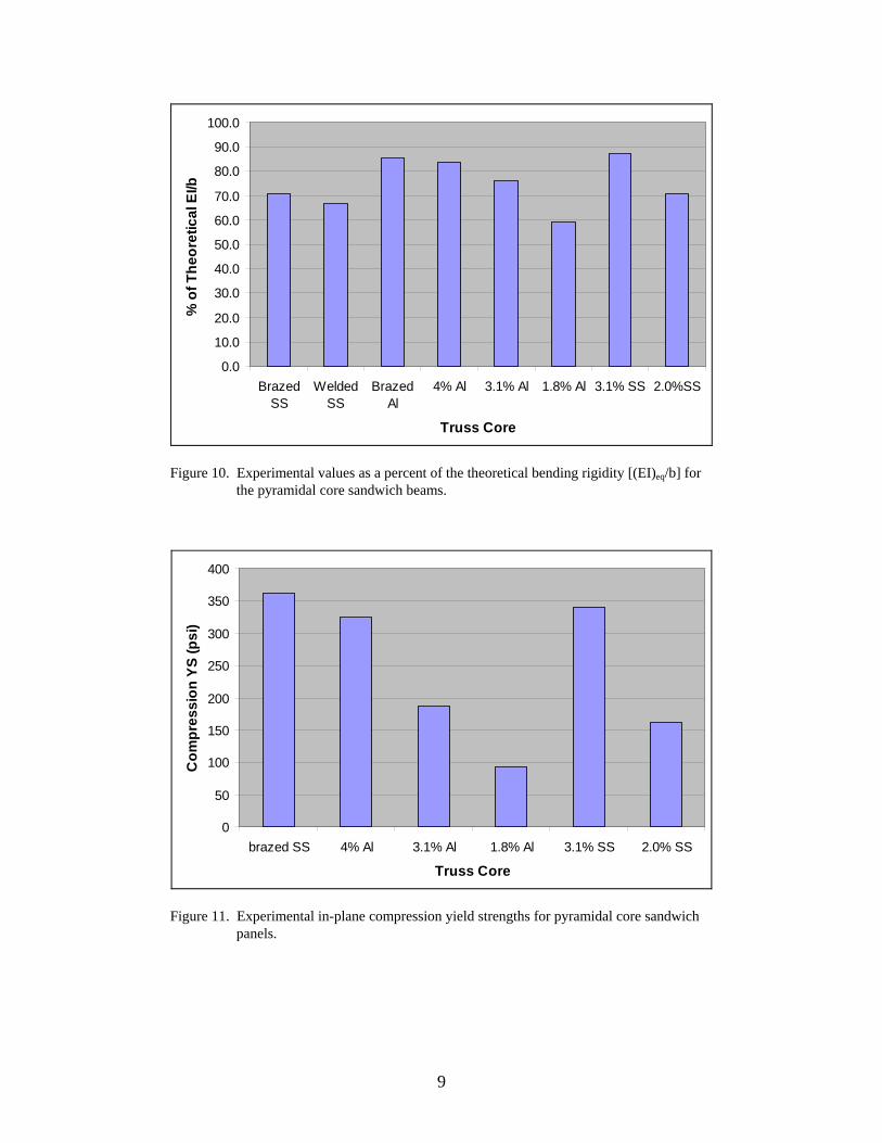
Figure 10. Experimental values as a percent of the theoretical bending rigidity [(EI)eq/b] for the pyramidal core sandwich beams. .........................................................................................9
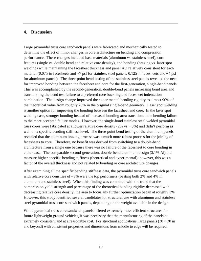
Figure 11. Experimental in-plane compression yield strengths for pyramidal core sandwich panels. ........................................................................................................................................9
v
List of Tables
Table 1. Pyramidal truss core panels tested. ...................................................................................4
Table 2. Theoretical bending rigidity [(EI)eq/b] of monolithic and single-bend pyramidal cores. ..........................................................................................................................................6
Table 3. Theoretical bending rigidity [(EI)eq/b] of double-bend pyramidal core sandwich panels. ........................................................................................................................................7
vi
Acknowledgments
The research in this report was supported in part by an appointment to the Research Participation Program at the U.S. Army Research Laboratory (ARL) administered by the Oak Ridge Institute for Science and Education through an interagency agreement between the U.S. Department of Energy and ARL.
1
1. Introduction
Future lightweight ground vehicles will demand increasingly mass-efficient structures to satisfy design requirements such as increased mobility and survivability. Historically, ground vehicles provide protection via monolithic metallic plates, which are not weight efficient. By replacing these heavy plates with multifunctional lightweight sandwich panels, improvements in specific strength, structural stiffness, and overall survivability can be achieved. In addition, reducing the weight of military vehicles provides benefits, including increased range, maneuverability, fuel efficiency, and speed. While low-density sandwich panels hold significant promise for future ground vehicles, the ability to adequately join facesheets with a low-density core is important to the integration of sandwich structures into multifunctional systems (1).
It is well known that sandwich plates, using strong and stiff facesheets with a low-density core, possess a superior bending stiffness and strength to monolithic beams of the same mass under quasi-static loading. However, core architecture can be generalized into two distinct groups governed by their deformation mechanism. While most cellular solids are bending dominated structures (such as open-cell foams), stretch dominated structures (such as pyramidal core trusses) are more efficient for structural applications (2). Therefore, pyramidal core structures offer a variety of design parameters, which can be tailored to satisfy multifunctional needs that span from lightweight structure to energy absorption with controlled deformation.
Methods for manufacturing sandwich panels with periodic cores have been described (3, 4). Initial efforts utilized investment casting of high-fluidity, nonferrous casting alloys (5–9). However, the extreme difficulty of fabricating defect-free cast structures with the inherent lack of mechanical robustness of the cast material led to a push for the development of using perforated wrought metal sheets. These folded cores can be bonded to facesheets by a variety of joining methods, including brazing and laser spot welding. Typically, austenitic stainless steel (10–11) and age-hardenable aluminum alloys (12) have been used to fabricate truss geometries. These materials are chosen more for their ease of fabrication than their enhanced mechanical properties; however, robust and efficient structures are regularly produced in both systems. While stronger metallic materials could create enhanced truss structures, the difficulty associated with the manufacturing would be greatly increased.
The focus of this work is to examine the mechanical response and failure mechanisms of sandwich panels consisting of metallic facesheets and a pyramidal truss core manufactured from wrought aluminum (Al) and stainless steel (SS). The structures are subjected to panel bending and in-plane compression testing to explore the effects of base materials, relative core density, and process parameters. The processing challenges associated with fabricating larger panels are also discussed.
2
2. Experimental Procedures
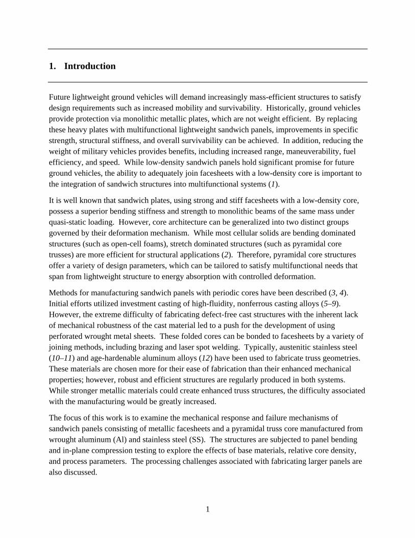
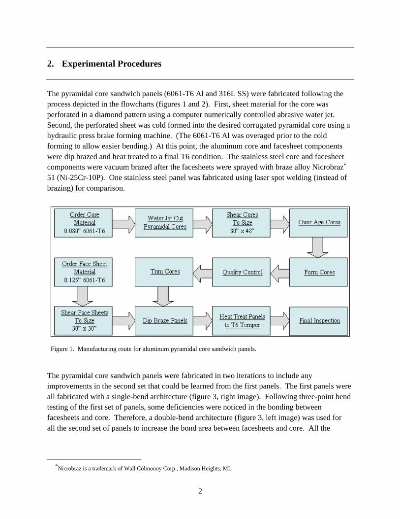
The pyramidal core sandwich panels (6061-T6 Al and 316L SS) were fabricated following the process depicted in the flowcharts (figures 1 and 2). First, sheet material for the core was perforated in a diamond pattern using a computer numerically controlled abrasive water jet. Second, the perforated sheet was cold formed into the desired corrugated pyramidal core using a hydraulic press brake forming machine. (The 6061-T6 Al was overaged prior to the cold forming to allow easier bending.) At this point, the aluminum core and facesheet components were dip brazed and heat treated to a final T6 condition. The stainless steel core and facesheet components were vacuum brazed after the facesheets were sprayed with braze alloy Nicrobraz* 51 (Ni-25Cr-10P). One stainless steel panel was fabricated using laser spot welding (instead of brazing) for comparison.
Figure 1. Manufacturing route for aluminum pyramidal core sandwich panels.
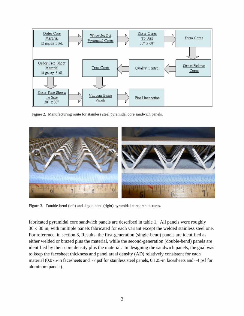
The pyramidal core sandwich panels were fabricated in two iterations to include any improvements in the second set that could be learned from the first panels. The first panels were all fabricated with a single-bend architecture (figure 3, right image). Following three-point bend testing of the first set of panels, some deficiencies were noticed in the bonding between facesheets and core. Therefore, a double-bend architecture (figure 3, left image) was used for all the second set of panels to increase the bond area between facesheets and core. All the
*Nicrobraz is a trademark of Wall Colmonoy Corp., Madison Heights, MI.
3
Figure 2. Manufacturing route for stainless steel pyramidal core sandwich panels.
Figure 3. Double-bend (left) and single-bend (right) pyramidal core architectures.
fabricated pyramidal core sandwich panels are described in table 1. All panels were roughly 30 30 in, with multiple panels fabricated for each variant except the welded stainless steel one. For reference, in section 3, Results, the first-generation (single-bend) panels are identified as either welded or brazed plus the material, while the second-generation (double-bend) panels are identified by their core density plus the material. In designing the sandwich panels, the goal was to keep the facesheet thickness and panel areal density (AD) relatively consistent for each material (0.075-in facesheets and ~7 psf for stainless steel panels, 0.125-in facesheets and ~4 psf for aluminum panels).
4
Table 1. Pyramidal truss core panels tested.
Material
Facesheet Thickness
(in)
Core
Height (in)
Core Relative Density
(%)
Bend
Joining Method
316L 0.075 0.75 3.0 Single Braze 316L 0.075 0.9 2.0 Single Weld 316L 0.075 1.1 2.0 Double Braze 316L 0.075 1.14 3.1 Double Braze
6061-T6 0.125 0.95 3.3 Single Braze 6061-T6 0.125 0.95 4.0 Double Braze 6061-T6 0.125 1.06 1.7 Double Braze 6061-T6 0.125 1.17 3.1 Double Braze
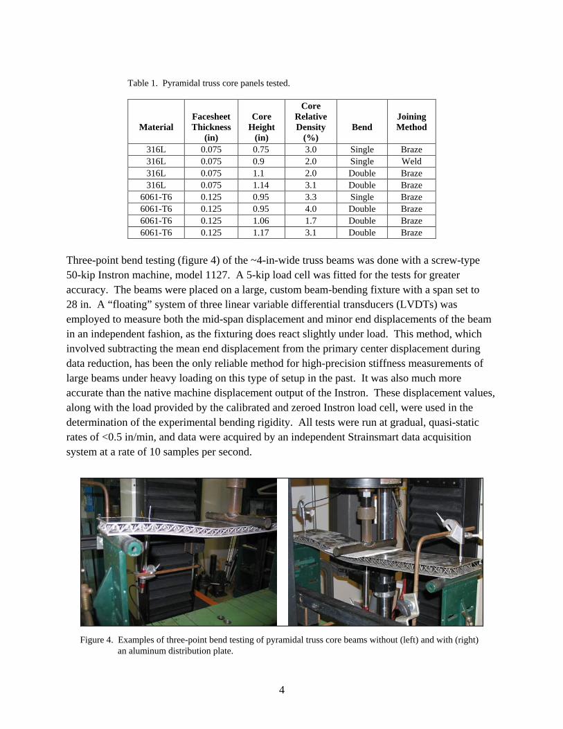
Three-point bend testing (figure 4) of the ~4-in-wide truss beams was done with a screw-type 50-kip Instron machine, model 1127. A 5-kip load cell was fitted for the tests for greater accuracy. The beams were placed on a large, custom beam-bending fixture with a span set to 28 in. A “floating” system of three linear variable differential transducers (LVDTs) was employed to measure both the mid-span displacement and minor end displacements of the beam in an independent fashion, as the fixturing does react slightly under load. This method, which involved subtracting the mean end displacement from the primary center displacement during data reduction, has been the only reliable method for high-precision stiffness measurements of large beams under heavy loading on this type of setup in the past. It was also much more accurate than the native machine displacement output of the Instron. These displacement values, along with the load provided by the calibrated and zeroed Instron load cell, were used in the determination of the experimental bending rigidity. All tests were run at gradual, quasi-static rates of <0.5 in/min, and data were acquired by an independent Strainsmart data acquisition system at a rate of 10 samples per second.
Figure 4. Examples of three-point bend testing of pyramidal truss core beams without (left) and with (right) an aluminum distribution plate.
5
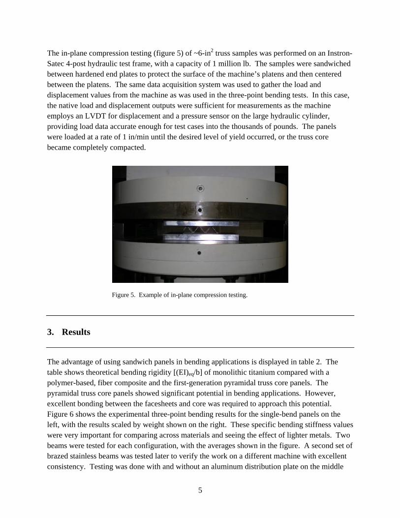
The in-plane compression testing (figure 5) of ~6-in2 truss samples was performed on an Instron-Satec 4-post hydraulic test frame, with a capacity of 1 million lb. The samples were sandwiched between hardened end plates to protect the surface of the machine’s platens and then centered between the platens. The same data acquisition system was used to gather the load and displacement values from the machine as was used in the three-point bending tests. In this case, the native load and displacement outputs were sufficient for measurements as the machine employs an LVDT for displacement and a pressure sensor on the large hydraulic cylinder, providing load data accurate enough for test cases into the thousands of pounds. The panels were loaded at a rate of 1 in/min until the desired level of yield occurred, or the truss core became completely compacted.
Figure 5. Example of in-plane compression testing.
3. Results
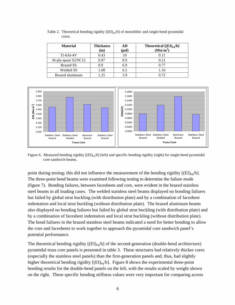
The advantage of using sandwich panels in bending applications is displayed in table 2. The table shows theoretical bending rigidity [(EI)eq/b] of monolithic titanium compared with a polymer-based, fiber composite and the first-generation pyramidal truss core panels. The pyramidal truss core panels showed significant potential in bending applications. However, excellent bonding between the facesheets and core was required to approach this potential. Figure 6 shows the experimental three-point bending results for the single-bend panels on the left, with the results scaled by weight shown on the right. These specific bending stiffness values were very important for comparing across materials and seeing the effect of lighter metals. Two beams were tested for each configuration, with the averages shown in the figure. A second set of brazed stainless beams was tested later to verify the work on a different machine with excellent consistency. Testing was done with and without an aluminum distribution plate on the middle
6
Table 2. Theoretical bending rigidity [(EI)eq/b] of monolithic and single-bend pyramidal cores.
Material Thickness (in)
AD (psf)
Theoretical [(EI)eq/b] (Msi-in3)
Ti-6Al-4V 0.43 10 0.11 36 ply-quasi S2/SC15 0.97 8.9 0.21
Brazed SS 0.9 6.9 0.77 Welded SS 1.08 6.5 1.16
Brazed aluminum 1.25 3.9 0.72
0.000
0.100
0.200
0.300
0.400
0.500
0.600
0.700
0.800
0.900
Stainless SteelBrazed
Stainless SteelWelded
AluminumBrazed
Stainless SteelBrazed
Truss Core
EI/b
(M
si-
in3 )
0.0000
0.0200
0.0400
0.0600
0.0800
0.1000
0.1200
0.1400
0.1600
0.1800
Stainless SteelBrazed
Stainless SteelWelded
AluminumBrazed
Stainless SteelBrazed
Truss Core
EI/b
(AD
)
Figure 6. Measured bending rigidity [(EI)eq/b] (left) and specific bending rigidity (right) for single-bend pyramidal core sandwich beams.
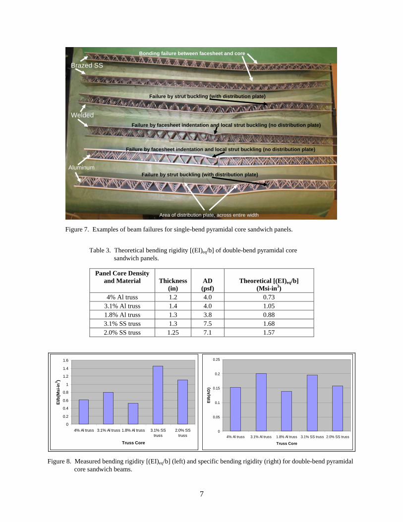
point during testing; this did not influence the measurement of the bending rigidity [(EI)eq/b]. The three-point bend beams were examined following testing to determine the failure mode (figure 7). Bonding failures, between facesheets and core, were evident in the brazed stainless steel beams in all loading cases. The welded stainless steel beams displayed no bonding failures but failed by global strut buckling (with distribution plate) and by a combination of facesheet indentation and local strut buckling (without distribution plate). The brazed aluminum beams also displayed no bonding failures but failed by global strut buckling (with distribution plate) and by a combination of facesheet indentation and local strut buckling (without distribution plate). The bond failures in the brazed stainless steel beams indicated a need for better bonding to allow the core and facesheets to work together to approach the pyramidal core sandwich panel’s potential performance.
The theoretical bending rigidity [(EI)eq/b] of the second-generation (double-bend architecture) pyramidal truss core panels is presented in table 3. These structures had relatively thicker cores (especially the stainless steel panels) than the first-generation panels and, thus, had slightly higher theoretical bending rigidity [(EI)eq/b]. Figure 8 shows the experimental three-point bending results for the double-bend panels on the left, with the results scaled by weight shown on the right. These specific bending stiffness values were very important for comparing across
7
Brazed SS
Welded
Bonding failure between facesheet and core
Failure by strut buckling (with distribution plate)
Failure by facesheet indentation and local strut buckling (no distribution plate)
Aluminum
Area of distribution plate, across entire width
Failure by facesheet indentation and local strut buckling (no distribution plate)
Failure by strut buckling (with distribution plate)
Figure 7. Examples of beam failures for single-bend pyramidal core sandwich panels.
Table 3. Theoretical bending rigidity [(EI)eq/b] of double-bend pyramidal core
sandwich panels.
Panel Core Density and Material
Thickness
(in)
AD (psf)
Theoretical [(EI)eq/b]
(Msi-in3) 4% Al truss 1.2 4.0 0.73
3.1% Al truss 1.4 4.0 1.05 1.8% Al truss 1.3 3.8 0.88 3.1% SS truss 1.3 7.5 1.68 2.0% SS truss 1.25 7.1 1.57
0
0.2
0.4
0.6
0.8
1
1.2
1.4
1.6
4% Al truss 3.1% Al truss 1.8% Al truss 3.1% SStruss
2.0% SStruss
Truss Core
EI/b
(Ms
i-in
3 )
0
0.05
0.1
0.15
0.2
0.25
4% Al truss 3.1% Al truss 1.8% Al truss 3.1% SS truss 2.0% SS truss
Truss Core
EI/b
(AD
)
Figure 8. Measured bending rigidity [(EI)eq/b] (left) and specific bending rigidity (right) for double-bend pyramidal core sandwich beams.
8
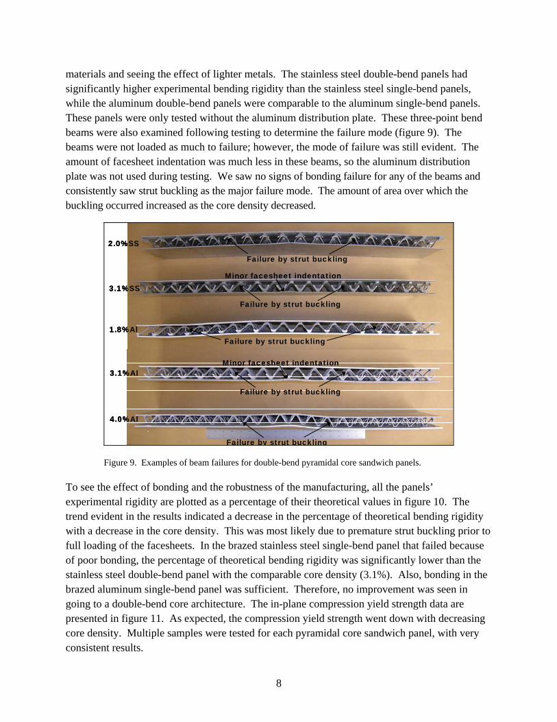
materials and seeing the effect of lighter metals. The stainless steel double-bend panels had significantly higher experimental bending rigidity than the stainless steel single-bend panels, while the aluminum double-bend panels were comparable to the aluminum single-bend panels. These panels were only tested without the aluminum distribution plate. These three-point bend beams were also examined following testing to determine the failure mode (figure 9). The beams were not loaded as much to failure; however, the mode of failure was still evident. The amount of facesheet indentation was much less in these beams, so the aluminum distribution plate was not used during testing. We saw no signs of bonding failure for any of the beams and consistently saw strut buckling as the major failure mode. The amount of area over which the buckling occurred increased as the core density decreased.
2.0%SS
3.1%SS
1.8%Al
3.1%Al
4.0%Al
Failure by strut buckling
Failure by strut buckling
Failure by strut buckling
Minor facesheet indentation
Minor facesheet indentation
Failure by strut buckling
Failure by strut buckling
2.0%SS
3.1%SS
1.8%Al
3.1%Al
4.0%Al
2.0%SS
3.1%SS
1.8%Al
3.1%Al
4.0%Al
Failure by strut buckling
Failure by strut buckling
Failure by strut buckling
Minor facesheet indentation
Minor facesheet indentation
Failure by strut buckling
Failure by strut buckling
Figure 9. Examples of beam failures for double-bend pyramidal core sandwich panels.
To see the effect of bonding and the robustness of the manufacturing, all the panels’ experimental rigidity are plotted as a percentage of their theoretical values in figure 10. The trend evident in the results indicated a decrease in the percentage of theoretical bending rigidity with a decrease in the core density. This was most likely due to premature strut buckling prior to full loading of the facesheets. In the brazed stainless steel single-bend panel that failed because of poor bonding, the percentage of theoretical bending rigidity was significantly lower than the stainless steel double-bend panel with the comparable core density (3.1%). Also, bonding in the brazed aluminum single-bend panel was sufficient. Therefore, no improvement was seen in going to a double-bend core architecture. The in-plane compression yield strength data are presented in figure 11. As expected, the compression yield strength went down with decreasing core density. Multiple samples were tested for each pyramidal core sandwich panel, with very consistent results.
9
0.0
10.0
20.0
30.0
40.0
50.0
60.0
70.0
80.0
90.0
100.0
BrazedSS
WeldedSS
BrazedAl
4% Al 3.1% Al 1.8% Al 3.1% SS 2.0%SS
Truss Core
% o
f T
he
ore
tic
al E
I/b
Figure 10. Experimental values as a percent of the theoretical bending rigidity [(EI)eq/b] for the pyramidal core sandwich beams.
0
50
100
150
200
250
300
350
400
brazed SS 4% Al 3.1% Al 1.8% Al 3.1% SS 2.0% SS
Truss Core
Co
mp
res
sio
n Y
S (
ps
i)
Figure 11. Experimental in-plane compression yield strengths for pyramidal core sandwich panels.
10
4. Discussion
Large pyramidal truss core sandwich panels were fabricated and mechanically tested to determine the effect of minor changes in core architecture on bending and compression performance. These changes included base materials (aluminum vs. stainless steel), core features (single vs. double bend and relative core density), and bonding (brazing vs. laser spot welding) while maintaining the facesheet thickness and panel AD relatively consistent for each material (0.075-in facesheets and ~7 psf for stainless steel panels, 0.125-in facesheets and ~4 psf for aluminum panels). The three-point bend testing of the stainless steel panels revealed the need for improved bonding between the facesheet and core for the first-generation, single-bend panels. This was accomplished by the second-generation, double-bend panels increasing bond area and transitioning the bend test failure to a preferred core buckling and facesheet indentation combination. The design change improved the experimental bending rigidity to almost 90% of the theoretical value from roughly 70% in the original single-bend geometry. Laser spot welding is another option for improving the bonding between the facesheet and core. In the laser spot welding case, stronger bonding instead of increased bonding area transitioned the bending failure to the more accepted failure modes. However, the single-bond stainless steel welded pyramidal truss cores were fabricated at a lower relative core density (2% vs. ~3%) and didn’t perform as well on a specific bending stiffness level. The three-point bend testing of the aluminum panels revealed that the aluminum brazing process was a much more robust process for the joining of facesheets to core. Therefore, no benefit was derived from switching to a double-bend architecture from a single one because there was no failure of the facesheet to core bonding in either case. The comparable second-generation, double-bend aluminum design (3.1% Al) did measure higher specific bending stiffness (theoretical and experimental); however, this was a factor of the overall thickness and not related to bonding or core architecture changes.
After examining all the specific bending stiffness data, the pyramidal truss core sandwich panels with relative core densities of ~3% were the top performers (besting both 2% and 4% in aluminum and stainless steel). When this finding was combined with the trend that the compression yield strength and percentage of the theoretical bending rigidity decreased with decreasing relative core density, the area to focus any further optimization began at roughly 3%. However, this study identified several candidates for structural use with aluminum and stainless steel pyramidal truss core sandwich panels, depending on the weight available in the design.
While pyramidal truss core sandwich panels offered extremely mass-efficient structures for future lightweight ground vehicles, it was necessary that the manufacturing of the panels be extremely consistent and at a reasonable cost. For structural applications, large panels (30 30 in and beyond) with consistent properties and dimensions from middle to edge will be required.
11
Since facesheet to core bonding was very important for sandwich panel performance, the precision of the core fabrication was paramount to allow sufficient bonding at all nodes. This exercise answered some of these manufacturing concerns by the fabrication of pyramidal truss core sandwich panels up to 30 30 in, over a range of core densities, with good flatness and dimensional tolerance consistently from middle to edge. Future concern remains in the ability to commercially fabricate these panels at an affordable cost since they will typically be replacing metallic plate. Low-cost processes must be considered that allow increased scale and production rate to bring down the per-piece cost.
5. Summary
• Large (30 30 in) 6061-T6 aluminum and 316L stainless steel pyramidal core sandwich panels were fabricated with fine quality and good repeatability. Incremental design changes and rigorous manufacturing led to an improvement in the overall product by the end of the process.
• The importance of the joining of facesheets to core for bending performance was revealed and addressed by a new core architecture using a double-bend geometry to increase bond area. This led to a transition to more favorable failure mechanisms and experimental bending rigidity values increasing toward the theoretical values.
• The combination of mechanical tests has demonstrated a balance between compression yield strength and panel bending rigidity. The different core geometries and material options opened up a wide design property range for pyramidal truss core sandwich panels. There were several good candidates that possessed an excellent combination of compression strength and panel bending rigidity.
12
6. References
1. Doherty, K.; Tice, J.; Szewczyk, S.; Gilde, G. Brazing Titanium for Structural and Vehicle Applications. Weld. J. 2007, 86 (9), 41–46.
2. Deshpande, V. S.; Ashby, M. F.; Fleck, N. A. Foam Topology Bending vs. Stretching Dominated Architectures. Acta Mater. 2001, 49, 1035–1040.
3. Sypeck, D. J.; Wadley, H. N. G. Cellular Metal Truss Core Sandwich Structures. Adv. Eng. Mater. 2002, 4 (10), 759–764.
4. Wadley, H. N. G.; Fleck, N. A.; Evans, A. G. Fabrication and Structural Performance of Periodic Cellular Metal Sandwich Structures. Compos. Sci. Technol. 2003, 63 (16), 2331–2343.
5. Evans, A. G. Lightweight Materials and Structures. MRS Bull. 2001, 26 (10), 790–797.
6. Deshpande, V. S.; Fleck, N. A.; Ashby, M. F. Effective Properties of the Octet-Truss Lattice Material. J. Mech. Phys. Solids 2001, 49 (8), 1747–1769.
7. Chiras, S.; Mumm, D. R.; Evans, A. G.; Wicks, N.; Hutchinson, J. W.; Dharmasena, K.; Wadley, H. N. G.; Fichter, S. The Structural Performance of Near-Optimized Truss Core Panels. Int. J. Solids Struct. 2002, 39, 4093–4115.
8. Deshpande, V. S.; Fleck, N. A. Collapse of Truss Core Sandwich Beams in Three-Point Bending. Int. J. Solids Struct. 2001, 38, 6275–6305.
9. Wicks, N.; Hutchinson, J. W. Optimal Truss Plates. Int. J. Solids Struct. 2001, 38, 5165–5183.
10. Radford, D. D.; Fleck, N. A.; Deshpande, V. S. The Response of Clamped Sandwich Beams Subjected to Shock Loading. Int. J. Impact Eng. 2006, 32, 968–987.
11. Brittain, S. T.; Sugimura, Y.; Schueller, O. J. A.; Evans, A. G.; Whitesides, G. M. Fabrication and Mechanical Performance of a Mesoscale Space-Filling Truss System. J. Microelectromech. S. 2001, 10 (1), 113–120.
12. Kooistra, G. W.; Deshpande, V. S.; Wadley, H. N. G. Compressive Behavior of Age Hardenable Tetrahedral Lattice Truss Structures Made from Aluminum. Acta Mater. 2004, 52, 4229–4237.
NO. OF COPIES ORGANIZATION
13
1 DEFENSE TECHNICAL (PDF INFORMATION CTR only) DTIC OCA 8725 JOHN J KINGMAN RD STE 0944 FORT BELVOIR VA 22060-6218 1 DIRECTOR US ARMY RESEARCH LAB IMNE ALC HRR 2800 POWDER MILL RD ADELPHI MD 20783-1197 1 DIRECTOR US ARMY RESEARCH LAB RDRL CIM L 2800 POWDER MILL RD ADELPHI MD 20783-1197 1 DIRECTOR US ARMY RESEARCH LAB RDRL CIM P 2800 POWDER MILL RD ADELPHI MD 20783-1197
ABERDEEN PROVING GROUND 1 DIR USARL RDRL CIM G (BLDG 4600)
NO. OF COPIES ORGANIZATION
14
1 CELLULAR MTRL INTRNTL Y MURTY 2 BOARS HEAD LN CHARLOTTESVILLE VA 22903
ABERDEEN PROVING GROUND 5 DIR USRAL RDRL WMM D K DOHERTY