structural standing seam roof systems -...
TRANSCRIPT
STRUCTURALSTANDING SEAMROOF SYSTEMS
S R S R
M A N U A LDesign
INTRODUCTION
INTRODUCTION The System.................................................................................1Panels ........................................................................................2SRS 2 and SRS 3 Basic Differences..............................................3Curving.......................................................................................4Accessories .............................................................................5-9Fasteners..................................................................................10Sealants ...................................................................................11Tools ........................................................................................12Corrosion Prevention .................................................................13
DESIGN CONSIDERATIONSBuilding Design Codes...............................................................14Structural ............................................................................14-15Panel Gage Selection.................................................................15Allowable Loads...................................................................16-20Product Description ...................................................................21Underwriters LaboratoriesWind Uplift Classification............................................................21Comparison of ASTM 1592 and UL90 ........................................21Fire Resistance .........................................................................22System Weathertightness ..........................................................22Minimum Slope .........................................................................22Purlin Design Considerations ................................................23-24Thermal Movement ..............................................................24-25Thermal Insulation.....................................................................26Roof Space Ventilation ...............................................................26Moisture Control........................................................................27Roof Drainage Systems..............................................................27Snow Country Precautions....................................................27-28
DESIGN DETAILSFor panel details, please refer to the CENTRIA website and portal.www.CENTRIA.com
Hylar 5000TM is a registered trademark of Ausimont, U.S.A., Inc.;
Kynar 500® is a registered trademark of Elf Atochem North America, Inc.
UL® is a registered trademark of Underwriters Laboratories.
Galvalume® is a registered trademark of BIEC International, Inc.
BULBTITETM is a trademark of Gesipa Fasteners USA, Inc.
Tapcon® is a registered trademark of Buildex®.
ROOFGRIP™ is a trademark of Buildex®.
Contact CENTRIA for a copy of SRS® Installation General Notes Sheets.
CENTRIA reserves the right to change information within this manual without prior notice.
This design manual presents only a general description of the CENTRIA SRS Standing SeamRoof Systems. The drawings and other information contained herein are intended only to pro-vide a general description of the SRS Systems and are not intended to provide the specificdesign for any particular installation of an SRS System. CENTRIA expressly disclaims any lia-bility arising from the use of such drawings in the design of any installation of SRS Systems.CENTRIA EXCLUDES ANY IMPLIED WARRANTY OF FITNESS FOR A PARTICULAR PURPOSE OROF MERCHANTABILITY WITH RESPECT TO ANY PANELS DESCRIBED IN THIS MANUAL.
1
INTRODUCTION
THE SYSTEM
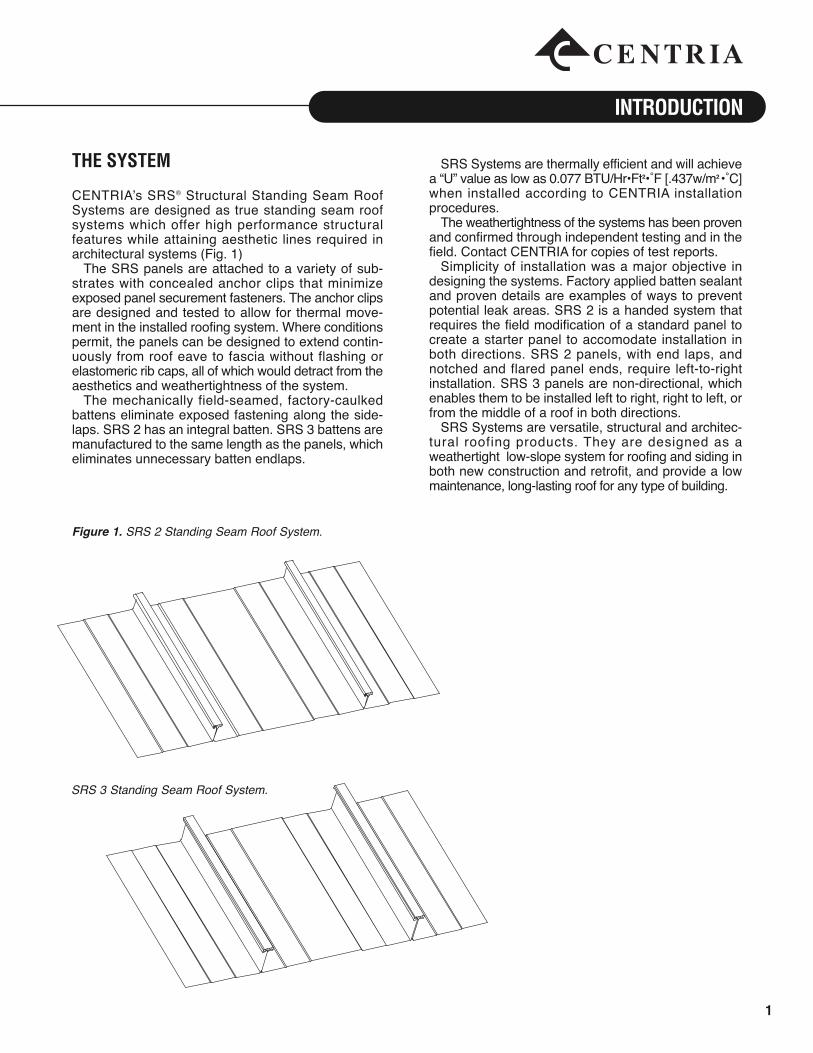
CENTRIA’s SRS® Structural Standing Seam RoofSystems are designed as true standing seam roof systems which offer high performance structuralfeatures while attaining aesthetic lines required inarchitectural systems (Fig. 1)
The SRS panels are attached to a variety of sub-strates with concealed anchor clips that minimizeexposed panel securement fasteners. The anchor clipsare designed and tested to allow for thermal move-ment in the installed roofing system. Where conditionspermit, the panels can be designed to extend contin-uously from roof eave to fascia without flashing orelastomeric rib caps, all of which would detract from theaesthetics and weathertightness of the system.
The mechanically field-seamed, factory-caulkedbattens eliminate exposed fastening along the side-laps. SRS 2 has an integral batten. SRS 3 battens aremanufactured to the same length as the panels, whicheliminates unnecessary batten endlaps.
SRS Systems are thermally efficient and will achievea “U” value as low as 0.077 BTU/Hr•Ft2•˚F [.437w/m2 •˚C]when installed according to CENTRIA installationprocedures.
The weathertightness of the systems has been provenand confirmed through independent testing and in thefield. Contact CENTRIA for copies of test reports.
Simplicity of installation was a major objective indesigning the systems. Factory applied batten sealantand proven details are examples of ways to preventpotential leak areas. SRS 2 is a handed system thatrequires the field modification of a standard panel to create a starter panel to accomodate installation inboth directions. SRS 2 panels, with end laps, andnotched and flared panel ends, require left-to-rightinstallation. SRS 3 panels are non-directional, whichenables them to be installed left to right, right to left, orfrom the middle of a roof in both directions.
SRS Systems are versatile, structural and architec-tural roofing products. They are designed as aweathertight low-slope system for roofing and siding inboth new construction and retrofit, and provide a lowmaintenance, long-lasting roof for any type of building.
Figure 1. SRS 2 Standing Seam Roof System.
Figure 1. SRS 3 Standing Seam Roof System.
2
16 or 18"[406mm or 457mm]
3"
Exterior [32mm]
[76m
m]
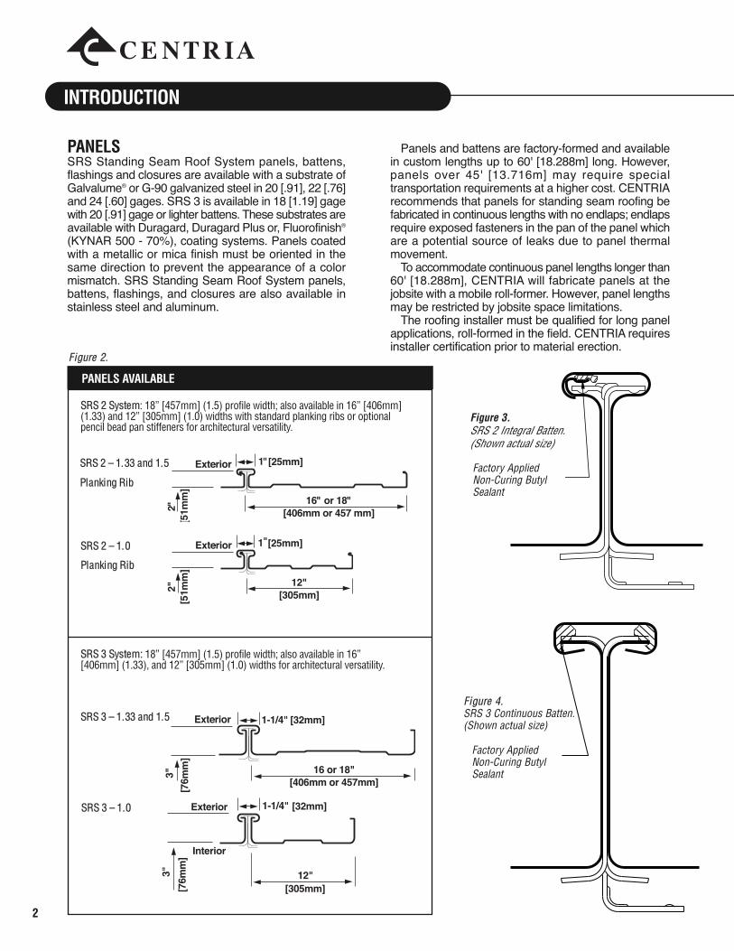
PANELSSRS Standing Seam Roof System panels, battens,flashings and closures are available with a substrate ofGalvalume® or G-90 galvanized steel in 20 [.91], 22 [.76]and 24 [.60] gages. SRS 3 is available in 18 [1.19] gagewith 20 [.91] gage or lighter battens. These substrates areavailable with Duragard, Duragard Plus or, Fluorofinish®
(KYNAR 500 - 70%), coating systems. Panels coatedwith a metallic or mica finish must be oriented in thesame direction to prevent the appearance of a colormismatch. SRS Standing Seam Roof System panels,battens, flashings, and closures are also available instainless steel and aluminum.
Panels and battens are factory-formed and availablein custom lengths up to 60' [18.288m] long. However,panels over 45' [13.716m] may require specialtransportation requirements at a higher cost. CENTRIArecommends that panels for standing seam roofing befabricated in continuous lengths with no endlaps; endlapsrequire exposed fasteners in the pan of the panel whichare a potential source of leaks due to panel thermalmovement.
To accommodate continuous panel lengths longer than60' [18.288m], CENTRIA will fabricate panels at thejobsite with a mobile roll-former. However, panel lengthsmay be restricted by jobsite space limitations.
The roofing installer must be qualified for long panelapplications, roll-formed in the field. CENTRIA requiresinstaller certification prior to material erection.
INTRODUCTION
Figure 2.
SRS 2 System: 18” [457mm] (1.5) profile width; also available in 16” [406mm](1.33) and 12” [305mm] (1.0) widths with standard planking ribs or optionalpencil bead pan stiffeners for architectural versatility.
PANELS AVAILABLE
SRS 3 System: 18” [457mm] (1.5) profile width; also available in 16”[406mm] (1.33), and 12” [305mm] (1.0) widths for architectural versatility.
16" or 18"
[406mm or 457 mm]
2"
[51m
m]
Exterior [25mm]SRS 2 – 1.33 and 1.5
Planking Rib
SRS 2 – 1.0
Planking Rib
SRS 3 – 1.33 and 1.5
SRS 3 – 1.0
2"[5
1mm
]
Exterior
12"[305mm]
[25mm]
Factory AppliedNon-Curing ButylSealant
Figure 4. SRS 3 Continuous Batten. (Shown actual size)
Factory AppliedNon-Curing ButylSealant
[32mm]
[305mm][76mm]
Figure 3. SRS 2 Integral Batten. (Shown actual size)
3
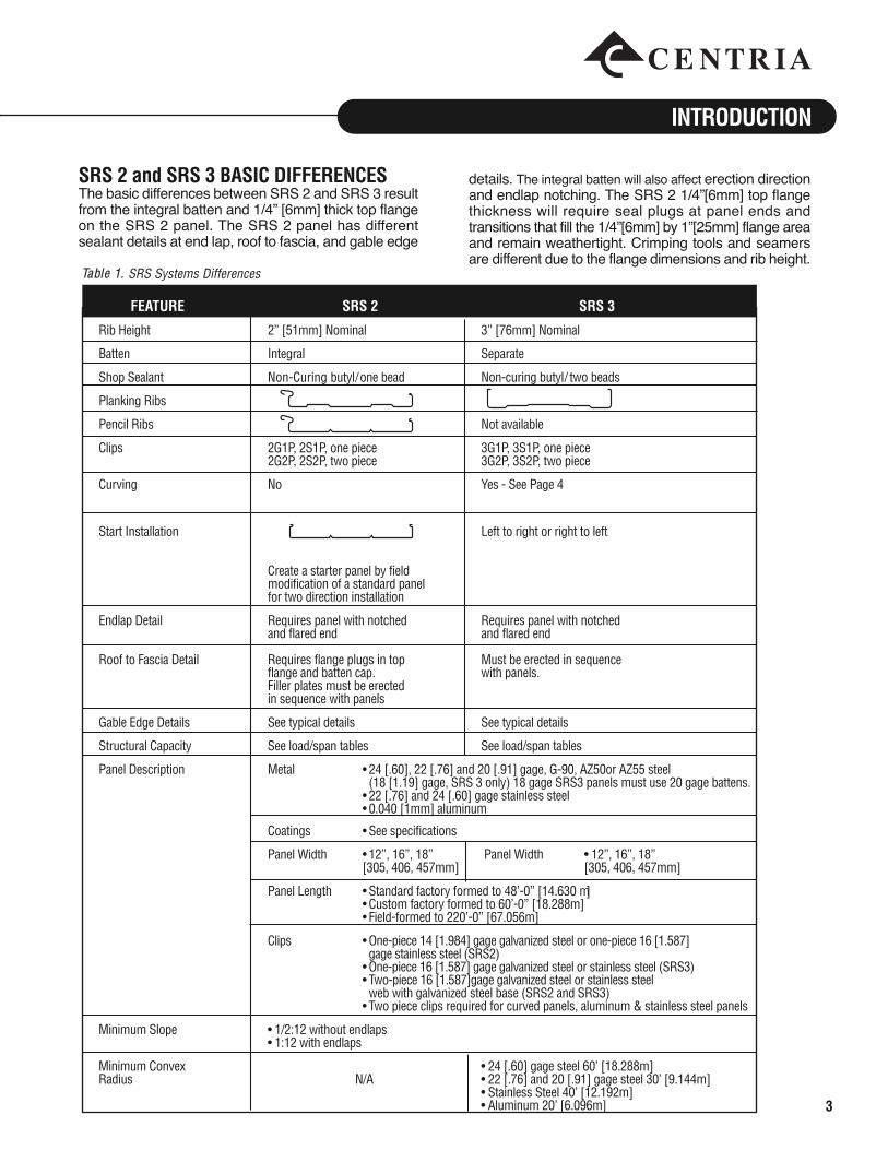
SRS 2 and SRS 3 BASIC DIFFERENCESThe basic differences between SRS 2 and SRS 3 resultfrom the integral batten and 1/4” [6mm] thick top flangeon the SRS 2 panel. The SRS 2 panel has differentsealant details at end lap, roof to fascia, and gable edge
details. The integral batten will also affect erection directionand endlap notching. The SRS 2 1/4”[6mm] top flangethickness will require seal plugs at panel ends andtransitions that fill the 1/4”[6mm] by 1”[25mm] flange areaand remain weathertight. Crimping tools and seamersare different due to the flange dimensions and rib height.
INTRODUCTION
Table 1. SRS Systems Differences
FEATURE SRS 2 SRS 3
Rib Height 2” [51mm] Nominal 3” [76mm] Nominal
Batten Integral Separate
Shop Sealant Non-Curing butyl/one bead Non-curing butyl/ two beads
Planking Ribs
Pencil Ribs Not available
Clips 2G1P, 2S1P, one piece 3G1P, 3S1P, one piece2G2P, 2S2P, two piece 3G2P, 3S2P, two piece
Curving No Yes - See Page 4
Start Installation Left to right or right to left
Create a starter panel by fieldmodification of a standard panel for two direction installation
Endlap Detail Requires panel with notched Requires panel with notched and flared end and flared end
Roof to Fascia Detail Requires flange plugs in top Must be erected in sequenceflange and batten cap. with panels.Filler plates must be erectedin sequence with panels
Gable Edge Details See typical details See typical details
Structural Capacity See load/span tables See load/span tables
Panel Description Metal • 24 [.60], 22 [.76] and 20 [.91] gage, G-90, AZ50or AZ55 steel (18 [1.19] gage, SRS 3 only) 18 gage SRS3 panels must use 20 gage battens.• 22 [.76] and 24 [.60] gage stainless steel• 0.040 [1mm] aluminum
Coatings • See specifications
Panel Width • 12”, 16”, 18” Panel Width • 12”, 16”, 18”[305, 406, 457mm] [305, 406, 457mm]
Panel Length • Standard factory formed to 48’-0” [14.630 m]• Custom factory formed to 60’-0” [18.288m]• Field-formed to 220’-0” [67.056m]
Clips • One-piece 14 [1.984] gage galvanized steel or one-piece 16 [1.587]gage stainless steel (SRS2)• One-piece 16 [1.587] gage galvanized steel or stainless steel (SRS3)• Two-piece 16 [1.587]gage galvanized steel or stainless steel web with galvanized steel base (SRS2 and SRS3)• Two piece clips required for curved panels, aluminum & stainless steel panels
Minimum Slope • 1/2:12 without endlaps• 1:12 with endlaps
Minimum Convex • 24 [.60] gage steel 60’ [18.288m]Radius N/A • 22 [.76] and 20 [.91] gage steel 30’ [9.144m]
• Stainless Steel 40’ [12.192m]• Aluminum 20’ [6.096m]
4
CURVING
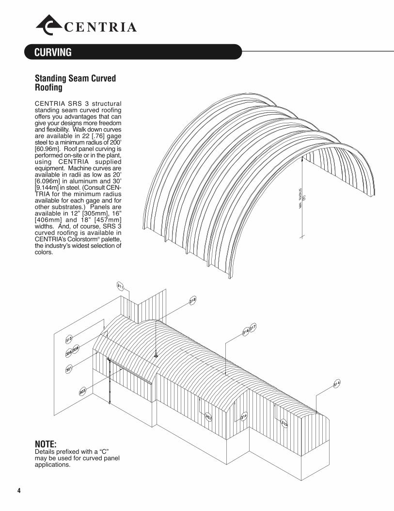
Standing Seam CurvedRoofing
CENTRIA SRS 3 structuralstanding seam curved roofingoffers you advantages that cangive your designs more freedomand flexibility. Walk down curvesare available in 22 [.76] gagesteel to a minimum radius of 200’[60.96m]. Roof panel curving isperformed on-site or in the plant,using CENTRIA suppliedequipment. Machine curves areavailable in radii as low as 20’[6.096m] in aluminum and 30’[9.144m] in steel. (Consult CEN-TRIA for the minimum radiusavailable for each gage and forother substrates.) Panels areavailable in 12” [305mm], 16”[406mm] and 18” [457mm]widths. And, of course, SRS 3curved roofing is available inCENTRIA’s Colorstorm® palette,the industry’s widest selection ofcolors.
NOTE:Details prefixed with a “C”may be used for curved panelapplications.
5
ACCESSORIES
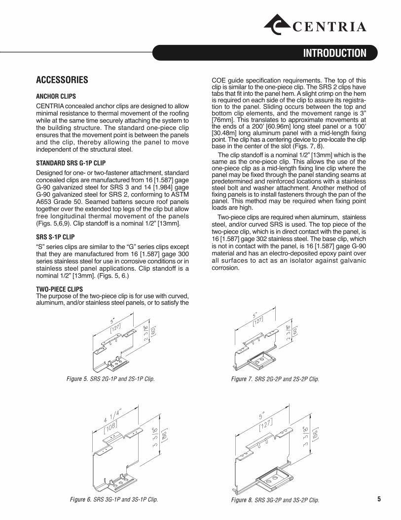
ANCHOR CLIPSCENTRIA concealed anchor clips are designed to allowminimal resistance to thermal movement of the roofingwhile at the same time securely attaching the system tothe building structure. The standard one-piece clipensures that the movement point is between the panelsand the clip, thereby allowing the panel to moveindependent of the structural steel.
STANDARD SRS G-1P CLIPDesigned for one- or two-fastener attachment, standardconcealed clips are manufactured from 16 [1.587] gageG-90 galvanized steel for SRS 3 and 14 [1.984] gageG-90 galvanized steel for SRS 2, conforming to ASTMA653 Grade 50. Seamed battens secure roof panelstogether over the extended top legs of the clip but allowfree longitudinal thermal movement of the panels(Figs. 5,6,9). Clip standoff is a nominal 1/2” [13mm].
SRS S-1P CLIP“S” series clips are similar to the “G” series clips exceptthat they are manufactured from 16 [1.587] gage 300series stainless steel for use in corrosive conditions or instainless steel panel applications. Clip standoff is anominal 1/2” [13mm]. (Figs. 5, 6.)
TWO-PIECE CLIPSThe purpose of the two-piece clip is for use with curved,aluminum, and/or stainless steel panels, or to satisfy the
COE guide specification requirements. The top of thisclip is similar to the one-piece clip. The SRS 2 clips havetabs that fit into the panel hem. A slight crimp on the hemis required on each side of the clip to assure its registra-tion to the panel. Sliding occurs between the top andbottom clip elements, and the movement range is 3”[76mm]. This translates to approximate movements atthe ends of a 200’ [60.96m] long steel panel or a 100’[30.48m] long aluminum panel with a mid-length fixingpoint. The clip has a centering device to pre-locate the clipbase in the center of the slot (Figs. 7, 8).
The clip standoff is a nominal 1/2” [13mm] which is thesame as the one-piece clip. This allows the use of theone-piece clip as a mid-length fixing line clip where thepanel may be fixed through the panel standing seams atpredetermined and reinforced locations with a stainlesssteel bolt and washer attachment. Another method offixing panels is to install fasteners through the pan of thepanel. This method may be required when fixing pointloads are high.
Two-piece clips are required when aluminum, stainlesssteel, and/or curved SRS is used. The top piece of thetwo- piece clip, which is in direct contact with the panel, is16 [1.587] gage 302 stainless steel. The base clip, whichis not in contact with the panel, is 16 [1.587] gage G-90material and has an electro-deposited epoxy paint overall surfaces to act as an isolator against galvaniccorrosion.
Figure 6. SRS 3G-1P and 3S-1P Clip. Figure 8. SRS 3G-2P and 3S-2P Clip.
Figure 7. SRS 2G-2P and 2S-2P Clip.Figure 5. SRS 2G-1P and 2S-1P Clip.
INTRODUCTION

6
INTRODUCTION
Figure 9. SRS System Over Purlins
Figure 10. SRS System Over Plywood Deck
7
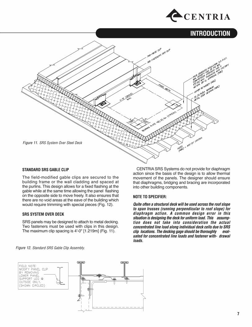
STANDARD SRS GABLE CLIP
The field-modified gable clips are secured to the building frame or the wall cladding and spaced at the purlins. This design allows for a fixed flashing at thegable while at the same time allowing the panel flashingon the opposite side to move freely. It also ensures thatthere are no void areas at the eave of the building whichwould require trimming with special pieces (Fig. 12).
SRS SYSTEM OVER DECK
SRS panels may be designed to attach to metal decking.Two fasteners must be used with clips in this design.The maximum clip spacing is 4'-0" [1.219m] (Fig. 11).
CENTRIA SRS Systems do not provide for diaphragmaction since the basis of the design is to allow thermalmovement of the panels. The designer should ensurethat diaphragms, bridging and bracing are incorporatedinto other building components.
NOTE TO SPECIFIER:
Quite often a structural deck will be used across the roof slopeto span trusses (running perpendicular to roof slope) fordiaphragm action. A common design error in this situation is designing the deck for uniform load. This assump-tion does not take into consideration the actualconcentrated line load along individual deck cells due to SRSclip locations. The decking gage should be thoroughly eval-uated for concentrated line loads and fastener with- drawalloads.
INTRODUCTION
Figure 12. Standard SRS Gable Clip Assembly.
Figure 11. SRS System Over Steel Deck
8
INTRODUCTION
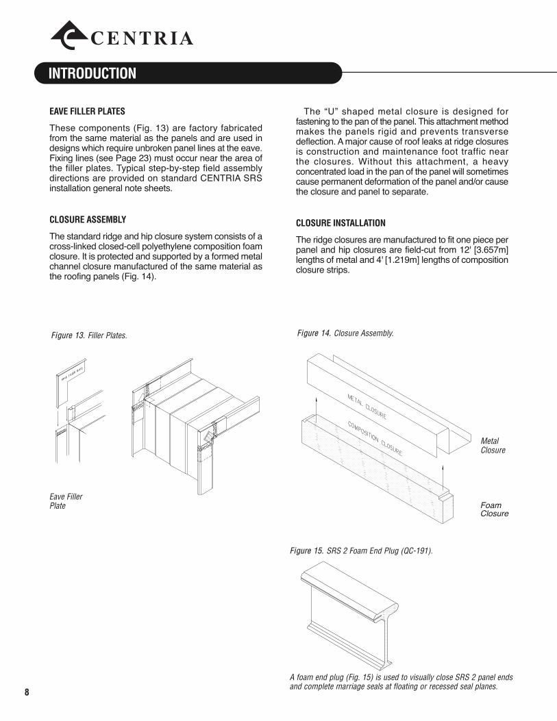
EAVE FILLER PLATES
These components (Fig. 13) are factory fabricated from the same material as the panels and are used indesigns which require unbroken panel lines at the eave.Fixing lines (see Page 23) must occur near the area ofthe filler plates. Typical step-by-step field assemblydirections are provided on standard CENTRIA SRSinstallation general note sheets.
CLOSURE ASSEMBLY
The standard ridge and hip closure system consists of across-linked closed-cell polyethylene composition foamclosure. It is protected and supported by a formed metalchannel closure manufactured of the same material asthe roofing panels (Fig. 14).
Figure 13. Filler Plates.
Eave Filler Plate
Figure 14. Closure Assembly.
Figure 15. SRS 2 Foam End Plug (QC-191).
A foam end plug (Fig. 15) is used to visually close SRS 2 panel endsand complete marriage seals at floating or recessed seal planes.
Metal Closure
Foam Closure
The “U” shaped metal closure is designed forfastening to the pan of the panel. This attachment methodmakes the panels rigid and prevents transversedeflection. A major cause of roof leaks at ridge closuresis construction and maintenance foot traffic nearthe closures. Without this attachment, a heavyconcentrated load in the pan of the panel will sometimescause permanent deformation of the panel and/or causethe closure and panel to separate.
CLOSURE INSTALLATION
The ridge closures are manufactured to fit one piece perpanel and hip closures are field-cut from 12' [3.657m]lengths of metal and 4' [1.219m] lengths of compositionclosure strips.
9
INTRODUCTION
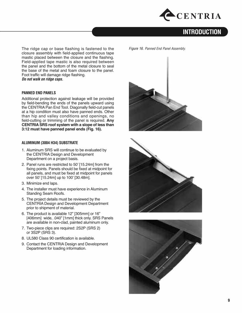
The ridge cap or base flashing is fastened to the closure assembly with field-applied continuous tapemastic placed between the closure and the flashing.Field-applied tape mastic is also required between the panel and the bottom of the metal closure to seal the base of the metal and foam closure to the panel. Foot traffic will damage ridge flashing. Do not walk on ridge caps.
PANNED END PANELSAdditional protection against leakage will be providedby field-bending the ends of the panels upward usingthe CENTRIA Pan End Tool. Diagonally field-cut panelsat a hip condition must also have panned ends. Otherthan hip and valley conditions and openings, nofield-cutting or trimming of the panel is required. AnyCENTRIA SRS roof system with a slope of less than3:12 must have panned panel ends (Fig. 16).
ALUMINUM (3004 H34) SUBSTRATE
1. Aluminum SRS will continue to be evaluated by the CENTRIA Design and DevelopmentDepartment on a project basis.
2. Panel runs are restricted to 50’ [15.24m] from thefixing points. Panels should be fixed at midpoint forall panels, and must be fixed at midpoint for panelsover 50’ [15.24m] up to 100’ [30.48m].
3. Minimize end laps.
4. The installer must have experience in AluminumStanding Seam Roofs.
5. The project details must be reviewed by the CENTRIA Design and Development Departmentprior to shipment of material.
6. The product is available 12” [305mm] or 16”[406mm] wide, .040” [1mm] thick only. SRS Panelsare available in non-clad, painted aluminum only.
7. Two-piece clips are required: 2S2P (SRS 2) or 3S2P (SRS 3).
8. UL580 Class 90 certification is available.
9. Contact the CENTRIA Design and DevelopmentDepartment for loading information.
Figure 16. Panned End Panel Assembly.
10
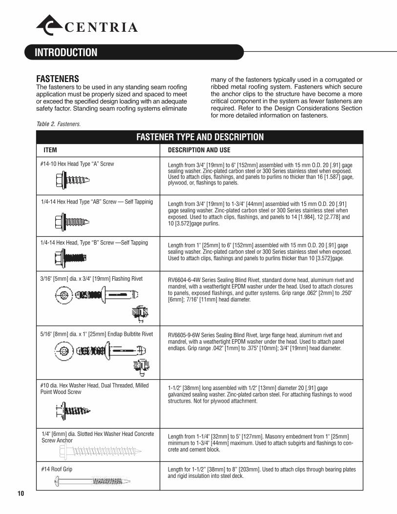
FASTENERS The fasteners to be used in any standing seam roofingapplication must be properly sized and spaced to meetor exceed the specified design loading with an adequatesafety factor. Standing seam roofing systems eliminate
Table 2. Fasteners.
many of the fasteners typically used in a corrugated orribbed metal roofing system. Fasteners which securethe anchor clips to the structure have become a morecritical component in the system as fewer fasteners arerequired. Refer to the Design Considerations Sectionfor more detailed information on fasteners.
FASTENER TYPE AND DESCRIPTIONDESCRIPTION AND USEITEM
Length from 3/4" [19mm] to 6" [152mm] assembled with 15 mm O.D. 20 [.91] gagesealing washer. Zinc-plated carbon steel or 300 Series stainless steel when exposed.Used to attach clips, flashings, and panels to purlins no thicker than 16 [1.587] gage,plywood, or, flashings to panels.
Length from 1-1/4" [32mm] to 5" [127mm]. Masonry embedment from 1" [25mm]minimum to 1-3/4" [44mm] maximum. Used to attach subgirts and flashings to con-crete and cement block.
1-1/2" [38mm] long assembled with 1/2" [13mm] diameter 20 [.91] gage galvanized sealing washer. Zinc-plated carbon steel. For attaching flashings to woodstructures. Not for plywood attachment.
RV6605-9-6W Series Sealing Blind Rivet, large flange head, aluminum rivet andmandrel, with a weathertight EPDM washer under the head. Used to attach panelendlaps. Grip range .042" [1mm] to .375" [10mm]; 3/4" [19mm] head diameter.
RV6604-6-4W Series Sealing Blind Rivet, standard dome head, aluminum rivet andmandrel, with a weathertight EPDM washer under the head. Used to attach closuresto panels, exposed flashings, and gutter systems. Grip range .062" [2mm] to .250"[6mm]; 7/16" [11mm] head diameter.
Length from 1" [25mm] to 6" [152mm] assembled with 15 mm O.D. 20 [.91] gagesealing washer. Zinc-plated carbon steel or 300 Series stainless steel when exposed.Used to attach clips, flashings and panels to purlins thicker than 10 [3.572]gage.
#14-10 Hex Head Type “A” Screw
#10 dia. Hex Washer Head, Dual Threaded, MilledPoint Wood Screw
5/16" [8mm] dia. x 1" [25mm] Endlap Bulbtite Rivet
3/16" [5mm] dia. x 3/4" [19mm] Flashing Rivet
1/4-14 Hex Head, Type “B” Screw —Self Tapping
Length from 3/4" [19mm] to 1-3/4" [44mm] assembled with 15 mm O.D. 20 [.91]gage sealing washer. Zinc-plated carbon steel or 300 Series stainless steel whenexposed. Used to attach clips, flashings, and panels to 14 [1.984], 12 [2.778] and10 [3.572]gage purlins.
1/4-14 Hex Head Type “AB” Screw — Self Tappinig
#14 Roof Grip Length for 1-1/2” [38mm] to 8” [203mm]. Used to attach clips through bearing platesand rigid insulation into steel deck.
INTRODUCTION
1/4" [6mm] dia. Slotted Hex Washer Head ConcreteScrew Anchor
11
INTRODUCTION
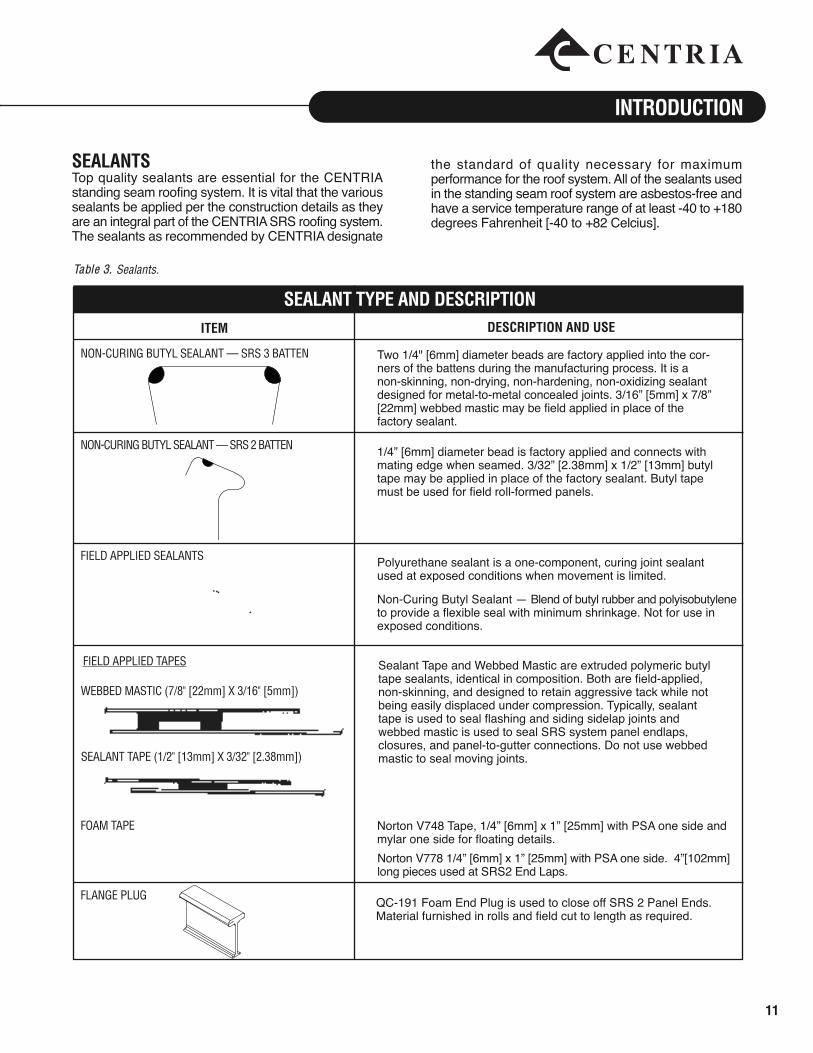
SEALANTSTop quality sealants are essential for the CENTRIAstanding seam roofing system. It is vital that the varioussealants be applied per the construction details as theyare an integral part of the CENTRIA SRS roofing system.The sealants as recommended by CENTRIA designate
the standard of quality necessary for maximumperformance for the roof system. All of the sealants usedin the standing seam roof system are asbestos-free andhave a service temperature range of at least -40 to +180degrees Fahrenheit [-40 to +82 Celcius].
Table 3. Sealants.
DESCRIPTION AND USEITEM
Two 1/4" [6mm] diameter beads are factory applied into the cor-ners of the battens during the manufacturing process. It is anon-skinning, non-drying, non-hardening, non-oxidizing sealantdesigned for metal-to-metal concealed joints. 3/16” [5mm] x 7/8”[22mm] webbed mastic may be field applied in place of the factory sealant.
Sealant Tape and Webbed Mastic are extruded polymeric butyltape sealants, identical in composition. Both are field-applied,non-skinning, and designed to retain aggressive tack while notbeing easily displaced under compression. Typically, sealanttape is used to seal flashing and siding sidelap joints andwebbed mastic is used to seal SRS system panel endlaps, closures, and panel-to-gutter connections. Do not use webbedmastic to seal moving joints.
Polyurethane sealant is a one-component, curing joint sealantused at exposed conditions when movement is limited.
NON-CURING BUTYL SEALANT — SRS 3 BATTEN
SEALANT TAPE (1/2" [13mm] X 3/32" [2.38mm])
FOAM TAPE
WEBBED MASTIC (7/8" [22mm] X 3/16" [5mm])
1/4” [6mm] diameter bead is factory applied and connects withmating edge when seamed. 3/32” [2.38mm] x 1/2” [13mm] butyltape may be applied in place of the factory sealant. Butyl tapemust be used for field roll-formed panels.
NON-CURING BUTYL SEALANT — SRS 2 BATTEN
Non-Curing Butyl Sealant — Blend of butyl rubber and polyisobutyleneto provide a flexible seal with minimum shrinkage. Not for use inexposed conditions.
Norton V748 Tape, 1/4” [6mm] x 1” [25mm] with PSA one side andmylar one side for floating details.
SEALANT TYPE AND DESCRIPTION
QC-191 Foam End Plug is used to close off SRS 2 Panel Ends.Material furnished in rolls and field cut to length as required.
FLANGE PLUG
FIELD APPLIED SEALANTS
FIELD APPLIED TAPES
Norton V778 1/4” [6mm] x 1” [25mm] with PSA one side. 4”[102mm]long pieces used at SRS2 End Laps.
12
TOOLS
SRS Roofing Systems utilize standard hand tools whichare normally required for installing metal roofing andsiding. In addition, the following tools are available fromCENTRIA to ensure weathertightness of the system.
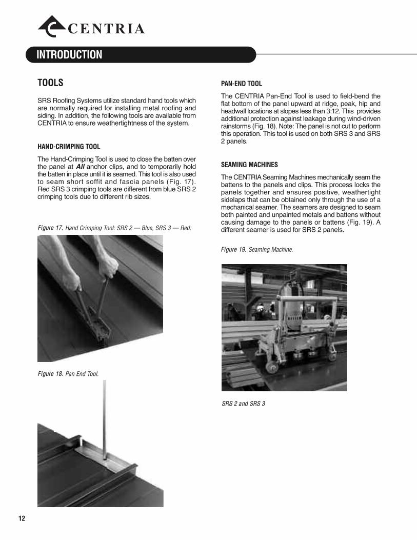
HAND-CRIMPING TOOL
The Hand-Crimping Tool is used to close the batten overthe panel at All anchor clips, and to temporarily holdthe batten in place until it is seamed. This tool is also usedto seam short soffit and fascia panels (Fig. 17).Red SRS 3 crimping tools are different from blue SRS 2crimping tools due to different rib sizes.
Figure 17. Hand Crimping Tool: SRS 2 — Blue, SRS 3 — Red.
Figure 18. Pan End Tool.
Figure 19. Seaming Machine.
PAN-END TOOL
The CENTRIA Pan-End Tool is used to field-bend theflat bottom of the panel upward at ridge, peak, hip andheadwall locations at slopes less than 3:12. This providesadditional protection against leakage during wind-drivenrainstorms (Fig. 18). Note: The panel is not cut to performthis operation. This tool is used on both SRS 3 and SRS2 panels.
SEAMING MACHINES
The CENTRIA Seaming Machines mechanically seam thebattens to the panels and clips. This process locks thepanels together and ensures positive, weathertightsidelaps that can be obtained only through the use of amechanical seamer. The seamers are designed to seamboth painted and unpainted metals and battens withoutcausing damage to the panels or battens (Fig. 19). Adifferent seamer is used for SRS 2 panels.
INTRODUCTION
SRS 2 and SRS 3
13
CORROSION PREVENTION
Potential corrosion problems can be eliminated bybuilding design and proper material handling and storage.
Water staining on unpainted metal panels is the resultof minor surface corrosion due to moisture trappedwithin the panel bundles or ponding water on the roof ofthe building. Ponding water can be eliminated bydesigning sufficient slope into the roofing system.Moisture in the bundles can be eliminated by usingproper storage procedures. Water staining due toimproper storage and erection can affect the integrity ofboth the metal and coating.
Condensation on the underside of the panels mustalso be avoided through proper use of thermal blocks andvapor barriers. Thermal blocks limit conductive heat
transfer in the roof assembly. Vapor barriers preventmoisture from escaping the “building envelope”. Heatinga building in the winter season will drive moisture intothe insulation or cause it to condense on the relatively coldroof panels.
Standard untreated framing lumber and plywood arerecommended by CENTRIA, and will not affect the SRSpanels. Clips and panels should not come into contact withtreated wood, redwood or red cedar. Many preservativesused in treated lumbers contain acid, copper chromateand other forms of copper in various solutions, all ofwhich are highly corrosive to unpainted metal. Salts usedin fire retardant treated wood will also corrode unpaintedmetal roofing (Table 4).
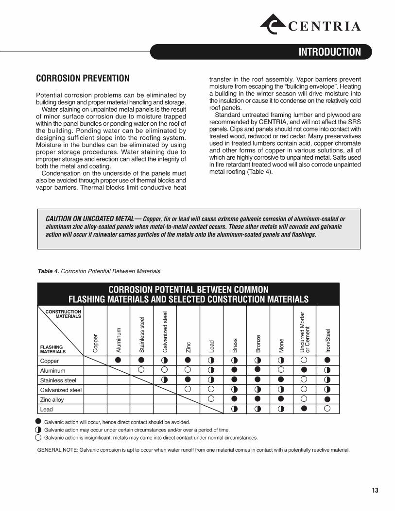
Table 4. Corrosion Potential Between Materials.
CAUTION ON UNCOATED METAL— Copper, tin or lead will cause extreme galvanic corrosion of aluminum-coated oraluminum zinc alloy-coated panels when metal-to-metal contact occurs. These other metals will corrode and galvanicaction will occur if rainwater carries particles of the metals onto the aluminum-coated panels and flashings.
CORROSION POTENTIAL BETWEEN COMMON FLASHING MATERIALS AND SELECTED CONSTRUCTION MATERIALS
FLASHING MATERIALS
Copper
Aluminum
Stainless steel
Galvanized steel
Zinc alloy
Lead
Alu
min
um
Copper
Sta
inle
ss s
teel
Galv
aniz
ed s
teel
Zin
c
Lead
Bra
ss
Bro
nze
Monel
Uncu
rred M
ort
ar
or
Cem
ent
Iron/S
teel
Galvanic action will occur, hence direct contact should be avoided.
Galvanic action may occur under certain circumstances and/or over a period of time.
Galvanic action is insignificant, metals may come into direct contact under normal circumstances.
GENERAL NOTE: Galvanic corrosion is apt to occur when water runoff from one material comes in contact with a potentially reactive material.
CONSTRUCTIONMATERIALS
INTRODUCTION
14
DESIGN CONSIDERATIONS
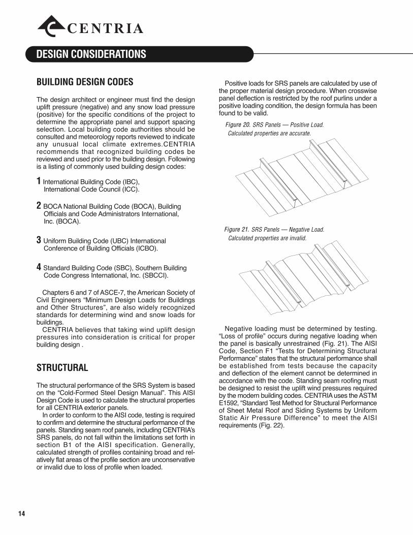
Positive loads for SRS panels are calculated by use ofthe proper material design procedure. When crosswisepanel deflection is restricted by the roof purlins under apositive loading condition, the design formula has beenfound to be valid.
Negative loading must be determined by testing. “Loss of profile” occurs during negative loading whenthe panel is basically unrestrained (Fig. 21). The AISICode, Section F1 “Tests for Determining StructuralPerformance” states that the structural performance shallbe established from tests because the capacity and deflection of the element cannot be determined inaccordance with the code. Standing seam roofing mustbe designed to resist the uplift wind pressures requiredby the modern building codes. CENTRIA uses the ASTME1592, “Standard Test Method for Structural Performanceof Sheet Metal Roof and Siding Systems by UniformStatic Air Pressure Difference” to meet the AISIrequirements (Fig. 22).
BUILDING DESIGN CODES
The design architect or engineer must find the designuplift pressure (negative) and any snow load pressure(positive) for the specific conditions of the project todetermine the appropriate panel and support spacingselection. Local building code authorities should beconsulted and meteorology reports reviewed to indicateany unusual local climate extremes.CENTRIArecommends that recognized building codes bereviewed and used prior to the building design. Followingis a listing of commonly used building design codes:
1 International Building Code (IBC), International Code Council (ICC).
2 BOCA National Building Code (BOCA), Building Officials and Code Administrators International, Inc. (BOCA).
3 Uniform Building Code (UBC) InternationalConference of Building Officials (ICBO).
4 Standard Building Code (SBC), Southern BuildingCode Congress International, Inc. (SBCCI).
Chapters 6 and 7 of ASCE-7, the American Society ofCivil Engineers “Minimum Design Loads for Buildingsand Other Structures”, are also widely recognizedstandards for determining wind and snow loads forbuildings.
CENTRIA believes that taking wind uplift designpressures into consideration is critical for proper building design .
STRUCTURAL
The structural performance of the SRS System is basedon the “Cold-Formed Steel Design Manual”. This AISIDesign Code is used to calculate the structural propertiesfor all CENTRIA exterior panels.
In order to conform to the AISI code, testing is requiredto confirm and determine the structural performance of thepanels. Standing seam roof panels, including CENTRIA’sSRS panels, do not fall within the limitations set forth insection B1 of the AISI specification. Generally,calculated strength of profiles containing broad and rel-atively flat areas of the profile section are unconservativeor invalid due to loss of profile when loaded.
Figure 20. SRS Panels — Positive Load.
Figure 21. SRS Panels — Negative Load.Calculated properties are invalid.
Calculated properties are accurate.
15
DESIGN CONSIDERATIONS
The uplift test procedures used by CENTRIA are similar to those followed by the Factory Mutual ResearchCorporation. The test results and procedures are verifiedby a professional engineer.
The Underwriters Laboratories UL 580 test procedureis intended to provide only a basis for design and forjurisdictive authorities to make a determination onappropriate roof assemblies. The UL 580 test is notintended to quantify the performance of a roof assemblyin actual field conditions. The purpose of the test is toevaluate the comparative resistance of roof assembliesto positive and negative pressures.
PANEL GAGE SELECTION
In designing for economy, the most efficient use of theSRS Systems will result from utilizing the lightest panelgage permitting the maximum allowable span whilemeeting all of the durability and strength requirements.Purlin sizing, spacing and selection can then be determined.
Extra care should be taken by the installer to preventconstruction traffic damage. Foot traffic near the purlinswill not damage panels which have the battens installed,crimped and seamed.
DRILL SIZES FOR SELF-TAPPING FASTENERS
The use of recommended drill sizes for pilot holes ofself-tapping fasteners is critical. See CENTRIA GeneralNotes Sheets.
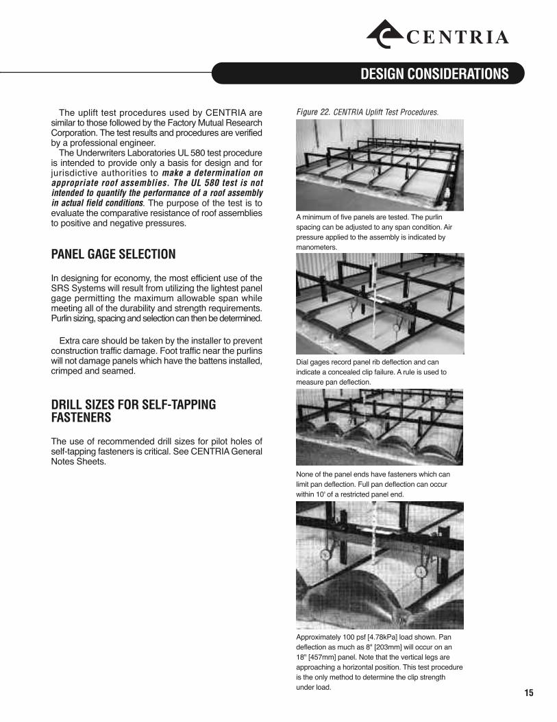
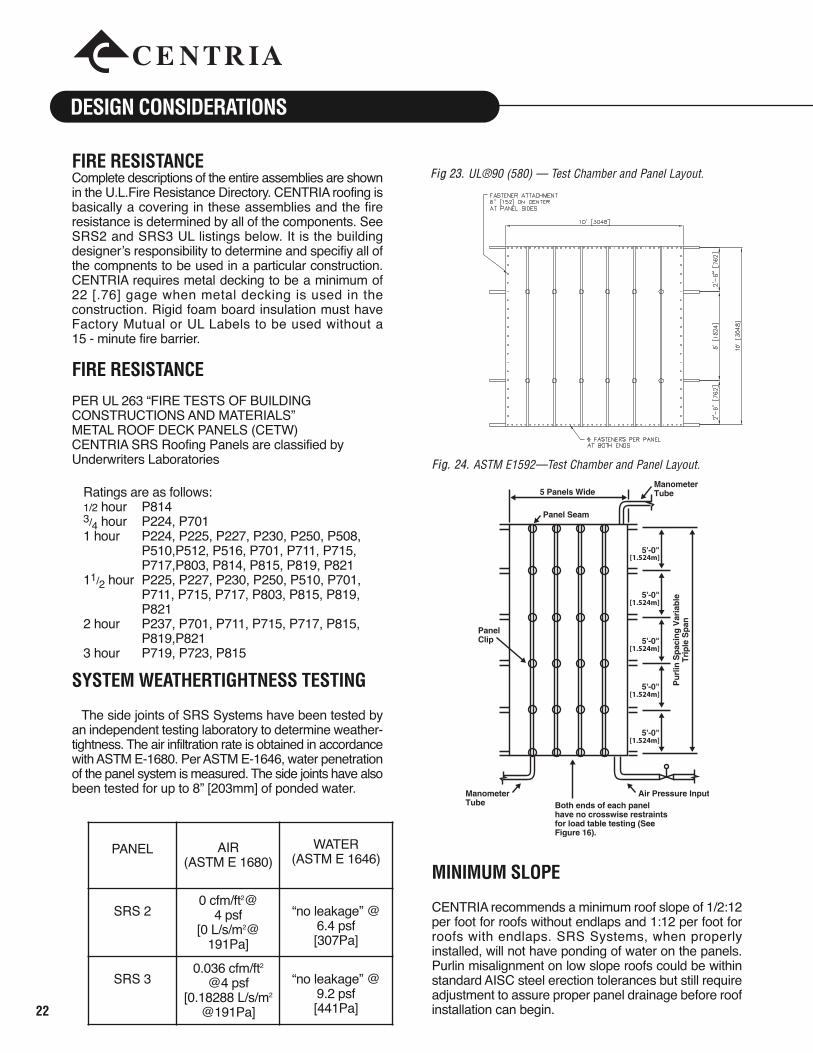
A minimum of five panels are tested. The purlin
spacing can be adjusted to any span condition. Air
pressure applied to the assembly is indicated by
manometers.
Dial gages record panel rib deflection and can
indicate a concealed clip failure. A rule is used to
measure pan deflection.
None of the panel ends have fasteners which can
limit pan deflection. Full pan deflection can occur
within 10' of a restricted panel end.
Approximately 100 psf [4.78kPa] load shown. Pan
deflection as much as 8" [203mm] will occur on an
18" [457mm] panel. Note that the vertical legs are
approaching a horizontal position. This test procedure
is the only method to determine the clip strength
under load.
Figure 22. CENTRIA Uplift Test Procedures.
16
SRS 2 — PANEL SECTION PROPERTIESPanelProfile
SRS 2-1.5
SRS 2-1.33
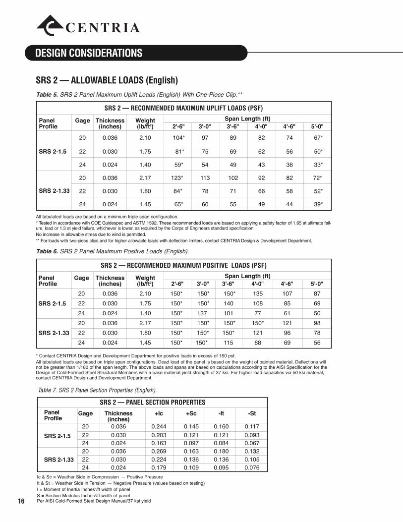
Table 7. SRS 2 Panel Section Properties (English).
Gage Thickness +Ic +Sc -It -St(inches)
20 0.036 0.244 0.145 0.160 0.117
22 0.030 0.203 0.121 0.121 0.093
24 0.024 0.163 0.097 0.084 0.067
20 0.036 0.269 0.163 0.180 0.132
22 0.030 0.224 0.136 0.136 0.105
24 0.024 0.179 0.109 0.095 0.076
Ic & Sc = Weather Side in Compression — Positive Pressure
It & St = Weather Side in Tension — Negative Pressure (values based on testing)
I = Moment of Inertia Inches4/ft width of panel
S = Section Modulus Inches3/ft width of panelPer AISI Cold-Formed Steel Design Manual/37 ksi yield
SRS 2 — ALLOWABLE LOADS (English)Table 5. SRS 2 Panel Maximum Uplift Loads (English) With One-Piece Clip.**
Table 6. SRS 2 Panel Maximum Positive Loads (English).
Gage Thickness Weight(inches) (lb/ft2) 2'-6" 3'-0" 3'-6" 4'-0" 4'-6" 5'-0"
20 0.036 2.10 104* 97 89 82 74 67*
22 0.030 1.75 81* 75 69 62 56 50*
24 0.024 1.40 59* 54 49 43 38 33*
20 0.036 2.17 123* 113 102 92 82 72*
22 0.030 1.80 84* 78 71 66 58 52*
24 0.024 1.45 65* 60 55 49 44 39*
SRS 2 — RECOMMENDED MAXIMUM UPLIFT LOADS (PSF)
Span Length (ft)PanelProfile
SRS 2-1.5
SRS 2-1.33
Gage Thickness Weight(inches) (lb/ft2) 2'-6" 3'-0" 3'-6" 4'-0" 4'-6" 5'-0"
20 0.036 2.10 150* 150* 150* 135 107 87
22 0.030 1.75 150* 150* 140 108 85 69
24 0.024 1.40 150* 137 101 77 61 50
20 0.036 2.17 150* 150* 150* 150* 121 98
22 0.030 1.80 150* 150* 150* 121 96 78
24 0.024 1.45 150* 150* 115 88 69 56
SRS 2 — RECOMMENDED MAXIMUM POSITIVE LOADS (PSF)
Span Length (ft)PanelProfile
SRS 2-1.5
SRS 2-1.33
All tabulated loads are based on a minimum triple span configuration.
* Tested in accordance with COE Guidespec and ASTM 1592. These recommended loads are based on applying a safety factor of 1.65 at ultimate fail-ure, load or 1.3 at yield failure, whichever is lower, as required by the Corps of Engineers standard specification.
No increase in allowable stress due to wind is permitted.
** For loads with two-piece clips and for higher allowable loads with deflection limiters, contact CENTRIA Design & Development Department.
* Contact CENTRIA Design and Development Department for positive loads in excess of 150 psf.
All tabulated loads are based on triple span configurations. Dead load of the panel is based on the weight of painted material. Deflections willnot be greater than 1/180 of the span length. The above loads and spans are based on calculations according to the AISI Specification for theDesign of Cold-Formed Steel Structural Members with a base material yield strength of 37 ksi. For higher load capacities via 50 ksi material,contact CENTRIA Design and Development Department.
DESIGN CONSIDERATIONS
17
DESIGN CONSIDERATIONS
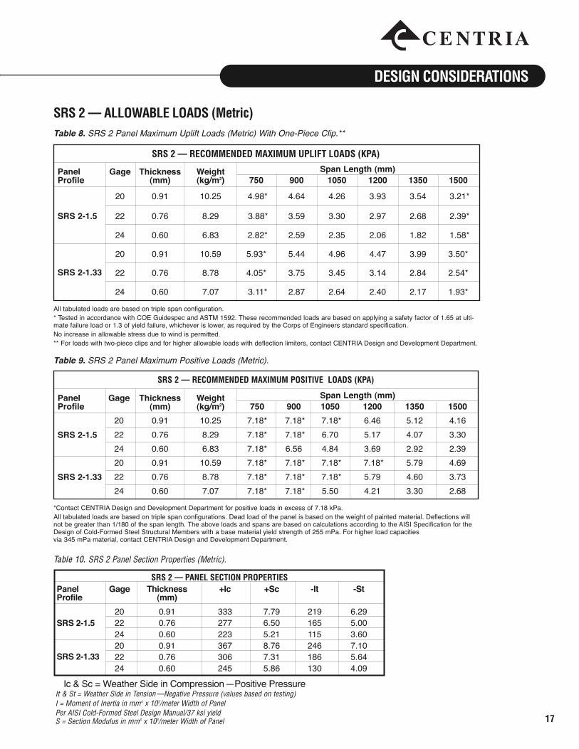
Table 10. SRS 2 Panel Section Properties (Metric).
Gage Thickness +Ic +Sc -It -St(mm)
20 0.91 333 7.79 219 6.29
22 0.76 277 6.50 165 5.00
24 0.60 223 5.21 115 3.60
20 0.91 367 8.76 246 7.10
22 0.76 306 7.31 186 5.64
24 0.60 245 5.86 130 4.09
SRS 2 — PANEL SECTION PROPERTIESPanelProfile
SRS 2-1.5
SRS 2-1.33
Ic & Sc = Weather Side in Compression—Positive PressureIt & St = Weather Side in Tension—Negative Pressure (values based on testing)I = Moment of Inertia in mm4 x 103/meter Width of PanelPer AISI Cold-Formed Steel Design Manual/37 ksi yieldS = Section Modulus in mm3 x 103/meter Width of Panel
SRS 2 — ALLOWABLE LOADS (Metric)Table 8. SRS 2 Panel Maximum Uplift Loads (Metric) With One-Piece Clip.**
Table 9. SRS 2 Panel Maximum Positive Loads (Metric).
Gage Thickness Weight(mm) (kg/m2) 750 900 1050 1200 1350 1500
20 0.91 10.25 7.18* 7.18* 7.18* 6.46 5.12 4.16
22 0.76 8.29 7.18* 7.18* 6.70 5.17 4.07 3.30
24 0.60 6.83 7.18* 6.56 4.84 3.69 2.92 2.39
20 0.91 10.59 7.18* 7.18* 7.18* 7.18* 5.79 4.69
22 0.76 8.78 7.18* 7.18* 7.18* 5.79 4.60 3.73
24 0.60 7.07 7.18* 7.18* 5.50 4.21 3.30 2.68
SRS 2 — RECOMMENDED MAXIMUM POSITIVE LOADS (KPA)
Span Length (mm)PanelProfile
SRS 2-1.5
SRS 2-1.33
All tabulated loads are based on triple span configuration.
* Tested in accordance with COE Guidespec and ASTM 1592. These recommended loads are based on applying a safety factor of 1.65 at ulti-mate failure load or 1.3 of yield failure, whichever is lower, as required by the Corps of Engineers standard specification.
No increase in allowable stress due to wind is permitted.
** For loads with two-piece clips and for higher allowable loads with deflection limiters, contact CENTRIA Design and Development Department.
*Contact CENTRIA Design and Development Department for positive loads in excess of 7.18 kPa.
All tabulated loads are based on triple span configurations. Dead load of the panel is based on the weight of painted material. Deflections willnot be greater than 1/180 of the span length. The above loads and spans are based on calculations according to the AISI Specification for theDesign of Cold-Formed Steel Structural Members with a base material yield strength of 255 mPa. For higher load capacities via 345 mPa material, contact CENTRIA Design and Development Department.
Gage Thickness Weight(mm) (kg/m2) 750 900 1050 1200 1350 1500
20 0.91 10.25 4.98* 4.64 4.26 3.93 3.54 3.21*
22 0.76 8.29 3.88* 3.59 3.30 2.97 2.68 2.39*
24 0.60 6.83 2.82* 2.59 2.35 2.06 1.82 1.58*
20 0.91 10.59 5.93* 5.44 4.96 4.47 3.99 3.50*
22 0.76 8.78 4.05* 3.75 3.45 3.14 2.84 2.54*
24 0.60 7.07 3.11* 2.87 2.64 2.40 2.17 1.93*
SRS 2 — RECOMMENDED MAXIMUM UPLIFT LOADS (KPA)
Span Length (mm)PanelProfile
SRS 2-1.5
SRS 2-1.33
18
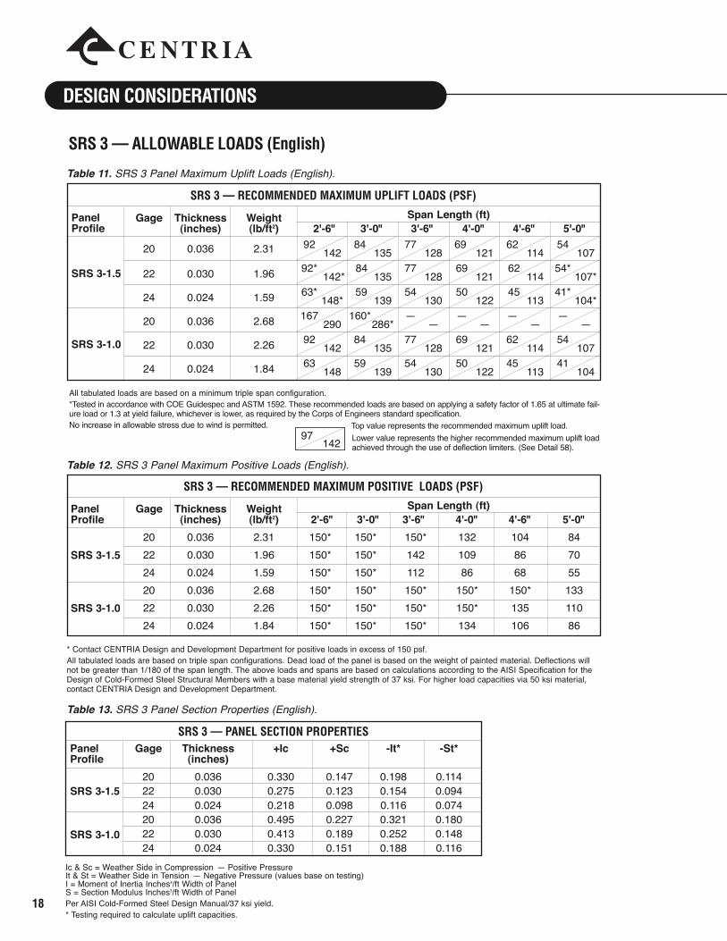
92 84 77 69 62 54
92* 84 77 69 62 54*
63* 59 54 50 45 41*
167 160* — — — —
92 84 77 69 62 54
63 59 54 50 45 41
Gage Thickness Weight(inches) (lb/ft2) 2'-6" 3'-0" 3'-6" 4'-0" 4'-6" 5'-0"
20 0.036 2.31
22 0.030 1.96
24 0.024 1.59
20 0.036 2.68
22 0.030 2.26
24 0.024 1.84
Gage Thickness Weight(inches) (lb/ft2) 2'-6" 3'-0" 3'-6" 4'-0" 4'-6" 5'-0"
20 0.036 2.31 150* 150* 150* 132 104 84
22 0.030 1.96 150* 150* 142 109 86 70
24 0.024 1.59 150* 150* 112 86 68 55
20 0.036 2.68 150* 150* 150* 150* 150* 133
22 0.030 2.26 150* 150* 150* 150* 135 110
24 0.024 1.84 150* 150* 150* 134 106 86
SRS 3 — RECOMMENDED MAXIMUM POSITIVE LOADS (PSF)
Span Length (ft)PanelProfile
SRS 3-1.5
SRS 3-1.0
* Contact CENTRIA Design and Development Department for positive loads in excess of 150 psf.
All tabulated loads are based on triple span configurations. Dead load of the panel is based on the weight of painted material. Deflections willnot be greater than 1/180 of the span length. The above loads and spans are based on calculations according to the AISI Specification for theDesign of Cold-Formed Steel Structural Members with a base material yield strength of 37 ksi. For higher load capacities via 50 ksi material,contact CENTRIA Design and Development Department.
142 135 128 121 114 107
142* 135 128 121 114 107*
148* 139 130 122 113 104*
290 286* — — — —
142 135 128 121 114 107
148 139 130 122 113 104
SRS 3 — ALLOWABLE LOADS (English)
Table 11. SRS 3 Panel Maximum Uplift Loads (English).
Table 12. SRS 3 Panel Maximum Positive Loads (English).
Table 13. SRS 3 Panel Section Properties (English).
SRS 3 — RECOMMENDED MAXIMUM UPLIFT LOADS (PSF)
Span Length (ft)
Gage Thickness +Ic +Sc -It* -St*(inches)
20 0.036 0.330 0.147 0.198 0.114
22 0.030 0.275 0.123 0.154 0.094
24 0.024 0.218 0.098 0.116 0.074
20 0.036 0.495 0.227 0.321 0.180
22 0.030 0.413 0.189 0.252 0.148
24 0.024 0.330 0.151 0.188 0.116
SRS 3 — PANEL SECTION PROPERTIESPanelProfile
SRS 3-1.5
SRS 3-1.0
All tabulated loads are based on a minimum triple span configuration.
*Tested in accordance with COE Guidespec and ASTM 1592. These recommended loads are based on applying a safety factor of 1.65 at ultimate fail-ure load or 1.3 at yield failure, whichever is lower, as required by the Corps of Engineers standard specification.
No increase in allowable stress due to wind is permitted.
Ic & Sc = Weather Side in Compression — Positive PressureIt & St = Weather Side in Tension — Negative Pressure (values base on testing)I = Moment of Inertia Inches4/ft Width of PanelS = Section Modulus Inches3/ft Width of Panel
Per AISI Cold-Formed Steel Design Manual/37 ksi yield.
* Testing required to calculate uplift capacities.
Lower value represents the higher recommended maximum uplift loadachieved through the use of deflection limiters. (See Detail 58).
Top value represents the recommended maximum uplift load.
97142
DESIGN CONSIDERATIONS
PanelProfile
SRS 3-1.5
SRS 3-1.0
19
DESIGN CONSIDERATIONS
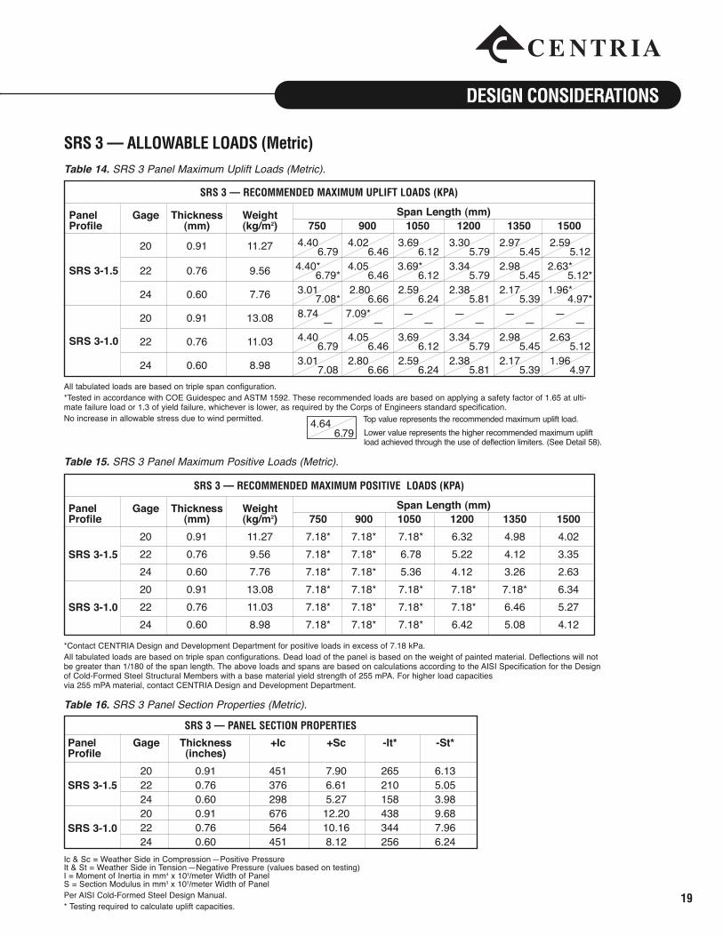
6.79 6.46 6.12 5.79 5.45 5.12
6.79* 6.46 6.12 5.79 5.45 5.12*
7.08* 6.66 6.24 5.81 5.39 4.97*
— — — — — —
6.79 6.46 6.12 5.79 5.45 5.12
7.08 6.66 6.24 5.81 5.39 4.97
SRS 3 — ALLOWABLE LOADS (Metric)Table 14. SRS 3 Panel Maximum Uplift Loads (Metric).
Table 15. SRS 3 Panel Maximum Positive Loads (Metric).
Table 16. SRS 3 Panel Section Properties (Metric).
Gage Thickness Weight(mm) (kg/m2) 750 900 1050 1200 1350 1500
20 0.91 11.27 7.18* 7.18* 7.18* 6.32 4.98 4.02
22 0.76 9.56 7.18* 7.18* 6.78 5.22 4.12 3.35
24 0.60 7.76 7.18* 7.18* 5.36 4.12 3.26 2.63
20 0.91 13.08 7.18* 7.18* 7.18* 7.18* 7.18* 6.34
22 0.76 11.03 7.18* 7.18* 7.18* 7.18* 6.46 5.27
24 0.60 8.98 7.18* 7.18* 7.18* 6.42 5.08 4.12
SRS 3 — RECOMMENDED MAXIMUM POSITIVE LOADS (KPA)
Span Length (mm)PanelProfile
SRS 3-1.5
SRS 3-1.0
Gage Thickness +Ic +Sc -It* -St*(inches)
20 0.91 451 7.90 265 6.13
22 0.76 376 6.61 210 5.05
24 0.60 298 5.27 158 3.98
20 0.91 676 12.20 438 9.68
22 0.76 564 10.16 344 7.96
24 0.60 451 8.12 256 6.24
SRS 3 — PANEL SECTION PROPERTIES
PanelProfile
SRS 3-1.5
SRS 3-1.0
All tabulated loads are based on triple span configuration.
*Tested in accordance with COE Guidespec and ASTM 1592. These recommended loads are based on applying a safety factor of 1.65 at ulti-mate failure load or 1.3 of yield failure, whichever is lower, as required by the Corps of Engineers standard specification.
No increase in allowable stress due to wind permitted.
*Contact CENTRIA Design and Development Department for positive loads in excess of 7.18 kPa.
All tabulated loads are based on triple span configurations. Dead load of the panel is based on the weight of painted material. Deflections will notbe greater than 1/180 of the span length. The above loads and spans are based on calculations according to the AISI Specification for the Designof Cold-Formed Steel Structural Members with a base material yield strength of 255 mPA. For higher load capacities via 255 mPA material, contact CENTRIA Design and Development Department.
Ic & Sc = Weather Side in Compression—Positive PressureIt & St = Weather Side in Tension—Negative Pressure (values based on testing)I = Moment of Inertia in mm4 x 103/meter Width of PanelS = Section Modulus in mm3 x 103/meter Width of Panel
Per AISI Cold-Formed Steel Design Manual.
* Testing required to calculate uplift capacities.
Gage Thickness Weight(mm) (kg/m2) 750 900 1050 1200 1350 1500
20 0.91 11.27
22 0.76 9.56
24 0.60 7.76
20 0.91 13.08
22 0.76 11.03
24 0.60 8.98
4.40 4.02 3.69 3.30 2.97 2.59
4.40* 4.05 3.69* 3.34 2.98 2.63*
3.01 2.80 2.59 2.38 2.17 1.96*
8.74 7.09* — — — —
4.40 4.05 3.69 3.34 2.98 2.63
3.01 2.80 2.59 2.38 2.17 1.96
SRS 3 — RECOMMENDED MAXIMUM UPLIFT LOADS (KPA)
Span Length (mm)PanelProfile
SRS 3-1.5
SRS 3-1.0
Lower value represents the higher recommended maximum upliftload achieved through the use of deflection limiters. (See Detail 58).
Top value represents the recommended maximum uplift load.4.646.79
20
DESIGN CONSIDERATIONS
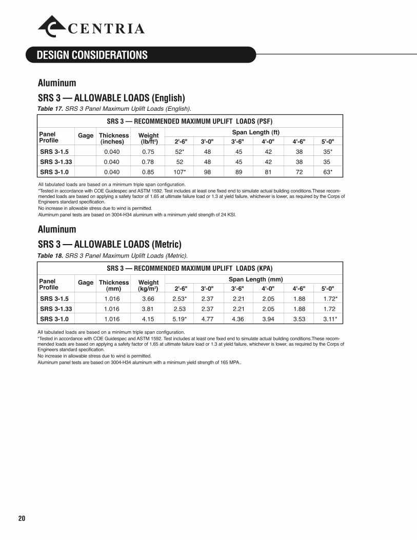
Gage Thickness Weight(inches) (lb/ft2) 2'-6" 3'-0" 3'-6" 4'-0" 4'-6" 5'-0"
SRS 3-1.5 0.040 0.75 52* 48 45 42 38 35*
SRS 3-1.33 0.040 0.78 52 48 45 42 38 35
SRS 3-1.0 0.040 0.85 107* 98 89 81 72 63*
SRS 3 — RECOMMENDED MAXIMUM UPLIFT LOADS (PSF)
Span Length (ft)PanelProfile
Aluminum
SRS 3 — ALLOWABLE LOADS (English)Table 17. SRS 3 Panel Maximum Uplift Loads (English).
Gage Thickness Weight(mm) (kg/m2) 2'-6" 3'-0" 3'-6" 4'-0" 4'-6" 5'-0"
SRS 3-1.5 1.016 3.66 2.53* 2.37 2.21 2.05 1.88 1.72*
SRS 3-1.33 1.016 3.81 2.53 2.37 2.21 2.05 1.88 1.72
SRS 3-1.0 1.016 4.15 5.19* 4.77 4.36 3.94 3.53 3.11*
SRS 3 — RECOMMENDED MAXIMUM UPLIFT LOADS (KPA)
Span Length (mm)PanelProfile
Aluminum
SRS 3 — ALLOWABLE LOADS (Metric)Table 18. SRS 3 Panel Maximum Uplift Loads (Metric).
All tabulated loads are based on a minimum triple span configuration.
*Tested in accordance with COE Guidespec and ASTM 1592. Test includes at least one fixed end to simulate actual building conditions.These recom-mended loads are based on applying a safety factor of 1.65 at ultimate failure load or 1.3 at yield failure, whichever is lower, as required by the Corps ofEngineers standard specification.
No increase in allowable stress due to wind is permitted.
Aluminum panel tests are based on 3004-H34 aluminum with a minimum yield strength of 24 KSI.
All tabulated loads are based on a minimum triple span configuration.
*Tested in accordance with COE Guidespec and ASTM 1592. Test includes at least one fixed end to simulate actual building conditions.These recom-mended loads are based on applying a safety factor of 1.65 at ultimate failure load or 1.3 at yield failure, whichever is lower, as required by the Corps ofEngineers standard specification.
No increase in allowable stress due to wind is permitted.
Aluminum panel tests are based on 3004-H34 aluminum with a minimum yield strength of 165 MPA..
21
UNDERWRITERS LABORATORIES WINDUPLIFT CLASSIFICATIONPER UL® 580
CENTRIA panels have been tested by UL® and have a Class 90 Rating for all of the system components as listed in Table 19.
Comparison of ASTM E1592and UL® 90 (Test 580)
ASTM E1592 Test Significance (Fig. 24)
• Complies with AISI Cold-Formed Steel Design manual for determining structural performance
• Quantifies multiple span conditions• Used to develop negative load tables• Simulates field conditions • Permits variable purlin spacing• Provides accurate loading capacities of panel
components of a standing seam roof system• Test is run to ultimate failure
UL 580 CLASS 90 TEST SIGNIFICANCE (FIG. 23)
• Provides a comparative index of all types of roofassemblies with respect to uplift resistance
• Not intended to quantify load/span tables• Not intended to quantify roof performance in actual
field conditions• End restraints limit full pan deflection• Intended to represent field installations within
restraints of the test frame• Evaluates systems on pass/fail basis• Test is run to 105 psf [5.03kPa]
FACTORY MUTUAL WIND STORMCLASSIFICATION
22 [.76] gage SRS 3-1.5, is tested and approved for FM1-90 wind storm classification. Panel must be installedover minimum 16 [1.587] gage open framing or minimum22 [.76] gage steel deck. Maximum clip spacing of 4’-0”[1.219m].
20 [.91] gage SRS 3-1.0, is tested and approved for FM1-180 wind storm classification. Panel must be installedover minimum 14 [1.984] gage purlins. Maximum clipspacing of 4’-0” [1.219m-0].
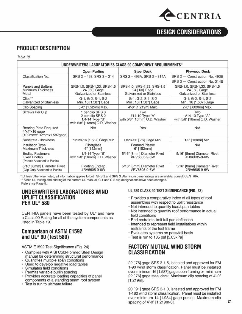
UNDERWRITERS LABORATORIES CLASS 90 COMPONENT REQUIREMENTS*
Open Purlins Steel Deck Plywood Deck
Classification No. SRS 2 – 493, SRS 3 – 314 SRS 2 – 493A, SRS 3 – 314A SRS 2 — Construction No. 493B
SRS 3 — Construction No. 314B
Panels and Battens SRS-1.0, SRS-1.33, SRS-1.5 SRS-1.0, SRS-1.33, SRS-1.5 SRS-1.0, SRS-1.33, SRS-1.5Minimum Thickness 24 [.60] Gage 24 [.60] Gage 24 [.60] GageMetal Galvanized or Stainless Galvanized or Stainless Galvanized or Stainless
Clips** G-1, G-2, S-1, S-2 G-1, G-2, S-1, S-2 G-1, G-2, S-1, S-2Galvanized or Stainless Min. 16 [1.587] Gage Min . 16 [1.587] Gage Min . 16 [1.587] Gage
Clip Spacing 5'-0" [1.524m] Max. 4'-0" [1.219m] Max. 2’-0” [.6096m] Max.
Screws Per Clip 1 per clip SRS 3 Two Two2 per clip SRS 2 #14-10 Type “A” #14-10 Type “A”1/4-14 Type “B” with 5/8" [16mm] O.D. Washer with 5/8" [16mm] O.D. Washer
with 5/8" [16mm] O.D. Washer
Bearing Plate Required N/A Yes N/A4"x4"x16 gage[102mmx102mmx1.587gage]
Substrate -Thickness Purlins-16 [1.587] Gage Min. Deck-22 [.76] Gage Min. 1/2” [13mm] Min.
Insulation Type Fiberglass Foamed Plastic N/AMaximum Thickness 6" [152mm] 6" [152mm]
Endlap Fasteners 1/4-14 Type “B” 5/16" [8mm] Diameter Rivet 5/16" [8mm] Diameter RivetFixed Endlap with 5/8" [16mm] O.D. Washer #RV6605-9-6W #RV6605-9-6W(Panels Attached to Purlin)
5/16" [8mm] Diameter Rivet Floating Endlap 5/16" [8mm] Diameter Rivet 5/16" [8mm] Diameter Rivet(Clip Only Attached to Purlin) #RV6605-9-6W #RV6605-9-6W #RV6605-9-6W
Table 19.
* Unless otherwise noted, all information applies to both SRS 2 and SRS 3. Aluminum panel ratings are available, consult CENTRIA.** Since UL testing and printing of the current UL manual, C-1 and C-2 clip designations have been changed.Reference Page 5.
PRODUCT DESCRIPTION
DESIGN CONSIDERATIONS
22
MINIMUM SLOPE
CENTRIA recommends a minimum roof slope of 1/2:12per foot for roofs without endlaps and 1:12 per foot forroofs with endlaps. SRS Systems, when properlyinstalled, will not have ponding of water on the panels.Purlin misalignment on low slope roofs could be withinstandard AISC steel erection tolerances but still requireadjustment to assure proper panel drainage before roofinstallation can begin.
FIRE RESISTANCEComplete descriptions of the entire assemblies are shownin the U.L.Fire Resistance Directory. CENTRIA roofing isbasically a covering in these assemblies and the fireresistance is determined by all of the components. SeeSRS2 and SRS3 UL listings below. It is the buildingdesigner’s responsibility to determine and specifiy all ofthe compnents to be used in a particular construction.CENTRIA requires metal decking to be a minimum of22 [.76] gage when metal decking is used in theconstruction. Rigid foam board insulation must haveFactory Mutual or UL Labels to be used without a15 - minute fire barrier.
FIRE RESISTANCE
PER UL 263 “FIRE TESTS OF BUILDING CONSTRUCTIONS AND MATERIALS” METAL ROOF DECK PANELS (CETW)CENTRIA SRS Roofing Panels are classified byUnderwriters Laboratories
Ratings are as follows:1/2 hour P8143/4 hour P224, P7011 hour P224, P225, P227, P230, P250, P508,
P510,P512, P516, P701, P711, P715, P717,P803, P814, P815, P819, P821
11/2 hour P225, P227, P230, P250, P510, P701, P711, P715, P717, P803, P815, P819, P821
2 hour P237, P701, P711, P715, P717, P815, P819,P821
3 hour P719, P723, P815
SYSTEM WEATHERTIGHTNESS TESTING
The side joints of SRS Systems have been tested byan independent testing laboratory to determine weather-tightness. The air infiltration rate is obtained in accordancewith ASTM E-1680. Per ASTM E-1646, water penetrationof the panel system is measured. The side joints have alsobeen tested for up to 8” [203mm] of ponded water.
[1.524m]
[1.524m]
[1.524m]
[1.524m]
[1.524m]
Fig. 24. ASTM E1592—Test Chamber and Panel Layout.
Fig 23. UL®90 (580) — Test Chamber and Panel Layout.
PANEL AIR (ASTM E 1680)
WATER(ASTM E 1646)
SRS 20 cfm/ft2@
4 psf[0 L/s/m2@
191Pa]
“no leakage” @6.4 psf[307Pa]
SRS 30.036 cfm/ft2
@4 psf[0.18288 L/s/m2
@191Pa]
“no leakage” @9.2 psf[441Pa]
DESIGN CONSIDERATIONS
23
DESIGN CONSIDERATIONS
B.Fixing line requirements can vary from job to jobbased on sheet lengths, panel color, perimeter details,substrate type, etc. However, as a general rule, fixingpoints should be in a straight line perpendicular to thepanel length.Other general recommendations as theyrelate to fixing line locations are as follows:
1. Fixing lines should be at gutter and valley detailsbecause of the high performance weather tightness typically required at these details.
2. Panels which meet the following length limitations do not require the use of a floating ridge and hip cap detail. The minimal linear expansion in the sheet is relieved by slight distortion and rotation of the one-piece ridge or hip cap and closure assemblies.A) Steel panels 30’-0” [9.144m] long or lessB) Aluminum panels 15”-0” [4.572m] long or lessC) Stainless steel panels 20’-0” [6.096m] long or less
3. Establish fixing lines at the eaves and use a floating hip and ridge cap for the following conditions (unbalanced design):A) Steel panels under 75’-0” [22.86] longB) Aluminum panels under 40’-0” [12.192m] longC) Stainless steel panels under 50’-0” [15.24m] long
4. Establish fixing lines at mid-length of sheet and use floating eave, ridge and hip details to minimize total movement at panel ends for the following conditions (balanced design)A) Steel panels over 75’-0” [22.86m] longB) Aluminum panels over 40’-0” [12.192m] longC) Stainless steel panels over 50’-0” [15.24m] long
When utilizing mid-span or balanced design, two rowsof adjacent fixing lines are required for sheet lengthsfrom 75’ [22.86m] to 150’ [45.72m] and three rows forsheet lengths over 150’ [45.72m].
PURLIN DESIGN CONSIDERATIONS
I. Purlin Erection TolerancesOn many structures, it is general practice to specify thatframing tolerances be in accordance with AISC code ofstandard practice. However, since SRS panels havenon-ribbed flats which in most cases are 18” [457mm]wide, this specified tolerance is generally not sufficient toinsure SRS panel flatness due to the fact that purlinmisalignment often induces rippling and/or oil canningin wide flat products.A.The following purlin erection tolerances are
recommended.1. Maximum out-of-plane deviation should be
limited to ± 3/16” [5mm] from the control with a maximum deviation of 1/8” [3mm] between adjacent clip locations or L/500,whichever is less
2. Before panels are installed to the sub-framing system, it is imperative that purlin erection tolerances be checked. If any discrepancies exist, then all panel erection should be haulted until the proper purlin tolerances are established.Purlins which are out of tolerance can lead to restricted thermal movement of the panels.
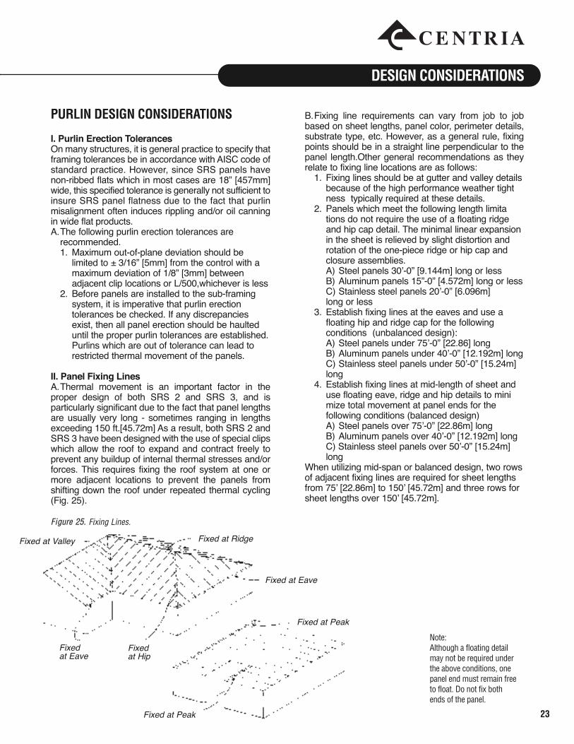
II. Panel Fixing LinesA.Thermal movement is an important factor in theproper design of both SRS 2 and SRS 3, and isparticularly significant due to the fact that panel lengthsare usually very long - sometimes ranging in lengthsexceeding 150 ft.[45.72m] As a result, both SRS 2 andSRS 3 have been designed with the use of special clipswhich allow the roof to expand and contract freely toprevent any buildup of internal thermal stresses and/orforces. This requires fixing the roof system at one ormore adjacent locations to prevent the panels fromshifting down the roof under repeated thermal cycling(Fig. 25).
Figure 25. Fixing Lines.
Fixed at Peak
Fixed at Hip
Fixed at Eave
Fixed at Valley Fixed at Ridge
Fixed at Eave
Fixed at Peak
Note:Although a floating detailmay not be required underthe above conditions, onepanel end must remain freeto float. Do not fix bothends of the panel.
24
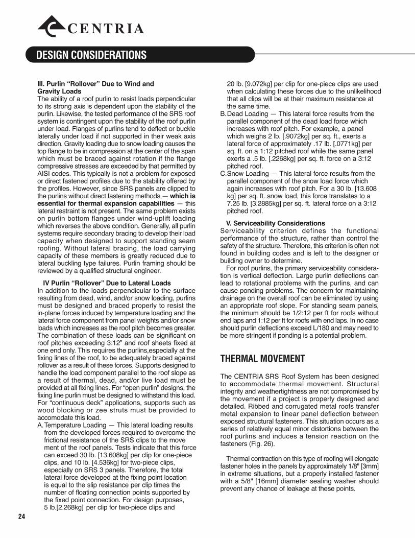
III. Purlin “Rollover” Due to Wind and Gravity LoadsThe ability of a roof purlin to resist loads perpendicularto its strong axis is dependent upon the stability of thepurlin. Likewise, the tested performance of the SRS roofsystem is contingent upon the stability of the roof purlinunder load. Flanges of purlins tend to deflect or bucklelaterally under load if not supported in their weak axisdirection. Gravity loading due to snow loading causes thetop flange to be in compression at the center of the spanwhich must be braced against rotation if the flangecompressive stresses are exceeded by that permitted byAISI codes. This typically is not a problem for exposedor direct fastened profiles due to the stability offered bythe profiles. However, since SRS panels are clipped tothe purlins without direct fastening methods — which isessential for thermal expansion capabilities — thislateral restraint is not present. The same problem existson purlin bottom flanges under wind-uplift loadingwhich reverses the above condition. Generally, all purlinsystems require secondary bracing to develop their loadcapacity when designed to support standing seamroofing. Without lateral bracing, the load carryingcapacity of these members is greatly reduced due tolateral buckling type failures. Purlin framing should bereviewed by a qualified structural engineer.
IV Purlin “Rollover” Due to Lateral LoadsIn addition to the loads perpendicular to the surfaceresulting from dead, wind, and/or snow loading, purlinsmust be designed and braced properly to resist thein-plane forces induced by temperature loading and thelateral force component from panel weights and/or snowloads which increases as the roof pitch becomes greater.The combination of these loads can be significant onroof pitches exceeding 3:12” and roof sheets fixed atone end only. This requires the purlins,especially at thefixing lines of the roof, to be adequately braced againstrollover as a result of these forces. Supports designed tohandle the load component parallel to the roof slope asa result of thermal, dead, and/or live load must beprovided at all fixing lines. For “open purlin” designs, thefixing line purlin must be designed to withstand this load.For “continuous deck” applications, supports such aswood blocking or zee struts must be provided toaccomodate this load.A.Temperature Loading — This lateral loading results
from the developed forces required to overcome thefrictional resistance of the SRS clips to the movement of the roof panels. Tests indicate that this forcecan exceed 30 lb. [13.608kg] per clip for one-piece clips, and 10 lb. [4.536kg] for two-piece clips, especially on SRS 3 panels. Therefore, the total lateral force developed at the fixing point location is equal to the slip resistance per clip times the number of floating connection points supported by the fixed point connection. For design purposes, 5 lb.[2.268kg] per clip for two-piece clips and
20 lb. [9.072kg] per clip for one-piece clips are usedwhen calculating these forces due to the unlikelihoodthat all clips will be at their maximum resistance at the same time.
B.Dead Loading — This lateral force results from the parallel component of the dead load force which increases with roof pitch. For example, a panel which weighs 2 lb. [.9072kg] per sq. ft., exerts a lateral force of approximately .17 lb. [.0771kg] per sq. ft. on a 1:12 pitched roof while the same panel exerts a .5 lb. [.2268kg] per sq. ft. force on a 3:12 pitched roof.
C.Snow Loading — This lateral force results from the parallel component of the snow load force which again increases with roof pitch. For a 30 lb. [13.608 kg] per sq. ft. snow load, this force translates to a 7.25 lb. [3.2885kg] per sq. ft. lateral force on a 3:12 pitched roof.
V. Serviceability ConsiderationsServiceability criterion defines the functionalperformance of the structure, rather than control thesafety of the structure. Therefore, this criterion is often notfound in building codes and is left to the designer orbuilding owner to determine.
For roof purlins, the primary serviceability considera-tion is vertical deflection. Large purlin deflections canlead to rotational problems with the purlins, and cancause ponding problems. The concern for maintainingdrainage on the overall roof can be eliminated by usingan appropriate roof slope. For standing seam panels,the minimum should be 1/2:12 per ft for roofs withoutend laps and 1:12 per ft for roofs with end laps. In no caseshould purlin deflections exceed L/180 and may need tobe more stringent if ponding is a potential problem.
THERMAL MOVEMENT
The CENTRIA SRS Roof System has been designedto accommodate thermal movement. Structuralintegrity and weathertightness are not compromised bythe movement if a project is properly designed anddetailed. Ribbed and corrugated metal roofs transfermetal expansion to linear panel deflection betweenexposed structural fasteners. This situation occurs as aseries of relatively equal minor distortions between theroof purlins and induces a tension reaction on thefasteners (Fig. 26).
Thermal contraction on this type of roofing will elongatefastener holes in the panels by approximately 1/8" [3mm]in extreme situations, but a properly installed fastenerwith a 5/8" [16mm] diameter sealing washer shouldprevent any chance of leakage at these points.
DESIGN CONSIDERATIONS
25
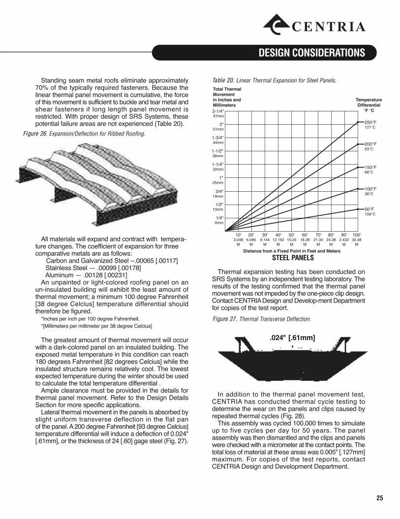
Thermal expansion testing has been conducted onSRS Systems by an independent testing laboratory. Theresults of the testing confirmed that the thermal panelmovement was not impeded by the one-piece clip design.Contact CENTRIA Design and Develop-ment Departmentfor copies of the test report.
In addition to the thermal panel movement test,CENTRIA has conducted thermal cycle testing todetermine the wear on the panels and clips caused byrepeated thermal cycles (Fig. 28).
This assembly was cycled 100,000 times to simulateup to five cycles per day for 50 years. The panelassembly was then dismantled and the clips and panelswere checked with a micrometer at the contact points. Thetotal loss of material at these areas was 0.005" [.127mm]maximum. For copies of the test reports, contactCENTRIA Design and Development Department.
.024" [.61mm]
Table 20. Linear Thermal Expansion for Steel Panels.
2-1/4"
57mm
2"
51mm
1-3/4"
44mm
1-1/2"
38mm
1-1/4"
32mm
1"
25mm
3/4"
19mm
1/2"
13mm
1/4"
6mm
10'
3.048
M
20'
6.096
M
30'
9.144
M
40'
12.192
M
50'
15.24
M
60'
18.28
M
70'
21.34
M
80'
24.38
M
90'
2.432
M
100'
30.48
M
250°F
121°C
200°F
93°C
150°F
66°C
100°F
38°C
50°F
106°C
Temperature
Differential
°F °C
Total Thermal
Movement
in Inches and
Millimeters
Distance from a Fixed Point in Feet and Meters
STEEL PANELS
Standing seam metal roofs eliminate approximately70% of the typically required fasteners. Because thelinear thermal panel movement is cumulative, the forceof this movement is sufficient to buckle and tear metal andshear fasteners if long length panel movement isrestricted. With proper design of SRS Systems, thesepotential failure areas are not experienced (Table 20).
All materials will expand and contract with tempera-ture changes. The coefficient of expansion for threecomparative metals are as follows:
Carbon and Galvanized Steel --.00065 [.00117]Stainless Steel — .00099 [.00178]Aluminum — .00128 [.00231]
An unpainted or light-colored roofing panel on anun-insulated building will exhibit the least amount ofthermal movement; a minimum 100 degree Fahrenheit[38 degree Celcius] temperature differential shouldtherefore be figured.
*Inches per inch per 100 degree Fahrenheit.
*[Millimeters per millimeter per 38 degree Celcius]
The greatest amount of thermal movement will occurwith a dark-colored panel on an insulated building. Theexposed metal temperature in this condition can reach180 degrees Fahrenheit [82 degrees Celcius] while theinsulated structure remains relatively cool. The lowestexpected temperature during the winter should be usedto calculate the total temperature differential .
Ample clearance must be provided in the details forthermal panel movement. Refer to the Design DetailsSection for more specific applications.
Lateral thermal movement in the panels is absorbed byslight uniform transverse deflection in the flat pan of the panel. A 200 degree Fahrenheit [93 degree Celcius]temperature differential will induce a deflection of 0.024"[.61mm], or the thickness of 24 [.60] gage steel (Fig. 27).
Figure 26. Expansion/Deflection for Ribbed Roofing.
DESIGN CONSIDERATIONS
Figure 27. Thermal Transverse Deflection.
26
DESIGN CONSIDERATIONS
If additional thermal performance is required, a dropbasket insulation system suspended from the purlinscan be used.
Rigid foam board insulation that is 2” [51mm] thick willprovide a “U” value of approximately 0.077 BTU/Hr•Ft2•˚F[.437 w/m2 •˚C]. Consult insurance authorities andbuilding codes concerning approved application of thisinsulation. Rigid board foam insulation must have a min-imum density of 2.0 PCF, a minimum compressivestrength of 20 PSI and a 6”[152mm] maximum thick-ness with a factory mutual or UL approval.
Thermal breaks are required between the roofingsystem and the structural framing when insulation isplaced between purlins. As in metal sash systems, theexterior metal must be isolated from interior metal byusing a “thermal break” to prevent “through-metalconductance”. Ignoring the need for thermal isolationmay result in frost lines or condensation inside thebuilding.
ROOF SPACE VENTILATION
When reroofing an existing building with an SRSSystem or if a new building design has an “attic space”between the ceiling and the new roof, adequateventilation is required to prevent condensation. The totalnet vent area should equal 1/300 of the building roofarea at the eave line (1/150 in humid climates). Walllouvers or perforated soffits spaced uniformly arerecommended to allow for maximum air movement.
Example:
Roof Area at Eave = 10,000 square feet [929.03m2].
Vent area required 10,000/300 = 33-1/3 square feet [3.1m2] of net free area of wall louvers or perforated soffit and 33-1/3 square feet [3.1m2] of the net free area is required at the high point of the roof.
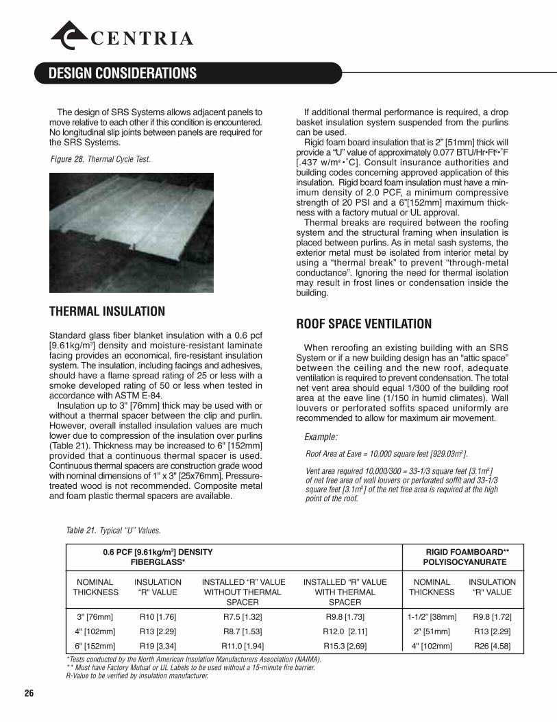
The design of SRS Systems allows adjacent panels tomove relative to each other if this condition is encountered.No longitudinal slip joints between panels are required forthe SRS Systems.
THERMAL INSULATION
Standard glass fiber blanket insulation with a 0.6 pcf[9.61kg/m3] density and moisture-resistant laminatefacing provides an economical, fire-resistant insulationsystem. The insulation, including facings and adhesives,should have a flame spread rating of 25 or less with asmoke developed rating of 50 or less when tested inaccordance with ASTM E-84.
Insulation up to 3" [76mm] thick may be used with orwithout a thermal spacer between the clip and purlin.However, overall installed insulation values are muchlower due to compression of the insulation over purlins(Table 21). Thickness may be increased to 6" [152mm]provided that a continuous thermal spacer is used.Continuous thermal spacers are construction grade woodwith nominal dimensions of 1" x 3" [25x76mm]. Pressure-treated wood is not recommended. Composite metaland foam plastic thermal spacers are available.
Figure 28. Thermal Cycle Test.
*Tests conducted by the North American Insulation Manufacturers Association (NAIMA).** Must have Factory Mutual or UL Labels to be used without a 15-minute fire barrier.R-Value to be verified by insulation manufacturer.
0.6 PCF [9.61kg/m3] DENSITY RIGID FOAMBOARD**
FIBERGLASS* POLYISOCYANURATE
NOMINAL INSULATION INSTALLED “R” VALUE INSTALLED “R” VALUE NOMINAL INSULATIONTHICKNESS “R" VALUE WITHOUT THERMAL WITH THERMAL THICKNESS “R" VALUE
SPACER SPACER
3" [76mm] R10 [1.76] R7.5 [1.32] R9.8 [1.73] 1-1/2” [38mm] R9.8 [1.72]
4" [102mm] R13 [2.29] R8.7 [1.53] R12.0 [2.11] 2" [51mm] R13 [2.29]
6" [152mm] R19 [3.34] R11.0 [1.94] R15.3 [2.69] 4" [102mm] R26 [4.58]
Table 21. Typical “U” Values.
27
MOISTURE CONTROL
The space inside a building contains air with differentproperties from that of the air outside. This microclimateof different temperature and relative humidity is createdby the HVAC system and contained by one or moreelements of the roof, wall and floor that together arereferred to as the building envelope. As is the naturalorder of things, differences held in check by this envelopeattempt to lessen over time. Differences in temperatureresult in heat loss or gain. Likewise, differences in vaporpressure, or the weight of the water contained in air, arediminished by mechanisms of moisture-laden airmovement or vapor diffusion.
The need for proper envelope design to limit heattransfer, air filtration and vapor migration is as importantas the design of the building foundation. The result ofpoor design and installation can be considerable. Gapsor poor design of the air and/or vapor barrier can resultin significant amounts of water being absorbed by theinsulation or other hygroscopic materials in the roofconstruction through condensate collection to be relievedsome time later into the conditioned space as a drip or awaterfall. In cases as this, it is rare that sufficientforensic evidence is available to distinguish thiscondensate seepage from a roof rainwater leak.Nevertheless, the results are the same — callbacks andclaims.
CENTRIA’s position on roof installations using ourmaterial is simple. The proper design, specification andinstallation of air and vapor control materials incommercial buildings is the responsibility of the owner anddesign professional for the project. Although notimplicitly outlined in most model building and energycodes, CENTRIA requires evidence of their properaddress to limit damage to and provide warranty for anyinstalled system incorporating our roof and wallproducts. Improper attention to design and installationof either the air barrier or the vapor barrier may result incondensate formation and leakage, loss of insulationvalues, corrosion of the support system and/orCENTRIA product, and mold growth. such damage isgenerally not caused in any direct way by the roofcladding, and CENTRIA shall deny any such claims asnot relevant.
ROOF DRAINAGE SYSTEMS
The design of the Roof Drainage System is an essentialfactor in the total roofing system design. Gutter anddownspout sizing tables can be found in the SMACNAArchitectural Sheet Metal Manual.
CENTRIA standard downspouts are 4"x 4"[102x102mm] square, and should be spaced to drain amaximum of 50 feet [15.24m] of gutter. Smaller
downspouts should be avoided as they are moresusceptible to blockage by debris or ice. Decreasing thedownspout spacing or increasing the size to 4" x 6"[102x152mm] will increase the conductor capacity. Thestandard CENTRIA eave gutter design is based onSMACNA rectangular type gutter “Style F”.
The front edge of the gutter is lower than the backedge so that any overflow will spill over the front of thegutter. Typically, level gutters are preferred for aestheticsand simplicity in design. Gutters require expansion jointsspaced at a maximum of 50'-0" [15.24m].
Built-in eave gutters are less visible than standardexposed gutters. Designers specifying this type of guttershould be aware that leaks which may develop will resultin water flow directly into the building. Frozendownspouts below exterior soffits will also cause thesegutters to overflow. The front of the gutter must be aminimum of 1" [25mm] lower than the back edge of thegutter.
Valley gutters should be designed with overflowscuppers at the ends of the gutter. The bottom of thescupper should be approximately 2" [51mm] lower thanthe top of the gutter.
Built-in eave gutters or valley gutters should havemembrane liners or be fabricated from 20 [.91] gageminimum stainless steel. To insure watertightness,stainless steel must be shop-welded to the longestpractical shipping length and water-tested prior toshipping; field-assembled valley gutters without linersare prone to leak at the fastener locations and end joints.
SNOW COUNTRY PRECAUTIONS
This section is intended to provide the building designerwith recommended designs, details and precautions inregard to metal roofing and snow. The followinginformation is based on past experience and is notintended to be used as a complete reference for metalroofing and drainage designs for snow conditions. Thedesigner should consider local conditions, building shapeand other such factors in the final building design.
Metal roofing, particularly standing seam, will shedsnow from moderately to steeply sloped roofs. In heavysnow areas, steep sloped roofs (8:12 slopes andsteeper) are designed to shed snow to prevent roofoverloading. This snow typically slides from the roof in onelarge mass that can cause injury or property damage atbuilding entrances, pedestrian walkways and vehicleparking areas. Gabled ends or large dormers should bedesigned above building entrances and other areas(HVAC units at grade, loading docks, lower roofs, etc.)where sliding snow could cause injury or damage.
Snow will easily slide on standing seam roofs withslopes steeper than 1-1/2:12. Snowguards arerecommended to prevent ice and snow movement.
DESIGN CONSIDERATIONS
28
Designer nOTe: snowguards are intended tokeep snow and ice in place until the snow and icemelts or evaporates. snowguards CAnnOT restrainthe forces produced when snow moves down a roof.
CENTRIA recommends use of the S-5! Color-GardTM
snow retention system for use in conjunction with SRS2 and SRS 3 roof systems. Use S-5-T clamps by S-5! forconnection of the snow retention system to the seams ofSRS 2 and SRS 3. S-5-T clamps are structurally tested,do not penetrate the roof panel, and do not restrictthermal movement of the panel.
On buildings with eave gutters, the front face of thegutter must not intersect the roof plane, or gutter damagewill occur from sliding snow. Also refer to the AIAArchitectural Graphic Standards, “Roof Specialities, Gutterand Downspout Accessories” for recommended gutterclearances for sliding ice and snow.
Snow and ice guards are recommended to preventfurther damage (See Details on Page 63).
Webbed mastic must be installed over the SRSpanel legs before installing battens for distance of 5'[1.524m] from the bottom of all panels at valleys,eaves, gutters and curb areas for all projects in snowcountry. This additional sealant is required to preventponding water penetration should ice damming occur atthe eaves and valleys.
DESIGN CONSIDERATIONS

NOTES
Copyright © 2011 CENTRIA
1005 Beaver Grade Road, Moon Township, PA 15108-2944(800) 759-7474; (412) 299-8000; FAX: (412) 299-8317
Reference SRS 05/11 1M NJ/LGT Printed in U.S.A.
REGIONAL OFFICES
NORTHEAST REGION1.800.586.1372
SOUTH CENTRAL REGION1.800.586.1372
WEST REGION1.888.745.8527
For product data,
technical and specification assistance,
contact CENTRIA
800-759-7474