structural thermal break connections · 4 ftb-farrat structural thermal breaks-19b specifications...
TRANSCRIPT

Structural Thermal Break Connections
FTB-UK-Farrat Structural Thermal Breaks-19b

FTB-Farrat Structural Thermal Breaks-19b2
Introduction
Structural Thermal Break plates are high performance thermal insulators used between both horizontal and vertical connections of internal and external elements to prevent thermal / cold bridging.
Structural Thermal Breaks provide a simple, economical and extremely effective solution to meeting Part L of the Building Requirements by way of reducing both heat loss and the risk of condensation. Farrat Structural Thermal Breaks can also be used in hot climate conditions to insulate the cool, air conditioned interior, from the hot outside conditions.
Farrat Structural Thermal Breaks have British Board of Agrèment Certification [BBA].
This certification is recognised by building control, government departments, architects, specifiers and industry insurers. It is a mark of quality, safety and reliability that provides reassurance of the products fitness-for-purpose. This is particularly important in a construction market where there are some materials available which have not undergone any independent evaluation to ensure suitability for this application.
Our Structural Thermal Breaks are manufactured under our ISO 9001 (Quality) and 14001 (Environmental) Standards and all structural plates will be accompanied by a Certificate of Conformance, providing full traceability from the raw materials used in the manufacture of the sheets to the delivered product, and auditable by the BBA.
We take pride in providing our customers with a high level of service from technical support through to manufacturing accuracy and timely deliveries to site.
Typical Applications
The four primary connections where Farrat thermal breaks are used are as follows:
❫ Steel to Steel
❫ Steel to Concrete / Masonry
❫ Steel to Timber
❫ Concrete to Concrete
Thermal Breaks are used in new build and refurbishment projects in the following building elements:
Farrat Structural Thermal Break Plate
Farrat Structural Thermal Break Plate
Internal steelwork
External steelworkExternal steelwork
Fig 1.1 steel to steel connection Fig 1.2 steel to concrete connection
Internal concrete

www.farrat.com 3
❫ Balconies
❫ Brise-Soleil
❫ Entrance Structures
❫ Roof Plant Enclosures
❫ Façade Systems
❫ Internal/ External Primary Structure Junctions
❫ Sub-Structure and Basements
❫ External Staircases
❫ Balustrades
❫ Man-Safe Systems
Why Choose Farrat Structural Thermal Breaks?
Constantly driven by Engineering Excellence, we continue to lead the way in the development of the Structural Thermal Break Plate market.
Changes in Legislation in response to climate change and energy saving, has meant that reducing energy loss and the risk of condensation has grown in importance - as has the construction industries' preference for Farrat Structural Thermal Breaks. Farrat proudly supply Structural Thermal Break plates for the UK and overseas markets.
Farrat Structural Thermal Breaks have British Board of Agrèment Certification [BBA].
Farrat Structural Thermal Breaks meet the NHBC's Technical Requirements. This is referenced in the BBA Certification.
Farrat is a member of BRE's Certified Thermal Details and Products Scheme.
Farrat Structural Thermal Breaks can be found on NBS Plus and NBS National BIM Toolkit and Library.
Farrat operates under an ISO 9001:2008 Quality Assurance System. This also incorporates BBA's Product Quality Plan.
Farrat operates under an ISO 14001:2004 Enviornmental Management System.
Farrat is a member of The Steel Construction Institute [SCI].
Internal concrete

FTB-Farrat Structural Thermal Breaks-19b4
Specifications❫ Construction drawings should show a fully detailed connection or one
communicating the design intent with a supporting specification (NBS or similar).
❫ The Architect is normally responsible for ensuring that the connection meets the requirements of the Building Regulations Part L (SAP). Design Output - Thermal performance/Thickness (Farrat TBF, Farrat TBK or Farrat TBL).
❫ The Structural Engineer is normally responsible for designing the connection or providing a performance specification for the steelwork fabricator. Design Output – Strength (Farrat TBF, Farrat TBK or Farrat TBL).
Sample Specification for a project using Farrat TBK – National Building Specification (NBS)
NBS Clause: G10/ 350 Structural Thermal Break Connection Plate
❫ Manufacturer Farrat Isolevel Ltd, Balmoral Road, Altrincham, Cheshire, WA15 8HJ, Tel: +44 (0)161 924 1600,
Fax: +44 (0)161 924 1616 www.farrat.com
❫ Product Reference Farrat TBK
❫ Thickness 25 mm
❫ Plate Size As Drawing number – or to be determined by the connection designer
❫ Hole Size & Positions As Drawing number – or to be determined by the connection designer
❫ Certification British Board of Agrèment [BBA]
Farrat Structural Thermal Breaks - Material Properties
MATERIAL PROPERTIES FARRAT TBF* FARRAT TBK FARRAT TBL
Characteristic Compressive Strength, fck (N/mm², MPa) 460 312 89
Design value for compressive strength, fcd (N/mm², MPa) 368 250 70
Compresion Modulus (N/mm², MPa) 6800 4100 2586
Density (Kg/m³) 2100 1465 1137
Water Absorption (%) 0.40 0.14 0.48
Thermal Conductivity (W/m-k) 0.200 0.187 0.292
Colour (may vary) Grey Amber Black
Thicknesses available (mm) + 5, 10, 15**, 20* & 25 5, 10, 15, 20 & 25 5, 10, 15, 20 & 25
Maximum sheet size (mm) 1000 x 1200 2400 x 1200 2500 x 1250
Temperature resistance (°Celsius)
+550 short term (Max)+300 long term (Max)
-120 (Min)
+250 short term (Max)+210 long term (Max)
-180 (Min)
+170 short term (max)+110 long term (max)
-40 (min)
Farrat Structural Thermal Breaks are manufactured from high performance materials. We offer three grades, Farrat TBF, Farrat TBK and Farrat TBL.
* A2,s1d0 Fire Rated material
** available as multiples of 5 mm and 10 mm sheet thickness.
+ Multiple plates can be provided for applications where thicknesses greater than 25 mm are required. Both can be supplied in non-standard thicknesses.
++ Farrat TBL can be supplied to tighter tolerances.
Please contact Farrat Technical for futher details on +44 (0) 161 924 1600 or [email protected].
Find our products on NBS PlusFor fast and reliable technical specification.

www.farrat.com 5
Quotations
The following information is required:
❫ Material Type – Farrat TBF, Farrat TBK or Farrat TBL
❫ Plate dimensions
❫ Plate thickness
❫ Size and number of holes
❫ Quantity
❫ Delivery location
Orders
❫ A fully dimensioned drawing is normally required for each type of plate with a unique project and plate reference prior to fabrication. Fabrication is undertaken in accordance with our ISO 9001 Certification. Prior to delivery all thermal breaks are labelled with the fabricator’s unique reference.
❫Farrat Structural Thermal Breaks are bespoke products and early procurement is recommended. Where very large orders are envisaged we are happy to work with the customer to plan phased deliveries.
❫We aim to start manufacturing within 3 days of customers placing an order. The despatch date will be advised at point of order.
❫Each order under our British Board of Agrèment Certification, will be accompanied by a Certificate of Conformance.
Enquiries
Procurement
Fig 5.1 Procurement process for Structural Thermal Breaks in a steel framed structure.
Fig 5.2 Typical Structural Thermal Break fabrication drawing.
Project Engineer Steelwork Fabrication
Thermal Modelling Specialist
SpecificationNational Building Specification (NBS) - Section G10/
Fabrication Drawing• Material• Plate Size & Thickness• Hole Size & Position• QuantityRe
spon
sibi
lity
- Th
erm
al P
erfo
rman
ce
Mat
eria
l (Th
erm
al c
ondu
ctiv
ity) &
Thi
ckne
ss
Design Approvals
Farrat Technical Support
Responsibility - Structural Performance
• Fully Designed Connection or• Performance Specification
CONSTRUCTION SITE
Project Architect
“Thermal Break”Project Documentation-Drawings + Specification
Steelwork Fabrication“Design Office”
2
1
34
5

FTB-Farrat Structural Thermal Breaks-19b6
Design Consideration - Thermal Performance
Thermal Performance of the Building Envelope
There are very few standard construction details between projects and consequently the detailing of the building envelope and penetrations through the envelope can vary significantly. The calculation of thermal performance and compliance with codified requirements can be complex.
There are two aspects to thermal performance of the building envelope, heat loss and condensation risk. Both of these issues are covered by Building Regulations, and guidance on meeting the Building Regulations is given in various Approved Documents (England and Wales), Technical Handbooks (Scotland) or Technical Booklets (Northern Ireland). These documents currently all require heat loss and condensation risk to be assessed in accordance with the same British Standards, European Standards and BRE Publications.
Heat Loss
Heat loss is quantified using three parameters, depending upon the nature of the element causing the heat loss.
❫ For plane elements such as floors, walls and windows, the designer determines a U-value, which is the heat loss per unit projected area per unit temperature difference, expressed in Watts per square metre per Kelvin (W/m²K).
❫ For linear elements, such as the interface between a window and a wall opening, or a corner where two walls meet, the designer determines a linear thermal transmittance, or Psi-value (ψ-value), which is the additional heat loss per unit length per unit temperature difference, expressed in Watts per metre per Kelvin (W/mK).
❫ For localised elements, such as a structural member penetration through a wall, the additional heat loss due to the penetration is expressed as a point thermal transmittance or Chi-value (χ-value), which is the additional heat loss due to the element per unit temperature difference, expressed in Watts per Kelvin (W/K).
❫ Connections that penetrate or bridge the insulation layer normally require a χ-value to be determined. The designer must analyse or measure the heat loss through the construction both with and without the penetration. The difference between these values is the χ-value which is the residual heat loss due to the penetration.
It is impractical to measure the heat loss through most real penetrations due to their size and complexity. A more practical and cost-effective approach is for the designer to use computer modelling software based on techniques such as Finite Element Analysis (FEA).
Fig 6.1 Half-detail of penetration as analysed. Fig 6.2 Close-up of penetration detail.
Figures 6.1 and 6.2 show an FEA model of a penetration utilising a 25 mm Farrat TBK Structural Thermal Break (only one-half of the detail is modelled – the detail is symmetrical). For the purposes of analysis the FEA model must include the entire wall construction from the inside to outside, including all dry linings, external finishes and the penetration detail, as has been done for the analyses described here.

www.farrat.com 7
Condensation Risk
The Specifier will usually identify indoor and outdoor temperatures and relative humidity conditions under which condensation must not occur. Guidance on suitable conditions is given in BS 5250 Code of Practice for the Control of Condensation in Buildings. From these conditions it is possible to determine the allowable minimum temperature on the construction detail below which there would be a risk of condensation. FEA and similar analysis methods allow the temperature distribution to be predicted, as shown in the previous example.
Recommendations
The Specifier must identify temperature and relative humidity conditions under which condensation is not permitted. The Specifier must also state the limiting χ-value for a single penetration.
The size of the connection is then determined by reference to structural requirements and the connection can then be analysed to determine its thermal performance.
The best thermal performance will always be obtained with the least net cross-sectional area of bolt connections through the thermal break, the smallest area of thermal break and the use of the thickest possible thermal break.
Good practice is to locate the Farrat Structural Thermal Break in the primary insulation layer of the wall or roof, and to fill the space around the connection with insulation.
Dr. Richard HarrisSenior Associate, Consultancy Departmentwww.sandberg.co.uk
Fig 7.3 Predicted temperature distribution with no thermal break. Fig 7.4 Predicted temperature distribution with Farrat TBK Structural Thermal Break pad and thermal isolating washers.
Figure 7.3 shows the predicted temperature distribution through the penetration without a thermal break. The temperature on the steelwork on the warm side of the cladding system is 9.8°C and the heat loss (χ-value) is 1.31 W/K.
Figure 7.4 shows the predicted temperature distribution with a Farrat TBK Structural Thermal Break pad. The temperature on the steelwork on the warm side of the cladding system is increased to 16.5°C and the heat loss (χ-value) is reduced to 0.35 W/K, a 73% decrease in the heat loss.
FTB-Farrat Structural Thermal Breaks-19b8
Design Consideration - Structural Performance
Thermal breaks are normally used in protected façades or roof systems. In general, steelwork connections should be designed in accordance with the latest SCI guidance publications as listed below:
Simple Connections
SCI-P212: Joints in steel construction. Simple connections (BS 5950-1).SCI-P358: Joints in steel construction. Simple joints to Eurocode 3.
Moment Connections SCI-P207: Joints in steel construction. Moment connections (BS 5950-1).SCI-P398: Joints in steel construction. Moment joints to Eurocode 3.
However, additional design checks should be carried out for connections that include Farrat Structural Thermal Break Plates between the steel elements as follows:
1. Check that the thermal break plate can resist the applied compression forces 2. Check that any additional rotation due to the compression of the thermal break plate (including allowance for long term creep) is acceptable3. Check that the shear resistance of the bolts is acceptable given that there may be a reduction in resistance due to:
❫Packs ❫Large grip lengths
Nominally pinned connections
Nominally pinned connections (also referred to as simple connections) are generally designed to only transmit shear forces and tying forces. Therefore, the thermal break plate is not required to resist compression forces. Hence, for nominally pinned connections there is no requirement for the designer to check the compression resistance of the thermal break plate within the connection.
However, there may be situations where beams are also subject to axial load, in these situations the thermal break plate is required to resist compression forces and should be designed accordingly. The design procedure presented later can be adapted to suit thermal break plates subject to compression or alternatively the Farrat Structural Thermal Break Plates can be treated as a column base plate (see Section 7 of SCI Publication P358).
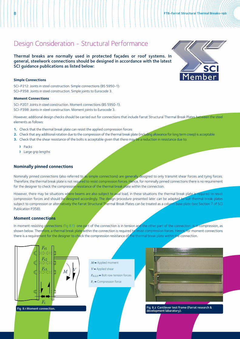
Moment connections
In moment resisting connections (fig 8.1) one part of the connection is in tension and the other part of the connection is in compression, as shown below. Therefore, a thermal break plate within the connection is required to resist compression forces. Hence, for moment connections there is a requirement for the designer to check the compression resistance of the thermal break plate within the connection.
Fig 8.1 Moment connection.
M = Applied moment
V = Applied shear
Fr1,2,3 = Bolt row tension forces
Fc = Compression force
Fig 8.2 Cantilever test frame (Farrat research & development labaratory).
Fr1
Fr2
Fr3
Fc
M V

www.farrat.com 9
1. Applied compressive stress to thermal break
The designer must check that the compressive stress applied to the thermal break plate is less than the design compression strength of the thermal break material. This is achieved by satisfying the expression given below.
The compression force Fc can be obtained from published data for standard moment connections (see SCI-P207 and SCI-P398). Alternatively, Fc can be calculated as part of the normal connection design process if standard moment connections are not used.
The dimensions B and L are calculated based on a dispersal of the compression force from the beam flange as shown in Fig 9.1 and Fig 9.2. However, it should be noted that B and L must be reduced if the beam end plate projection is insufficient for full dispersal of the force or if the column flange width is insufficient for full dispersal of the force.
B and L are defined in the following expressions:
B = tf,b + 2(s + tp)
Where:
tf,b is the beam flange thickness
s is the weld leg length
tp is the end plate thickness
L = bb + 2 x tp
Where:
bb is the beam flange width
tp is the end plate thickness
Fc ≤ B x L x fcd
Fc is the applied compression force (ULS)
fcd is the design value for compressive strength (thermal break)
B is the depth of the compression zone on the thermal break
L is the width of the compression zone on the thermal break
Fig 9.1 Dispersion of force through connection compression zone - dimension B.
Fig 9.2 Dispersion of force through connection compression zone - dimension L.
Farrat Structural Thermal Break plate Beam end plate
Beam flange
Column flange
Column flange
Beam end plate
Thermal break plate compression zoneBeam flange
B
B Fc
L
FTB-Farrat Structural Thermal Breaks-19b10
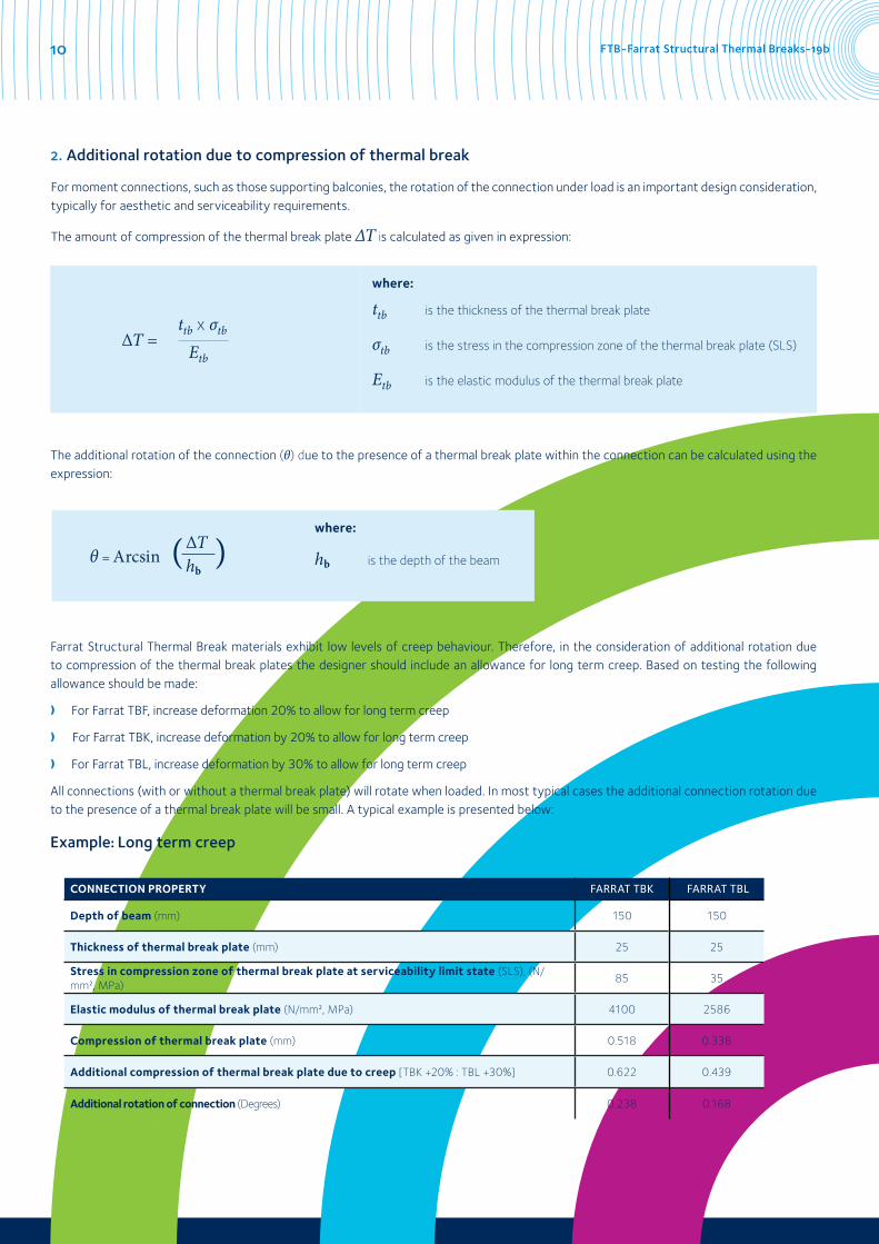
The additional rotation of the connection (θ) due to the presence of a thermal break plate within the connection can be calculated using the expression:
Farrat Structural Thermal Break materials exhibit low levels of creep behaviour. Therefore, in the consideration of additional rotation due to compression of the thermal break plates the designer should include an allowance for long term creep. Based on testing the following allowance should be made:
❫ For Farrat TBF, increase deformation 20% to allow for long term creep
❫For Farrat TBK, increase deformation by 20% to allow for long term creep
❫ For Farrat TBL, increase deformation by 30% to allow for long term creep
All connections (with or without a thermal break plate) will rotate when loaded. In most typical cases the additional connection rotation due to the presence of a thermal break plate will be small. A typical example is presented below:
where:
ttb is the thickness of the thermal break plate
σtb is the stress in the compression zone of the thermal break plate (SLS)
Etb is the elastic modulus of the thermal break plate
θ = Arcsin
where:
hb is the depth of the beam
CONNECTION PROPERTY FARRAT TBK FARRAT TBL
Depth of beam (mm) 150 150
Thickness of thermal break plate (mm) 25 25
Stress in compression zone of thermal break plate at serviceability limit state (SLS), (N/mm², MPa)
85 35
Elastic modulus of thermal break plate (N/mm², MPa) 4100 2586
Compression of thermal break plate (mm) 0.518 0.338
Additional compression of thermal break plate due to creep [TBK +20% : TBL +30%] 0.622 0.439
Additional rotation of connection (Degrees) 0.238 0.168
2. Additional rotation due to compression of thermal break
For moment connections, such as those supporting balconies, the rotation of the connection under load is an important design consideration, typically for aesthetic and serviceability requirements.
The amount of compression of the thermal break plate ∆T is calculated as given in expression:
∆T =ttb x σtb
Etb
Example: Long term creep
∆Thb
( )

www.farrat.com 11
3. Bolt shear resistance
A thermal break plate in a connection must be considered as a pack in terms of the connection design. Where packs are used in connections there are detailing rules that should be followed and depending on the thickness of packs it may be necessary to reduce the shear resistance of the bolts within the connection.
❫ The number of packs should be kept to a minimum (less than 4)
❫ The total thickness of packs tpa should not exceed 4d/3, where d is the nominal diameter of the bolt
❫ If tpa exceeds d/3 then, the shear resistance of the bolts should be reduced by the factor βp given in the expression
βp =
Where:
d is nominal bolt diameter
tpa is the total thickness of packs
9d8d + 3tpa
βg =
where:
d is nominal bolt diameter
Tg is the total grip length of the bolt
4. Large grip lengths
A thermal break plate in a connection will increase the total grip length (Tg) of the bolts. The total grip length is the combined thickness of all the elements that the bolt is connecting together (e.g. end plate, thermal break plate, column flange, additional packs etc). Depending on the size of the grip length it may be necessary to reduce the shear resistance of the bolts within the connection.
If Tg exceeds 5d then, the shear resistance of bolts with large grip lengths should be reduced by the factor βg given in expression.
5. Frictional resistance
a) Non-preloaded bolts
The coefficient of friction of the thermal break plate is not a relevant property for the structural design of connections with non-preloaded bolts.
b) Pre-loaded bolts
For the structural design of connections with preloaded bolts the coefficient of friction of the thermal break plate will be required. The slip resistance of the bolted connection is calculated in accordance with Section 3.9 of BS EN 1993-1-8. The number of friction surfaces is required for this calculation.
In addition, the local compression force around the bolt holes on the thermal break plate must be checked to ensure the compressive strength of the thermal break plate is not exceeded.
Preloaded bolts are also known as HSFG bolts. Please contact Farrat for information relating to frictional resistance of Farrat TBF, Farrat TBK and Farrat TBL.
6. Fire
Generally, thermal breaks are used in locations that do not require fire protection. Where the connection requires a fire rating then the following options are available:
❫ A board fire protection system can be applied.
❫ Sprayed fire protection can be applied. The compatibility of the applied fire protection material should be checked with the thermal break material.
❫ The connection may be designed on the assumption of complete loss of the thermal break material in the accidental condition. ❫ Introduction of 'fail safes', (e.g. steel blocks at bolt positions set below depth of the Structural Thermal Break).
8d3d + Tg
Note: Although all care has been taken to ensure that all the information contained herein is accurate, Farrat Isolevel Limited assumes no responsibility for any errors or misinterpretations or any loss or damage arising therefrom.

Other areas of expertise
Vibration Control, Acoustic & Shock
We have developed a comprehensive range of solutions to the problems of controlling and isolating noise, vibration, shock and movement in both new and existing buildings. Our diverse range of products includes; Floating Floor systems, Isolated Foundations, Structural Bearings, Anti Vibration Washers, Resilient Seatings and Coil Spring and Damper Systems for a variety of different building types.
Support & Levelling of Industrial Machinery
Having manufactured high quality Anti Vibration and Precision Levelling Mountings for more than 50 years, Farrat has developed a rich expertise in this field. These products include a complete range of anti vibration materials, anti vibration washers and anti vibration and levelling mounts. Our products are used in a wide variety of applications, from power presses to roll grinders and printing presses.
Farrat Isolevel Ltd Balmoral Road, Altrincham, Cheshire, WA15 8HJ, England, UKT. +44 (0) 161 924 1600 F. +44 (0) 161 924 1616 E. [email protected] www.farrat.com
Company Registration Number (England): 635283 VAT Registration Number: GB 145 9515 50
Company Directors: O. Farrell, A. Farrell, R.J. Farrell, H.J. Farrell, G.H. Farrell
Next Steps:For further information, technical advice or to place an order, please contact us:
+44 (0) 161 924 1600 [email protected]