structural-timber-design1-pdf.pdf
DESCRIPTION
Structural TimberTRANSCRIPT

im
Sc, MSc, PhD, FIVVSc ~ a ~ i e r ~niver~ity, Edinbur~~
Blackwell Science

0 1999 by Blackwell Science Ltd Editorial Offices: Osney Mead, Oxford OX2 OEL 25 John Street, London WClN 2BL 23 Ainslie Place, Edinburgh EH3 6AJ 350 Main Street, Malden
MA 02148 5018, USA 54 University Street, Carlton
Victoria 3053, Australia 10, rue Casimir Delavigne
75006 Paris, France
Other Editorial Offices:
Blackwell Wissenschafts-Verlag GmbH Kurfurstendamm 57 10707 Berlin, Germany
Blackwell Science KK MG Kodenmacho Building 7-10 Kodenmacho Nihombashi Chuo-ku, Tokyo 104, Japan
The right of the Author to be identified as the Author of this Work has been asserted in accordance with the Copyright, Designs and Patents Act 1988.
All rights reserved. No part of this publication may be reproduced, stored in a retrieval system, or transmitted, in any form or by any means, electronic, mechanical, photocopying, recording or otherwise, except as permitted by the UK Copyright, Designs and Patents Act 1988, without prior permission of the publisher.
First published 1999
Set in 10/12.5 pt Times by Aarontype Limited, Easton, Bristol Printed and bound in Great Britain by The University Press, Cambridge
The Blackwell Science logo is a trade mark of Blackwell Science Ltd, registered at the United Kingdom Trade Marks Registry
DISTRIBUTORS Marston Book Services Ltd PO Box 269 Abingdon Oxon OX14 4YN (Orders: Tel: 01235 465500
Fax: 01235 465555)
USA Blackwell Science, Inc. Comerce Place 350 Main Street Malden, MA 02148 5018 (Orders: Tel: 800 759 6102
'781 388 8250 Fax: 781 388 8255)
Canada Login Brothers Book Company 324 Saulteaux Cresent Winnipeg, Manitoba R3J 3T2 (Orders: Tel: 204 837 2987
Fax: 204 837 3 116)
Australia Blackwell Science Pty Ltd 54 University Street Carlton, Victoria 3053 (Orders: Tel: 03 9347 0300
Fax: 03 9347 5001)
A catalogue record for this title is available from the British Library ISBN 0-632-0509 1-8
For further information on Blackwell Science, visit our website: www.blackwel1-science.com
Although every care has been taken to ensure, to the best of our knowledge, that all data and information contained herein are accurate at the time of publication, the author or the publishers can assume no liability for any errors in or misinterpretations of such data and/or information or any loss or damage arising from or related to their use.

To Roman

This Page Intentionally Left Blank
Preface xi
1 Timber as a Structural Material 1.1 ~ntroduction 1.2 The structure of timber 1.3 Defects in timber
1.3.1 Natural defects 1.3.2 Chemical defects 1.3.3 Conversion defects 1.3.4 Seasoning defects
l .4.1 Softwoods 1.4.2 Hardwoods
1.5 Physical properties of timber 1 .5. 1 Moisture content 1.5.2 Density 1 5.3 Slope of grain 1.5.4 Timber defects
1.4 Types of timber
1.6 References
S 5268 : Part 2 : 11996 2.1 Introduction 2.2 Design philosophy 2.3 Stress grading of timber
2.3.1 Visual grading 2.3.2 Machine grading
2.4 Strength classes 2.5 Design considerations (factors affecting timber strength)
2.5.1 Loading 2.5.2 Service classes 2.5.3 Moisture content 2.5.4 Duration of loading
1 1 3 3 4 5 5 5 5 5 6 6 7 7 8 8
9 9
10 12 12 12 13 14 14 14 16 16
V
vi Contents
2.5.5 Section size 2.5.6 Load-sharing systems 2.5.7 Additional properties
2.6 Symbols 2.7 References
3 Using Mathcad@ for Design C ~ c u l a ~ o n s 3.1 Introduction 3.2 What is Mathcad? 3.3 What does Mathcad do?
3.3.1 A simple calculation 3.3.2 Definitions and variables 3.3.3 Entering text 3.3.4 Working with units
3.4 Summary 3.5 References
4 Design of Flexural Members (Beams) 4. l 4.2 4.3
4.4
4.5
4.6
4.7 4.8 4.9
Introduction Design considerations Bending stress and prevention of lateral buckling 4.3.1 EAFective span, L, 4.3.2 Form factor, KG 4.3.3 Depth factor, K7 4.3.4 Selection of a suitable section size 4.3.5 Lateral stability 4.3.6 An illustrative example Deflection 4.4.1 Deflection limits 4.4.2 Precamber 4.4.3 Bending deflection 4.4.4 Shear deflection Bearing stress 4.5.1 Length and position of bearings Shear stress 4.6.1 Shear at notched ends Suspended timber flooring References Design examples Example 4.1 Example 4.2 Example 4.3 Example 4.4
17 18 18 19 20
21. 21 21 22 22 22 24 24 25 25
26 26 26 27 28 29 29 30 30 31 32 32 33 33 34 34 35 36 36 37 39 40 40 43 46 50

Contents vii
esign of Axially Loaded Members 5. l Introduction 5.2 Design of compression members
5.2. l 5.2.2 5.2.3 5.2.4
5.2.5
5.2.6
Design considerations Slenderness ratio, h Modification factor for compression members, K12 Members subjected to axial compression only (Clause 2.1 1.5) Members subjected to axial compression and bending (Clause 2.1 l .6) Design of load-bearing stud walls
5.3 Design of tension members (Clause 2.12) 5.3.1 Design considerations 5.3.2 Width factor, K14 5.3.3 Members subjected to axial tension only 5.3.4 Combined bending and tensile stresses
5.4 Design examples Example 5.1 Example 5.2 Example 5.3 Example 5.4 Example 5.5
6 Design of Glued Laminated Members 6.1 6.2 6.3
6.4
6.5 6.6 6.7 6.8
Introduction Design considerations Grade stresses for horizontally glued laminated members 6.3.1 Single-grade members 6.3.2 Combined-grade members 6.3.3 Permissible stresses for horizontally glued laminated
Grade stresses for vertically glued laminated beams 6.4.1 Permissible stresses for vertically glued laminated
Deformation criteria for glued laminated beams Curved glued laminated beams Bibliography Design examples Example 6.1 Example 6.2 Example 6.3 Example 6.4 Example 6.5
members
members
56 56 56 56 57 58
60
61 62 63 64 64 64 65 66 66 69 73 75 79
82 82 84 84 84 84
86 87
89 90 90 92 93 93 97
102 113 119

viii Contents
7.1 7.2 7.3 7 '4
7.5 7.6
esign of P l y - w e b b ~ Beams Introduction Transformed (effective) geometrical properties Plywood Design considerations 7.4. l Bending 7.4.2 Deflection 7.4.3 Panel shear 7.4.4 Rolling shear 7.4.5 Lateral stability 7.4.6 Web-stiffeners References Design examples Example 7.1 Example 7.2
123 123 l 24 125 127 128 129 130 130 131 131 132 132 132 137
8 Design of Built-up (Spaced) Columns 143 8.1 8.2 8.3
8.4 8.5 8.6
Introduction Spaced columns Design considerations 8.3.1 Geometrical requirements 8.3.2 Modes of failure and permissible loads 8.3.3 Shear capacity of spacer blocks Compression members in triangulated frameworks Reference Design examples Example 8.1 Example 8.2
esign of Timber Connections 9. l Introduction 9.2 General design considerations 9.3 Joint slip 9.4 Effective cross-section 9.5 Spacing rules 9.6 Multiple shear lateral loads 9.7 Nailed joints
9.7.1 Improved nails 9.7.2 Pre-drilling 9.7.3 Basic single shear lateral loads 9.7.4 Axially loaded nails (withdrawal loads) 9.7.5 Permissible load for a nailed joint
9.8.1 Basic single shear lateral loads 9.8.2 Axially loaded screws (withdrawal loads) 9.8.3 Permissible load for a screwed joint
9.8 Screwed joints
143 144 145 145 145 147 148 148 148 148 152
159 159 160 161 162 163 165 166 167 167 169 172 173 175 176 177 178

Contents ix
9.9
9.10 9.1 1
9.12
9.13 9.14
Bolted and dowelled joints 9.9.1 Basic single shear lateral loads 9.9.2 Permissible load for a bolted or dowelled joint Moment capacity of dowel-type fastener joints Connectored joints 9.1 l. l Toothed-plate connectors 9.1 l .2 Split-ring and shear-plate connectors 9.1 l .3 Metal-plate connectors Clued joints 9.12.1 Durability classification 9.12.2 Design considerations for glued joints References Design examples Example 9.1 Example 9.2 Example 9.3 Example 9.4 Example 9.5 Example 9.6 Example 9.7 Example 9.8
esign to Euroco~e 5 10.1 10.2 10.3 10.4
10.5
10.6
10.7 10.8
Introduction Design philosophy Actions Material properties 10.4.1 Design values Ultimate limit states 10.5.1 10.5.2 10.5.3 10.5.4 10.5.5
10.5.6
10.5.7
Bending Shear Compression perpendicular to grain (bearing) Compression or tension parallel to grain Members subjected to combined bending and axial tension Columns subjected to combined bending and axial compression Dowel-type fastener joints
Serviceability limit states 10.6.1 Deflections 10.6.2 Vibrations 10.6.3 Joint slip Reference Bibliography
179 180 184 185 188 189 191 193 195 195 196 196 197 197 199 20 1 204 208 210 213 216
219 220 22 1 22 1 223 224 225 227 228 229
230
230 23 1 239 239 240 24 1 242 242

x Contents
10.9 Design examples Example 10.1 Example 10.2 Example 10.3
242 242 248 25 1
Appendix A: Section Sizes for Softwood Timber 257 Appendix B: Weights of Building ater rials 259 Appendix C: Related British Standards for Timber Engineering 260
Index 263

The increasing recognition of timber as a structural material is reflected in the inclusion of timber design in many undergraduate courses. majority of design textbooks for undergraduate engineering students neg- lect, to a large extent, the importance of timber as a structural and building material. As a consequence, relatively few textbooks provide information on the design of timber structures. Structural Timber Design is intended to address this issue by providing a step-by-step approach to the design of all the most commonly used timber elements and joints illustrated by detailed worked examples. This is an approach which is recognised to be beneficial in learning and preferred by most students.
The book has been written for undergraduate students on building, civil and structural engineering and architectural courses and will be an invaluable reference source and design aid for practising engineers and postgraduate engineering students. It provides a comprehensive source of information on practical timber design and encourages the use of computers to carry out design calculations.
Chapter 1 introduces the nature and inherent characteristics of timber such as defects, moisture content and slope of grain, and discusses the types of timber and factors that influence their structural characte includes a comprehensive review of the recently revised
t 2: 1996: Structural Use of Timber. The design philosophy of its new approach to the strength class system and also the
factors affecting timber strength are explained. Chapter 3 gives an overview of Mathcad@, a computer software pro-
gramme used to carry out mathematical calculations, and details its simplicity and the advantages that it provides when used for design calcu- lations. The aim is to encourage readers to use computing as a tool to increase their under-standing of how design solutions vary in response to a change in one of the variables and how alternative design options can be obtained easily and effortlessly. The design of basic elements is explained and illustrated in Chapters 4 and 5, whilst the design of more specialised elements such as glued laminated straight and curved beams and columns, ply-webbed beams and built-up columns is illustrated in Chapters 6, 7 and 8 using numerous worked examples.
xi

xii Preface
In Chapter 9 the design of timber connections is detailed. The new approach adopted by the revised BS 5268 : Part 2 in 1996, i.e. the Eurocode 5 approach for the design of timber joints, is described. The chapter includes a comprehensive coverage of the design requirements for nailed, screwed, bolted and dowelled joints, and the design of connectored joints such as toothed-plates, split-rings and shear-plates and glued connections is also detailed. Several step-by-step worked examples are provided to illustrate the design methods in this chapter.
Chapter 10 provides a comprehensive review of the proposed European code for timber, Eurocode 5: Design of Timber Structures. The limit states design philosophy of EC5 is explained and the relevant differences with the design methodology of BS 5268 are high~ghted and discussed. This chapter also provides comprehensive coverage of EC5 requirements for the design of flexural and axially 1o.aded members and dowel-type connections such as nailed, screwed, bolted and dowelled joints. Again, step-by-step worked examples are provided to illustrate the design methods in the chapter.
All design examples given in this book are produced in the form of worksheet files and are available from the author on 3 r disks to run under Mathcad computer software Version 6, or higher, in either one of its editions: (Student, Standard, Plus or Professional). Details are given at the end of the book. The examples are fully self-explanatory and well annotated and the author is confident that the readers whether students, course instructors, or practising design engineers will find them extremely useful to produce design solutions or prepare course handouts. In particular, the worksheets will allow design engineers to arrive at the most suitable/ economic solution(s) very quickly.
Extracts from British Standards are reproduced with the permission of BSI under licence no. PD\1998 0823. Complete editions of the standards can be obtained by post from BSI Customer Services, 389 Chiswick High Road, London'W4 4AL.
The cover illustration was kindly supplied by MiTek Industries Ltd.

ructural
1 .1 Introduction
Timber has always been one of the more plentiful natural resources available and consequently is one of the oldest known materials used in construction. It is a material that is used for a variety of structural forms such as beams, columns, trusses, girders and is also used in building systems such as piles, deck members, railway foundations and for temporary foms in concrete.
Timber structures can be highly durable when properly treated and built. Examples of this are seen in many historic buildings all around the world. Timber possesses excellent insulating properties, good fire resistance, light weight and aesthetic appeal. A great deal of research carried out since the early part of this century has provided us with comprehensive information on structural properties of timber and timber products'. A knowledge of engineering materials is essential for engineering design.
Timber is a traditional building material and over the years considerable knowledge has been gained on its important material properties and their effects on structural design and service behaviour. Many failures in timber buildings in the past have shown us the safe methods of construction, connection details and design limitations.
This chapter provides a brief description of the engineering properties of timber that are of interest to design engineers or architects. But it should be kept in mind that, unlike some structural materials such as steel or concrete, the properties of timber are very sensitive to environmental conditions. For example, timber is very sensitive to moisture content, which has a direct effect on the strength and stiffness, swelling or shrinkage of timber. A proper understanding of the physical characteristics of wood aids the building of safe timber structures"
1.2 The structure of timber *
Mature trees of whatever type are the source of structural timber and it is important that users of timber should have a knowledge of the nature and growth patterns of trees in order to understand its behaviour under a variety
1
Structural Timber Design
of circumstances. Basically, a tree has three subsystems: roots, trunk and ow^^ Each subsystem has a role to play in the growth pattern of the tree.
Roots, by spreading through the soil as well as acting as a foundation, enable the growing tree to withstand wind forces. They absorb moisture containing minerals from the soil and transfer it via the trunk to the crown. Trunk provides rigidity, mechanical strength and height to maintain the crown, Also transports moisture and minerals up to the crown and sap down from the crown. Crown provides as large as possible a catchment area covered by leaves. These produce chemical reactions that form sugar and cellulose which cause the growth of the tree.
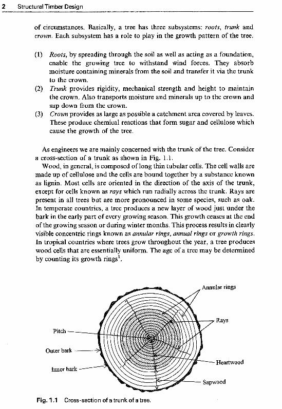
A s engineers we are mainly concerned with the trunk of the tree. Consider a cross-section of a trunk as shown in Fig. 1.1.
Wood, in general, is composed of long thin tubular cells. The cell walls are made up of cellulose and the cells are bound together by a substance known as lignin. Most cells are oriented in the direction of the axis of the trunk, except for cells known as rays which run radially across the trunk. Rays are present in all trees but are more pronounced in some species, such as oak. In temperate countries, a tree produces a new layer of wood just under the bark in the early part of every growing season. This growth ceases at the end of the growing season or during winter months. This process results in clearly visible concentric rings known as annular rings, annual rings or growth rings. In tropical countries where trees grow throughout the year, a tree produces wood cells that are essentially uniform. The age of a tree may be determined by counting its growth rings'.
Fig. 1 .l Cross-section of a trunk of a tree.
Timber as a Structural Material 3
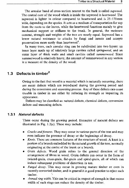
The annular band of cross-section nearest to the bark is called sapwood. The central core of the wood which is inside the sapwood is heartwood. The sapwood is lighter in colour compared to heartwood and is 25-170mm wide, depending on the species. It acts as a medium of transportation for sap from the roots to the leaves, while the heartwood functions mainly to give mechanical support or stiffness to the trunk. In general, the moisture content, strength and weights of the two are nearly equal. Sapwood has a lower natural resistance to attacks by fungi and insects and accepts preservatives more easily than heartwood',
In many trees, each annular ring can be subdivided into two layers: an inner layer made up of relatively large cavities called springwood, and an outer layer of thick walls and small cavities called summerwood, Since summerwood is relatively heavy, the amount of summerwood in any section is a measure of the density of the wood.
efects in timber2
Owing to the fact that wood is a material which is naturally occurring, there are many defects which are introduced during the growing period and during the conversion and seasoning process. Any of these defects can cause trouble in timber in use either by reducing its strength or impairing its appearance.
Defects may be classified as: natural defects, chemical defects, conversion defects and seasoning defects.
t~ raJ defects
These occur during the growing period. Examples of natural defects are illustrated in Fig. 1.2(a). These may include:
Cracks and3ssures. They may occur in various parts of the tree and may even indicate the presence of decay or the beginnings of decay. Knots. These are common features of the structure of wood. A knot is a portion of a branch embedded by the natural growth of the tree, normally originating at the centre of the trunk or a branch.
e Grain defects. Wood grain refers to the general direction of the arrangement of fibres in wood. Grain defects can occur in the form of twisted-grain, cross-grain, flat-grain and spiral-grain, all of which can induce subsequent problems of distortion in use.
e Fungal decay. This may occur in growing mature timber or even in recently converted timber, and in general it is good practice to reject such timber. \
e Annual ring width. This can be critical in respect of strength in that excess width of such rings can reduce the density of the timber.

Structural Timber Design
Shake Icnot Wane
Diagonal-grain Cross-grain
(a) Natural and conversion defects
Flat-grain
Cupping End splitting ~ o n e y c o ~ b i n g
Springing
Defects in timber.
Bowing Twisting
(b) Seasoning defects
These may occur in particular instances when timber is used in unsuitable positions or in association with other materials. Timbers such as oak and western red cedar contain tannic acid and other chemicals which corrode

Timber as a Structural Material 5
metals. Gums and resins can inhibit the working properties of timber and interfere with the ability to take adhesives.
1. o ~ ~ e r s i o ~ defects
These are due basically to unsound practice in the use of milling techniques or to undue economy in attempting to use every possible piece of timber converted from the trunk. A wane is a good example of a conversion defect.
Seasoning defects are directly related to the movement that occurs in timber due to changes in moisture content. Excessive or uneven drying, exposure to wind and rain, and poor stacking and spacing during seasoning can all produce defects or distortions in timber. Examples of seasoning defects are illustrated in Fig. 12(b). All such defects have an effect on structural strength as well as on fixing, stability, durability and finished appearance.
Trees and commercial timbers are divided into two groups: softwoods and hardwoods. This terminology has no direct bearing on the actual softness or hardness of the wood.
Softwoods are generally evergreen with needle-like leaves comprising single cells called tracheids, which are like straws in plan, and they fulfil the functions of conduction and support. Rays, present in softwoods, run in a radial direction perpendicular to the growth rings. Their function is to store food and allow the convection of liquids to where they are needed.
oft woo^ characteristics
0 Quick growth rate; trees can be felled after 30 years, resulting in low density timber with relatively low strength. Generally poor durability qualities, unless treated with preservatives. Due to speed of felling, they are readily available and comparatively cheap.
1.4.2 ~ ~ r d w o o d s
Hardwoods are generally broad-leaved (deciduous) trees that lose their leaves at the end of each growing season. The cell structure of hardwoods is
6 Structural Timber Design
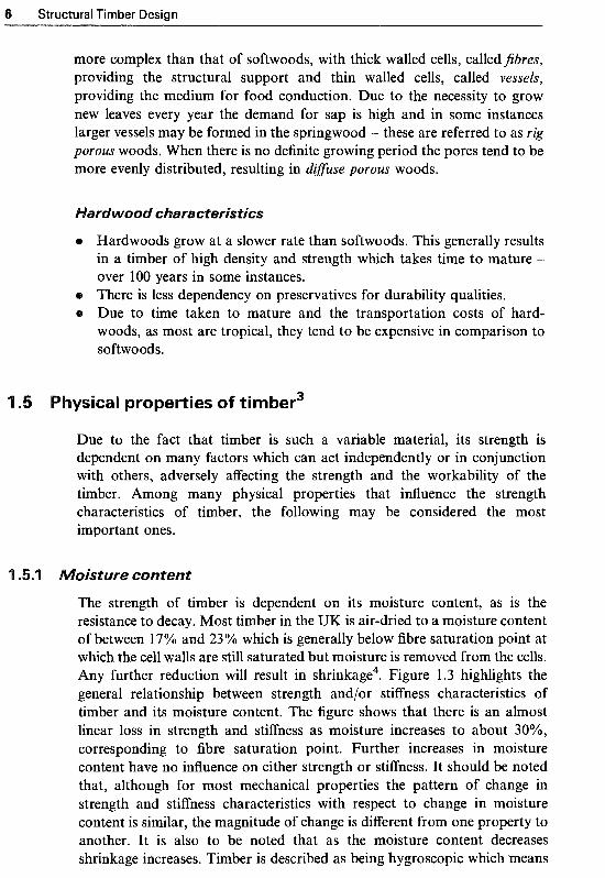
more complex than that of softwoods, with thick walled cells, called Jibres, providing the structural support and thin walled cells, called vessels, providing the medium for food conduction. Due to the necessity to grow new leaves every year the demand for sap is high and in some instances larger vessels may be formed in the springwood - these are referred to as rig porous woods. When there is no definite growing period the pores tend to be more evenly distributed, resulting in dzfuse porous woods.
rdwood characteristics
Hardwoods grow at a slower rate than softwoods. This generally results in a timber of high density and strength which takes time to mature - over 100 years in some instances. There is less dependency on preservatives for durability qualities. Due to time taken to mature and the transportation costs of hard- woods, as most are tropical, they tend to be expensive in comparison to softwoods.
ysical properties of timber3
Due to the fact that timber is such a variable material, its strength is dependent on many factors which can act independently or in conjunction with others, adversely affecting the strength and the workability of the timber. Among many physical properties that influence the strength characteristics of timber, the following may be considered the most important ones.
'l .5.1 isture content
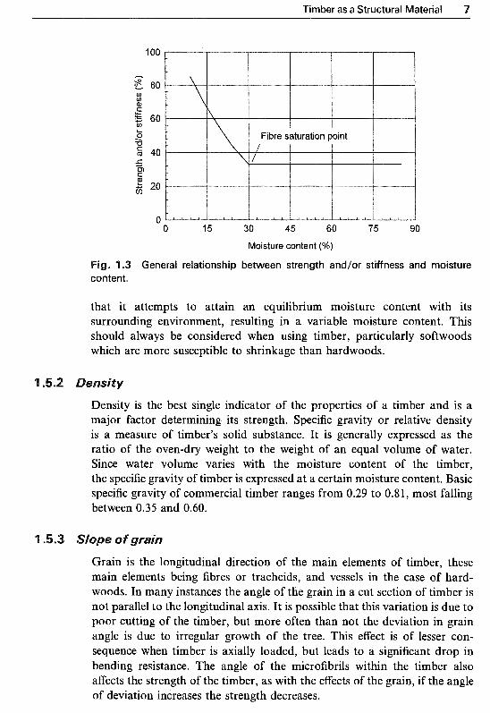
The strength of timber is dependent on its moisture content, as is the resistance to decay. Most timber in the UK is air-dried to a moisture content of between 17% and 23% which is generally below fibre saturation point at which the cell walls are still saturated but moisture is removed from the cells. Any further reduction will result in shrinkage4. Figure 1.3 highlights the general relationship between strength andlor stiffness characteristics of timber and its moisture content. The figure shows that there is an almost linear loss in strength and stifkess as moisture increases to about 30%, corresponding to fibre saturation point. Further increases in moisture content have no influence on either strength or stiffness. It should be noted that, although for most mechanical properties the pattern of change in strength and stiffness characteristics with respect to change in moisture content is similar, the magnitude of change is different from one property to another. It is also to be noted that as the moisture content decreases shrinkage increases. Timber is described as being hygroscopic which means
Timber as a Structural Material 7
100
E 80 h
U) U)
S
60 U)
ti % -0
40 5 P ; 20
0
Fibre saturation point I
0 15 30 45 60 75 90
Moisture content (%)
Fig. 1.3 General relationship between strength and/or stiffness and moisture content.
that it attempts to attain an equilibrium moisture content with its surrounding environment, resulting in a variable moisture content. This should always be considered when using timber, particularly softwoods which are more susceptible to shrinkage than hardwoods.
Density is the best single indicator of the properties of a timber and is a major factor determining its strength. Specific gravity or relative density is a measure of timber's solid substance. It is generally expressed as the ratio of the oven-dry weight to the weight of an equal volume of water. Since water volume ' varies with the moisture content of the timber, the specific gravity of timber is expressed at a certain moisture content. specific gravity of commercial timber ranges from 0.29 to 0.8 1, most falling between 0.35 and 0.60.
Grain is the longitudinal direction of the main elements of timber, these main elements being fibres or tracheids, and vessels in the case of hard- woods. In many instances the angle of the grain in a cut section of timber is not parallel to the longitudinal axis. It is possible that this variation is due to poor cutting of the timber, but more often than not the deviation in grain angle is due to irregular growth of the tree. This effect is of lesser con- sequence when timber is axially loaded, but leads to a significant drop in bending resistance. The angle of the microfibrils within the timber also affects the strength of the timber, as with the effects of the grain, if the angle of deviation increases the strength decreases.

8 Structural Timber Design
1 -5.4 Timber defects
As described earlier, defects in timber, whether natural or caused during conversion or seasoning, will have an eEect on structural strength as well as on fixing, stability, durability and finished appearance of timber.
1.6 References
Somayaji, S. (1990) Structural Wood Design. West Publishing Company, St. Paul, U.S.A. Illston, J.M., Dinwoodie, J.M. and Smith, A.A. (1979) Concrete, Timber and Metals - The Nature and Behaviour of Structural Materials. Van Nostrand Reinhold International, London. Illston, J.M. (1994) Construction ater rials - Their Nature and Behaviour. E. & F.N. Spon, London. Carmichael, E.N. (1984) Timber Engineering. E. & F.N. Spon, London.

hapter r
Strength capability of timber is difficult to assess as we have no control over its quality and growth. The strength of timber is a function of several param- eters including the moisture content, density, duration of the applied load, size of members and presence of various strength-reducing characteristics such as slope of grain, knots, fissures and wane. To overcome this difficulty, the stress grading method of strength classification has been devised'.
Guidance on the use of timber in building and civil engineering structures is given in BS 5268: Structural use of timber. This was originally divided into seven parts:
Part 1: Limit state design, materials and workmanship. Part 2: Code of practice for permissible stress design, materials and
Part 3: Code of practice for trussed rafter roofs. Part 4: Fire resistance of timber structures. Part 5: Preservation treatments for constructional timber. Part 6: Code of practice for timber framed walls. Part 7: Recommendations for the calculation basis for span tables.
workmanship.
Part l of BS 5268 was never completed and, with the introduction of Eurocode 5: DD ENV 1995-1-1: Design of timber structures, the develop- ment of this part was completely abandoned.
Part 2 of BS 5268, on which the design of structural timber is based, was originally published as CP 112 in 1952 and revised later in 1967 and, with extensive amendment, in 1971. The 'basic stresses' introduced in CP 1 12 were determined from carrying out short-term loading tests on small timber specimens free from all defects. The data was used to estimate the minimum strength which was taken as the value below which not more than 1 % of the test results fell. These strengths were multiplied by a reduction factor to give basic stresses. The reduction factor made an allowance for the
9
'l 0 Structural Timber Design
reduction in strength due to duration for loading, size of specimen and other effects normally associated with a safety factor, such as accidental overload- ing, simplifying assumptions made during design and design inaccuracy, together with poor workmanship. Basic stress was defined as the stress that could be permanently sustained by timber free from any strength-reducing characteristics'.
Since 1967 there have been continuing and significant changes affecting the structural use of timber. Research studies in the UK and other countries had shown the need for a review of the stress values and modification factors given in the original code.
With the introduction of BS 5268 in 1984 the concept of 'basic stresses' was largely abandoned and the new approach for assessing the strength of timber moved somewhat in line with 'limit states' design philosophy. In 1996, Part 2 of BS 5268 was revised with a clear aim to bring this code as close as possible to, and to run in parallel with, Eurocode 5: DD ENV 1995-1 -1: Design of timber structures, Part 1.1 General rules and rules for buildings. The overall aim has been to incorporate material specifications and design approaches from Eurocode 5, while maintaining a permissible stress code with which designers, accustomed to BS 5268, will feel familiar and be able to use with- out difficulty. The first step in this process involves strength grading of timber sections. There are two European standards which relate to strength grading:
BS EN 5 18 : 1995 Structural timber. Grading. Requirements for visual strength grading standards. BS EN 519 ; 1995 Structurul t i ~ b e r . Grading. Requiremen~s for ~ a c h i n ~ strength graded timber and grading machines.
dance for stress grading of the two typ timber, namely softwoods hardwoods, are given in the following
S 4978 : 1996 Spec~cation for softwoods graded for structural use. S 5756 : 1997 Spec~cation for tropical hard woo^ graded for str~ctural use.
The current revised versions of these standards conform with the
The structural design of timber members is related to Part 2 of BS 5268, and is based on permissible stress design philosophy in which design stresses are derived on a statistical basis and deformations are also limited.
Elastic theory is used to analyse structures under various loading con- ditions to give the worst design case. Then timber sections are chosen so that the permissible stresses are not exceeded at any point of the structure.

Introduction to BS 5268: Part 2: 1996 11
Permissible stresses are calculated by multiplying the ‘grade stresses’, given in Tables 7 to 12a of BS 5268 : Part 2, by the appropriate modification factors, K-factors, to allow for the effects of parameters such as load duration, moisture content, load sharing, section size, etc. Applied stresses which are derived from the service loads should be less than or equal to the permissible stresses. A summary of the K-factors used for the calculation of permissible stresses is given in Table 2.1. Owing to changes made to BS 5268 : Part 2 in 1996, some K-factors which were used in the previous editions, such as IC1, K10, etc., have been withdrawn.
The permissible stress design philosophy, as in BS 5268 : Part 2, is different from the limit states design philosophy of Eurocode 5 which has two basic requirements. The first is ultimate limit states (i.e. safety) which is usually
Table 2.1 Summary of K-factors used for calculation of permissible stresses
K-factor Description or application BS 5268 : Part 2 : 1996
K2
K3 K4
K5
K7
K8
K9
K 12
K6
K1 3
K1 4
K1 5-20
K27-29
K30-32
K33-34 K35
K36
K37
K,,, K3841
K43-50
K52-54
K56, 57
KS,C,58-61
KS,C,D,62-65
Timber grade stresses and moduli for service class 3 Duration of loading Bearing stress Shear at notched ends Form factor: bending stress for non-rectangular sections Depth factor: bending stress for beams other than
Load sharing systems To modify Emin for deflection in trimmer beams and lintels Slenderness in compression members Efktive length of spaced columns Width factor for tension members Single grade glued laminated members and horizontally
Vertically glued laminated members Individually designed glued end joints in horizontally
glued laminated members Curved glued laminated beams Stress factor in pitched cambered softwood beams Plywood grade stresses for duration of loading and
Stress concentration factor for ply-webbed beams For tempered hardboards Fastener slip moduli Nailed joints Screwed joints Bolted and dowelled joints Toothed-plate connector joints Split-ring connector joints
300mm deep
laminated beams
service classes
Ks,C,D,66-69 Shear-plate connector joints K70 Glued joints
Table 13 Table 14 Table 15 Clause 2.10.4 Clause 2.10.5 Clause 2.10.6
Clause 2.9 Table 17 Table 191Annex B Table 20 Clause 2.12.2 Table 21
Table 22 Table 23
Clause 3.5.3 Clause 3.5.4.2 Table 33
Clause 4.6 Section 5 Table 52 Clause 6.4 Clause 6.5 Clause 6.6 Clause 6.7 Clause 6.8 Clause 6.9 Clause 6.10

12 Structural Timber Design
expressed in terms of load-carrying capacity and is achieved by factoring-up of load values and factoring-down of material strength properties by partial safety factors that reflect the reliability of the values that they modify. The second is servi~eability limit states (i.e. deformation and vibration limits) which refers to the ability of a structural system and its elements to perform satisfactorily in normal use.
It is important to note that in permissible stress design philosophy partial safety factors (i.e. modification factors) are applied only to material prop- erties, i.e. for the calculation of permissible stresses, and not to the loading.
Once timber has been seasoned it is stress graded; this grading will determine the strength class of the timber to satisfy the design requirements of BS 5268 : Part 2. Strength grading takes into account defects within the timber such as slope of grain, existence and extent of knots and fissures, etc.
All timber used for structural work needs to be strength graded by either visual inspection or by an approved strength grading machine. Clause 2.5 of BS 5268 : Part 2 deals with strength grading of timber.
3 . 1 ual gra~ing
Visual grading is a manual process carried out by an approved grader. The grader examines each piece of timber to check the size and frequency of specific physical characteristics or defects, e.g. knots, slope of grains, rate of growth, wane, resin pockets and distortion, etc.
The required specifications are given in BS 4978 and BS 5756 to determine if a piece of timber is accepted into one of the two visual stress grades or rejected. These are General Structural (GS) and Special Structural (SS) grades. Table 2 of BS 5268 : Part 2 (reproduced here as Table 2.2) refers to main softwood combinations of species visually graded in accordance with BS 4978,
Machine grading of timber sections is carried out on the principle that strength is related to stiffness. The machine exerts pressure and bending is induced at increments along timber length. The resulting deflection is then automatically measured and compared with pre-programmed criteria, which leads to the grading of timber section. BS 5268 : Part 2, Clause 2.5 specifies that machine graded timber, other than that carried out by North American Export Standard for Machine Stress-rated Lumber (e.g. 1450f-1.3E), should meet the requirements of BS EN 519. To this effect timber is graded directly to the strength class boundaries and marked accordingly.

Introduction to BS 5268: Part 2: 1996 13
In general less material is rejected if it is machine graded, however timber is also visually inspected during machine grading to ensure major defects do not exist.
The concept of grouping timber into strength classes was introduced into the UK with BS 5268 : Part 2 in 1984~~trength classes offer a number of advant- ages both to the designer and the supplier of timber. The designer can undertake his design without the need to check on the availability and price of a large number of species and grades which he might use. Suppliers can supply any of the specieslgrade combinations that meet the strength class called for in a specification. The concept also allows new species to be introduced onto the market without affecting existing specifications for timber.
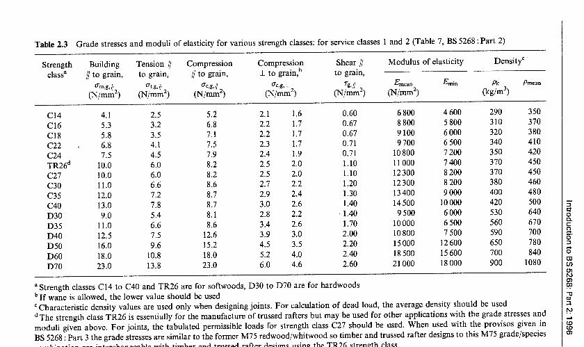
The latest strength classes used in the current version of BS 5268 : Part 2 : 1996 relate to the European strength classes which are defined in BS EN 338 : 1995 Structural timber. Strength classes. There are a total of 16 strength classes, C14 to C40 for softwoods and D30 to D70 for hardwoods as given in Table 7 of BS 5268 : Part 2 : 1996 (reproduced here as Table 2.3). The number in each strength class refers to its ‘characteristic bending strength’ value, for example, C40 timber has a characteristic bending strength of 40N/mm2. It is to be noted that characteristic strength values are con- siderably larger than the grade stress values used in BS 5268 : Part 2, as they do not include effects of long-term loading and safety factors.
oftw wood grading: Softwoods which satisfy the requirements for strength classes given in BSEN 338 when graded in accordance with BS4978 and American timber standards NLGA and NGRDL are given in Tables 2, 3 ,4 and 5 of BS 5268 : Part 2. The new strength classes for softwoods are C14, C16, C18, C22, C24, TR26, C27, C30, C35 and C40. However it is likely that the old strength class system (i.e. SC1 to SC9) may be encountered for some time. A comparison of the lowest of the new strength class (C classes) against the most common old SC classes can be made: SC3 compares with C16, SC4 with C24, and SC5 with C27. TR26 timber, which is commonly used for axially loaded members (i.e. trussed rafters), is equivalent to the superseded M75 European redwood/whitewood.
~ a r d ~ o o d grading: Tropical hardwoods which satisfy the requirements for strength classes given in BS EN 338 when graded to HS grade in accordance with BS 5756 are given in Table 6 of BS 5268 : Part 2 : 1996. The strength classes for tropical hardwoods are D30, D35, D40, D50, D60 and D70.
Grade stresses: Grade stresses and moduli of elasticity for service classes l and 2 (described in Section 2.5.2) are given in Table 7 of BS 5268 : Part 2 for

14 Structural Timber Design
Table 2.2 Softwood combinations of species and visual grades which satisfy the require- ments for various strength classes. Timber graded in accordance with BS4978 (Table 2, BS 5268 : Part 2)
Timber species Strength classes
C14 . C16 C18 C22 C24 C27 C30
Imported: Parana pine Caribbean pitch pine Redwood Whitewood Western red cedar
Douglas fir-larch (Canada and USA) Hem-fir (Canada and USA) Spruce-pine-fir (Canada and USA) Sitka spruce (Canada) Western white woods (USA) Southern pine (USA)
British grown: Douglas fir Larch British pine British spruce
CS ss GS ss GS ss
GS ss
CS ss CS ss GS ss GS ss
CS ss GS ss
GS ss
GS ss CS ss GS ss
GS ss
16 strength classes, and in Tables 8 to 12a for individual softwood and hardwood species and grades. Table 7 is reproduced here as Table 2.3.
erations (factors affecting tim
As mentioned previously, there are several factors which influence timber strength and hence they should be considered in the analysis-design process of all structural timber members, assemblies and frameworks. The main design criteria recommended by BS 5268 : Part 2, Clause l .6 for considera- tion are listed below.
For the purpose of design, loading should be in accordance with BS 6399 : Parts 1, 2, and 32 and CP 3: Chapter V : Part 23 or other relevant standards, where applicable.
2.5.2 Service classes
Due to the effects of moisture content on mechanical properties of timber, the permissible property values should be those corresponding to one of the
introduction to BS 5268: Part 2: 1 996
15

16 Structural Timber Design
Table 2.4 Modification factor K2 for obtaining stresses and moduli applicable to service class 3 (Table 13, BS 5268 : Part 2)
Property K2
Bending parallel to grain 0.8 Tension parallel to grain 0.8 Compression parallel to grain 0.6 Compression perpendicular to grain 0.6 Shear parallel to grain 0.9 Mean and minimum modulus of elasticity 0.8
three service classes described in Clause 1.6.4 and given in Table 1 of BS 5268 : Part 2 : 1996. These are summarised below:
(1) Service class I refers to timber used internally in a continuously heated building. The average moisture content likely to be attained in service condition is 12%.
(2) Service class 2 refers to timber used in a covered building. The average moisture content likely to be attained in service condition if building is generally heated is 15%, and if unheated, 18%.
(3) Service class 3 refers to timber used externally and fully exposed. The average moisture content likely to be attained in service condition is over 20%.
Grade stress and elastic moduli values given in Tables 7 to 12a of BS 5268 : Part 2 apply to various strength classes and timber species in service classes 1 and 2. For service class 3 condition they should be multiplied by the modification factor K2 from Table 13 of the code (reproduced here as Table 2.4).
2.5. j ~ t ~ r e content
A s moisture content affects the structural properties of timber significantly, BS 5268 : Part 2 : 1996 recommends that in order to reduce movement and creep under load the moisture content of timber and wood-based panels when installed should be close to that likely to be attained in service.
Duration of load affects timber strength and therefore the permissible stresses. The grade stresses (Tables 7 to 12a) and the joint strengths given in BS 5268 :Part 2 are applicable to long-term loading. Because timber and wood-based materials can sustain a much greater load for a short period

Introduction to BS 5268: Part 2: 1996 17
Table 2.5 Modification factor K3 for duration of loading (Table 14,
BS 5268 : Part 2) ~~~
Duration of loading K3
Long-term: i.e. dead + permanent imposeda 1 .oo Medium-term: i.e. dead +temporary imposed + snow 1.25 Short-term: i.e. dead + imposed +wind: dead + imposed 1 SO
Very short-term: i.e. dead + imposed +wind (gust)” 1.75 + snow + windb
_ _ _ ~
a For uniformly distributed imposed floor loads K3 = 1 except for type 2 and type 3 buildings (see Table 5 of BS 6399 : Part 1 : 19842) where, for corridors, hallways, landings and stairways only, K3 may be assumed to be 1.5. For wind, short-term category applies to class C (1 5 S gust) as defined
in CP 3 : Chapter V : Part 23 or, where the largest diagonal dimension of the loaded area a , as defined in BS 6399 : Part 2,2 exceeds 50 m. c For wind, very short-term category applies to classes A and B (3 S or 5 S gust) as defined in CP 3 :Chapter V: Part Z3 or, where the largest diagonal dimension of the loaded area a, as defined in BS 6399 : Part 2: does not exceeds 50m.
(a few minutes) than for a long period (several years), the grade stresses and the joint loads may be increased for other conditions of loading by the modification factors given in the appropriate sections of BS 5268 : Part 2.
Table 14 of BS 5268: Part 2 (reproduced here as Table 2.5) gives the modification factor K3 by which all grade stresses (excluding moduli of elasticity and shear moduli) should be multiplied for various durations of loading.
.5.5 Section size
The bending, tension and compression and moduli of elasticity given in Part 2 of BS 5268 are applicable to materials 300 mm deep (or wide, for tension). Because these properties of timber are dependent on section size and size related grade effects, the grade stresses should be modified for section sizes other than 300 mm deep by the modification factors specified in the appropriate sections of the code.
In general, it is possible to design timber structures using any size of timber. However, since the specific use is normally not known at the time of conversion, sawmills tend to produce a range of standard sizes known as ‘customary’ sizes. Specifying such customary sizes will often result in greater availability and savings in cost4.
The customary lengths and sizes produced by sawmills in the UK, normally available from stock, are given in Tables NA.1 to NA.4 of the

Structural Timber Design
National Annex to BS EN 336 : 1995 which uses target sizes as the basis for the standard. Further information and details of the customary lengths and sizes are given in Appendix A.
The grade stresses given in Part 2 of BS 5268 are applicable to individual pieces of structural timber. Where a number of pieces of timber (in general four or more) at a maximum spacing of 610 mm centre to centre act together to support a common load, then the grade stresses can be modified (increased) in accordance with the appropriate sections of the code.
In a load-sharing system such as rafters, joists, trusses or wall studs spaced at a maximum of 610 mm centre to centre, and which has adequate provision for the lateral distribution of loads by means of purlins, binders, boarding, battens, etc., the appropriate grade stresses can be multiplied by the load-sharing modification factor K8 which has a value of 1.1. In addition, BS 5268 :Part 2 recommends that the mean modulus of elas- ticity should be used to calculate deflections and displacements induced by static loading conditions.
Therefore in a load-sharing system:
~odification factor K8 = 1 .l Modulus of elasticity E = Emem
It is to be noted that special provisions are provided in BS 5268 : Part 2 for built-up beams, trimmer joists and lintels, and laminated beams; these are given in Clauses 2.10.10, 2.10.1 1 and Section 3 of the code. It is also important to note that the provisions for load-sharing systems do not extend to the calculation of modification factor K I 2 for load-sharing columns.
BS 5268 : Part 2 recommends that in the absence of test data, the following grade stress and moduli of elasticity values may be used:
tension perpendicular to = 5 x shear stress parallel to
torsional shear, Ttorsjon = 5 x shear stress parallel to
rolling shear, Tr = 3 x shear stress parallel to
modulus of elasticity I to = X Ernean or min
grain, EL shear modulus, G = B X Ernean or min permissible compressive stress = CFc,ah,// - (CFC,ah,// - G c , a h , l ) sin a where the load is inclined at an angle a to the grain, C T ~ , ~ ~ , ~
grain, Ot&l grain, Tg, 11
grain, l"s, //
grain, zg, 11 1
1
Introduction to BS 5268: Part 2: 1996 1
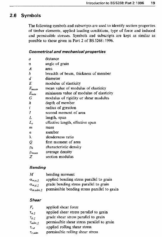
The following symbols and subscripts are used to identify section properties of timber elements, applied loading conditions, type of force and induced and permissible stresses. Symbols and subscripts are kept as similar as possible to those given in Part 2 of BS 5268 : 1996.
~eometrical and mechanical properties
n a
A b d E Emean
Emjn G h l
I L L e m n h e Pk Prnean z
distance angle of grain area breadth of beam, thickness of member diameter modulus of elasticity mean value of modulus of elasticity minimum value of modulus of elasticity modulus of rigidity or shear modulus depth of member radius of gyration second moment of area length, span effective length, effective span mass number slenderness ratio first moment of area characteristic density average density section modulus
bending moment applied bending stress parallel to grain grade bending stress parallel to grain permissible bending stress parallel to grain
applied shear force applied shear stress parallel to grain grade shear stress parallel to grain permissible shear stress parallel to grain applied rolling shear stress pernhssible rolling shear stress

28 Structural Timber Design
A m bending deflection A s shear deflection Atotal total deflection due to bending and shear A,& permissible deflection
CF,,,,~/ applied compressive stress parallel to grain
C T , , , ~ , / / permissible compressive stress parallel to grain CF , , , ,~ applied compressive stress perpendicular to grain o,lg,l grade compressive stress perpendicular to grain C F ~ , , ~ , ~ permissible compressive stress perpendicular to grain
O,,g, I/ grade compressive stress parallel to grain
Tension
C F ~ , ~ , / I applied tensile stress parallel to grain
a t l U ~ , ~ ~ permissible tensile stress parallel to grain CJt1g,// grade tensile stress parallel to grain
1. Arya, C. (1994) Design of structural elements. E. & F. N. Spon, London. 2. British Standards Institution (1984, 1995, 1988) BS 6399: Loading for buildings.
Part 1 : 1984 : Code of practice for dead and imposed loa&. Part 2 : 1995 : Code of practice for wind loa&. Part 3 : 1988 : Code of practice for imposed roof loads. BSI, London.
3. British Standards Institution (1972) CP 3 : Chapter V : Loading. Part
4. British Standards Institution (1995) BS EN 336 : Structural timber. Coniferous 2 : 1972 : Wind loads. BSI, London.
and poplar. Sizes. Permissible deviations. BSI, London.
apter
Many academic institutions and design offices are turning to computer assisted instructions. This is especially true in science and engineering where courses are being introduced to teach the use of computers as analysis and design tools. Mathcad’s potential as a powerful and easy to use compu- tational tool has already been recognised by most academic institutions and many design offices.
The aim of this chapter is to demonstrate how the analysis and design calculations for structural timber can be incorporated into simple-to-use electronic notepads or worksheets. Access to a personal computer (PC) and the associated software Mathcad is not a prerequisite for understanding the design calculations in the examples provided in this book. All design examples given are fully self-explanatory and well annotated. They have been produced in the form of worksheets to run under Mathcad, version 6, or higher, in either one of its editions, i.e. Student, Standard, Plus or Professional. Details are given at the end of this book.
The design worksheets given are intended as a source of study, practice and further development by the reader. They should not be seen as complete and comprehensive design worksheets but rather as the foundations of a design system that can be developed further. The aim is to encourage readers to use computing as a tool to increase their understanding of how design solutions vary in response to a change in one of the variables and how alter- native design options can be obtained easily and effortlessly, allowing the design engineer to arrive at the most suitable/economic solution very quickly.
It is important to note that this chapter is not intended to teach Mathcad. It aims only to familiarise the reader with the Mathcad worksheet formats that are used to produce design examples in this book.
Mathcad (developed by MathSoft, Inc.) is an electronic notepad (live worksheet) that allows ath he ma tical calculation to be performed on a
21

22 Structural Timber Design
3.3
computer screen in a format similar to the way it would be done manually with paper and pencil. While Mathcad employs the usual mathematical symbols (i.e. +, -, /, =) for algebraic operations, it also uses the conven- tional symbols of calculus for differentiation and integration to perform these operations. It preserves the conventional symbolic form for subscrib- ing, special mathematical and trigonometrical functions, series operations, and matrix algebra. When expository text is added, Mathcad’s symbolic format leads to reports that are understood easily by others. Data can be presented in both tabular and graphical forms.
Mathcad can also be used to answer, amongst many others, the ‘what-if’ questions in engineering problems. With a well structured worksheet, design calculations can be performed whereby parameters can be changed and the results viewed almost immediately on the computer display and/or printed.
What does Mathcad do?*
Mathcad combines the live document interface of a spreadsheet with the WYSIWYG interface of a word processor. With Mathcad, equations can be typeset on the screen in exactly the way they are presented in textbooks, with the advantage that it can also do the calculations.
Mathcad also comes with multiple fonts and the ability to print what you see on the screen on any Windows supported printer. This, combined with Mathcad’s live document interface, makes it easy to produce up-to-date, publication-quality engineering reports and/or design solution sheets.
The following subsections demonstrate how some simple operations are carried out in Mathcad. This is to illustrate the formatlmeaning of the operations used to produce the examples in this text.
3.3.1 A simple calculation’
Although Mathcad can perform sophisticated mathematics, it can just as easily be used as a simple calculator. For example,
Click anywhere in the worksheet; you will see a small crosshair. Type 15 - 81104.5 =
As soon as the equal sign is pressed, Mathcad computes and shows the result (see Fig. 3.1).
3.3.2 Definitions and variables2
Mathcad’s power and versatility quickly becomes apparent when the vari- ables and functions are being used. By defining variables and functions, equations can be linked together and intermediate results can be used in further calculations.

Using Mathcad for Design Calculations 23
15"- - 14.923 \
Fig. 3.1 A simple calculation.
For example, to define a value of say 10 to a variable, say t, click anywhere in the worksheet and type t: (the letter t followed by a colon). Mathcad will show the colon as the definition symbol := and will create an empty place holder to its right. Then type 10 in the empty placeholder to complete the definition for t.
To enter another definition, press ["I] to move the crosshair below the first equation. For example, to define ace as -9.8, type acc:-9.8. Then press [ J] again.
Now that the variables ace and t are defined, they can be used in other expressions. For example, to calculate the magnitude of - t 2 type acc/ 2*tA2. The caret symbol A represents raising to a power, the asterisk * is multiplication, and the slash / is division,
To obtain the result, type =. Mathcad will return the result (as shown in Fig. 3.2).
ace 2
acc :=-g%
Fig. 3.2 Calculating with variables and functions.

24 Structural Timber Design
acc :=-9.8
Fig. 3.3 Entering text.
Mathcad handles text as easily as it does equations. To begin typing text, click in an empty space and choose Create Text %ion from the Text menu or simply click on the icon on the menu bar. Mathcad will then create a text box in which you can type, change font, format and so on as you would when using a simple Windows based word processor. The text box will grow as the text is entered.
Now type, say, ‘Equation of motion’ (see Fig. 3.3). To exit text mode simply click outside the text box.
Units of measurement, while not required in Mathcad equations, can help detect and enhance the display of computed results. Mathcad’s unit capa- bilities take care of many of the usual chores associated with using units
M = 20 *kN.m
Fig. 3.4 Equations using units.

Using Mathcad for Design Calculations 25
and dimensions in engineering analysis and design calculations. Once the approp~ate definitions are entered, Mathcad automatically performs unit conversions and flags up incorrect and inconsistent dimensional calculations.
Although Mathcad’s latest edition recognises most common units, you may wish to define your own units. For example, N =newton, and kN = IO3 N. To assign units to a number, simply multiply the number by the name or letter(s) which defines the unit.
To illustrate this, calculate the magnitude of the bending moment M at the built-in end of a cantilever of length L = 2m induced by a force of P = 10 kN acting at its free end. To do this, click anywhere in a worksheet and type:
N :=newton kN := 103*N L := 2*m P := 1O*kN M := P*L
Then type M=. As soon as the = sign is typed, Mathcad will compute the result and also display the units of M (as shown in Fig. 3.4).
The previous examples aimed to demonstrate the simplicity of using Mathcad in producing the design examples given in the proceeding chapters of this book. To learn more about Mathcad, refer to the next section in this chapter.
1. Wieder, S. (1992) Introduction to ~ u t h c u d for Scientists and Engineers. McGraw-
2. ~ a t ~ c a d User’s Guide, ~ a t h c u d 6.0 (1996) Mathsoft, Inc., MA. Hill, Inc., Hightstown.

Flexural members are those subjected to bending. There are several types and forms of flexural timber members that are used in construction. Typical examples are solid section rectangular beams, floor joists, rafters and purlins. Other examples include glulam beams (vertical and horizontal glued laminated beams), ply-webbed beams (I-beams and box-beams) and beams of simple composites (Tee and I shaped beams).
Although the design principles are essentially the same for all bending members of all materials, the material characteristics are different. Steel for example is ductile, homogeneous, and isotropic. Concrete is brittle and can be assumed homogeneous for most practical purposes. A s for timber, the material properties are different in the two main directions: parallel and perpendicular to the grain. Even though the normal stresses due to bending are parallel to grain direction, support conditions may impose stresses that are perpendicular to grain direction. These stresses, in addition to the primary stresses, should be checked in the design against the permissible values, which include the effects of environmental conditions, material and geometrical characteristics.
This chapter deals in detail with the general considerations necessary for the design of flexural members and describes the design details of solid section rectangular timber beams. Design methods for glued laminated beams and ply-webbed beams are described in Chapters 6 and 7 , respectively.
The main design considerations for flexural members are:
(1) bending stress and prevention of lateral buckling (2) deflection (3) shear stress (4) bearing stress.
26

Design of Flexural Members (Beams) 27
The cross-sectional properties of all flexural members have to satisfy elastic strength and service load requirements. In general, bending is the most critical criterion for medium-span beams, deflection for long-span beams and shear for heavily loaded short-span beams. In practice, design checks are carried out for all criteria listed above.
In Chapter 2 it was mentioned that the design of timber elements, connec- tions and components is based on the recommendations of BS 5268 : Part 2 : 1996 which is still based on 'permissible stress' design philosophy. The per- missible stress value is calculated as the product of the grade stress and the appropriate modification factors for particular service and loading condi- tions, and is usually compared with the applied stress in a member or part of a component in structural design calculations. In general:
permissible stress (= grade stress x K-factors ) 2 applied stress
4.3 Bending stress and prevention of lateral buckling
The design of timber beams in flexure requires the application of the elastic theory of bending as expressed by:
1M.Y I
ff=-
The term Z/y is referred to as section modulus and is denoted by Z. Using the notations defined in Chapter 2, the applied bending stress about the major (x") axis of the beam (say) (see Fig. 4.1), is calculated from:
I 1
Y Fig. 4.1 Cross-section of a rectangular beam,

28 Structural Timber Design
where: amla,// = applied bending stress (in N/mm2)
M= maximum bending moment (in Nmm) Zxx= section modulus about its major (x-x) axis (in mm3). For rect-
angular sections
bh3
2 Ixx= second moment of area about x-x axis (in mm4) y= distance from the neutral-axis of the section to the extreme fibres
h= depth of the section (in mm) b = width of the section (in mm).
(in mm)
The permissible bending stress amla&,// is calculated as the product of grade bending stress parallel to grain am,g,// and any relevant modification factors (K-factors). These are K2 for wet exposure condition (if applicable), K3 for load-duration, K6 for solid timber members other than rectangular sections (if applicable), KT for solid timber members other than 300mm deep, and K8 for load-sharing systems (if applicable). Hence:
am,adm,//= Om,g,// x K2 x K3 x K6 x K1 x Kt3 (4.4) KZ? K3 and K8 are general modification factors, which were described in detail in Chapter 2. K6 and K-, specifically relate to the calculation of permissible bending stress, am,a&,// and are described in the following sections.
Clause 2.10,3 of BS 5268 : Part 2 recommends that the span of flexural members should be taken as the distance between the centres of bearings.
Required bearing length
Beam or joist
Clear span Effective span Span to centres of actual bearings
I i
ig. 4.2 Effective span (Baird and Ozelton').
Design of Flexural Members (Beams) 29
Where members extend over bearings, which are longer than is necessary, the spans may be measured between the centres of bearings of a length which should be adequate in accordance with Part 2 of the code (see Fig. 4.2).
In determining the effective span, Le, it is usually acceptable to assume an addition of 50 mm to the clear span, between the supports, for solid timber beams and joists and 100 mm for built-up beams on spans up to around 12 m, but longer spans should be checked.'
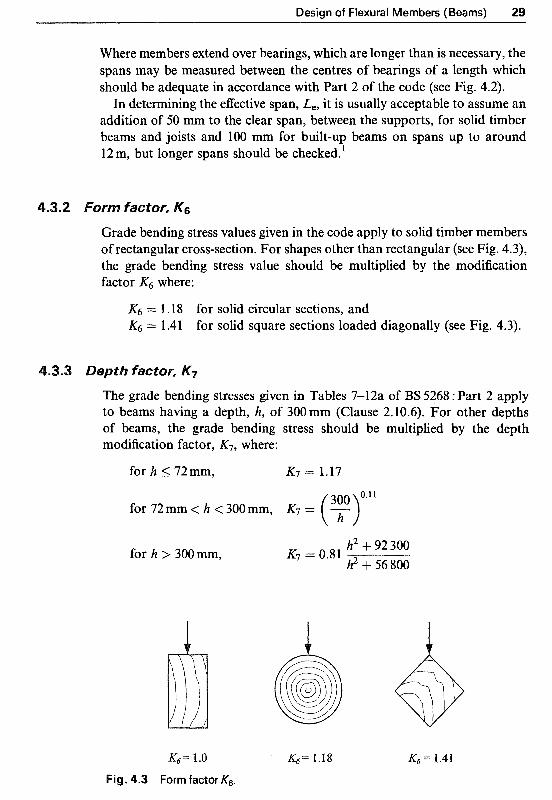
Grade bending stress values given in the code apply to solid timber members of rectangular cross-section. For shapes other than rectangular (see Fig. 4.3), the grade bending stress value should be multiplied by the modification factor K6 where:
&j = 1.18 for solid circular sections, and = 1.41 for solid square sections loaded diagonally (see Fig. 4.3).
The grade bending stresses given in Tables 7-12a of BS 5268 : Part 2 apply to beams having a depth, h, of 300 mm (Clause 2.10.6). For other depths of beams, the grade bending stress should be multiplied by the depth modification factor, K7, where:
for h 5 72mm, K7 = 1.17
for 72mm h < 300mm, K7 = ( ~ ~ . l l
for h 300mm, h2 + 92 300 h2 + 56 800
K7 = 0.81
K:,= 1.0 K4= 1.18 K4= 1.41
Fig. 4.3 Form factor KG.

30 Structural Timber Design
4.3.4 Selection of a suitable section size
There are two methods commonly used in selecting an appropriate trial section:
(1) Engineering judgement which is based on experience. (2) By utilising the permissible bending stress criterion in equation (4.2).
Thus the expression for calculation of the required section modulus Zxx for timber members, incorporating all the relevant K-factors, is as follows:
Thus a suitable section size having a Zxx 2 Zxx,required can be selected. The chosen section should then be checked for lateral stability, deflection, shear and bearing.
The standard (customary) sizes of timber sections in the UK, normally available from stock, are given in the National Annex to BS EN 336. A sum- mary of details is given in Appendix A.
4.3.5 Lateraf stability
BS 5268 : Part 2 : 1996 recommends that the depth to breadth ratio of solid and laminated rectangular beams should not exceed the values given in
Table 4.1 Maximum depth to breadth ratio for solid and laninated members, (Table 16, BS 5268 : Part 2)
Degree of lateral support Maximum depth to breadth ratio
No lateral support 2
Ends held in position 3
Ends held in position and member held in line as by 4 purlins or tie rods at centres not more than 30 times breadth of the member
Ends held in position and compression edge held in line, 5 as by direct connection of sheathing, deck or joists
Ends held in position and compression edge held in line, 6 as by direct connection of sheathing, deck or joists, together with adequate bridging or blocking spaced at intervals not exceeding 6 times the depth
Ends held in position and both edges held firmly in line 7

Design of Flexural Members (Beams) 31
(a) Solid blocking
(b) Skewed blocking
(c) Herring bone strutting (bridging)
Fig. 4.4 Examples of provisions for lateral support.
Table 16 (reproduced here as Table 4.1) of the code corresponding to the appropriate degree of lateral support. Examples of provisions for lateral support are shown in Fig. 4.4.
4.3.6 An iJJustrative exampJe
Determine the value of permissible bending stress parallel to grain and magnitude of maximum bending moment for a main beam of 50mm x 200 mm deep Canadian Douglas fir-larch grade SS under service class 2 and short-duration loading.

32 Structural Timber Design
BS 5268 : Part 2 Description output
Table 2 strength classification strength class = C24 Table 7 grade stress // to grain gm,g,// = 7.5 N/mm2 Clause l .6.4 service class 2 K2 ~=ll 1 Table 14 short-duration loading K3 = 1.5 Clause 2.10.5 rectangular section = 1
Clause 2.10.6 depth factor 0.11
K7 = (g) = 1.045
Clause 2.9 no load-sharing Kg = l
Permissible bending stress
Allowable maximum bending moment is obtained by rearranging equation (4.5)
M = 3.91 kNm
4.4 Deflection
BS 5268 : Part 2, Clause 2.10.7 recommends that ‘The dimensions of flexural members should be such as to restrict deflection within limits appropriate to the type of structure, having regard to the possibility of damage to surfacing materials, ceilings, partitions and to the functional needs as well as aesthetic requirements.’
4.4.1 Deflection limits
In most cases, including domestic flooring, the combined deflection due to bending, Am, and shear, As, should not exceed 0.003 of the span to satisfy this r~commendation. In addition, for domestic floor joists, the deflection under full load should not exceed the lesser of 0.003 times the span or 14mm. This is to avoid undue vibration under moving or impact loading.
In general A t o t a l = (Am + A,) 5 (0.003 X span)
and for domestic joists Atotal 5 lesser of (0.003 x span or 14 mm)

Design of Flexural Members (Beams) 33
4.4.2 ~ r e c a ~ ~ e r
Subject to consideration being given to the effect of excessive deformation, timber beams may be precambered to account for the deflection under full dead or permanent load. In this instance, BS 5268 : Part 2 recommends that the deflection due to imposed load only should not exceed 0.003 of the span.
4.4.3 Bending deflection
The maximum bending deflection induced by the two most common load cases is given below:
(1) For a simply supported beam carrying a uniformly distributed load of wtotal
5 wtotalL3 Am = 384EI (2) For a simply supported beam carrying a concentrated load at mid-span
of P
PL3 Am =- 48EI (4.7)
where: I/V;otal= total uniformly distributed load
P = concentrated load acting at mid-span L = effective span I= second moment of area about axis of bending, usually beam’s
E = Emh for a beam acting on its own major (x+ axis
= Emean for a beam in a load-sharing system.
For a single-span simply supported beam subjected to a maximum bending moment of Mm,, irrespective of the loading type, the maximum deflection of the beam may be estimated using:
0.1 O4Mmx L2 EI
A, cli

34 Structural Timber Design
Table 4.2 Modification factor Kg used to modify the minimum modulus of elasticity for trimmer joists and lintels (Table 17, BS 5268 : Part 2)
Number of pieces Value of Kg
Softwoods Hardwoods
l 2 3 4 or more
1 .oo 1.14 l .21 1.24
1 .oo 1.06 1.08 1.10
Note: BS 5268 : Part 2, Clause 2.10.1 1 recommends that for trimmer joists and lintels which comprise two or more pieces connected together in parallel and acting together to support the loads, the minimum modulus of elasticity modified by the modification factor Kg, given in Table 17 of the code, should be used for calculation of deflections. Table 17 is reproduced here as Table 4.2.
4.4.4 Shear def/ection
Since in timber and wood based structural materials the shear modulus is considerably lower as a proportion of the modulus of elasticity, compared to other structural materials such as steel, the effect of shear deflection can be significant and should be considered in the design calculations.
The maximum shear deflection, A,, induced in a single-span simply supported beam of either rectangular or square cross-section, may be determined from the following equation:
where A is the cross-sectional area of the beam, M,, is the maximum bending moment in the beam and E is as defined above.
4.5 Bearing stress
The bearing stresses in timber beams are developed due to compressive forces applied in a direction perpendicular to the grain and occur in positions such as points of support or applied concentrated loads. Possible bearing failure positions are shown in Fig. 4.5.
The applied bearing stress, CT,,~,J is calculated from the following equation:
(4.10)
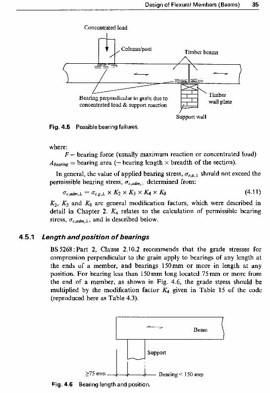
Design of Flexural Members (Beams) 35
Concentrated load
Timber beams
Support wall Fig. 4.5 Possible bearing failures.
where:
Abeuring = bearing area (= bearing length x breadth of the section). F = bearing force (usually maximum reaction or concentrated load)
In general, the value of applied bearing stress, C T ~ , ~ , ~ should not exceed the permissible bearing stress, C T ~ , , ~ , ~ determined from:
~ c , u d m , L = Qc,g,L x K2 x K3 x K4 x K8 (4.1 1) K,, K3 and & are general modification factors, which were described in detail in Chapter 2. K4 relates to the calculation of permissible bearing stress, C T ~ , ~ & , ~ , and is described below.
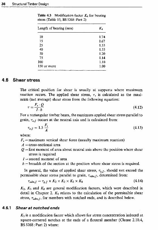
4.5.1 Length and position of bearings
BS 5268 : Part 2, Clause 2.102 recommends that the grade stresses for compression perpendicular to the grain apply to bearings of any length at the ends of a member, and bearings 150mm or more in length at any position. For bearing less than 150 mm long located 75 mm or more from the end of a member, as shown in Fig. 4.6, the grade stress should be multiplied by the modification factor K4 given in Table 15 of the code (reproduced here as Table 4.3).
375 m Bearing 150 m
Fig. 4.6 Bearing length and position.
36 Structural Timber Design
Table 4.3 Modification factor K4 for bearing stress (Table 15, BS 5268 : Part 2)
Length of bearing (mm) K4
10 15 25 40 50 75
100 150 or more
1.74 l .67 1.53 l .33 1.20 1.14 1.10 l .oo
ear stress
The critical position for shear is usually at supports where reaction occurs. The applied shear stress, r, is calculated as mum (not average) shear stress from the following equation:
maximum the maxi-
(4.12)
For a rectangular timber beam, the maximurn applied shear stress parallel to grain, ra,j occurs at the neutral axis and is calculated from:
r;, Tal// = 1.5 - A (4.13)
where: Fv = maximum vertical shear force (usually maximum reaction) A = cross-sectional area Q = first moment of area about neutral axis above the position where shear
stress is required I = second moment of area b = breadth of the section at the position where shear stress is required. In general, the value of applied shear stress, Tal//, should not exceed the
Permissible shear stress parallel to grain, rahI/, determined from: Tu&,// = rg , / / X K2 X K3 X K5 X (4.14)
&, K3 and K8 are general modification factors, which were described in detail in Chapter 2. K5 relates to the calculation of the permissible shear stress, rahI/, for members with notched ends, and is described below.
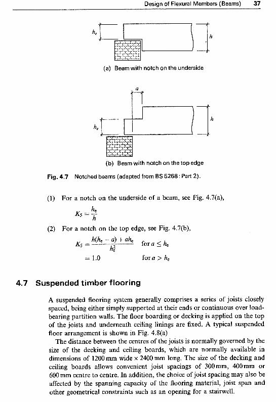
ear at notched ends
K5 is a modification factor which allows for stress concentration induced at square-cornered notches at the ends of a flexural member (Clause 2.10.4, l3S 5268 : Part 2) where:
Design of Flexural Members (Beams) 37
\ 4 (a) Beam with notch on the underside
I I
(b) Beam with notch on the top edge
Fig. 4.7 Notched beams (adapted from BS 5268: Part 2).
(1) For a notch on the underside of a beam, see Fig. 4.7(a),
(2) For a notch on the top edge, see Fig. 4.7(b),
= 1.0 fora > he
uspended timber flooring
A suspended flooring system generally comprises a series of joists closely spaced, being either simply supported at their ends or continuous over load- bearing partition walls. The floor boarding or decking is applied on the top of the joists and underneath ceiling linings are fixed. A typical suspended floor arrangement is shown in Fig. 4.8(a)
The distance between the centres of the joists is normally governed by the size of the decking and ceiling boards, which are normally available in dimensions of 1200 mm wide x 2400mm long. The size of the decking and ceiling boards allows convenient joist spacings of 300 mm, 400mm or 600mm centre to centre. In addition, the choice of joist spacing may also be afYected by the spanning capacity of the flooring material, joist span and other geometrical constraints such as an opening for a stairwell.

38 Structural Timber Design
Joists Header joist
Header joist Trimer Stairwell joists A
(a) A typical suspended floor arrangement
10 m bolts staggered at 600 m centres
(d) Flitched beam
6 to 1 O m thick steel plate, 10 m less in depth than timber joists
Joists
Masonry wall
Trimer joists C
\ Tongued & grooved boarding
\ Load-bearing partition wall & spreader beam
Joists
Joists
38 or 50 mm
(b) Solid timber tongued & grooved decking
Trimer joists Joist-hanger nailed together
(c) A typical joist to t r imer joists connection
Solid blocking v
between joists Masonry wall
(e) A typical support arrangement
Fig. 4.8 Suspended timber flooring - typical components.

Design of Flexural Members (Beams) 39
The most common floor decking in domestic dwellings and timber-framed buildings uses some form of wood-based panel products, for example chipboard or plywood. Solid timber decking such as softwood tongued and grooved (t & g) decking is often used in roof constructions, in conjunction with glued-laminated members, to produce a pleasant, natural timber ceiling with clear spans between the main structural members. The solid timber tongued and grooved boards are normally machined from 150 mm wide sections with 38-75 mm basic thicknesses [Fig. 4.8(b)].
The supports for joists are provided in various forms depending on the type of construction. Timber wall plates are normally used to support joists on top of masonry walls and foundations, Fig. 4.8(e). In situations where joists are to be supported on load-bearing timber-frame walls or internal partitions, header beams or spreader members are provided to evenly distribute the vertical loads. Joist-hangers are often used to attach and support joists onto the main timber beams, trimmer members or masonry walls [Fig. 4.8(c)].
Timber trimmer joists are frequently used within timber floors of all types of domestic buildings, see Fig. 4.8(a). There are two main reasons for which trimmer joists may be provided2. First is to trim around an opening such as a stairwell or loft access (Trimmer joists A), and to support incoming joists (Trimmer joists B), and second is to reduce the span of floor joists over long open spans (Trimmer joists C), as shown in Fig. 4.8(a).
Trimming around openings can usually be achieved by using two or more joists nailed together to form a trimmer beam, Fig. 4,8(c), or by using a single but larger timber section if construction geometry permits. Alternatively, trimmers can be of hardwood or glued laminated timber, boxed ply-webbed beams, or composite timber and steel flitched beams2, Fig. 4.8(d).
All flooring systems are required to have fire resistance from the floor below and this is achieved by the ceiling linings, the joists and the floor boarding acting together as a composite construction3. For example, floors in two storey domestic buildings require modified 30 minutes fire resistance (30 minutes load-bearing, 15 minutes integrity and 15 minutes insulation). In general a conventional suspended timber flooring system comprising 12.5 mm plasterboard taped and filled, tongued and grooved floor boarding with at least 16mm thickness directly nailed to floor joists, meets the requirements for the modified 30 minutes fire resistance provided that where joist-hangers are used they are formed from at least 1 mm thick steel of strap or shoe type. Further details and specific requirements for fire resistance are given in BS 5268 : Part 4: ‘Fire resistance of timber structures’.
4.8 References
1. Baird and Ozelton (1984) Timber Designer’s Munual, 2nd edn. BSP Professional Books, Oxford.
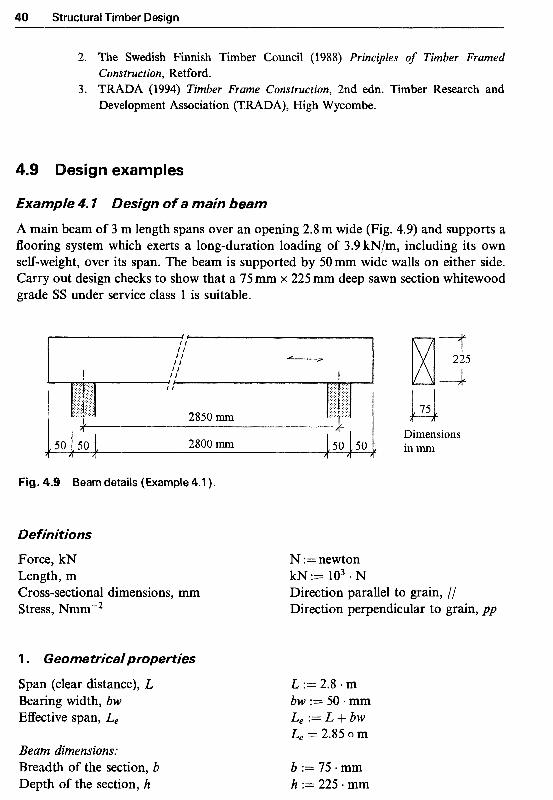
40 Structural Timber Design
2. The Swedish Finnish Timber Council (1988) Principles of Timber Framed
3. TRADA (1994) Timber Frame Construction, 2nd edn. Timber Research and Construction, Retford.
Development Association (TRADA), High Wycombe.
4.9 Design examples
Example 4 7 Design of a main beam
A main beam of 3 m length spans over an opening 2.8 m wide (Fig. 4.9) and supports a flooring system which exerts a long-duration loading of 3.9 kN/m, including its own self-weight, over its span. The beam is supported by 50mm wide walls on either side. Carry out design checks to show that a 75 mm x 225 mm deep sawn section whitewood grade SS under service class 1 is suitable.
Fig. 4.9 Beam details (Example 4.1 ).
Definitions
Force, kN Length, m Cross-sectional dimensions, mm Stress, Nmm"2
'1. Geometrical properties
Span (clear distance), L Bearing width, bw Effective span, Le
Beam di~ensi5ns: Breadth of the section, b Depth of the section, h
Dimensions inmm
N := newton kN:= lo3 .N Direction parallel to grain, // Direction perpendicular to grain, pp
L := 2.8 m bw := 50-mm Le := L+bw Le = 2.85 o m
b := 75. mm h := 225. mm

Design of Flexural Members (Beams) 41
Cross-sectional area, A
Second moment of area, Z,,
A : = b * h A = 16 875 o mm2
Zxx = 7.12 x lo7 o mm4 Zxx := h. b * h3
2. Loading
Applied uniformly distributed load, W W := 3.9 kN m-* Total load, W W : = w e L e
W = 11.11 okN
3. K-factors
Service class 1 (K2, Table 13) Load duration (&, Table 14) Bearing: 5 0 m , but located < 75 mm
from end of member (K4, Table 15) Notched end effect (K5, Clause 2.10.4) Form factor (&, Clause 2.10.5)
Depth factor (K7, Clause 2.10.6)
No load sharing (Kg, Clause 2.9)
4. Grade stresses
BS5268 : Part 2, Tables 2 and 7 Whitewood grade SS Bending parallel to grain Compression perpendicular to grain Shear parallel to grain Minimum modulus of elasticity
5 . Bending stress
Applied bending moment
Section modulus
Applied bending stress
K2 := l
:= 1 K3 := 1 for long-term
K5 := 1 for no notch
300 mm '*l1 K6 := 1
K7 := ( h ) K7 = 1.03 K8 := 1
Strength class = C24 am.g.l/ := 7.5 - N * mm-2
rg.I := 0.71 + N - mm"2 := 2.4 N + mm-2 no wane
Emin := 7200 * N * mm-2
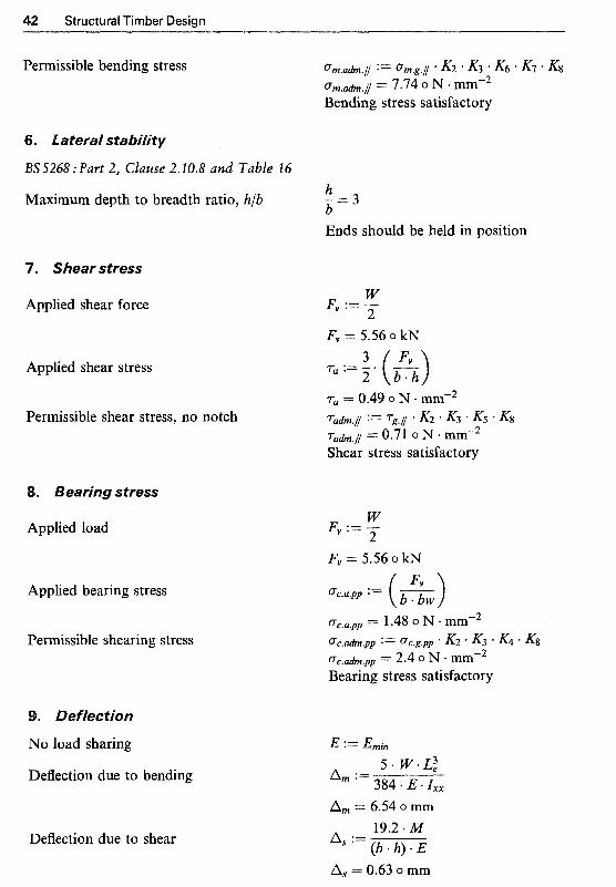
42 Structural Timber Design
Permissible bending stress 0m.adm.// := 0 m . g . j * K2 K3 K6 * K1 ' K8 crrn.,h.l = 7.74 o N mm-2 Bending stress satisfactory
6. Lateral stability
BS S268 :Part 2, Clause 2.20.8 and Table 16
Maximum depth to breadth ratio, h/b - -=3 h b Ends should be held in position
7. Shear stress
Applied shear force W Fv L
F,, = 5.56 o kN 3
2 Applied shear stress l.,:=-- (A)
Permissible shear stress, no notch 7adm.j :Irz 7 g . l * K2 K3 * K5 *
Ta = 0.49 o N * mm"2
Tadm.j = 0.71 o N * mm-2 Shear stress satisfactory
8. Bearing stress
Applied load
Applied bearing stress
Permissible shearing stress
9. Deflection
No load sharing
Deflection due to bending
Deflection due to shear
W Fv :=- 2
Fv = 5.56 o kN
a,.,, = 1.48 o N mm-2 0c.adm.pp := ac.g.pp K2 * K3 K4 ' K8 (7c.adm.pp = 2.4 o N - mm-2 Bearing stress satisfactory
A, = 6.54 o mm
As := 19.2 * M (l? * h) E
A, = 0.63 o mm

Design of Flexural Members (Beams) 43
Total deflection
Permissible deflection
AItotal := A m + A s AtOtal = 7.16 0 mm Aadm := 0.003 Le Aadm = 8.55 0 mm Deflection satisfactory
Therefore a 75 mm x 225 mm sawn section whitewood C24 is satisfactory
Example 4.2 Design of floor joists
A timber floor spanning 3.8 m centre to centre is to be designed using timber joists at 400 mm centres. The floor is subjected to a domestic imposed load of 1 .S kN/m2 and carries a dead loading, including self-weight of 0.35 kN/m2. Carry out design checks to show that a series of 44mm x 200mm deep sawn section British spruce grade SS under service class 1 is suitable.
Joist han er
Main beam
Tongued & grooved boarding Y
X" ~ "X
Y
Section A-A
Fig. 4.1 0 Timber floor joists (Example 4.2).
Definitions
Force, kN Length, m Cross-sectional dimensions, mm Stress, Nmm-2
1. Geometricaiproperties
Cross-section
N := newton
Direction parallel to grain, // Direction perpendicular to grain, pp
kN :==: lo3 * N
Effective span, Le Joist spacing, Js
L e := 3.8 * m Js := 0.4. m
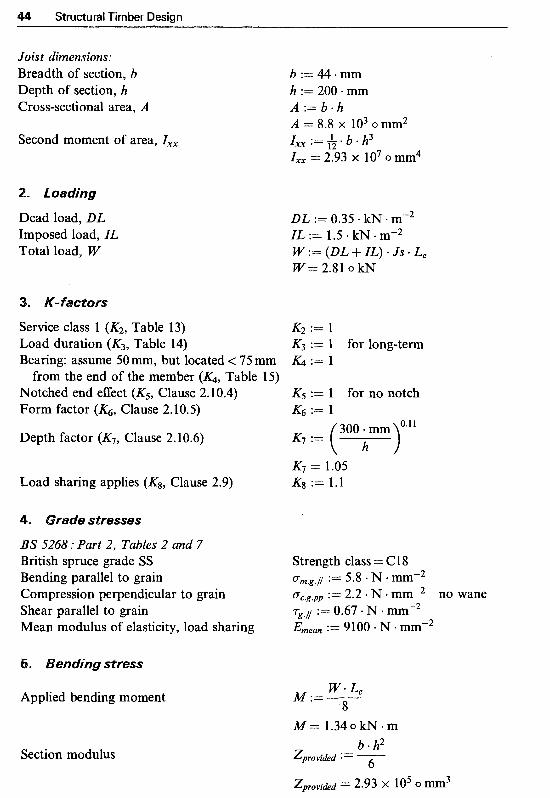
Structural Timber Design
Joist d i ~ e n ~ i ~ n s ~ Breadth o f section, b Depth o f section, h Cross-sectional area, A
Second moment o f area, Zxx
Dead load, DL Imposed load, ZL Total load, W
Service class 1 (KZ, Table 13) Load duration (K3, Table 14) Bearing: assume 50 mm, but located < 75 mm
from the end o f the member (K& Table 15) Notched end eEect (Ks, Clause 2.10.4) Form factor (K& Clause 2.10.5)
Depth factor (K7, Clause 2.10.6)
Load sharing applies (Kg, Clause 2.9)
BS 5268 : Part 2, Tables 2 and 7 British spruce grade SS Bending parallel to grain Compression perpendicular to grain Shear parallel to grain Mean modulus o f elasticity, load sharing
Applied bending moment
Section modulus
b := 44 mm h := 200 mm A := b * h A = 8.8 X lo3 0 mm2 Zxx := * b * h3 Zxx = 2.93 x lo7 o mm4
DL := 0.35 - kN m-2 IL := 1.5 kN m-2 W : = ( D L + I L ) * J S * L e W = 2.81 o kN
K2 := 1 K3 := 1 for long-term & := 1
K5 := 1 for no notch
300 mm '.l1
K6 := 1
'= ( h ) K7 = 1.05 Kg := 1.1
Strength class = C 18 o - ~ . ~ . N := 5.8 N mm-2 o - ~ . ~ . , ~ := 2.2 . N ,mm-2 no wane 7--.1 := 0.67. N mmm2 Emean := 9 100 * N + mm"2

Design of Flexural Members (Beams)
Applied bending stress
Permissible bending stress
6. ~ate~at s t a ~ i ~ i ~
BS5268 : Part 2, Clause 2.10.8, and Table 16
Maximum depth to breadth ratio, h/b - = 4.55 h b Ends should be held in position and compression edges held in line
7. ~ ~ e a p stress
Applied shear force
Applied shear stress
Permissible shear stress, no notch
Applied load
Assume bearing widths, bw, o f 50mm either side
Applied bearing stress
Permissible bearing stress
W -F, := -y- L.
.Fv = 1.41 o kN
W r;, := - 2

46 Structural Timber Design
9. ~ef fe~t ion
Load sharing system
Deflection due to bending
Deflection due to shear
Total deflection
Permissible deflection
Am = 7.53 o mm
A, := 19.2 * A4 (b * h) * E
A, = 0.32 o mm
Atotal = 7.85 o mm
A u h = 11.4 o mm Deflection satisfactory
Atotal := a m + A s
:= 0.003 * Le
Therefore 44 mm x 200 mm sawn sections in Cl8 timber are satisfactory
Example 4.3 Design of floor joists - sefection of a suitabfe section and design for notched ends
The cross-section of a suspended timber flooring system is shown in Fig. 4.1 1. It con- sists of tongued and grooved (t & g) boarding with a self-weight of 0.15 kN/m2 and carries a plasterboard ceiling of 0.2 kN/m2. The floor has an effective span of 4.0 m and is subjected to a domestic imposed load of 1.5 kN/m2. Design the timber floor joists using timber in strength class Cl 8 under service class 1.
If the joists are to be notched at bearings with a 72mm deep notch, check that the notched section is also adequate.
Tongued & grooved boarding \
Plasterboard Y
Notched joist
Fig. 4.1 1 Timber floor joists (Example 4.3).
I
Y
Cross-section

Design of Flexural Members (Beams) 47
Force, kN Length, m Cross-sectional dimensions, mm Stress, Nrnmw2
Effective span, Le Joist spacing, Js
Dead load: t & g boarding (kN/m2), tg Plasterboard ceiling (kN/m2), Pb Self-weight (kN/m2), Swt Imposed load (kN/m2), ZL Total load (kN), W
Service class 1 (KZ, Table 13) Load duration (K3, Table 14) Bearing (.K4, Table 15), assume Notched end effect (Ks, Clause 2.10.4)
Form factor (KG, Clause 2.10.5) Depth factor (K7, Clause 2.10.6) Load sharing applies (K8, Clause 2.9)
for no notch
N :=newton
Direction parallel to grain, // Direction perpendicular to grain, pp
k~ := 103 . N
L e := 4.0 * m Js := 0.45 m m
tg := 0.15 kN m-2 Pb := 0.2 kN m-2 Swt := 0.10 - kN mm2 assumed ZL := 1.5 kN - m-2 W : = ( t g + P b + S w t + Z L ) . J s . L , W = 3.51 o kN
K2 := 1 K3 := l for long-term & := 1 K5 := 1
:= 1 At this stage ignore KT K8 := 1.1
135'5268 : Part 2, Table 7 Strength class = C 18 Bending parallel to grain ".g.[ := 5.8 N mm"2 Compression perpendicular to grain oc.g.pp := 2.2 N .mm-2 no wane Shear parallel to grain := 0.6'7 N mm"2 Mean modulus of elasticity, load sharing Ernean := 9100 N * mm-2

Structural Timber Design
Applied bending moment
Bemissible bending stress
Required section modulus
BS5268: Part 2, Clause 2.10.8 and Table I6 In order to achieve lateral stability by direct fixing of decking to joists, the depth to breadth ratio should be limited to 5, i.e. h 5 5b. Substituting for h = 5b in Zxx = bh2/6 and equating it to Zrezuiredt gives:
b (5 * b)2 6 Zequired =
Thus, minimum breadth of section
and depth of section
b := ( 6 * zrequired 52
b = 40.42 o mm
h = 202.08 o mm h : = 5 * b
Selecting a trial section from Table A2, Appendix A. Try 47 mm x 200 mm deep section.
Beam dimensions Depth , h Breadth, b
Section modulus
Zprovihd = 3.13 X lo5 o mm3 300 mm '*''
~odification factor K7 for section depth K7 '= ( h )
Actual permissible bending stress Om.adm.1 := gm.g.1 ' K2 * K3 * K6 * K7 * K8 K7 = 1.05
cm.adm./l = 6.67 0 N * Bending stress satisfactory
Check se~-weight BS.5268 : Part 2, Table 7 Average density p := 380 kg. mW3 Total joist self-weight SWtactual := p * g * h * b L e
Assumed total self-weight SWtmsumed := SW5 * L e JS
SWtactual = 0.14 0 kN
s w t m s ~ e d = 0.18 0 kN Self-weight satisfactory


Structural Timber Design
Total deflection
Permissible deflection
Atotal := A m 4- A s Atotal = 10.65 o mm
nu& = 12omm Deflection satisfactory
Aa& := 0.003 * Le
~ere~ore 47 mm x 2 mm sawn ~ t i o n s in 618 tim~er are satisfacto~y
esign of a ~loor~ng system - f l o ~ r boards an
The ground floor of' a shop is to comprise a series of timber joists at 600 mm centres with tongued and grooved (t & g) boarding. The joists are simply supported on 100 mm hangers attached to load-bearing walls 4.2 m apart as shown in Fig. 4.12. Determine a suitable thickness for floor boarding using timber in strength class C18 and a suitable size for joists using timber in strength class C22 under service class 2. Assume imposed load is 2.0 kN/m'.
Joist hanger ued & grooved boarding
A flooring system for Example 4.4.
Force, kN Length, m Cross-sectional dimensions, mm Stress, NmmB2
N :=newton kN:= IO3 *N Direction parallel to grain, // Direction perpendicular to grain, pp
~~d ~ r o o v e ~ ~ o ~ r d i ~
To calculate flooring thickness boards may be designed as simply supported beams. Calculations need only be made for bending strength and deflection as span to thickness ratios and bearing widths are such that the shear and bearing stresses at supports are unlikely to be critical.
Assuming tongued and grooved boarding comprises 100 mm wide timber beams of thickness (depth) t simply supported on joists.

Design of Flexural Members (Beams) 51
1 . ~ e o ~ e t r i c a l properties
Joist spacing, JS Js := 0.6 . m Assume t & g boarding width, b b := 100 mm Effective span, L, Le := JS
2. ~oading
t & g boarding, tg Imposed load, IL Total load, W
3. K-factors
Service class 2 (K2, Table 13) Load duration (K3, Table 14) Bearing (K4, Clause 2.10.2) Notched end effect (KS, Clause 2.10.4) Form factor (K6, Clause 2.10.5) Depth factor (K7, Clause 2.10.6)
Load sharing applies (Kg, Clause 2.9) for h 5 72mm
tg := 0.1 kN + m"; IL := 2.0. kN - m-; W : = ( t g + I L ) * b . L e W = 0.13 o kN
K; := 1 K3 := 1 for long-term Kb, := 1 assumed K5 := 1 for no notch K4 := 1 K7 := 1.17
4. Grade stresses
BS.5268 : Part 2, Tables 2 and 7 Strength class = Cl 8 Bending parallel to grain := 5.8 + N - mmy2 Compression perpendicular to grain := 2 . 2 . N . mmv2 no wane Shear parallel to grain rg.I := 0.67 N - mm"; Mean modulus of elasticity, load sharing Ernean := 9 100 N * mmw2
5. Bending stress
Applied bending moment *- .- - W * Le
8
Permissible bending stress
Required thickness for t & g can be b * t 2 obtained by rearranging Z := - 6
t := ~ ' Zy'red , t = 8.72 0 mm
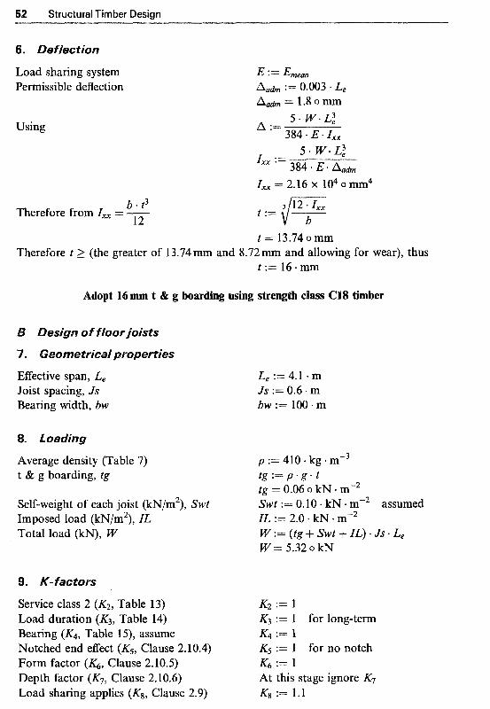
52 Structural Timber Design
6. ~eflectjon
Load sharing system Permissible deflection
Using
b * t3 12
Therefore from I,, = -
5 . W * L: I,, :=
rXx = 2.16 X io4 0mm4 384 E * A d m
t := {T 3 12 * I,,
t = 13.74 o mm
t := 16 * mm Therefore t 2 (the greater of .13.74mm and 8.72 mm and allowing for wear), thus
Adopt 16mm t & g boarding using strength class C18 timber
B ~ e s j ~ n of floor joists
7. ~ e o ~ e t r i ~ a l properties
Effective span, L, Joist spacing, Js Bearing width, bw
. Loa
Average density (Table 7 ) t & g boarding, tg
Self-weight of each joist (kN/m2), Swt Imposed load (kN/m2), IL Total load (kN), W
Service class 2 (K2, Table 13) Load duration (K3, Table 14) Bearing (K4, Table 15), assume Notched end effect (K5, Clause 2.10.4) Form factor (K6, Clause 2.10.5) Depth factor (K7, Clause 2.10.6) Load sharing applies (Ks, Clause 2.9)
L e 4.1 * m Js := 0.6 m bw := 100. m
p := 410 kg m-3 t g : = p * g * t tg = 0.06 o kN m-2 Swt := 0.10 - kN m-2 assumed ZL := 2.0 kN - W : = ( t g + S W t + I L ) * J S * L e W = 5.32 o kN
K2 := 1 K3 := 1 for long-term & := 1 K5 := 1 for no notch K6 := 1 At this stage ignore K? Kg := 1.1

Design of Flexural Members (Beams)
BS5268 : Part 2, Table 7 Strength class = C22 Bending parallel to grain Compression pe~endicular to grain Shear parallel to grain Mean modulus of elasticity, load sharing
Applied bending moment
Permissible bending stress
Required section modulus
amSg.1 := 6.8 N + mm-2 oc.g.pp := 2.3 .N -mm-2 no wane ~~1 := 0.71 N . Emem := 9700 * N * mm"2
BS5268: Part 2, Clause 2.10.8 and Table 16 In order to achieve lateral stability by direct fixing of decking to joists, the depth to breadth ratio should be limited to 5, i.e. h 5 5b. Substituting for h = 5b in Zxx = bh2/6 and equating it to Zrequired, gives:
b * (5 * b)2 zrequired = 6
Thus, minimum breadth of section b := ( 52 )l'? 6 * zrequired
and depth of section b=44.4omm h : = 5 * b h = 222.02 o
Selecting a trial section from Table A2, Appendix A. Try 47 mm x 225 mm deep section.
Beam dimensions Depth, h Breadth, b
Section modulus
h := 225. mm b := 47 - mm
b * h2 zprovided := - 6
K7 = 1.03
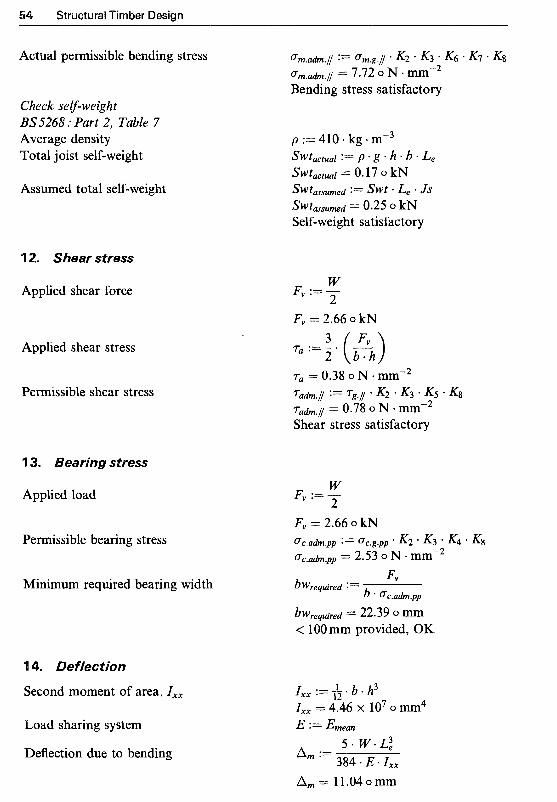
4 Structural Timber Design
Actual permissible bending stress
Check S~~-weight BS5268 : Purt 2, Tuble 7 Average density Total joist self-weight
Assumed total self-weight
12. Shear stress
Applied shear force
Applied shear stress
Permissible shear stress
13. ~ e a ~ j ~ ~ stress
Applied load
Permissible bearing stress
Minimum required bearing width
1 4. ~ e f f e c t i o ~
Second moment o f area, I,.
Load sharing system
Deflection due to bending
W Fv := - 2 Fv = 2.66 o kN
I,, := b * h3 I,, = 4.46 x lo7 o mm4
Design of Flexural Members (Beams)
Deflection due to shear
Total deflection
Permissible deflection
m x 225 mm sawn sections in C22 ~mber are sa~s~actory
Timber sections are commonly used in construction as axially loaded members or members in combined axial force and bending. Members of a truss, posts or columns, vertical wall studs and bracing elements are typical examples,
This chapter deals in detail with the general considerations necessary for the design of compression and tension members and describes the design details of solid section rectangular timber members. Design methods for glulam columns and columns of simple composites are described in Chapters 6 and 8 respectively.
pression mem~ers
Compression members include posts or columns, vertical wall studs, and struts in trusses and girders. Permissible stresses for timber compression members are governed by the particular conditions of service and loading defined in Clauses 2,6.2,2.8 and 2.9 of BS 5268 : Part 2 : 1996 which relate to different service class conditions, duration of loading and load-sharing systems respectively; and also by the additional factors given in Clause 2.11 of the code which are detailed here. Clause 2.1 1 deals with design of compression members and divides them into two categories:
(l) members subject to axial compression (without bending), and (2) members subject to combined axial compression and bending (this may
be due to applied eccentric compressive force).
The main design considerations for compression members are:
(1) Slenderness ratio. This relates to positional restraint of ends, lateral restraint along the length and cross-sectional dimensions of the member.
(2) Axial compression and bending stresses.
56

Design of Axially Loaded Members 57
The load-carrying capacity of compression members is a function of the slenderness ratio, h, which is calculated as the effective length, L, divided by the radius of gyration, i :
L e L = y - (5- 1) l
The radius of gyration, i, is given by
where l i s the second moment of area and A is the cross-sectional area of the member. For rectangular sections, where b is the least lateral dimension (Fig. 5.1), the value of i simplifies to:
Clause 2.1 1.4 of BS 5268 : Part 2 : 1996 recommends that the slenderness ratio should not exceed a value of:
X = 180, for compression members carrying dead and imposed loads other than loads resulting from wind, X = 250, for any members subject to reversal of axial stress solely from the effect of wind and any compression member carrying self-weight and wind loads only.
The effective length, Le, of a column (given in Clause 2.11.3) should be derived from either:
(1) The deflected form of compression member as affected by any restraint and or fixing moment(s). Then the effective length is considered as the distance between adjacent points of zero bending moment, or
---x h
Y .l Cross-section of a column.

Structural Timber Design
Effective length of compression members (Table 18, BS 5268 : Part 2)
End conditions LC? 1-L
Restrained at both ends in position and in direction 0.7 Restrained at both ends in position and one end in direction 0.85 Restrained at both ends in position but not in direction l .0 Restrained at one end in position and in direction and at the 1.5
Restrained at one end in position and in direction and free at 2.0 other end in direction but not in position
the other end
(2) Table 18 of the code for the particular end conditions at the column ends. Then the effective length is obtained by multiplying a relevant coefficient taken from this table by the actual length, L.
Le = coefficient x L (5.3)
The end conditions defined in Table 18 of BS 5268 : Part 2 are repro- duced here as Table 5.1 and are illustrated in Fig. 5.2.
For compression members with slenderness ratios equal to or greater than 5, Clause 2.1 1.5 of the code requires that the permissible compressive stresses are further modified by fyl2 the modification factor for compression members.
L, = 0.7 L L, = 0.85 L L, = 1.0 L L, = 1.5 L L, = 2.0 L Fig. 5.2 Effective lengths and end conditions.
ation factor for c o ~ ~ r e s s i o n ~ e ~ ~ e r s ,
The modification factor for compression members, KI2, can be determined using either Table 19 of BS 5268 or calculated from the equation given in Annex B of the code. For either method, the minimum value of modulus of

Design of Axially Loaded Members 59

Structural Timber Design
elasticity E (i.e. Emin) should be used in all cases including when load sharing is present. The value of G,,/ for use in either method, should be the grade compressive stress, oclgI/, (given in Tables 7-12a of the code) modified only for moisture content, duration of loading and size where appropriate. This will necessitate that all relevant load cases be considered, as the KI2 value will differ with each load duration.
It is to be noted that for members comprising two or more pieces connected together in parallel and acting together to support the loads, the minimum modulus of elasticity should be modified by Kg (see Table 17) or
8 (see Table 22) of the code. For horizontally laminated members, the modified mean modulus of elasticity should be used (see Clauses 3.2 and 3.6
S 5268 :Part 2 is reproduced here as Table 5.2 and the equation given in Annex B for calculation of K12 is in the following form:
where: o, = permissible stress for a very short column (h < 5), x K2K3 E = minimum modulus of elasticity, Emjn
L e h = slenderness ratio, - i
-0.005 h
An axially loaded column has its line of action of load passing through the centroidal axis of the column, see Fig. 5.3(a).
The axial compressive stress, G,,a,//, is given by:
where P is the axial compressive load and A the cross-sectional area. The per~issible compressive stress, o c , a ~ l ~ , is calculated as the product of grade compressive stress parallel to grain, and any relevant modification factors (K-factors). These are K2 for wet exposure condition (if applicable), K3 for load-duration, Kg for load-sharing systems (if applicable) and the modification factor for compression members, .Kl2, if appropriate:

Design of Axially Loaded Members
Y i 1 I
I i
Y
Y i i I
l i Y
(a) Concentric load (b) Eccentric load Load = P Load = P M= 0 Mxx= P . e,
Y
Y (c) Eccentric load
Load = P MW= P . ex
x -.- eY
Y ex !
!
! !
Y (d) Eccentric load
Load = P Mxx= P'e, MW=P.ex
Fig. 5.3 Axial concentric and eccentric loads.
The compression member is designed so that the applied compressive stress, oclal//, does not exceed the permissible compressive stress parallel to the grain, C f c , a h , / /
ers s#bjected to axial compression and b e ~ d i n ~ e 2.77.6)
This includes compression members subject to eccentric loading, where load acts through a point at a certain distance from the centroidal axis, which can be equated to an axial compression force and bending moment, see Fig. 5,3(b), (c) or (d). Members which are restrained at both ends in posi- tion but not direction, which covers most real situations, should be so proportioned that:
where: M
C T ~ , ~ , ~ = applied bending stress = - z C T ~ , , ~ , ~ =permissible bending stress = X K2K&K7Kg

62 Structural Timber Design
P C S ~ , ~ , ~ = applied compression stress = -
A = permissible compression stress = CS,,~,/ x &&&K12
K ~ E I CS, = Euler critical stress = - ( L e l i I 2
and E = Emin.
Equation (5.7) is the interaction formula used to ensure that lateral instability does not arise in compression members subject to axial force and bending. Thus if the column is subject to compressive loading only, then C S ~ , ~ , ~ = 0, and hence the equation simplifies to C F ~ , ~ , ~ / C S ~ , ~ . L ~ , ~ 5 1. Alter- natively, if the column is subject to bending only, i.e. C S ~ , ~ , ~ = 0, then the equation simplifies to ~ m , ~ , ~ / C F m , u . L n , i 5 1.
5.2.6 Design of /oad-bearing stud vva//s
Stud walls are often constructed as load-bearing walls in timber framed housing. Details of a typical stud wall are shown in Fig. 5.4.
Top raiUplate
Studs
Noggings
Diagonal braces
Bottom raillplate
................................................................................................................... .................................................................. ................ ................................................................................................................................................................................................. ............. ............ ................................................................................................................................................................................................. ............. ............ ........................................................................................................... ......................... .............
(a) Elevation
Y
(b) Side-elevation
Studs
! ! ! 610 m maximum ! L.
for load sharing ! !
I fi
Y
(c) Cross-section
Fig. 5.4 Details of a typical stud wall.

Design of Axially Loaded Members
Stud walls consist of vertical timber members, commonly referred to as studs, which are held in position by nailing them to timber rails or plates, located along the top and bottom ends of the studs. These walls can be designed to resist both vertical and lateral loadings; wind load being a typical example of a lateral load. Each stud may be considered to be laterally restrained about its y-y axis, fully or partially (for example, at mid height), either by the cladding/sheathing material, such as plasterboard and by internal noggings or diagonal bracing. Therefore in situations where the claddinglsheathing material is properly attached to the stud along its whole length, the strength of the stud can be calculated about its x-x axis; otherwise the greater of the slenderness ratios about the individual stud’s x-x and y-y axes should be considered in the design calculations.
The following general considerations may apply in designing stud walls:
(1) Studs are considered as a series of posts (columns) carrying concentric (axial compression) or combined bending and axial compressive loads,
(2) Load-sharing: If stud spacing is less than 610 mm (which it usually is), the load-sharing factor (Kg = 1 .l) applies.
(3) End restraints: In general the individual studs are assumed to be laterally restrained in position but not in direction (pinned ends), as these walls are normally provided with a top and bottom rail. In other situations, for example where the studs’ bases are cast in concrete, the appropriate end conditions should be used (see Table 5.1).
n of c ens ion members (Clause 2.1
Permissible stresses for timber tension members are governed by the particular conditions of service and loading defined in Clauses 2.6.2,2.8 and 2.9 of BS 5268 :Part 2 which relate to diEerent service class conditions, duration of loading and load-sharing systems respectively; and also by the additional factors given in Clause 2.12 of the code which are detailed here.
With tension members, since there is no tendency to buckle, the ratio of length to thickness (i.e. the slenderness ratio, A,) is not critical. In truss frameworks sometimes a member may undergo compression for a short duration due to wind loading and hence it is recommended that the slenderness ratio, h, for truss members is limited to 250.
The design of tension members involves trial and error. The capacity of a tension member at its weakest point, for example at connection points, should be determined. Generally, the cross-sectional dimensions are found first by assuming a connector arrangement. After connectors are designed, the strength of the member is again checked based on its net cross-sectional area at the point of connection.
4 Structural Timber Design
The main design considerations for tension members are:
(1) Tensile stress for members subjected to axial loading only. (2) Combined bending and tensile stresses for members subjected to lateral
loading as well as the axial tension.
In both cases, as before, the permissible stress value is calculated as the product of the grade stress and the appropriate modification factors for a particular service and loading conditions, and is compared with the applied stress in the member, where:
Permissible stress (= grade stress x K-factors) 2 applied stress
BS 5268 : Part 2 recommends that in the calculation of the permissible tensile stress value the effect of the width of the timber section KI4 should be considered.
5.3.2 W j d t ~ factor, K,
The grade tension stresses given in Tables 7-12a of BS 5268 : Part 2 apply to members having a width (i.e. the greater transverse dimension), h, of 300 mm (see Fig. 5.1). For other widths of members assigned to a strength class, the grade tension stresses should be multiplied by the width modification factor, K14, where:
for h 5 72mm K14 = 1.17 0.1 1
and for h > 72mm K14 = ( y ) 5.3.3 M e ~ b e r s subjected to axial tension only
An axially loaded column has its line of action of load passing through the centroidal axis of the column.
(1) The applied tensile stress, ot,a,/, in an axially loaded timber member is calculated from the following equation:
where: T= tensile force
A,,, = net cross-sectional area.

Design of Axially Loaded Members 65
(2) The p e r ~ i s s i ~ l e tensile stress, G,,,&,// , is calculated as the product of the grade tensile stress, and any relevant modification factors (K-factors) as follows:
where K2, K3 and & are general modification factors for service class 3, load-duration and load-sharing systems respectively, which were described in detail in Chapter 2. K14 is the width factor as described earlier.
In general, the value of applied tensile stress, o t , a , / / , should not exceed the permissible tensile stress, C T ~ , ~ ~ , I , hence:
5.3.4 Combined bending and tensile stresses
In members that are subjected to lateral loading as well as the axial tension, the position of maximum stress occurs at the point of maximum bending moment (Fig. 5.5). Clause 2.12.3 of the code requires that the sum of the ratios of the applied tensile and bending stresses to those of the permissible ones (i.e. interaction quantity) must not exceed unity:
(5.10)
w,Mie: T Applied tensile stress,
Ut,a,ll =A,,, permissible tensile stress, cFt,ah, / / = "ts, / / x K ~ K ~ K ~ K M
M a y M applied bending stress, =m,a,// ="- - - - z
-L- Fig. 5.5 Tension member subjected to lateral loading.
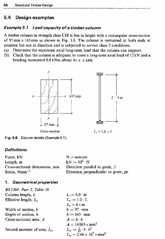
Structural Timber Design
xamples
A timber column in strength class C18 is 4m in height with a rectangular cross-section of 97mm x 145 mm as shown in Fig. 5.6. The column is restrained at both ends in position but not in direction and is subjected to service class 2 conditions. (a) Determine the maximum axial long-term load that the column can support. (b) Check that the column is adequate to resist a long-term axial load of 12 kN and a
bending momentof 0.8 kNm about its x-” axis.
Y !
Cross-section
Fig. 5.6 Column details (Example 5.1 ).
Force, kN Length, m Cross-sectional dimensions, mm Stress, Nmm-2
1 . ~ e o ~ e t r ~ ~ a ~ properties
133’5268 : Part 2, Table 18 Column length, L Effective length, L,
Width of section, b Depth of section, h Cross-sectional area, A
Second moment of area, I,,
L, = 1.0 x L
N :=newton
Direction parallel to grain, // Direction perpendicular to grain, pp
k~ := 103 . N
L := 4.0 m Le := 1.0 * L L e = 4 0 m b := 97-mm h := 145 + mm
A = 14065 omm2
I,, = 2.46 x l O7 o mm4
A . 1 ” b - h
I,, := L. b . h3 12
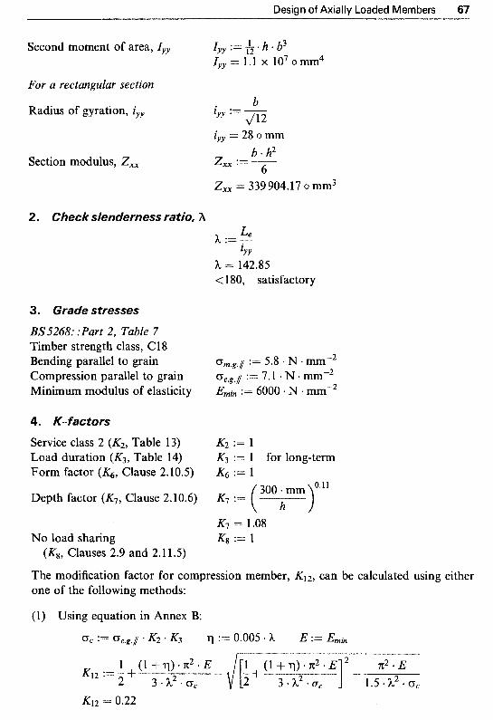
Design of Axially Loaded Members 67
Second moment of area, Iyy Iyy := h h * b3 lYy = 1.1 X io7 o m 4
For a rectangular section b
Radius of gyration, iyy ZYY := J12
Section modulus, Zxx
iyy = 28 o mm b * h2 zxx := -
Zxx = 339 904.17 o mm3 6
2. Check slenderness ratio, h G? h : = _ lYY
h = 142.85 < 180, satisfactory
3. Grade stresses
BS 5268: :Part 2, Table 7 Timber strength class, C18 Bending parallel to grain Compression parallel to grain ~ i n i m u m modulus of elasticity
4. K-factors
Service class 2 (K2, Table 13) Load duration (K3, Table 14) Form factor (K6, Clause 2.10.5)
Depth factor (IC7, Clause 2.10.6)
No load sharing (K8, Clauses 2.9 and 2.1 1.5)
:= 5.8 N e mm"2 oc.g.l := 7.1 N - mm-2 Emin := 6000 * N mm"2
K2 := 1 K3 := 1 for long-term K6 := 1
K7 := ( h ) 300 mm '*l1
The modification factor for compression member, K12, can be calculated using either one of the following methods:
(l) Using equation in Annex B:
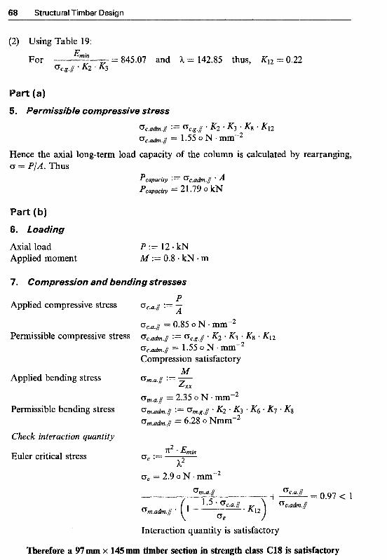
Structural Timber Design
(2) Using Table 19:
For Emin
%g.[ * K2 ' K3 = 845.07 and h = 142.85 thus, K12 = 0.22
0c.adm.l := 0c.g.l * K2 * K3 * K12 cTc.adm./ = 1.55 o N *mm-2
Hence the axial long-term load capacity of the column is calculated by rearranging, CT = P/A. Thus
Pcapacity := (Jc.ab.// * A Pcapacity 2 1.79 0 kN
Axial load P := 12 * kN Applied moment M := 0.8. kN m
o ~ ~ r e s s j o n and ~ e n d j n ~ stresses
P Applied compressive stress 0 c . a . i *- - '" A
0c.a.l = 0.85 o N - mm-2
0 C . a h . i == 1.55 o N .mm"2 Permissible compressive stress 0c.adm.i := K2 . K3 Kg K12
Compression satisfactory M Applied bending stress Gm.a.1 := -
&x
om.a, / = 2.35 o N * mm-2
cm.a&./ = 6.28 0 Nmm-2 ~ermissible bending stress 0m.adm.l := 0m.g. / / K2 * K3 * K6 * K7 *
Check interaction quantity
Euler critical stress n2 * E m h
h2 0, := -
0, = 2.9 o N
Interaction quantity is satisfactory
Therefore a 9'7 mm x 145 mm timber section in strength class C18 is satisfactory
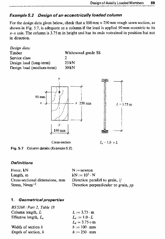
Design of Axially Loaded Members 69
For the design data given below, check that a 100mm x 250mm rough sawn section, as shown in Fig. 5.7, is adequate as a column if the load is applied 90mm eccentric to its P” axis. The column is 3.75 m in height and has its ends restrained in position but not in direction.
Design data: Timber Whitewood grade SS Service class 2 Design load (long-term) 25 kN Design load (medium-terrn) 30 kN
90
Y
Cross-section Fig. 5.7 Column details (Example 5.2).
~efjnjtjons
Force, kN Length, m Cross-sectional dimensions, mm Stress, Nmm“2
l . Geometrical properties
BS5268 : Part 2, Table 18 Column length, L Effective length, L,
Width of section b Depth of section, h
N := newton k~ := 103. N
L = 3.75 m
L, = 1.0 x L
Direction parallel to grain, // Direction perpendicular to grain, pp
L := 3.75 m L, := 1.0. L L, = 3.75 0 m b := 100 * mm h := 250 *

90 Structural Timber Design
Cross-sectional area, A A : = b . h
Second moment of area, I,, I,, := h * b * h3
Second moment of area, I,,,, Iyy := & * h b3
A = 25 000 o mm2
I,, = 1.3 X io8 0mm4
Iyy = 2.08 x lo7 o mm4 b For a rectangular section, radius
of gyration: i,,,, iyy := m iyy = 28.87 o mm
Section modulus, ZXx b 0 h2 zx, := -
Z,, = 1.04 x lo6 o mm3 6
2. Check slenderness ratio, A L e h := 7 lYY
h = 129.9 < 180, satisfactory
3. Grade stresses
BS5268 : Part 2, Tables 2 and 7 Strength classification Whitewood grade SS = C24 Bending parallel to grain := 7.5 N mm-2 Compression parallel to grain C T , . ~ . ~ := 7.9 - N mmm2 Minimum modulus of elasticity Emin := 7200 - N - mm"2
4. K-factors
Service class 2 (K2, Table 13) K2 := l Load duration (K3,Table 14) K3.lOng := 1 and K3.med := 1.25
Form factor (KG, Clause 2.10.5) K6 := 1
Depth factor (K7, Clause 2.10.6) K7 := ( h )
No load sharing K8 := 1
for long- and medium-terms
300 mm OJ'
K7 = 1.02
(K8, Clauses 2.9 & 2.11 -5)
Modification factor for compression member, .Kl2, can be calculated using either one of the following methods:

Design of Axially Loaded Members 71
(1) Using equation in Annex B:
(a) Long-term loading: U, := u,.~,,// * K2 * K3.lOng := 0.005 h E := Emin
1 ( l + q ) * ~ ~ * E x2 E K12.med := 5 + - -+ -
3 * h2 * U, 1.5 * h2 * U,
(2) Using Table 19:
(a) Long-term loading:
= 91 1.39 and h = 129.9 thus, K12.long = 0.27 0 c . g . i * K2 K3.long
(b) Medium-term loading: Emin
Dc.g.// ' K2 * K3.med = 729.11 and h = 129.9 thus, K12.med = 0.23
5. Loading
Eccentricity, e,, e,, := 90 mm (a) Long-term loading: Axial load Plong := 25 * kN Moment = axial load X eccentricity M1ong := P1ong e,,
(b) Medium-term loading: Axial load Pmed := 30 * kN Moment = axial load X eccentricity M m & := Pmed e,,
Mlong = 2.25 o kN * m
M m e d I== 2.7 o kN * m
6. ~o~press ion and ~ e n ~ i n g stress
(a) Long-term loading: K 3 := K3.lOng K12 := K12.long P :== PIong M := Mlong
P Applied compressive stress 0c .a . i := - A
u , , ~ . ~ = 1 o N mm-2
0 c . a h . i = 2.13 O N .mm-2 Compression satisfactory
Permissible compressive stress c~,,,h.i := u,~,J K2 + K 3 * Kg * K 1 2
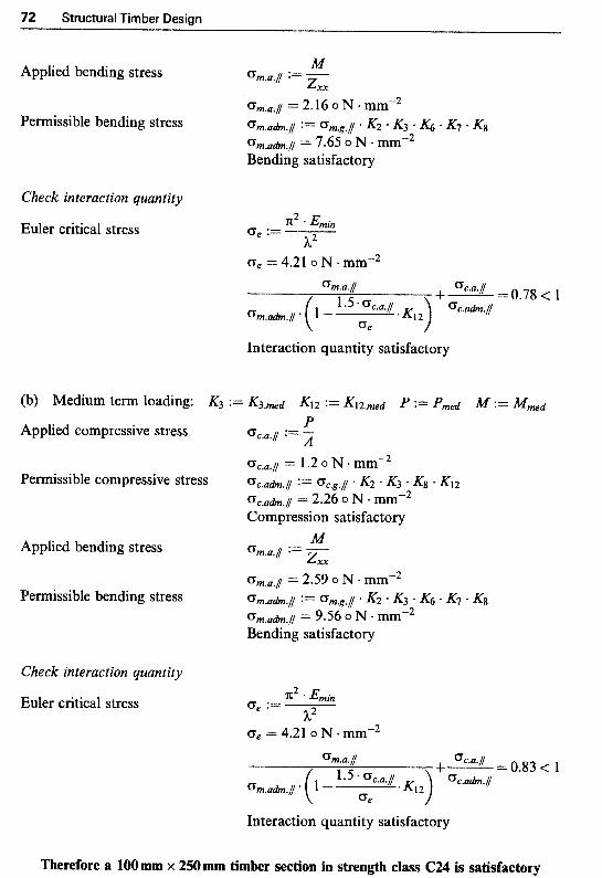
92 Structural Timber Design
Applied bending stress
Permissible bending stress
Check interaction quantity
Euler critical stress
(b) Medium term loading:
Applied compressive stress
Permissible compressive stress
Applied bending stress
Permissible bending stress
Check interaction quantity
Euler critical stress
Oe = 4.21 o N * mmm2
Interaction quantity satisfactory
0, = 4.21 o N. mmn2
Interaction quantity satisfactory
Therefore a 1OOmm x 250mm timber section in strength class C24 is satisfactory

Design of Axially Loaded Members 73
€xa~p/e 5.3 Design of a /Qad-bearing stud wa//
A stud wall, as shown in Fig. 5.8, has an overall height of 4.0m. the vertical studs are positioned at 600mm centres with noggings at mid-height. Carry out design calcula- tions to show that studs of 44 mm x 100 mm section in Cl 6 timber under service class l are suitable to sustain a long-duration load of 10.0 kN/m.
Y
12.5 mm
12.5 mm x -. 100.0 m
Plasterboards Y
Cross-section of a stud (44 m x 100 mm)
Fig. 5.8 Stud wall details (Example 5.3).
Definitions
Force, kN N :=newton Length, m k ~ : = 1 0 3 . ~ Cross-sectional dimensions, mm Direction parallel to grain, // Stress, Nmm"2 Direction perpendicular to grain, pp
1 . Geometrical properties
BS5268 : Part 2, Table 18 For each stud acting as a column, restrained about its y-y axis by plasterboards and restrained at both ends in position but not in direction:
Stud length, about x-x axis, L, L, := 4.0 m Effective length, about Le.x := 1 e0 L,
X-X axis, Le.z Le.x = 4 o m
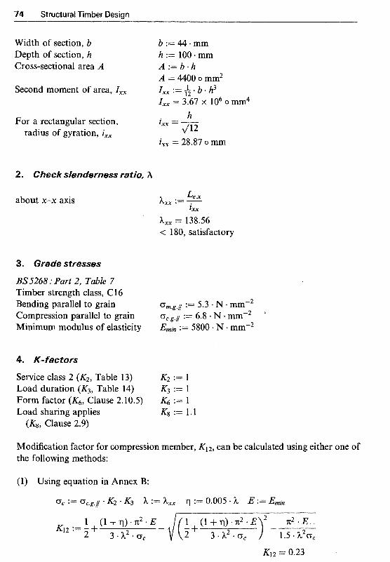
Structural Timber Design
Width of section, b b:=44*mm Depth of section, h h := 100. mm Cross-sectional area A A : = b * h
Second moment of area, Z,, Ixx := h * b * h3 A = 4400 o mm2
Z,, = 3.67 x lo6 o mm4 h For a rectangular section,
radius of gyration, ixx lXX = m ixx = 28.87 o mm
eck s~enderness ratio, h
about x-x axis
3. Grade stresses
35'5268 : Part 2, Table 7 Timber strength class, Cl 6 Bending parallel to grain Compression parallel to grain Minimum modulus of elasticity
4. ~ - f a ~ t o r s
Service class 2 (KZ, Table 13) Load duration (K3, Table 14) Form factor (K6, Clause 2.10.5) Load sharing applies (K8, Clause 2.9)
L., h,, := - 1,
h, = 138.56 < 180, satisfactory
Modification factor for compression member, K12, can be calculated using either one of the following methods:

Design of Axially Loaded Members 75
(2) Using Table 19: E m i n For = 852.94 and h = 138.56 thus, K12 = 0.23
oc.g./l K2 * K3
5. Loading
Uniformly distributed axial load Stud spacing, Sstud Axial load per stud
6. Compression stress
Applied compressive stress
Permissible compressive stress
Therefore 44mm x 100mm timber sections in strength class C16 are satisfactory
Example 5.4 Design of a load-bearing stud wall with lateral load
A stud wall forming part o f an open farm building, as shown in Fig. 5.9, has an overall height of 3.6m. The vertical studs are built-in to concrete at the base, support a roof
Roof framework
(a) Elevation Concrete foundation' (b) Side-elevation Fig. 5.9 Stud wall details (Example 5.4).
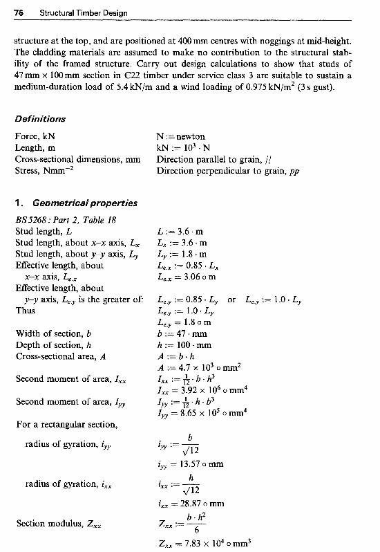
76 Structural Timber Design
structure at the top, and are positioned at 400mm centres with noggings at mid-height. The cladding materials are assumed to make no contribution to the structural stab- ility of the framed structure. Carry out design calculations to show that studs of 47 mm x 1OOmm section in C22 timber under service class 3 are suitable to sustain a medium-duration load of 5.4 kN/m and a wind loading of 0.975 kN/m2 (3 S gust).
e finitions
Force, kN Length, m Cross-sectional dimensions, mm Stress, Nmnr2
1 . ~ e o ~ e t r i c a i properties
BS5268 : Part 2, Table 18 Stud length, L Stud length, about x-x axis, L, Stud length, about y-y axis, Ly EflEective length, about
EEective length, about
Thus
x-x axis, Le, ,
y-y axis, Le.y is the greater of:
Width of section, b Depth of section, h Cross-sectional area, A
Second moment of area, I,,
Second moment of area, Iyy
For a rectangular section,
radius of gyration, iyy
radius of gyration, ixx
Section modulus, Z,,
N :=newton kN := lo3 * N Direction parallel to grain, // Direction perpendicular to grain, pp
L := 3.6 * m L, := 3.6 m Ly := 1.8 .m Le., := 0.85 * L, Le., = 3.06 o m
Le,y := 0.85 Ly or Le,y := 1.0 Ly Le.y := 1 .O * L y Le.y = 1.8 0 m b:=47*mm h := 100. mm
A := 4.7 x io3 o mm2
Z,, = 3.92 x lo6 o mm4
lyy = 8+65 x lo5 o mm4
A : = b * h
I,, := 1. b . h3 12
Iyy := G * h * b3
b ZYY := 1/12
:= 4 2
iyr = 13.57 o mm h
i,, = 28.87 o mm b h2 z,, := -
Z,, = 7.83 x lo4 o mm3 6

Design of Axially Loaded Members
about y-y axis
about x-x axis
BS5268 : Part 2, Table 7' Timber strength class, C22 Bending parallel to grain Compression parallel to grain Minimum modulus of elasticity
Service class 3 (K2, Table 13) Load duration (K3, Table 14)
Form factor (KG, Clause 2.10.5)
Depth factor (K7, Clause 2.10.6)
Load sharing applies (Kg, Clause 2.9)
Le.y hyy := - lYY
hyy = 132.67 Le. , h,, := -
h,, = 106 Both < 180, satisfactory hyy is the critical one
K7 := ( h ) 300 mm '*'I
Modification factor for compression member, K12
(l) ~edium-term loading (no wind): (a) Using equation in Annex B:
K 3 := K3.med DC := Gc.g.1 K2.comp ' K3 h := h y y ?l := 0.005 * h E := Emin K ~ . E
Kl2.med = 0.26 (b) Using Table 19:
E oc .g .1 * Kicornp * K 3
For = 924.44 and h = 132.67 thus, Kl2.med = 0.26
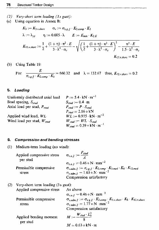
Structural Timber Design
(2) Very-short term loading (3s gust): (a) Using equation in Annex B:
K3 := K3.v.short o c := oc.g.// * K2.comp ' K3 h :"I= h y y II := 0.005 h E := Emin * K ~ . E
(b) Using Table 19:
5. foadjng
Uniformly distributed axial load P := 5.4 - kN m-1 Stud spacing, Sstud Sstud := 0.4 * Axial load per stud, Pstud pstud := p Sstud
Applied wind load, WL WL := 0.975 kN m-2 Wind load per stud, Y s t u d Wstud := WL Sstud
Pstud = 2.16 0 kN
W&d 0.39 0 kN m"
C o ~ ~ r e s s j o ~ and bending stresses
Medium-term loading (no wind): Pstud Applied compressive stress oc.a.1 := 7
per stud = 0.46 o N a mm-2
Permissible compressive Gc.a&.// := oc.g.// * K2.comp ' K3.med * K8 K12.med stress oc.ah,l = 1.63 o N -mmw2
Compression satisfactory
Very-short term loading (3 S gust): Applied compressive stress As above
Permissible compressive oca&.// := oc.g.// * K2.comp * K3.v.shor-t * K8 * Kl2.v.short
oc.u.~ = 0.46 o N . mm-2
stress Gc.udm.l = 1.77 0 N * Elm-2 Compression satisfactory
Wstud Applied bending moment M := per stud
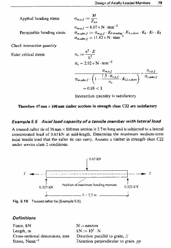
Design of Axially Loaded Members
Check i n t ~ ~ a c t i ~ n quantity
uler critical stress
0, = 2.92 o N a mm-2
0m.a.f
1.5 * Gc.a.1 %.ah.// * Kl2.v.short
= 0.98 < 1
Interaction quantity is satisfactory
ere~ore mber sections in s ~ e n ~ h class C22 are satis
le A trussed rafter tie of 38 mm x 100 mm section is 2.7 m long and is subjected to a lateral concentrated load of 0.65 kN at mid-length. Determine the maximum medium-term axial tensile load that the rafter tie can carry. Assume a timber in strength class C22 under service class 2 conditions.
l 0.65 lsN
T .-.-. T ~ _ _
/ t Position of maximum bending moment 0,325 kN 0.325 kN
? L L = 2 . 7 m 2 Fig. 5.1 0 Trussed rafter tie (Example 5.5).
Force, kN N :=newton Length, m kN := lo3 .N Cross-sectional dimensions, mm Direction parallel to grain, // Stress, Nmm-2 Direction perpendicular to grain, pp

80 Structural Timber Design
eo~etrical properties
BS5268 : Part 2, Table 18 Tie length, L EEective length, Le
Width of section, b Depth of section, h Cross-sectional area, A
For a rectangular section, radius of gyration, iyy
Section modulus, Zxx
L := 2.7. m L e := 1.O.L L e = 2.7 o m b := 38 *mm h := 100. mm
A = 3800 o mm2 b
A := b * h
ZYY := pj
iyy = 10.97 o mm b - h2
Zxx := -
Zxx = 63 333.33 o mm3 6
. ~ ~ e c ~ slenderness ratio, h L e h *- - iYY
h = 246.13
.-
< 250, satisfactory
3. Grade stresses
3S5268 : Part 2, Table 7 Timber strength class, C22 Bending parellel to grain := 6.8 N mmW2 Tension parallel to grain := 4.1 e N m mm-2 ~ i n i m u m modulus of elasticity Emin := 6500 + N mm-2
4. actors
Service class 2 (KZ, Table 13) K2 := 1 ~edium-term loading K3 := 1.25
Form factor (K6, Clause 2.10.5) .&j := 1
Depth factor (KT, Clause 2.10.6) K7 := ( h )
(K3, Table 14)
300 mm 0.1 1
K7 = 1.13
Width factor (K14, Clause 2.12.2) K14 := ( 3 0 0 ~ m m ~ ' 1 1
K14 = 1.13 No load sharing (K8, Clause 2.9) K8 := 1
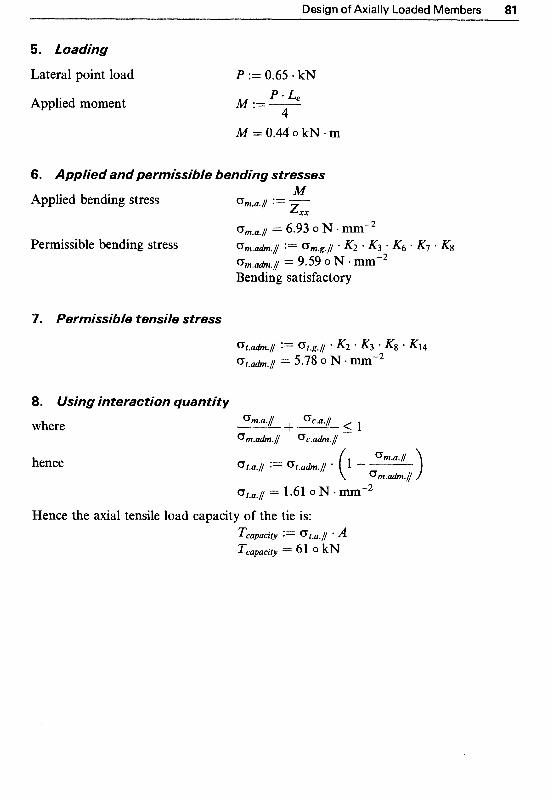
Design of Axially Loaded Members 81
5. ~ o ~ d i n g
Lateral point load P := 0.65 * kN P Le Applied moment M := -
4 M=0.44okN-m
6. fie^ a n d ~ e r ~ i s s j b ~ e bending stresses M
z x x Applied bending stress om.a.1 :=
Um.a.1 = 6.93 o N mm-2
o m . a h . 1 = 9.59 o N mmm2 Permissible bending stress o m a h . / := G m . g . 1 . K2 * K3 K6 KT -Kg
Bending satisfactory
7. ~ e r ~ i s s i ~ i e tensile stress
8. interactj~~ quantjty
where
hence
Hence the axial tensile load capacity of the tie is: Tcapacity := 0 t . a . l * A Tcapacity = 61 0 kN

Clued laminated timber, commonly known as gZuZarn, is a structural material obtained by gluing together at least four laminations of timber sections of usually 19-50 mm basic thickness so that the grain directions of all are parallel. Normally the laminations are dried to around 12-1 8% moisture content before being machined and assembled. This leads to a reduction in laminations’ thickness of around 3-5mm. Assembly is commonly carried out by applying carefully controlled adhesive mix to the faces of the laminations. They are then placed in mechanical or hydraulic jigs of the appropriate shape and size, and pressure is applied at right angles to the glue lines and is held until curing of the adhesive is complete. Clulam is then cut, shaped and any specified preservative and finishing treatments are applied. In Fig. 6.1 the cross-section of a typical glulam beam is shown.
Y Fig. 6.1 Cross-section of a glulam beam.
82
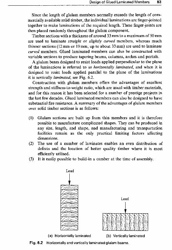
Design of Glued Laminated Members 83
Since the length of glulam members normally exceeds the length of com- mercially available solid timber, the individual laminations are finger-jointed together to make laminations of the required length. These finger-joints are then placed randomly throughout the glulam component.
Timber sections with a thickness of around 33 mm to a maximum of 50 mm are used to laminate straight or slightly curved members, whereas much thinner sections (l2 mm or 19 mm, up to about 33 mm) are used to laminate curved members. Glued laminated members can also be constructed with variable sections to produce tapering beams, columns, arches and portals.
A glulam beam designed to resist loads applied perpendicular to the plane of the laminations is referred to as hurizuntally laminated, and when it is designed to resist loads applied parallel to the plane of the laminations it is vertically laminated, see Fig. 6.2.
Construction with glulam members offers the advantages of excellent strength and stiffness-to-weight ratio, which are usual with timber materials, and for this reason it has been selected for a number of prestige projects in the last few decades. Glued laminated members can also be designed to have substantial fire resistance. A summary of the advantages of glulam members over solid timber sections is as follows:
Glulam sections are built up from thin members and it is therefore possible to manufacture complicated shapes. They can be produced in any size, length, and shape, and manufacturing and transportation facilities remain as the only practical limiting factors affecting dimensions. The use of a number of laminates enables an even distribution of defects and the location of better quality timber where it is most efficiently utilised. It is easily possible to build-in a camber at the time of assembly.
Load
Load
i
(a) Horizontally laminated (b) Vertically laminated
Fig. 6.2 Horizontally and vertically laminated glulam beams.
4 Structural Timber Design
This chapter details the general considerations necessary for the design of flexural and axially loaded glued laminated members.
The main design considerations for flexural and axially loaded glulam members are the same as those described in detail in Chapters 4 and 5 respectively. It is therefore assumed that the reader is familiar with the various modification factors and all other aspects of the design methodology detailed in these previous chapters. They are not repeated at length here, but when a factor is used, reference is made to the explanatory item of the relevant chapter.
BS 5268 : Part 2 : 1996, Section 3 deals with the design. of glued laminated timber and specifies that such timber should be manufactured in accordance with Clause 3.4 of the code and also with the recommendations of BS EN 386 : 1995 Glued laminated timber. Performance requirements and mini~um ~roduction requirements. It also requires that all timber used for laminated softwood members (similar to solid section timber, see Chapter 2, Section 2.1) should be strength graded visually or mechanically in accordance with
S EN 5 18 or BS EN 5 19, respectively. Glulam strength properties may be determined from the strength class
properties given in Table 7 of the code (reproduced here as Table 2.3). These are described in detail in the following sections.
If a glulam section is manufactured using the same grade throughout it is referred to as single-grade glued laminated member. The grade stresses given in Tables 7-12 of BS 5268 : Part 2 apply primarily to solid structural timber. In order to determine the grade stresses for a horizontally glued laminated softwood or hardwood member, Clause 3.2 of the code recommends that the strength class stresses given in its Tables 7-12 for the relevant grade and species are multiplied by the modification factors K15 to K20 according to the nature of stress and the number of laminations. The modification factors $ l l5 to K20, detailed in Table 21 of the code, are for single-grade horizontally glued laminated members (Table 21 is reproduced here as Table 6.1).
For economic reasons there are many instances where members may be horizontally laminated with two different strength class timber sections.

Design of Glued Laminated Members 85
Table 6.1 Modification factors Kls, K17, .Kl8, K19 and K20 for single-grade glued laminated members and horizontally glued laminated beams (Table 21, BS 5268)
Strength Number of Bending // Tension // Compression Compression Shear // Modulus of classes laminationsa to grain to grain //to grain L to grainb to grain elasticityc
(om,g,/) (ot,g,/) (oc,g,/) (oc,g,.d (zg,/) Emem K1 5 K1 6 K1 7 K1 8 K19 K20
C27, C30, 4 or more D50, D60, D70
C22, C24, 4 D35, D40 5
7 10 15
20 or more
C16, C18, 4 D30 5
7 10 15
20 or more
1.39
1.26 1.34 1.39 1.43 1.48 1.52
l .05 1.16 1.29 1.39 1.49 1.57
1.39 1 . 1 1 1.49 1.49 1.03
1.26 1.04 1.55 2.34 1.07 1.34 1.39 l .43 1.48 1.52
1.05 1.07 1.69 2.73 1.17 1.16 1.29 1.39 1.49 l S 7
aInterpolation is permitted for intermediate numbers of laminations
‘KZ0 should be applied to the mean value of modulus of elasticity K18 should be applied to the lower value given in Table 7 for compression perpendicular to grain
Higher-grade laminations are normally placed in the outer portions of the member where they are effectively used, and lower-grade laminations are placed in the inner portion (core) where the lower strength will not greatly affect the overall strength. The combination is permitted provided that the strength classes are not more than three classes apart (as given in Table 7 of the code.) For example C24 and C16 can be horizontally laminated but C24 and C14 should not. The code also requires that in horizontally laminated members where combination grades are used, they should be fabricated so that not less than 25% of the depth at both the top and bottom of the member is of the higher strength class, see Fig. 6.3. For such members the grade stresses should be taken as the product of the strength class stresses (given in Table 7 ) for the higher strength class laminations and the modification factors from Table 21 of the code. In addition, for bending, tension and compression parallel to grain, the grade stresses should be multiplied by 0.95.

Structural Timber Design
one-grade
Higher-grade
Lower-grade
4 Higher-grade
(a) Single-grade (b) Combined-grade
Fig. 6.3 Horizontally glued laminated members.
6.3.3 Permissible stresses for horizontally glued laminated members
The per~issible stresses for a horizontally glued laminated member are determined as the product of grade stresses, given in Table 7, by any relevant modification factors, i.e. K2, K3,. . . , KI4 and modification factors K15 to K20 appropriate to the number of laminations. These are summarised below:
Bending parallel to grain: for a single-grade glulam, Om,ah , / / = Om,g,// X K ~ I Y ~ K ~ K ~ K ~ K I ~ for a combined-grade glulam, O m , a h , / / = Om,g,// X K~K~&&K&~s x 0.95
Tension parallel to grain: for a single-grade glulam, G t , a h , f/ = O,,g,// x K2K3-&K14K16 for a combined-grade glulam, O t , a h , i = ctts,/ X K&3&K14K16 x 0.95
Compression parallel to grain: for a single-grade glulam, oc,adm,// = Oc,g,// x K2K3K8K12K17 for a combined-grade glulam, Oc,adm,// = X &K&K12K17 X 0.95
Compression perpendicular to grain: for both single- and combined-grade glulam members,
Oc ,ah , l . = oc,g,l. X K2K3K4K8K18 Shear parallel to grain:
for both single- and combined-grade glulam members,
z a h , / / = zg,// x K2K3K5K8K19 Modulus of elasticity:
for both single- and combined-grade glulam members,

Design of Glued Laminated Members
It should also be noted that for tension perpendicular to grain and torsional shear, permissible stresses should be calculated in accordance with Clause 2.7 of the code, and factors K19 and K27 should be disregarded. For example,
For tension perpendicular to grain: for both single- and combined-grade glulam members,
In determining the permissible stresses for glued laminated members, the modification factors used (if relevant) are:
K1 4
service class 3 (wet exposure condition), see Section 2.5.2, duration of loading, see Section 2.5.4, bearing stress, see Section 4.5.1, shear at notched end, see Section 4.6.1, form factor, see Section 4.3.2, depth factor, see Section 4.3.3, which applies to the full glulam section size, not the individual laminates, load sharing system, see Section 2.5.6, factor for compression member, see Section 5.2.3 (for calculation of K12 for glulam compression members, the value of Egiulam, as defined, should be used, i.e. Egiulam = Ernean x K20), width factor for tension member, see Section 5.3.2, which applies to the full glulam section size, not the individual laminates, are the appropriate grade stress modification factors for single- grade horizontally laminated members. For combined-grade mem- bers, these factors apply to the higher-grade lamination stresses.
Attention is drawn to the definitions for K7, K12 and K14 given above.
ically glued lami
A glulam beam designed to resist loads applied parallel to the plane of laminations is referred to as a vertically l a m i ~ a t e ~ beam. This is illustrated in Fig. 6.2. BS 5268 : Part 2, Clause 3.3 specifies that permissible stresses for vertically
glued laminated beams are governed by the particular conditions of service and loading defined in its Clauses 2.6.2, 2.8 and 2.9 which relate to service class 3 (wet-exposure) condition, duration of loading and load-sharing systems respectively; and also by the additional modification factors Kz7, K28 and K29 given in Table 22 of the code appropriate to the number of laminations. Table 22 of the code is reproduced here as Table 6.2.
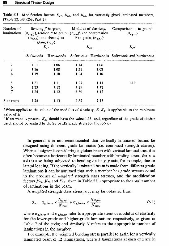
8 Structural Timber Design
Table 6.2 Modification factors K27, and K29, for vertically glued laminated members, (Table 22, BS 5268 :Part 2)
Number of Bending // to grain, Modulus of elasticity, Compresison l. to grainb laminations ( G ~ ~ , / ) , tension // to grain, and compression & g , d
@&g,/), and shear I/ to /I to grain, (Gc;g;/)
grain, &,l) K27 K28 K29
Softwoods Hardwoods Softwoods Hardwoods Softwoods and hardwoods
2 1*11 1.06 1.14 1.06 3 1.16 1 .os l .21 l .os 4 1.19 1.10 1.24 1.10
5 1.21 1.11 1.27 1.11 6 1.23 1.12 1.29 1.12 7 1.24 1.12 1.30 1.12
8 or more 1.25 1.13 1.32 1.13
1.10
aWhen applied to the value of the modulus of elasticity, E, K28 is applicable to the minimum value of E bIf no wane is present, K29 should have the value 1.33, and, regardless of the grade of timber used, should be applied to the SS or HS grade stress for the species
In general it is not recommended that vertically laminated beams be designed using different grade laminates (i.e. combined strength classes). When a designer is considering a glulam beam with vertical laminations, it is often because a horizontally laminated member with bending about the x-x axis is also being subjected to bending on its y” axis, for example, due to lateral loading. If the vertically laminated beam is made from different grade laminations it can be assumed that such a member has grade stresses equal to the product of weighted strength class stresses, and the modification factors K27, K28 and K29, given in Table 22, appropriate to the total number of laminations in the beam.
A weighted strength class stress, G,, may be obtained from:
where CTg,lower and Gg,higher refer to appropriate Stress or modulus of elasticity for the lower-grade and higher-grade laminations respectively, as given in Table 7 of the code; and similarly N refers to the appropriate number of laminations in the member.
For example, the weighted bending stress parallel to grain for a vertically laminated beam of 12 laminations, where 3 laminations at each end are in

Design of Glued Laminated Members 89
C24 and 6 inner ones are in C18 softwood timber, may be calculated as follows: From Table 7 of the code (Table 2.3 in this book):
for Cl 8 timber, om,g , / = 5.8 N/mm2 for C24 timber, om,g , / = 7.5 N/mm2
Therefore the weighted grade bending stress is:
Gw,m,g,/ = 5.8 X 6 + 7.5 X 6 = 6.65 N/mm2
Hence the weighted bending stress parallel to grain for this glulam beam is calculated as: From Table 22 of the code (Table 6.2 in this book), for 12 laminations, K27 = 1.25.
ow,m, / = 6.65 X 1.25 = 8.31 N/mm2
The permissible stresses for a vertically glued laminated member are determined as the product of grade stresses (or weighted grade stresses in the case of a member with combined-grade laminations) by any relevant modi- fication factors, i.e. KZ, &, . . . , K14 and modification factors K27, K2g and KZ9 appropriate to the number of laminations). These are summarised below:
Bending parallel to grain: om,,&,/ om,g , / x K2K3K6K7KgK27 Tension parallel to grain: ot,udm,/ = o t , g , / x K2K3KgK~4K27 Shear parallel to grain: “a&,/ = “g,/ x K2K3K5Kg~27 Compression parallel to grain: ot,adm,/ = Ot,g,/ x K2~3KgK~2~28 Compression perpendicular to grain: o,,,h,~- = oClg,J- x K2K3&K8 K29 Modulus of elasticity: Eg1ulum ==I Emeun
For vertically laminated beams, the E value (for 4 or more laminations) is Erne,, and is only applicable to Ernin. It should be noted that the size factors K7 and K14 for all glulam members, whether horizontally or vertically laminated, should be applied to glulam strengths not to the individual larni- nate strengths.
It should also be noted that for tension perpendicular to grain and torsional shear, permissible stresses should be calculated in accordance with Clause 2.7 of the code, and factor K27 should be disregarded.
Lateral torsional buckling is unlikely to be a problem as the depth-to- breadth ratio related to bending about the y-y axis will almost certainly be less than 1.0 and any beam tends to buckle only at right angles to the direction of bending.

Structural Timber Design
BS 5268 : Part 2 : 1996, Clause 3.5 recommends that in addition to the deflection due to bending, the shear deflection may be significant and should be taken into account. Attention is drawn to deflection criteria for flexural members which were covered in detail in Section 4.4, as the same criteria apply to glulam beams.
As it is easily possible to build-in a camber at the time of assembly, the code specifies that members can be pre-cambered to offset the deflection under dead or permanent loads. In such cases the deflection under live or intermittent imposed load should not exceed 0.003 of the span.
ed glued lami~ate~ beams
Glued laminated beams are often curved and/or tapered in order to meet architectural requirements, to provide pitched roofs, to obtain maximum interior clearance and/or to reduce wall height requirements at the end supports. The most commonly used types are the curved beams with constant rectangular cross-section and the double tapered beams (see Fig. 6.4).
The distribution of bending stress, urn, in a curved beam is non-linear and, in addition, radial stresses, er, perpendicular to the grain are caused by bending moments. If the bending moment tends to increase the radius of curvature, the radial stresses are in tension perpendicular to the grain (i.e. 0, = at,L); and if it tends to decrease the radius of curvature, the radial stresses are in compression perpendicular to the grain (i.e. Gr = u c , ~ ) .
Curved glulam beams are formed by bending laminations in purpose- built jigs during the production process. In order to make allowance for the initial stresses induced in the laminations, a modification factor .K33 has
(a) Curved beam
(b) Double tapered beam
Fig. 6.4 Curved and double tapered beams.

Design of Glued Laminated Members
been introduced. For curved glulam beams with constant cross-section, BS 5268 : Part 2, Clause 3.5.3 specifies the following requirements:
(l) The ratio of the radius of curvature, r, to the lamination thickness, t , should be greater than the mean modulus of elasticity, in N/mm2, for the strength class divided by 70, for both softwoods and hardwoods (see Fig. 6.5). Therefore check that:
r &lean ->- t 70
r (2) If - < 240, then the bending, tension and compression grade stresses t
parallel to grain should be multiplied by the modification factor where
K33 = 0.75 + 0.001 and K33 5 1.0 t
/ /
Point of tangency
Cross-section A-A
\
Bending stress, CT, Radial stress, G,
Fig. 6.5 Curved glued laminated beam with stress distributions at apex.

Structural Timber Design
(3) In curved beams, where the ratio of the minimum mean radius of curvature, rmean, to the depth, h, is less than or equal to 15 (i.e. if
5 15), then the bending stress induced by a mmnentp M , should rmean h
be calculated as:
(a) Bending stress in the extreme fibre on the concave face, 6M bh2 o m = k34 -
where:
K34 = 1 + ( 0.5 - rmtan) for y 5 10, and
K34 = 1.15 - (1.01 y ) for 10 < - 5 15 rmean h
(b) Bending stress in the extreme fibre on the convex face, 6M bh2
O m =-
(4) The radial stress, or, induced by a bending moment, M, should be calculated as:
where:
If the moment tends to increase the radius of curvature of the beam, the radial stress will be tension perpendicular to the grain and the value of or should not be greater than the value derived in accordance with Clauses 3.2 and 2.7 of the code. Therefore:
or 5 ot,adm,l_ = +.g,// x K2K3K8 (6.5)
where, from Section 2.5.7, C T ~ , ~ , ~ = $ T ~ , , / . If the moment tends to reduce the radius of curvature of the beam, the radial stress will be compression perpendicular to the grain and the value of Or should not be greater than 1.33 times the compression perpendicular to the grain stress for the strength class. Therefore:
or 5 1.33 X o,,ah,L = 1.33 X c ~ , , g , l X K2K3~KaKla (6.6)
Baird and Qzelton (1984) Timber Designer’s ~ a n u a l , 2nd ed. Blackwell Science,
Mettem, C.J. (1986) Structural Timber Design and Technology. Longman Scientific Oxford.
and Technical, Harlow.

Design of Glued Laminated Members
TRADA (1995) Glued laminated timber - an introduction, Wood Information, Section 1, Sheet 6. Timber Research and Development Association, High Wycombe, UK.
A series of glulam beams of l15 mm wide x 560 mm deep (14 laminations) with an effective span of 10.5 m is to be used in the construction of the roof of an exhibition hall. The roof comprises exterior tongued and grooved solid softwood decking exposed on the underside and covered on the top with 3 layer felt and chippings. For the design data given below, (a) check the suitability of the section, (b) determine the camber required.
Design data Timber Imported whitewood in strength class C24 and
service class 1 Bearing width 9Omm each end Dead load (long-term): Exterior decking 0.75 kN/m 3 layer felt and chippings 0.63 kN/m Beam self-weight 0.3 kN/m Imposed load (medium-tem) 2.5 kN/m
.-
i
Y Fig. 6.6 Cross-section of glulam beam (Example 6.1).
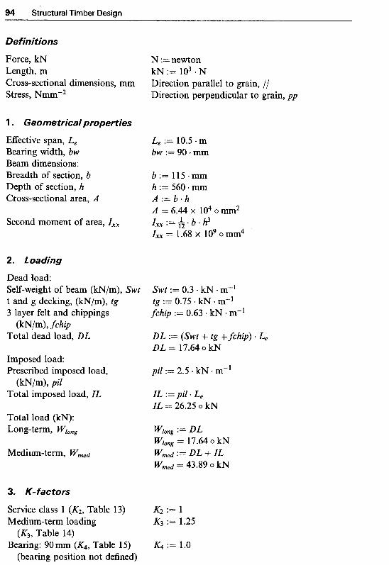
94 Structural Timber Design
~e finjtions
Force, kN Length, m Cross-sectional dimensions, mm Stress, Nrnmw2
1 . Geometrical properties
Effective span, L, Bearing width, bw Beam dimensions: Breadth of section, b Depth of section, h Cross-sectional area, A
Second moment of area, Zxx
2. ~ o a ~ j n ~
Dead load: Self-weight of beam (kN/m), Swt t and g decking, (kN/m), tg 3 layer felt and chippings
Total dead load, DL
Imposed load: Prescribed imposed load,
Total imposed load, IL
Total load (kN): Long-term, Wlong
Medium-term, Wmed
(kN/m), fchip
(kN/m), Pil
3. K-factors
Service class 1 (KZ, Table 13) Medium-term loading
Bearing: 90 mm (K4, Table 15) (K3, Table 14)
(bearing position not defined)
N := newton kN := lo3 * N Direction parallel to grain, ,// Direction perpendicular to grain, pp
Le := 10.5 m bw := 90.mm
b := 115.- h := 560. mm
A = 6.44 X lO4omm2
Zxx = 1.68 x lo9 o mm4
A : = b * h
: = L . b . h 3 12
Swt := 0.3 kN m-] tg := 0.75 kN m-] fchip := 0.63 lcN. m-1
DL := (Swt + tg + fihip) * Le DL = 17.64 o kN
pil := 2.5 kN - m"'
ZL := pi1 a L, IL = 26.25 o kN
WJong := DL Wlong = 1'7.64 o kN w m e d := DL + ZL w m e d = 43.89 0 kN
K2 := l K3 := 1.25
K4 := 1.0

Design of Glued Laminated Members 95
Notched end effect K5 := l
Form factor (K6, Clause 2.10.5) K6 := 1 Depth factor (K7, Clause 2.10.6)
to provide a dimensionless value for K7 in Mathcad, let: h1 := h mm"
(K5, Clause 2.10.4)
for h > 300mm h; + 92 300 h; + 56 800
K7 0.81 *
K7 = 0.89 NO load sharing (Kg, clause 2.9) := 1
Glulam m o d ~ c a t ~ o n factors (Table 21): Single-grade, 15 laminates in
Bending // to grain, K15 Compression perpendicular
Shear // to grain, K19 Modulus of elasticity, K20
C24 timber
to grain, K18
4. Grade stresses
BS5268 : Part 2, Table 7 Timber strength class, C24 Bending // to grain Compression perpendicular
Shear // to grain Mean modulus of elasticity
to grain
5. ~ e ~ d j ~ g stress
Applied bending moment
Section modulus
Applied bending stress
Permissible bending stress
Gm,g.// := 7.5 N mm-2 cF,.g.pp := 1.9 N mm-2
:= 0.71 N . mm-2 Emean := 10 800 N mmm2
Mmed = 57.61 o kN * b * h2 zxx := -
Zxx = 6.01 X lo6 o mm3 6

96 Structural Timber Design
. ~ateraJ st~bi~ity
Clause 2.10.8 and Table 16
Maximum depth-to-breadth ratio, h/b
7. Shear stress
Applied shear force
Applied shear stress
Permissible shear stress
8. Bearing stress
Applied load
Applied bearing stress, (bearing area = b bw)
Permissible bearing stress
9. Deflection
Modulus of elasticity of glulam, E
Deflection due to bending
Deflection due to shear
Total deflection
h - = 4.87 b Ends should be held in position and compression
edges held in line by direct connection of t & g decking to the beams
w m e d Fv := 7
A m = 34.02 o mm
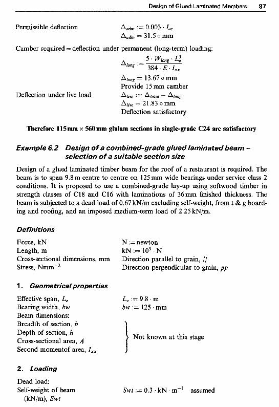
Design of Glued Laminated Members 97
Permissible deflection Aah := 0.003 * Le Aah = 31.5 omm
Camber required = deflection under permanent (long-term) loading:
Along = 13.67 o mm Provide 15 mm camber
Deflection under live load Alive := A t o t a l - Along Alive 21.83 o mm Deflection satisfactory
Therefore 115 mm x 560 mm glulam sections in single-grade C24 are satisfactory
€xample 6.2 Design of a combined-grade glued laminated beam - selection of a suitable section size
Design of a glued laminated timber beam for the roof of a restaurant is required. The beam is to span 9.8 m centre to centre on 125 mm wide bearings under service class 2 conditions. It is proposed to use a combined-grade lay-up using softwood timber in strength classes of C18 and C16 with laminations of 36 mm finished thickness. The beam is subjected to a dead load of 0.67 kN/m excluding self-weight, from t & g board- ing and roofing, and an imposed medium-term load of 2.25 kN/m.
Definitions
Force, kN Length, m Cross-sectional dimensions, mm Stress, Nmmm2
1 . Geometrica/properties
Eflt'ective span, L, Bearing width, bw Beam dimensions: Breadth of section, b Depth of section, h Cross-sectional area, A Second momentof area, I,,
2. Loading
Dead load: Self-weight of beam
(kN/m), Swt
N :=newton kN := lo3 * N Direction parallel to grain, // Direction perpendicular to grain, pp
Le := 9.8 m bw := 125. mm
Swt := 0.3 - kN . m" assumed

Structural Timber Design
Prescribed dead load
Total dead load, DL
Imposed load: Prescribed imposed load
Total imposed load, IL
(kN/m), PDL
(kN/m), Pi1
Total load ( k N ) : Long-term,
Medium-term, Wmed
3. K-factors
Service class 2 (K2, Table 13) Medium-term loading
(K3, Table 14) Bearing: 125 mm (K4, Table 15)
(bearing position not defined) Notched end effect
(K5, Clause 2.10.4) Form factor (K6, Clause 2.10.5) Depth factor (KT, Clause 2.10.6)
No load sharing (Kg, Clause 2.9)
Glularn ~ o d ~ c a t i o n factors (Table BS5268 : Part 2, Clause 3.2 Table 7, for C18 timber
Bending // to grain, K15 Compression perpendicular
Shear // to grain, K19 Modulus o f elasticity, K20
4. Grade stresses
BS5268 : Part 2, Table 7 Timber strength class, C18 Bending // to grain Compression perpendicular
to grain, &g
to grain
PDL := 0.67 kN + m-'
DL := (Swt + PDL) Le DL = 9.51 o kN
pi1 := 2.25 + kN m"
IL := pi1 * Le IL = 22.05 o kN
L
K2 := 1 K3 := 1.25
K4 := 1.0
K5 := 1
K6 := 1 Since section size is not known, at this stage
assume, K7 := 1 Kg := 1
?l) : Stress values for the higher-grade timber apply Since number o f laminations is not known,
ignore at this stage
K20 := 1.17

Design of Glued Laminated Members 99
Shear // grain zg.i := 0.67 N mm-2 Mean modulus of elasticity Ernean := 9100 * N * mm-2
Selecting a trial section
Using deflection criteria: Modulus of elasticity for E := Emean - K20
glulam, E E = 1.06 x lo4 o N. mmF2 Permissible deformation &h := 0.003 0 L,
under imposed load = 29.4 o mm 5 * I;.t."ed * L2 384 *E. &h
Required second moment of Zxx,rqd := area, Zxx using &h under imposed load Zxx.rqd = 1.24 X io9 o mm4
Using lateral stability criteria: In order to achieve lateral stability by direct fixing of decking to beams, the depth- to-breadth ratio should be limited to 5, i.e. h < 5b. Substituting for h = 5b in zxx = bh3/i2 and equating it to zxx,rqd:
12 * zxx.rqd 114
Zxx.rgd = * ' b)3 will give b := ( 53 ) 12 b = 104.36 o mm
h = 521.79 o mm and depth of section, h h : = 5 * b
Try a 110 mm x 540mm deep section with 15 laminations of 36 mm in thickness
Trial beam dimensions: Depth (mm), h h := 540. mm Breadth (mm), b b : = 11O.mm Modification factor K7 for
section depth: to provide a dimensionless value for K7 in Mathcad, let: h1 := h mm"
for h > 300mm h: + 92 300 K7 := 0.81 * h: + 56 800
K7 = 0.89
Glulam modtjication factors (Table 21): BS5268 : Part 2, Clause 3.2 Stress values for the higher-graded Combined-grade, 8 laminates in
Cl8 timber, by interpolation Bending // to grain, K15 K15 :== 1.32 Compression perpendicular to K18 := 1.69
Shear // to grain, K19 K19 := 2.73 Modulus of elasticity, K20 := 1.17
grain, KI8
timber apply

1 Stru~tural Timber Design
Applied bending moment
Section modulus
Applied bending stress
Permissible bending stress
Check self-weight: BS5268 : Part 2, Table 7 Density Beam self-weight (kN/m): Actual
Assumed
7. ~ateral sta~iljty
Clause 2.10.8 and Table 16
Maximum depth-to-breadth ratio, hlb
8. Shear stress
Applied shear force
Applied shear stress
Permissible shear stress
h b - = 4.91
Ends should be held in position and compression edges held in line by direct connection of t & g decking to beams
w m e d F,, := - 2 F,, = 15.78 o kN

Design of Glued Laminated Members 101
Applied load w m e d F:=-" 2
F = 15.78 o kN
Applied bearing stress 0c.a.pp := (bearing area = b bw) (3%) 0c.a.pp = 1.15 o N mm"2
0 c . a h . p p = 4.65 o N.mm-2 Bearing stress satisfactory
Permissible bearing stress 0c.adm.pp := 0c.g.pp * K2 K3 K8 K18
Modulus of elasticity for glulam, E
Second moment of area
Deflection due to bending
Deflection due to shear
E := Emean K20 E = 1.06 x lo4 o N - mm-2
b h3 12 rxx := -
zXx = I .U x io9 o mm4
A,,, = 25.16 0 mm 19 S2 ' A, := (b * h) * E
A, = 1.17 o mm
1 Cl8 timber
I Cl6 timber
C18 timber I
Fig. 6.7 Cross-section of glulam beam (Example 6.2).

4 02 Structural Timber Design
Total deflection
Permissible deflection
Atotal := A m +. As Atotal = 26.34 o mm A a h := 0.003 * L, A a h = 29.4 o mm Deflection satisfactory and no pre-cambering
is required
Therefore adopt a 110 mm x 540 mm glulam section in combined-grades of C18 and C16
€xamp/e 6.3 Design of a f/ooring system
Design of a flooring system using glued laminated timber beams for the first floor of an art gallery is required. The flooring arrangement comprises main beams with effective span of 9.6 m at 4.5 m centres supporting secondary beams at 0.8 m centres and 38 mm tongued and grooved (t & g) flooring using hardwood timber. The secondary beams are simply supported on 100mm hangers attached to main beams which are in turn sup- ported on load-bearing walls providing a 1'75 mm bearing width at each end.
It is proposed to use softwood timber in strength class of C24 with laminations of 38 mm finished thickness, single-grade and horizontally glued laminated throughout. The floor is subjected to a dead load of 0.4'7 kN/m2, excluding self-weight, and an imposed medium-tern load of 3.25 kN/m2.
Definitions
Force, kN N :=newton Length, m kN := lo3 - N Cross-sectional dimensions, mm Direction parallel to grain, // Stress, Nmm"2 Direction perpendicular to grain, pp
A. Design of tongued and grooved boarding
Assuming t & g boarding comprises 100 mm wide timber beams of thickness (depth) 38 mm simply supported on joists.
'1. Loading
Secondary beam spacing, Js Js := 0.8 m t & g width, b b := 100. mm t & g thickness, t t := 38. mm Dead load: BS5.268 : Part 2, Table 7 Average density, D30 hardwood pmean := 640 v kg * m"3 t & g boarding, self-weight tg := pman g t
(Wm2), tg tg = 0.24 o kN m-2

?--"-- 4.5 m 1 4.5 m 1 4.5 m F ! ! ! ! l I , I I
-. . .- ! ~!
! ! ! !
! ! - _ _ e _ ...
b
-.
-. .-
Secondary beams Main beams ' (a) Support structure layout
v-4 v-4
300 m t & g hardwood
(b) Section A-A: secondary beam details
300 mm I
4 9.60 m I
(c) Main beam details Section C-C
Fig. 6.8 Details of flooring system (Example 6.3).

104 Structural Timber Design
Prescribed dead load PDL := 0.47 kN - m-2
Total dead load (kW, DL DL := PDL + tg DL = 0.71 o kN m-2
Imposed load (kN/m2), IL IL := 3.25 kN . me2 Total load (kN), W W:=(DL+IL)*b*Js
(kN/m2), PDL
W = 0.32 o kN
2. K- factors
Service class 1 (K2, Table 13) K2 := 1 Medium-term loading K3 := 1.25
Bearing (G, Clause 2.10.2) K4 := 1 .O assumed Notched end effect K5 := 1
Form factor (KG, Clause 2.10.5) K6 := 1 Depth factor (K?, Clause 2.10.6) K7 := 1.17
Load sharing applies Kg := 1 . 1
(K3, Table 14)
(K5, Clause 2.10.4)
for h 5 72mm
(K8, Clause 2.9)
3. Grade stresses
&S135268 : Part 2, Table 7 Strength classification Strength class D30 Bending /I to grain C T , . ~ , / / := 9.0 N * Mean modulus of elasticity Emean := 9500 N + mme2
4. Bending stress
Applied bending moment M:=----” W * JS
8 M = 0.03 o kN m
C T , . , ~ . , J = 14.48 o N mm-2 Permissible bending stress om.adm./l := om.g.1 K2 K3 K6 * K7 ’ K8
Since Z = - * t2, therefore 6 trqd = 1 1.46 0 mm Thickness satisfactory
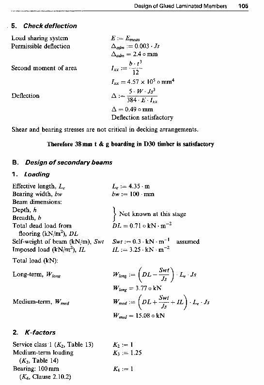
Design of Glued Laminated Members 105
Load sharing system Permissible deflection
Second moment of area
Deflection
E := Ehean A a h := 0.003 * JS A a h = 2.4 o mm
b . t 3 zxx := - 12 zXx = 4.57 x io5 o mm4
A :=
A = 0.49 o mm Deflection satisfactory
5. W * Js3 384 * E * Zxx
Shear and bearing stresses are not critical in decking arrangements.
Therefore 38 mm t & g boarding in D30 timber is satisfactory
B. Design of secondary beams
1 . Loading
EfTective length, L, Bearing width, bw Beam dimensions: Depth, h Breadth, b Total dead load from
flooring (kN/m2), DL Self-weight of beam (kN/m), Swt Imposed load (kN/m2), ZL Total load (kN):
Long-term, ?VIong
Mediumterm, Wmed
2. K- factors
Service class 1 (K2, Table 13) Medium-term loading (K3, Table 14)
Bearing: l00 mm (Ka, Clause 2.10.2)
Le := 4.35 * m bw := 100 - mm
Not known at this stage
DL = 0.71 o kN m-2
Swt := 0.3 kN m-' assumed ZL := 3.25 kN mW2
K2 := 1 K3 := 1.25
K4 := 1

1 Structural Timber Design
Notched end effect K5 := 1
Form factor (&, Clause 2.10.5) K6 := 1 Depth factor (KT, Clause 2.10.6) K7 := 1 assumed No load sharing (Ks, Clause 2.9) Kg := 1
(K5, Clause 2.10.4)
Glulam ~ o d ~ c a t i o n factors (Table 21): BS5268 : Part 2, Clause 3.2 Bending I / to grain, K15 Compression perpendicular Since number of laminations is not known,
Shear // to grain, K19 Modulus of elasticity, K2@ K20 := 1.07
i to grain, KIs ignore at this stage
3. Grade stresses
13s 5268 : Part 2, Clause 3.2 Table 7, for C24 timber Bending // to grain Compression perpendicular
Shear // to grain Mean modulus of elasticity
to grain := 0.71 N mm"2
Em,,, := 10 800 * N mm"2
Selecting a trial section
Using deflection criteria: Modulus of elasticity for E := Ernean K20
Permissible deformation &h := 0.003 * L e glulam, E E = 1.16 X 1 0 ~ 0 ~ . m m - ~
A,* = 13.05 o mm
Using lateral stability criteria: In order to achieve lateral stability by direct fixing of decking to beams, the depth- to-breadth ratio should be limited to 5, i.e. h < 5b. Substituting for h = 5b in Ixx = bh3/i2 and equating it to Ixx.rgd:
12 * Ixx.rqd 1 /4
Ixx.rqd = * (5 * b)3 will give b := ( 53 ) 12 b = 56.64 o mm
h = 283.18 o mm and depth of section, h h : = 5 . b
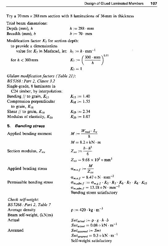
Design of Glued Laminated Members 107
Try a 70mm x 288 mm section with 8 laminations of 36mm in thickness
Trial beam dimensions: Depth (mm), h h := 288 mm Breadth (mm), b b:=70-mm Modification factor K7 for section depth:
to provide a dimensionless value for K7 in Mathcad, let: h1 := h * mm-l
for h < 300mm K7 ( h ) 300 + mm '*l1
K7 = 1
Glulam m o ~ ~ c a t i o n factors (Table 21): BS5268 : Part 2, Clause 3.2 Single-grade, 8 laminates in
Bending // to grain, K15 Compression perpendicular
Shear // to grain, KI9 Modulus of elasticity, Kz0
C24 timber, by interpolation:
to grain, K18
5. g e n ~ j n g stress
Applied bending moment
Section modulus, Zxx
Applied bending stress
Permissible bending stress
Check self-weight: BS 5268 : Part 2, Table 7 Average density Beam self-weight, (kN/m) Actual
Assumed
K15 := 1.40 K1g := 1.55
K19 := 2.34 K20 := 1.07
wmed * Le M := 8
p := 420 kg m-3

Structural Timber Design
ateraJ sta~iJity
Clause 2.10.8 and Table 16 h b Ends should be held in position and compression
aximum depth-to-breadth - = 4.11 ratio, hJb
edges held in line by direct connection o f decking to the beams
Q ear stress
Applied shear force
Applied shear stress
Fv = 7.54 o k N
Ta,f/ = 0.56 o N mm? Permissible shear stress, no notch := zg.i + K2 K3 K5 Kg K19
zah.i = 2.08 o N . mmv2 Shear stress satisfactory
Applied load
Applied bearing stress (bearing area = b bw)
Permissible bearing stress
Modulus of elasticity for glulam, E
Second moment o f area, Ixx
Deflection due to bending
F = 7.54 o kN

Design of Glued Laminated Members 10
19.2 * M (b * h) * E Deflection due to shear As :=
As = 0.68 o mm
Atotal = 10.71 o mm
A a h = 13.05 o mm Deflection okay and no pre-cambering is
Total deflection Atotal P= Am + As
Permissible deflection :=I= 0.003 L e
required
8 mm deep sections with 8 l a ~ n a t i ~ of 36 mm in thickne~
EEective length, L e Bearing width, bw Beam dimensions: Depth, h breadth, b
L e := 9.6 m bw := 175. mm
} Not known at this stage
Self-weight of beam (kN/m), Swt Swt := 0.7. kN . m" assumed Strip of load of width bj = 300 mm, see Fig. 6.8 (b), on the top of a main beam plus its self-weight
bj := 300 mm Long-term loading Pstrip.long := (DL bj + Swt) L e
Medium-term loading Pstrip.med := (DL + IL) * bj L e + S W t * L e
Point (concentrated) loading wlong from secondary beams (kN), PS ps.low := ' ~ 2
Pstrip.long 8-76 0 kN
Pstrip,med = 18.12 o kN
Ps.long L== 3.77 o kN
Total load (kN): Long-term, Piong
Medium-term, Pmed
K1 to KG are as above No load sharing applies
(Kg, Clause 2.9)
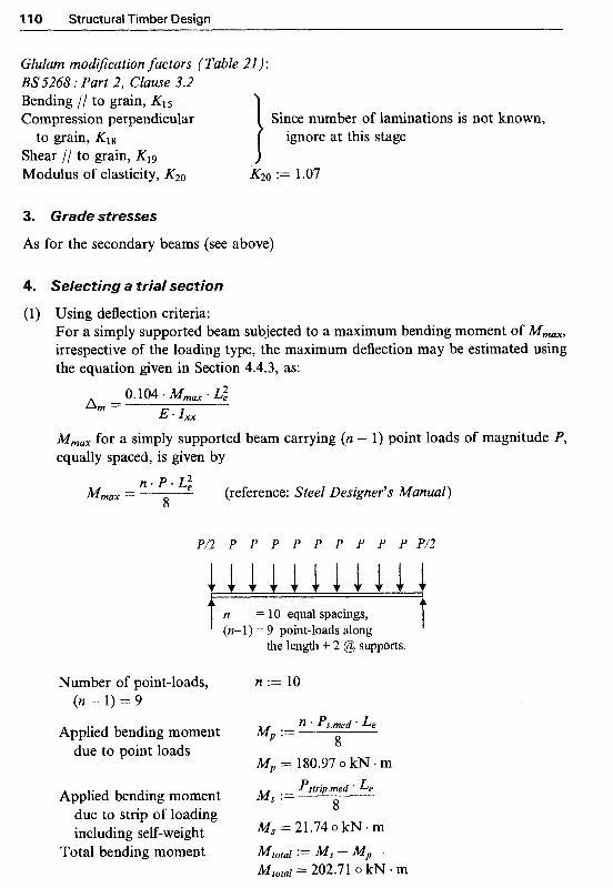
Structural Timber Design
Glularn ~ o d ~ c a t i o n factors (Table 21): BS5268: Part 2, Clause 3.2 Bending // to grain, K15 Compression pe~endicular Since number of lamination^ is not known,
Shear / I to grain, K19 Modulus of elasticity, KZ-, K20 := 1.07
to grain, K18 ignore at this stage
3. Grade stresses
As for the secondary beams (see above)
4. Selecting a trial section
(1) Using deflection criteria: For a simply supported beam subjected to a maximum bending moment of Mm,,, irrespective of the loading type, the maximum deflection may be estimated using the equation given in Section 4.4.3, as:
0.104 * M m , * L:
E * Ixx Am =
MmaX for a simply supported beam carrying (n - 1) point loads of magnitude P, equally spaced, is given by
ne P . L: 8 Mmax = (reference: Steel Designer's Manual)
P/2 P P P P P P P P P P / 2
11111111111 t n = 10 equal spacings,
(n-l) = 9 point-loads along t the length + 2 @ supports.
Number of point-loads, n := 10 ( n - 1 ) = 9
n * Ps.med * L e Applied bending moment MP := Iz
due to point loads U
MP = 180.97 o kN m
Applied bending moment MS := Pstrip.med * Le 0
due to strip of loading including self-weight MS =21.740kN.m
0
Total bending moment Mtotal := M S 4" MP Mtotal = 202.71 0 kN m

Design of Glued Laminated Members
odulus of elasticity for E := Em,,, - K20 glulam, E E = 1.16 x lo4 o N -mm"2
ermissible d e f o ~ a t i o n Au(ifn := 0.003 * L, &h = 28.8 o mm
0.104 0 Mlotal * L: Required second moment Ixx.rqd :=
E * of area, I,, using A,h IxX-rqd = 5.84 X io9 o mm4
Using lateral stability criteria: In order to achieve lateral stability by direct fixing of decking to beams, the depth- to-breadth ratio should be limited to 5, i.e. h 5 5b. Substituting for h = 5b in Ixx = bh3/i2 and equating it to Ixx,rqd:
b * (5 * b)3 12 Ixx,rqd = will give
and depth of the section, h
Try a 180 mm x 864 mm deep Trial beam dimensions: Depth (mm), h Breadth (mm), b
' S
b := ( 53 12 * Ixx.rqd
b = 153.86 o mm
h = 769.31 o mm ,ection with 24 laminations of 36mm in thickness
h : = 5 * b
h := 864 mm b := 180. mm
Modification factor K7 for section depth: To provide a dimensionless
value for K7 in Mathcad, let: h1 := h mm"
for h > 300mm h; + 92 300 K7 := 0.81 h: + 56 800
K7 = 0.85
~ l u l a ~ ~ o d ~ ~ a t i o n factors (Table 21) : BS5268 : Part 2, Clause 3.2 Single-grade, 24 laminates in
Bending // to grain, K15 K15 := 1.52 Compression perpendicular to K18 := 1.55
Shear // to grain, K19 K19 :==: 2.34 Modulus of elasticity, K20 K20 := 1.07
C24 timber
grain, K18
Total applied bending moment Mtotal = 202.71 o kN . m
Section modulus, Zxx b h2 zxx := -
Zxx = 2.24 x lo7 o mm3 6

11 2 Structural Timber Design
Applied bending stress nilt0taI 0 m . a . i
z x x
Gm.a,l/ = 9.05 0 N * mm-2
0 m . a h . I 12.05 0 N mm-2 Permissible bending stress om.adm.( Gm.g.1 * K2 K3 * K6 * K7 * K8 * K15
Bending stress satisfactory Check self-weight: BS.5268 : Part 2, Table 7 Average density Beam self-weight, (kNIm) Actual
Assumed
6 . ~ a t ~ r a J s t a ~ j i j t ~
Clause 2.10.8 and Table 16
Maximum depth-to-breadth ratio, h/b
Applied shear force
Applied shear stress
Permissible shear stress, no notch
Applied load
Applied bearing stress, (bearing area = b x bw)
p := 420 kg m-3
h b - = 4.8
Ends should be held in position and compression edges held in line by direct connection o f decking to the beams
Pmed Fv :=y L
Fv = 84.46 o kN
F-" Pmed *- 2
F = 84.46 o kN
0c.a.pp := (A) ( T , . , . ~ ~ = 2.68 o N mmw2
Design of Glued Laminated Members 11 3
Permissible bearing stress 0c.adm.pp := 0c.g.pp * K2 * K3 ' Kh ' K8 * K18 0 c . a h . p p = 3.68 o N mm-2 Bearing stress satisfactory
9. ~ e f l e c t i o ~
Modulus of elasticity for E := Emean K20 glulam, E E = 1.16 x lo4 o N a mmm2
b h3 12 Second moment of area, I,, I,, := -
I,, = 9.67 x lo9 o mm4
Deflection due to bending
Deflection due to shear
Total deflection
Permissible deflection
As = 2.17 o mm &,tal A m "I- Atotal = 19.54 o mm Aah := 0.003 * L e Aah = 28.8 o mm Deflection okay and no pre-cambering is required
Therefore adopt 180mm wide x 8 mm deep sections with 24 la~nations of 36 mm in thickness
Design of a curved glued laminated timber beam for the roof of a restaurant is required. The beam is to span 9.0m centre to centre supported on 250 mm wide bearings under service class 1 conditions. It is proposed to use a single grade lay-up using softwood timber in strength class Cl8 with horizontal laminations of 30mm finished thickness. The radius of curvature at mid-span bend is to be 6.5m. The beam is subjected to a dead load of 1.65 kN/m, including self-weight, and an imposed medium-term load of 2.25 kN/m.
Force, kN N :=newton Length, m kN := lo3. N Cross-sectional dimensions, mm Direction parallel to grain, // Stress, Nmm"2 Direction perpendicular to grain, pp
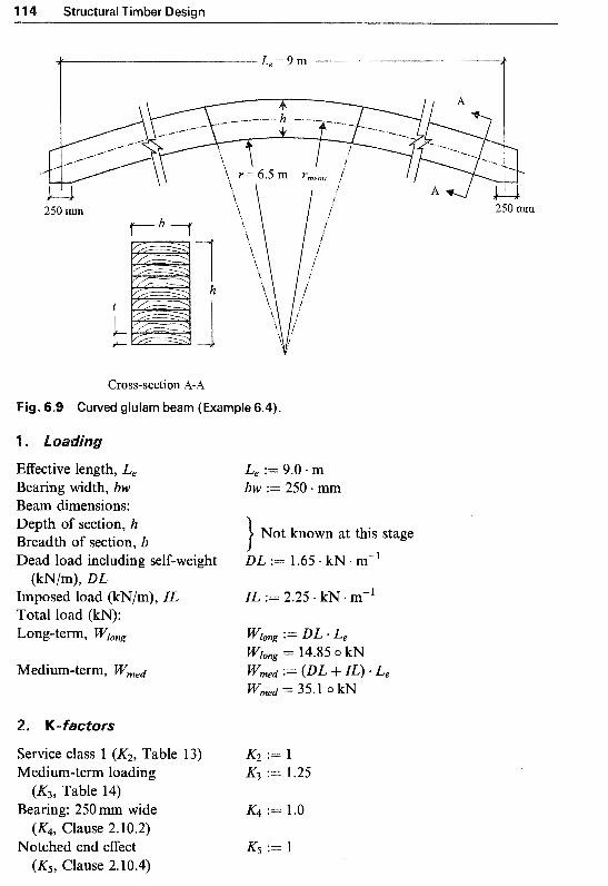
4 Structural Timber Design
250 m **\ \ 250 mtn
1 h
250 m
Cross-section A-A Fig. 6.9 Curved glulam beam (Example 6.4).
Effective length, L, Bearing width, bw Beam dimensions: Depth of section, h Breadth of section, b Dead load including self-weight
Imposed load (kN/m), IL Total load (kN): Long-term, W&
(kN/m), DL
Le := 9.0 m bw := 250 mm
Not known at this stage
DL := 1.65 kN m-1
IL := 2.25 kN m-’
Service class 1 (K2, Table 13) KZ := 1 Medium-term loading K3 := 1.25
Bearing: 250mm wide K4 := 1.0
Notched end effect K5 := l
(K3, Table 14)
(K4, Clause 2.10.2)
(K5, Clause 2.10.4)

Design of Glued Laminated Members l15
Form factor (K6, Clause 2.10.5) K6 := 1 Depth factor (KT, Clause 2.10.6) K7 := 1 assumed No load sharing (Ks, Clause 2.9) Kg := 1
Glulam mod~cation factors (Table 21): BS.5268: Part 2, Clause 3.2 Bending // to grain, K15 Compression perpendicular Since number of laminations is not known,
Shear // to grain, K19 Modulus of elasticity, K20 :== 1.17
3. Grade stresses
IPS5268 : Part 2, Clause 3.2 Table 7 , for C18 timber Bending // to grain Compression perpendicular
Shear // to grain Mean modulus of elasticity
i to grain, Kls ignore at this stage
to grain
Qm.g.// := 5.8 N mmv2 cT,.g.pp := 1.7 N mmv2
Selecting a trial section
Using deflection criteria: Modulus of elasticity E := Ernean * K20
Permissible deformation &h := 0.003 * Le for glulam, E E = 1.06 x 1040N.mm"2
&h = 27 o mm 5 * ZL * L: Required second moment Zxx.rqd :=
384 E * A a h of area, Zxx using Aah zxx.rqd = 6.69 X 10' o mm4
Using lateral stability criteria: In order to achieve lateral stability by direct fixing of decking to beams, the depth- to-breadth ratio should be limited to 5, i.e. h 5 5b. Substituting for h = 5b in zxx = bh3/12 and equating it to Zx-.rqd:
b * (5 12 * zxx.rqd 1/4 Zxx,rqd 12 will give b := ( 53 )
b = 89.51 o mm and depth of section, h h : = 5 . b
h = 447.55 o mm Try a 105 mm x 5 10 mm deep section with 17 laminations of 30 mm in thickness Trial beam dimensions: Depth (mm), h h := 510 mm Breadth (mm). b b := 105 - mm
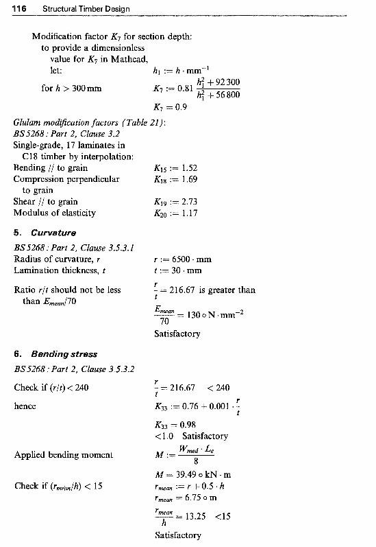
’l 16 Structural Timber Design
Modi~cation factor K? for section depth: to provide a dimensionless
value for K7 in Mathcad, let: h1 := h + mm-l
for h > 300mm h; + 92 300 h? -k 56 800
K7 := 0.81
G l u l a ~ ~ o d ~ c a t ~ o n factors (Table 21): BS5268 : Part 2, Clause 3.2 Single-grade, 17 laminates in
Bending // to grain Compression perpendicular
Shear // to grain Modulus of elasticity
C18 timber by interpolation:
to grain
BS5268: Part 2, Clause 3.5.3.1 Radius of curvature, r Lamination thickness, t
Ratio r/t should not be less than E,ea,J’70
K15 := 1.52 K18 := 1.69
K19 := 2.73 K20 := 1.17
r := 6500 - mm t := 30 mm r - = 216.67 is greater than t 27 &mean ”
70 _. 130 o N -mmm2
Satisfactory
BS5268 : Part 2, Clause 3.5.3.2
Check if ( r / t ) < 240
hence
Applied bending moment
Check if ( r ~ ~ ~ / h ) < 15
-= 216.67 < 240 r t K33 := 0.76 + 0.001 * - r
t K33 = 0.98 <l .O Satisfactory
M := 8
M = 39.49 o kN m
Wmed * L e
r m a n := r + 0.5. h r m a n = 6.75 o m r m a n
h ” - 13.25 <l5
Satisfactory
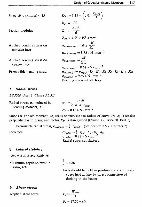
Design of Glued Laminated Members
Since 10 < (rmean/h) 5 15
Section modulus
Applied bending stress on concave face
Applied bending stress on convex face
Permissible bending stress K33
BS5268 : Part 2, Clause 3.5.3.3
Radial stress, G r , induced by CTr := 3."
2 * b * h * rmean bending moment, M, O r = 0.16 o N * mm-2
Since the applied moment, M, tends to increase the radius of curvature, Or is tension perpendicular to grain, and factor K19 is disregarded (Clause 3.2, BS 5268 : Part 2).
Permissible radial stress, G t . a h . p p = f T a h . 1 (see Section 2.5.7, Chapter 2) therefore
. ~ a t ~ r a f s~a~j f j t y
Clause 2J0.8 and Table 16
Maximum depth-to-breadth - = 4.86 h b
Ends should be held in position and compression ratio, h/b
edges held in line by direct connection of decking to the beams
. ear stress
Applied shear force Wmed Fv := ~ 2 F, = 17.55 o kN
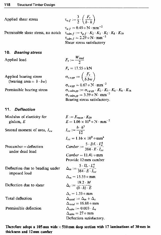
118 Structural Timber Design
Applied shear stress
Permissible shear stress, no notch
10. Bearing stress
Applied load
Applied bearing stress (bearing area = b + bw)
Permissible bearing stress
1 1. Reflection
Modulus of elasticity for glulam, E
Second moment of area, Z,,
Precamber = deflection under dead load
Deflection due to bending under imposed load
Deflection due to shear
Total deflection
Permissible deflection
Wmed Fv := 7 L,
Fv = 17.55 o kN
0c.a.pp := (A)
E := Emean * K20 E = 1.06 x lo4 o N mm-2
b h3 I,, := - 12 zxx = 1.16 X io9 omm4
5.DL.L: Camber := 384 * E Zxx Camber = 1 1.41 o mm Provide 12 mm camber
5 * IL * L: A m :=
384 * E * Zxx
A m = 15.55 o mm
a, := 19.2 * M (b * h) * E
h, = 1.33 o mm atotal := a m t- 4 Atoral = 16.88 o mm
:= 0.003 * L e
A a h = 27 o mm Deflection satisfactory.
Therefore adopt a 105 mm wide x 510mm deep section with 1'7 laminations of 30mm in thickness and 12mm camber
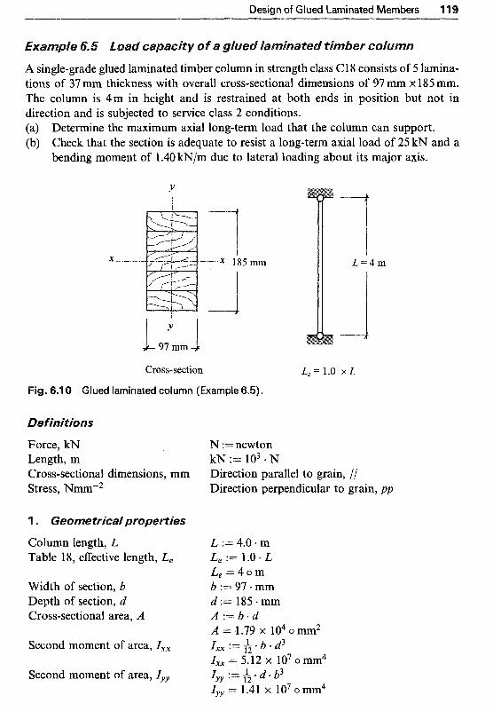
Design of Glued aminated ~ e m b e ~ s 1 7
A single-grade glued laminated timber column in strength class Cl8 consists of 5 lamina- tions of 37 mm thickness with overall cross-sectional dimensions of 9’7 mm x 185 mm. The column is 4m in height and is restrained at both ends in position but not in direction and is subjected to service class 2 conditions. (a) Determine the maximum axial long-term load that the column can support. (b) Check that the section is adequate to resist a long-term axial load of 25 kN and a
bending moment of 1.40 kN/m due to lateral loading about its major axis.
x -.-.-.
Y !
Cross-section L, = 1.0 x L
Fig. 6.1 0 Glued laminated column (Example 6.5).
Force, kN Length, m Cross-sectional dimensions, mm Stress, Nmm-2
Column length, L Table 18, effective length, L,
Width of section, b Depth of section, d Cross-sectional area, A
Second moment of area, I,,
Second moment of area, Iyy
N := newton kN := lo3 N Direction parallel to grain, // Direction perpendicular to grain, pp
L := 4.0 - m L, := 1.0 * L L , = 4 o m b := 97 .mm d := 185. mm
A = 1.79 x io4 o mm2
I,, = 5.12 x lo7 o mm4 lYy := d . b3
A : = b e d
Ixx := b * d3
rYY = 1.41 X io7 0mm4

120 Structural Timber Design
d For a rectangular section, radius of gyration, i,, lxx := 4 2
ixx = 53.4 o m
and iyy
Section modulus, Zxx
About x-x axis
About y-y axis
b lYY := 412
iyy = 28 o mm b * d2 zxx := -
zXx = 5.53 x io5 o mm3 6
L e h, := y"
h, = 74.9 -L2 hyy := - iYY
lxx
hyy = 142.85 < 180 satisfactory
BS.5268 : Part 2, Table 7 Strength class, C18 timber Bending // to grain CF,.~,J := 5.8 N mm"2 Compression parallel to grain C F ~ . ~ . ~ := 7.1 N + mm"2 Minimum modulus of elasticity Emin := 6000 . N mm-2 Mean modulus of elasticity Emean := 9 100 * N * mm-2
Service class 2 (K2, Table 13) K2 := 1 Long-term loading (K3, Table 14) K3 := 1 Form factor (&, Clause 2.10.5) K6 := 1
Depth factor (.K7, Clause 2.10.6) K7 := ( ) No load sharing (K8, Clauses 2.9 K8 := l
300 mm
K7 = 1.05
and 2.1 1.5)
( 4 ~ l u i a m m o d ~ c a t i o ~ factors: Since buckling is critical about column's minor axis, i.e. y-y axis, the behaviour under axial loading only is similar to the vertically laminated members and hence the
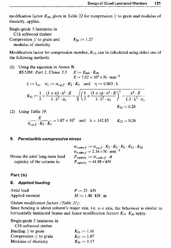
Design of Glued Laminated Members 421
modification factor K28, given in Table 22 for compression // to grain and modulus of elasticity, applies.
Single-grade 5 laminates in Cl 8 softwood timber:
Compression // to grain and K2g := 1.27 modulus of elasticity
~odification factor for compression member, KI2, can be calculated using either one of the following methods:
(1) Using the equation in Annex B: BS5268 : Part 2, Clause 3.3 E := Emin * K2g
E = 7.62 x lo3 o N mmn2 h := hyy G, := cTCsg.I K2 - K3 and := 0.005 h
K12 = 0.26 (2) Using Table 19:
E = 1.07 x lo3 and h = 142.85 K12 = 0.26
%.g./ * K2 * K3
s s i ~ ~ e ~ o ~ ~ r e s s i v e S
Axial load Applied moment
~lulam mod~cation factors (Table 21): Since bending is about column's major axis, i.e. x-x axis, the behaviour is similar to horizontally laminated beams and hence modification factors K15-K20 apply,
Single-grade 5 laminates in C18 softwood timber
Bending // to grain K15 := 1.16 Compression // to grain K17 := 1.07 Modulus of elasticity K20 := 1.17

1 Structural Timber Design
~ o d i ~ c a t i o n factor for compression member, KI2, can be calculated using either one of the following methods:
(l) Using the equation in Annex B: BS.5268 : Part 2, Clause 3.6 E := Ernean * K20
E = 1.06 x lo4 o N. mm"2
h := hyy G, := K2 K3 and := 0.005 h
K12 := - 1 + ( l+q)*7t2 .E-{( l -+ ( l + q ) - n 2 . E 2 3*h2.cTc 2 3 .h2 .Uc 1.5 S h2 m c~,
K12 = 0.32 (2) Using Table 19:
E = 1.5 x lo3 and h = 142.85 K12 = 0.32 oc.g.1 * K2 K3
7. ~ o ~ ~ r e s s i o n and bendjng stresses P Applied compressive stress oc.a.1 *- -
*- A = 1.39 o N mmw2
Permissible compressive stress oc.adm.l := cTc.g.l K2 - K3 Kg K12 K17 c ~ ~ . ~ ~ . 1 := 2 . 4 4 o ~ . m m - ~ Compressive stress satisfactory
Applied bending stress
Permissible bending stress
Check interaction quantity
Euler critical stress
om.a .1 oc.a.1 +- Dc.adm.1
= 0.98 < 1 Interaction quantity is satisfactory
Therefore a 97 mm x 185 mm section with 5 laminations of 37 mm timber in stren~th class C18 is satisfactory

Chapter 7 esign of Ply-webbed
A ply-webbed beam comprises three main parts, namely flanges, web(s) and glued or nailed joints between flanges and web(s). The flanges are generally made of solid structural timber sections finger-jointed together to produce the required length. The web(s) are made of plywood, although other wood- based materials such as particleboard or fibreboard may also be used. The flanges are often connected to plywood web(s) by structural timber adhesives in an industrial process, or sometimes by mechanical fasteners such as nails.
Ply-webbed beams are usually of I or boxed shapes. Typical cross-sections of ply-box and I beams which are symmetrical about both vertical and horizontal axes are shown in Fig. 7.1.
Ply-webbed beams owe their structural advantage to plywood acting as a shear-resistant material for the webs, allowing the solid timber sections to be spaced apart. This permits saving in materials and provides extra stiffness and strength for the beams. Ply-webbed beams are widely used for spans in excess of those for which solid timber is suitable, i.e. for spans greater than
x x - x a H
Fig. 7.1 I and boxed ply-webbed beams.
123

4 Structural Timber Design
5 m and often up to 10-1 5 m. Their commonest application is in roof con- struction, where parallel top and bottom flanges may be used to give a flat roof or the upper profile may be pitched'.
Fly-webbed beams have also been used as a type of large span (30m or more) built-up portal frame in bridge construction. In addition, the good strength to weight performance of ply-webbed beams makes them an attract- ive option for construction of large cross-sectioned beams. For example as a hollow interior boxed bridge construction for a covered pedestrian crossing or as a prefabricated housing unit'.
In this chapter, design recommendations for the most common method of construction, i.e. glued ply-webbed beams, are discussed. The recom- mendations may also be applied, with some modification, to all nailed ply- webbed beams.
In general a ply-webbed beam is built with materials which have different moduli of elasticity, which lead to development of different stress magnitudes at the same depth. In Fig. '7.2 an example of differences in stress values for the two beam profiles subjected to bending moment is illustrated.
For a ply-webbed beam comprising materials with different moduli of elasticity, it is common practice to calculate the efective geometrical prop- erties of the cross-section using a technique known as transformed section me t~od . In this method the whole cross-section is considered as acting as one homogeneous material with the same properties as say the flange material, where the contribution from the web(s) is altered in proportion to the ratio of the moduli of elasticity.
bl2 t bl2
-
I i %nber
(7inzber : I
Fig. 7.2 Bending stresses in ply-webbed beams.
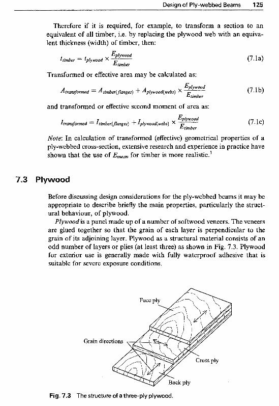
Design of Ply-webbed Beams 125
Therefore if it is required, for example, to transform a section to an equivalent of all timber, i.e. by replacing the plywood web with an equiva- lent thickness (width) of timber, then:
- -fiplywood
ttimber = tplywood x - Etirnber
Transformed or effective area may be calculated as: Eplywood
Atrawformed = Atimber(~a~ges) $- Ap~ywood(web~) x ~
E t i d e r
and transformed or effective second moment of area as: Eplywood
Etimber Itramformed = r ~ ~ b e r ~ ~ ~ g e s ) $- ~plywood(webs) x
(7. la)
(7.1 b)
(7. IC)
Note: In calculation of transformed (effective) geometrical properties of a ply-webbed cross-section, extensive research and experience in practice have shown that the use of Ernean for timber is more realistic.'
Before discussing design considerations for the ply-webbed beams it may be appropriate to describe briefly the main properties, particularly the struct- ural behaviour, of plywood.
Plywoodis a panel made up of a number of softwood veneers. The veneers are glued together so that the grain of each layer is perpendicular to the grain of its adjoining layer. Plywood as a structural material consists of an odd number of layers or plies (at least three) as shown in Fig. 7.3. Plywood for exterior use is generally made with fully waterproof adhesive that is suitable for severe exposure conditions.
h
Grain
Cross ply
Back ply
Fig. 7.3 The structure of a three-ply plywood.

126 Structural Timber Design
The structural properties and strength of plywood depend mainly on the number and thickness of each ply, the species and grade, and the arrangement of the individual plies. As with timber, load factors such as type of applied stresses, their direction with respect to grain direction of face ply and duration of loading have great influence on the structural properties of plywood.
Plywood may be subjected to bending in two different planes depending on its intended use and the direction of the applied stress and therefore it is important to differentiate between them:
(1) Bending about either of the axes (i.e. x-x or y-y) in the plane of the board, as shown in Fig. 7.4(a), for example in situations where it is used as shelving or as floorboard.
(2) Bending about an axis perpendicular to the plane of the panel (i.e. z-z), as shown in Fig. 7,4(b), for example when it is acting as a web of a flexural member such as in ply-webbed beams.
/
x
(a) Bending about either of the axes in the plane of the board.
(b) Bending about an axis perpendicular to the plane of the board.
Fig. 7.4 Plywood - axes of bending.
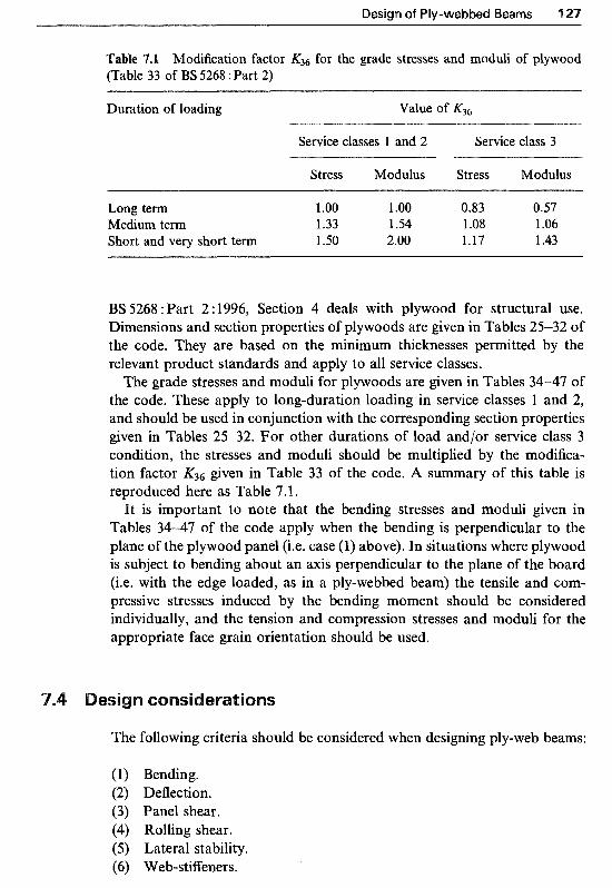
Design of Ply-webbed Beams 'l 27
Table 7.1 Modification factor K36 for the grade stresses and moduli of plywood (Table 33 of BS 5268 :Part 2)
Duration of loading Value of K36
Service classes 1 and 2 Service class 3
Stress Modulus Stress Modulus ~"
Long term 1 '00 1 .oo 0.83 0.57 Medium term 1.33 1 S4 l .08 1.06 Short and very short term 1.50 2.00 1.17 1.43
BS 5268 : Part 2 : 1996, Section 4 deals with plywood for structural use. Dimensions and section properties of plywoods are given in Tables 25-32 of the code. They are based on the minimum thicknesses permitted by the relevant product standards and apply to all service classes.
The grade stresses and moduli for plywoods are given in Tables 34-47 of the code. These apply to long-duration loading in service classes 1 and 2, and should be used in conjunction with the corresponding section properties given in Tables 25-32. For other durations of load andlor service class 3 condition, the stresses and moduli should be multiplied by the modifica- tion factor K36 given in Table 33 of the code. A summary of this table is reproduced here as Table 7.1.
It is important to note that the bending stresses and moduli given in Tables 34-47 of the code apply when the bending is perpendicular to the plane of the plywood panel (i.e. case (1) above). In situations where plywood is subject to bending about an axis perpendicular to the plane of the board (i.e. with the edge loaded, as in a ply-webbed beam) the tensile and com- pressive stresses induced by the bending moment should be considered individually, and the tension and compression stresses and moduli for the appropriate face grain orientation should be used.
The following criteria should be considered when designing ply-web beams:
(1) Bending. (2) Deflection. (3) Panel shear. (4) Rolling shear. (5) Lateral stability. (6) Web-stiffeners.
128 Structural Timber Design
BS 5268 :Part 2, Clause 4.6 deals with the use of plywood in flexural members. The permissible stresses for plywood in flexural members are governed by the particular conditions of service and loading described in Clauses 2.8 and 2.9 of the code (which relate to load duration and load sharing respectively) and should be taken as the product of the grade stresses given in Tables 34-47 and the modification factor from Table 33 of the code (Table 7.1).
BS 5268 : Part 2, Clause 2.10.10 specifies that the modification factors K27, K28 and K29 (for glulam members) given in Table 22 may also be used for the flanges of glued built-up beams such as I and box ply-webbed beams. The number of pieces of timber in each flange should be taken as the number of laminations, irrespective of their orientation, to determine the value of the stress modification factors K27, and K29 for that flange.
As mentioned earlier, the plywood web(s) of a ply-webbed beam will be subjected to bending about an axis perpendicular to the plane of the board; and it is therefore necessary to check that the maximum applied bending stress in the transformed section is not greater than the lesser of:
(1) the permissible tensile stress of the timber flange, Ufimber,t,adm,/
(2) the permissible compressive stress of the timber flange, U t i ~ b ~ r , c , u d m , / (3) the permissible transformed tensile stress of the plywood web,
- Bplywood
=p lywood , t , a~ , / -"-. Ef imber
and (4) the permissible transformed compressive stress of the plywood web,
Eplywood uplywood,c,adm,/ ' p
Etimber
Therefore the applied bending stress in the transformed section, Om,u , / ,
should not be greater than the lesser of the above permissible stresses, where,
the permissible tensile stress for timber flanges is
the permissible compressive stress for timber flanges is
=tjmber,c,adm,/ = grade Stress (Table 719 oc,g,/ x K$3K&28 (7.2b)
and for plywood web(s), the permissible tensile or compressive stress is
Eplywood
Etirnber X"----- K8K36 (7 .2~ & d)

Design of Ply-webbed Beams 129
7.4.2
The applied bending stress for a beam subjected to a maximum bending moment of M can be calculated from:
Ixx H BH3 ba3 where: Zxx = - y = y and Ixx=--- 12 12 Y a, b, B and H are as indicated in Fig. 7.1.
Deflection
Generally, in composite constructions, such as ply-webbed beams, the plane cross-sections of the beam do not remain plane during bending, as assumed in simple theory. This leads to increased deformation due to shear. Therefore deflection of a ply-webbed beam, as mentioned in Section 4.4, is determined as the sum of deflections due to bending, A m , and shear, A,:
Atotal = A m + As (7.4)
For deflection calculations Clause 12.10.10 of the code also states that the total number of pieces of timber in both flanges should be taken as the number of laminations necessary to determine the value of K28 that is to be applied to the minimum modulus of elasticity, Emin.
Bending deflection, Am, for a simply supported beam carrying a uniformly distributed load of w/m, may be calculated from:
and for a simply supported beam carrying a concentrated load of p at mid-span, from:
where: E= Emin (for timber) x K28 (for the total number of flanges in the
I= second moment of area of the transformed section. Shear deflection, A,. There are many methods available to estimate the shear deflection in ply-webbed beams. However, for a simply sup- ported beam, based on Roark’s recommended approximation (1956); the shear deflection may be estimated from:
beam, Table 22)
M A, = - GwAw (7.7)
1 Structural Timber Design
where:
Gw= the modulus of rigidity (shear modulus) of plywood web A the area of the plywood web (actual, not transformed).
M = the bending moment at mid-span
-4.3 ~ a ~ e / shear
Applied panel shear, z,, is the horizontal shear stress induced in a plywood web and can be calculated from:
Z" Ijy Q
a - I - t
where: E; = maximum shear force (usually maximum reaction) Q =first moment about the neutral axis of the transformed section area
above the axis I= second moment of area of the whole transformed section t = total thickness of the plywood (actual, not transformed).
Applied panel shear, za, should not be greater than the permissible panel shear for plywood web, zplywood,adm:
Ta 5 Zplywood,adm
The term rolling shear is used to describe a failure mode which may result due to overstressing of the glue line between the flange and yeb of a beam by shear force(s) acting at the interface. This is due to the physical construction of plywood (i.e. having ply grains at 90" to each other), which enables the material fibres to roll across each other, creating a shear failure plane. The rolling shear stress will occur in veneer which has vertical grain. If face grain is vertical, the rolling shear will occur in the veneer that is glued to the flange. If the face grain is parallel to the flange, it will occur in the second veneer or the first glue line. In order to avoid rolling action taking place, the rolling shear must be limited by providing sufficient glued contact depth between the flange and web.
A simplified equation for calculation of applied rolling shear stress, z,,,, is given by:
(7.10)

Design of Ply-webbed Beams 131
where: F,, = maximum shear force (usually maximum reaction) Qr = first moment of area of upper flange about neutral axis
h =contact depth (depth of flange) I = second moment of area of whole transformed section.
BS 5268 :Part 2, Clause 4.6 recommends that for rolling shear at the junction of the web and flange of a ply-webbed beam, and at the junction of the outmost longitudinal member, the grade stresses given in Tables 34-47 should be multiplied by the stress concentration modification factor, K37,
which has the value 0.5. Applied rolling shear stress, Tr,a, should be less than or equal to permis-
sible rolling shear stress Tr,a I Tr,adm
where: T r , a h =grade stress, Tr,g X K8K3&37 and K37 = 0.5 (7.1 1)
7.45; Lateralstability
Lateral stability of I and box beams should be checked with reference to Clause 2.10.10 of BS 5268 : Part 2. A summary of this clause is given below.
The ratio of the second moment of area of the cross-section about the neutral axis, Ixx, to the second moment of area about the axis perpendicular to the neutral axis, IYY, should be checked to ensure that there is no risk of buckling under design load. This is achieved by following the code's recommendations as summarised in Table 7.2.
7.4.6 Web-stiffeners
Clause 2.10.10 of BS 5268 : Part 2 recommends that built-up members with thin webs, i.e. I and boxed ply-webbed beams, should be provided with
Table '7.2 Recommendations for lateral support for ply-webbed beams (Clause 2.10.10, BS 5268 : Part 2)
Degree of lateral support Ratio Ixx]Iy,,
(a) No lateral support is necessary 5 or less (b) Ends of the beam should be held in position at the between 5 and 10
(c) The beam should be held in line at the ends between 10 and 20 (d) One edge should be held in line between 20 and 30 (e) The beam should be restrained by bridging or other between 30 and 40
(f) The compression flange should be fully restrained greater than 40
bottom flange at the supports
bracing at intervals of not more than 2.4m

Structural Timber Design
Web-stiffeners each side
Web-stiffeners in an l-beam.
web-stiffeners at all points of concentrated load including support posi- tions or elsewhere as may be necessary.
Since there is no definite guidance available on the positioning of web- stiffeners along the length of the beam, the manufacturers of ply-webbed beams often have to revert to tests to prove the chosen centres, or adopt a conservative approach by placing stiffeners closer than probably required. In Fig. 7.5 web-stiffeners in an I-beam are illustrated.
S
l . Mettem, C. J. (1986) Structural Timber Design and Technology. Longman
2. Roark, R. J. (1956) Formulas for Stress and Strain. 4th edn. McGraw-Hill, Scientific and Technical, Harlow,
NewYork.
a ~ ~ / e 7.1 Design ofa ~ / y - ~ e b b e ~ box b e a ~
Show that a glued ply-webbed box-beam with cross-sectional details as indicated in Fig. 7.6 is suitable for carrying a long-term uniformly distributed load of l .95 kN/m including self-weight over an effective span of 6.5 m in service class 2.
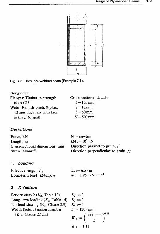
Design of Ply-webbed Beams 133
Fig. 7.6 Box ply-webbed beam (Example 7.1 ).
Design data Flanges: Timber in strength
class C16 Webs: Finnish birch, 9-plies,
12 mm thickness with face grain // to span
Force, kN Length, m Cross-sectional dimensions, mm Stress, Nmm-2
Effective length, L, Long-term load (kN/m), W
Service class 2 (IC2? Table 13)
Cross-sectional details: b= 120mm t = l2mm h=60mm
H= 5oomm
N :=newton kN := lo3 N Direction parallel to grain, // Direction perpendicular to grain, pp
L, := 6.5 . m W := 1.95 kN m"*
K2 := 1 Long-term loading (IC3? Table 14) K3 := 1 No load sharing (Kg, Clause 2.9) Kg := 1 Width factor, tension member b := 120 mm
(K14, Clause 2.12.2)
K14 = 1.11

4 34 Structural Timber Design
Clause 2.60.60 Tension l/, (K27, Table 22) K27 := 1 for one glued timber section per flange Compression //, (K280 Table 22) && := 1 for one glued timber section per flange Modulus of elasticity for := 1 .l4 for a total of two glued timber
deflection (Kz~E, Table 22) sections in both flanges
Clause 4.5 Plywood grade stresses K36s := 1.0
(&as, Table 33) Plywood moduli, ( K 3 6 ~ , Table 33) K 3 6 ~ := 1.0 Plywood rolling shear, K37 := 0.5
(K37, Clause 4.6)
3. Grade stresses
BS.5268 : Part 2, Table 7 Strength class, Cl 6 timber Tension // to grain CTthbet.t.g./ := 3.2 - N + mm-2 Compression // to grain CFtimber,c.g./ := 6.8 * N * mme2 Shear // to grain Ttimber,g./ := 0.67 * N mm"2 Mean E value Ethber.mean := 8800 * N * mm"2 Minimum E value Ethber.min := 5800 * N * mm"2
BS.5268 : Part 2, Table 40 Finnish birch, 9-plies, 12 mm plywood Tension // to face grain op~y.t .g.~ := 19.16 N m n r 2 Compression // to face grain C T ~ ~ ~ . ~ . ~ . / := 9.8 - N mm-2 Panel shear // and perpendicular zply.g := 4.83 6 N * mm-2
Rolling shear Tr.g := 1.23 N a mm"2 Modulus of elasticity in tension Eply := 4250 N mme2
to face grain
and compression // to face grain
(shear modulus) Modulus of rigidity G, := 320 * N * IXIIII-~
4. Geometrical properties
Transform section to an equivalent of all timber. Using Ernean for timber Etimber := E;imber.mean
Plywood thickness tply := 12 * mm
Transformed web thickness, tply.tfd := tply * EPrv tply.tfd
timber
tp[y.ffd = 5.8 0 mm

Design of Ply-webbed Beams 135
Transformed section: Cross-sectional dimensions: b := 120. mm
B := 2 * tply.tfd 4- b B = 131.59 o mm H := 500 + mm h := 60. mm a : = H - 2 . h a=380omm
B - H 3 b . a 3 Second moment of area, Zxx Ixx := - ~ - 12 12
Zxx = 8.22 x lo8 o mm4
Section modulus, Zxx
zXx = 3.29 x lo6 o mm3 H . B 3 aeb3
Second moment of area, Zyy zyy ;= - - - 12 12 Iyy = 4.02 x lo7 o mm4
5. g e ~ ~ i ~ g stress
The maximum applied bending stress in transformed section should not be greater than the lesser of:
(4) Transformed plywood otfd.ply.c.adm./ := oply.c.g./ * G' &'ly Kg K36s compression // to face grain
otfd.ply.c.adm./ = 4.73 N ' Thus, the lowest value is taken as the permissible stress in bending
Applied load, W W = 1.95 o kN m-'
Applied bending moment, M 1" := -
otimber.t.adm./ = 3*54 * mm-2
W a L: 8
M = 10.3 o kN m

II 36 Structural Timber Design
Applied bending stress, Om.a.1
Om.,./ = 3.13 o N * mm-2 Bending stress satisfactory
6. Deflection
BS5268: Part 2, Clause 2.10.10 Modulus of elasticity for
deflection
Deflection due to bending
Web area, A ,
Deflection due to shear
Total deflection
Permissible deflection
TI. Panel shear
Applied shear force, F,,
First moment of area, Q
Applied panel shear stress, z,
Permissible panel shear
8. ~ol l ing shear
Applied shear force, F,,
First moment o f area o f upper flange, Qr
E := Etimber.min ' K28E E = 6.61 x lo3 o N (I mm-2
5.W.L: A m :=
384 E * Ixx A m = 8.34 o mm A , := 2 * ( H - tply) A , = 1.2 X lo4 0 m2
A4 As := - G, * A ,
As = 2.68 o mm
Atotal = 1 1.02 o mm &*tal := A m + As
&h := 0.003 * Le A a h = 19.5 o mm Deflection satisfactory
F,, = 6.34 o kN
Q = 1.95 x lo6 o mm3
2 , = 0.63 0 N * mm-2 zadm./ := zp1y.g ' K8 K36s Tab./ = 4.83 ~ N . m m - ~ Panel shear satisfactory
F,, = 6.34 o kN
Q r = 1.58 X lo6 0mm3

Design of Ply-webbed Beams 137
F v * Qr 2 * h I,,
Applied rolling shear stress, z, zu :=
BS 5268: Part 2, Clause 30 Permissible panel shear
9. Lateral stability
Clause 2.1OJO
Check Ixx/Iyy ratio
z, = 0.1 o N . mm-2 zr.g = 1 2 3 o N * m"2 K37 := 0.5 zudm := %,g ' K8 * K368 * K37 zU& = 0.61 o N mm-2 Rolling shear satisfactory
&x __
IYY - - 20.44
Condition (d) applies, i.e. one edge should be held in line
Therefore the section is adequate
Example 7.2 Design of a ply- webbed /-beam
An office building has a flat roof which comprises ply-webbed I-beams spaced at 1.1 m centres with an effective span of 7.6rn. The I-beams support solid-section timber secondary beams that are finished flush with their top and bottom flanges and are positioned perpendicular to their longitudinal axes. Carry out design calculations to show that beams of glued construction with cross-sectional details indicated below in service class 2 are adequate. Design data Dead load including Given
self-weight = 0.8 1 kN/m2 b=47mm Imposed load h=97mm
(medium-term) = 0.75 kN/m2 t = 12mm Flanges: Timber in strength H= 580mm
class Cl 8 Web: Finnish conifer, 9-plies,
12 mm thickness l .4 mm veneer sanded with face ply grain perpendicular to span
Definitions
Force, kN N := newton Length, m k~ := 103 . N Cross-sectional dimensions, mm Direction parallel to grain, // Stress, Nmm-2 Direction perpendicular to grain, pp
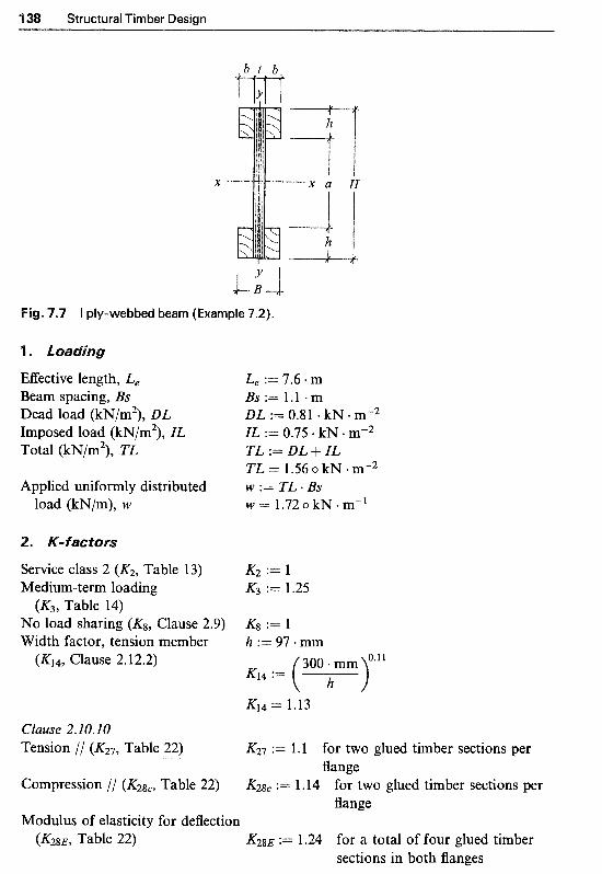
1 Structural Timber Design
4"L.l Fig. 7.7 I ply-webbed beam (Example 7.2).
EEective length, Le Le := 7.6 * m Beam spacing, Bs Bs:= 1.1 . m Dead load (kN/m2), DL DL := 0.81 a kN mW2 Imposed load (kN/m2), IL ZL := 0.75. kN mV2 Total (kN/m2), TL TL := DL + ZL
TL = 1.56 o kN +my2 Applied uniformly distributed W := TL . BS
load (kN/m), W W = 1.72 o kN m-l
Service class 2 (K2, Table 13) K2 := l Medium-term loading K3 := 1.25
No load sharing (lug, Clause 2.9) K8 := 1 Width factor, tension member h := 97 mm
(K3, Table 14)
(Kl4, Clause 2.12.2) K14 := ( h >".l1
300 - mm
K14 = 1.13 Clause 2.10.10 Tension // (&, Table 22) K27 := 1. l for two glued timber sections per
Compression // (K2gC, Table 22) := 1.14 for two glued timber sections per
Modulus of elasticity for deflection
flange
fl ange
Table 22) K28E := 1.24 for a total of four glued timber sections in both flanges
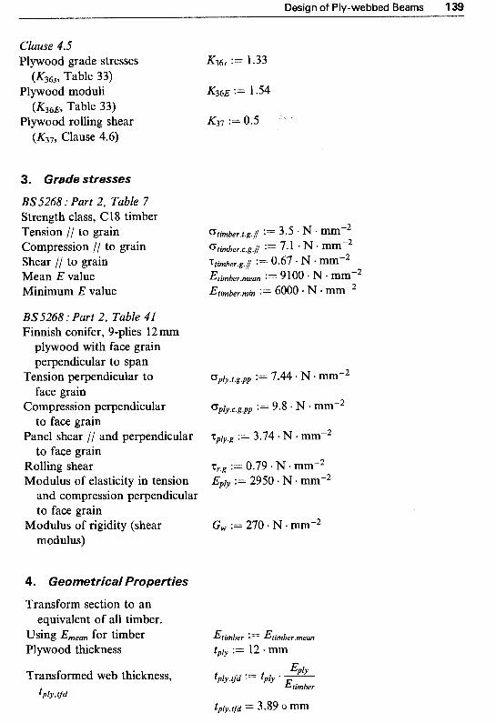
Design of Ply-webbed Beams 139
Clause 4.5 Plywood grade stresses K36s := 1.33
Plywood moduli K36E := 1.54
Plywood rolling shear K37 := 0.5
( K ~ G ~ , Table 33)
(K36~ , Table 33)
(K37, Clause 4.6)
3. Grade stresses
BS5268 : Part 2, Table 7 Strength class, C18 timber Tension // to grain Compression // to grain Shear // to grain Mean E value Minimum E value
BS5268 : Part 2, Table 41 Finnish conifer, 9-plies 12 mm
plywood with face grain perpendicular to span
face grain
to face grain
to face grain
Tension perpendicular to Dply.t.g.pp := 7.44 N mm"2
Compression perpendicular c ~ ~ ~ ~ . ~ . ~ . ~ ~ := 9.8 N mmM2
Panel shear // and perpendicular ?;ply.g := 3.74 + N mm-2
Rolling shear := 0.79 - N mmm2 Modulus o f elasticity in tension Eply := 2950 N mm-2
and compression perpendicular to face grain
modulus) Modulus of rigidity (shear G, := 270. N e mm"2
4. Geometrica/ Properties
Transform section to an
Using Ernean for timber Etimber := Etimbermean
Plywood thickness tply := l:! mm
equivalent o f all timber.
Transformed web thickness, tply.tfd := tply * - APlY Etimber
tply, tfd tply.tfd = 3.89 o mm

1 Structural Timber Design
Transformed section: ~ross-sectional dimension: b := 47 .mm
l? := tply.tfd + b . 2 B = 97.89 o mm H := 580 + mm h := 97 -mm a : = H - : ! . h a = 386omm
Second moment of area, I,,
Section modulus, Z,,
Second moment of area, ZYY
B - H3 ( 2 . 6 ) . a 3 12 12
zx, := - - = 1.14 X io9 0mm4
zyy = 1.52 X io7 o mm4
The ma~imum applied bending stress in transformed section should not be greater than the lesser of:
Timber tension // to grain
Timber compression// to grain
Transformed plywood tension perpendicular to face grain
Transformed plywood compression perpendicular to face grain
~qd.ply.c.adm.pp := 0ply.c.g.pp * & K368 timber
Thus, the lowest value is taken as the permissible stress in bending G#d.ply.t.adm.pp = 3-21 N * mm-2
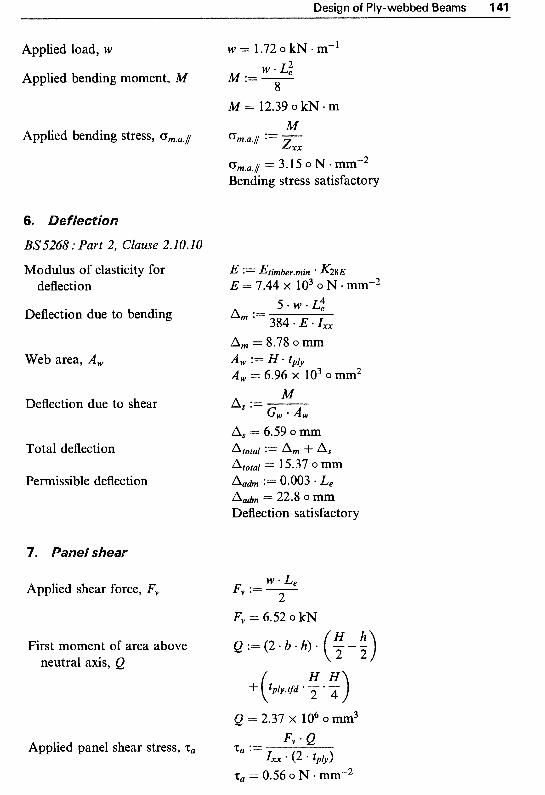
Design of Ply-webbed Beams 141
Applied load, W W = 1.72 0 kN * m-'
Applied bending moment, M M ;= - W ' L: 8
M = 12.39 o kN * m M
Applied bending stress, CFm.a.1 om.u.1 := - Z X X
C F ~ . , . ~ = 3.15 o N mm-2 Bending stress satisfactory
BS5268 : Part 2, Clause 2.10.10
Modulus of elasticity for deflection
Deflection due to bending
Web area, A,
Deflection due to shear
Total deflection
Pe~iss ib le deflection
E Etimber.min ' K28E E = 7 . 4 4 ; ~ 1 0 3 ~ N * m m " 2
5.W.L: Am := 384 * E * .IXX
A, = 8.78 o A, := H * tply A , = 6.96 x lo3 o mm2
M A, := - G, * A ,
A, = 6.59 o
Atoral := A m + a s Atoral = 15.37 o mm A a h := 0.003 * L e
A,& = 22.8 o Deflection satisfactory
W * L e
2 Applied shear force, F,, F,, := -
Fv = 6.52 o kN
First moment of area above neutral axis, Q
Q = 2.37 x lo6 o mm3 Fv * e
IXX * (2 * tply) Applied panel shear stress, za z, :=
z, = 0.56 o N mm-2

142 Structural Timber Design
Permissible panel shear Tach./ := zp1y.g K8 * K36s zah . / = 4.9’7 ~ N . m m - ~ Panel shear satisfactory
8. Rolling shear
Applied shear force, F, F, = 6.52 o kN
First moment of area of upper Q r := (2 a b flange above neutral axis, Qr
Q r = 2.2 X lo6 o mm3 Fv * Qr
2 * h Zxx Applied rolling shear stress, zu :=
= 0.06 o N * BS 5268 : Part 2, Clause 30 K37 := 0.5 permissible panel shear z u h := %.g * K8 * K36s * K37
z u h = 0.53 o N mm-2 Rolling shear satisfactory
9. Lateralstability
Clause 2.10.10
Check Zxx/Zyy ratio zxx
ZYJJ Condition (f) applies, i.e. compreSsion flanges
should be fully restrained, for example, by direct fixing of roof sheeting
” - 75.24
Therefore the section is adequate

Timber columns may be classified as simple or built-up, depending on their method of construction. Simple columns are fabricated from sawn timber or from glued laminated sections (glulam) to form one piece, for example, a rect- angular section, The design requirements for simple columns are discussed in detail in Chapters 5 and 6 for sawn solid sections and glulam members respectively.
~uilt-up columns are those composed of two or more sections of timber connected together either by gluing or by means of mechanical fasteners (such as nails, bolts, etc.) Such columns can provide considerably more strength than the sum of the strength of the sections acting alone. Built-up columns can be constructed in a great variety of shapes, see Fig. 8.1, to meet special needs or to provide larger cross-sections than are ordinarily avail- able, or purely for architectural applications. While glued built-up columns can be assumed to behave as a single member, the full composite strength development in mechanically fastened columns is doubtful. In general mechanically fastened columns may not possess adequate composite action by the connectors to make them act as a unit. In such cases designers are recommended to revert to prototype testing or conservative design solution.' BS 5268 : Part 2 : 1996 provides guidance for design of a special type of built- up column known as a spaced column which is detailed in this chapter.
Fig. 8.1 Typical cross-sections for built-up elements.
143

1 Structural Timber Design
Spaced c o Z ~ ~ n s are those built up as two or more individual members (shafts) with their longitudinal axes parallel, and are separated at the ends and mid-points with spacer bZocks and joined together by gluing, nailing, bolting or other means of timber connectors. A typical make-up of a spaced column is illustrated in Fig. 8.2. "he spacer blocks are provided to restrain differential movement between the shafts and to maintain their initial spacing under the action of load. The end connectors provide partial fixity to the individual members of the column, thus effectively restraining their buckling tendency. Spaced columns are often used in architectural applica- tions, in trusses as compression chords, and in frame construction.
A spaced column, due to the geometry of its cross-section, could have at least 25% more load-carrying capacity than a single solid member with a similar volume of timber. Spaced columns, apart from being economical, can provide suitable construction through which other pieces such as bracing or column to truss connections can be inserted conveniently.
Suitable connections (mechanical or glued)
Spacer blocks <
x -
Direction A
."
Direction B
Cross-section
-i
View in View in direction A direction B
c
L
7'
.2 Details of a two-shaft spaced column.
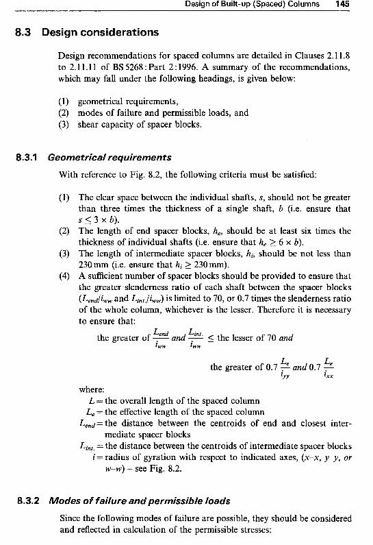
Design of Built-up (Spaced) Columns 1
Design recommendations for spaced columns are detailed in Clauses 2. l 1.8 to 2.1 1.11 of BS 5268 : Part 2 : 1996. A summary of the recommendations, which may fall under the following headings, is given below:
(1) geometrical requirements, (2) modes of failure and permissible loads, and (3) shear capacity of spacer blocks.
e o ~ e t r i c a l r e ~ u i r e ~ e ~ t s
With reference to Fig. 8.2, the following criteria must be satisfied:
The clear space between the individual shafts, S, should not be greater than three times the thickness of a single shaft, b (i.e. ensure that S 5 3 x b). The length of end spacer blocks, h,, should be at least six times the thickness of individual shafts (i.e. ensure that h, => 6 x b). The length of intermediate spacer blocks, hi, should be not less than 230 mm (i.e. ensure that hi 2 230mm). A sufficient number of spacer blocks should be provided to ensure that the greater slenderness ratio of each shaft between the spacer blocks (Lend/iww and Lint./iww) is limited to 70, or 0.7 times the slenderness ratio of the whole column, whichever is the lesser. Therefore it is necessary to ensure that:
the greater of - and - 5 the lesser of '70 and Lend Lint. l w w fww
Le Le ZYY f X X
the greater of 0.7 and 0.7
where: L = the overall length of the spaced column
L, = the effective length of the spaced column Lend= the distance between the centroids of end and closest inter-
Lint. = the distance between the centroids of intermediate spacer blocks i = radius of gyration with respect to indicated axes, (x-x, y-y, or
mediate spacer blocks
w w ) - see Fig. 8.2.
.2 des of f a i ~ ~ r e and ~ e r ~ i s s i ~ l e loads
Since the following modes of failure are possible, they should be considered and reflected in calculation of the permissible stresses:
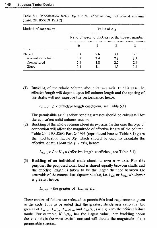
1 Structural Timber Design
able 8.1 Modi~cation factor KI3 for the effective length of spaced columns (Table 20, BS 5268 : Part 2)
Method of connection Value of K13
Ratio of space to thickness of the thinner member
0 1 2 3
Nailed Screwed or bolted Connectored Clued
1.8 2.6 3.1 3.5
1.7 2.4 2.8 3.1 1.4 1.8 2.2 2.4 1.1 1.1 1.3 1.4
(1) Buckling of the whole column about its x-x axis. In this case the effective length will depend upon full column length and the spacing of the shafts will not improve the performance, hence:
Le,X-x = L x (effective length coefficient, see Table 5.1)
The permissible axial and/or bending stresses should be calculated for the equivalent solid column section.
(2) Buckling of the whole column about its y-y axis. In this case the type of connection will affect the magnitude of effective length of the column. Table 20 of BS 5268 : Part 2 : 1996 (reproduced here as Table 8.1) gives the modification factor K13 which should be used to calculate the effective length about the y y axis, hence:
Le,y-y = L x K I 3 x (effective length coefficient, see Table 5.1)
(3) Buckling of an individual shaft about its own W-W axis. For this purpose, the proposed axial load is shared equally between shafts and the effective length is taken to be the larger distance between the centroids of the connections (spacer blocks), i.e. Lend or Lint . , whichever is greater, hence:
These modes of failure are reflected in permissible load requirements given in the code. It is to be noted that the greatest slenderness ratio (i.e. the greater of Le/ ixx , Le / iyy , Lend/iww and Lint , / iww) will govern the critical failure mode. For example, if Le/ixx has the largest value, then buckling about the x-x axis is the most critical one and will dictate the magnitude of the permissible stresses.

Design of Built-up (Spaced) Columns 147
A s before, see Section 5.2, the applied and permissible stresses may be calculated from:
P applied compressive stress oc,a,ll = 3 permissible compressive stress o c , a h , / / = CT,,~,// x K2 K3 Kg K12
M applied bending stress om,a,l l = 2 permissible bending stress om,adm,// = orn,g,/ x K2K3KbK7&
8.3.3 Shear capacity of spacer blocks
The longitudinal length of the mechanically and/or glue-connected end spacer blocks should not be less than six times the thickness of the individual shaft and should be sufficient to transmit a shear force, F,,, at the interface between each block and one shaft equal to:
1.3Aboc,u,j7 F,, = nu where:
A = total cross-sectional area of the column b = thickness of the shaft
~ ~ ~ , ~ , l l = applied compressive stress n = number of shafts, and a = distance between centres of adjacent shafts
Therefore applied shear stress, za,/, is:
where: h =width of the shaft, and h, = length of the end spacer block
Fig. 8.3 Axes in spaced columns.
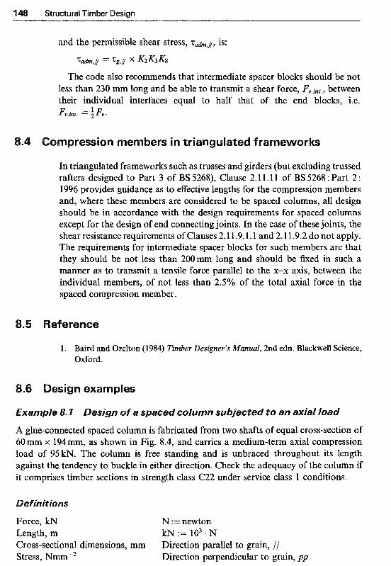
1 Structural Timber Design
and the permissible shear stress, ~ ~ c t . , ~ , is:
The code also recommends that intermediate spacer blocks should be not less than 230 mm long and be able to transmit a shear force, between their individual interfaces equal to half that of the end blocks, i.e. Fv.int. = 5 ~v
In triangulated frameworks such as trusses and girders (but excluding trussed rafters designed to Part 3 of BS 5268), Clause 2.1 1.11 of BS 5268 : Part 2 : 1996 provides guidance as to effective lengths for the compression members and, where these members are considered to be spaced columns, all design should be in accordance with the design requirements for spaced columns except for the design of end connecting joints. In the case of these joints, the shear resistance requirements of Clauses 2.1 1.9.1.1 and 2.1 1.9.2 do not apply. The requirements for intermediate spacer blocks for such members are that they should be not less than 200mm long and should be fixed in such a manner as to transmit a tensile force parallel to the x-x axis, between the individual members, of not less than 2.5% of the total axial force in the spaced compression member.
1 . Baird and Ozelton (1984) Timber Designer’s Manual, 2nd edn. Blackwell Science, Oxford.
a~ple
A glue-connected spaced column is fabricated from two shafts of equal cross-section of 60 mm x 194mm, as shown in Fig. 8.4, and carries a medium-term axial compression load of 95kN. The column is free standing and is unbraced throughout its length against the tendency to buckle in either direction. Check the adequacy of the column if it comprises timber sections in strength class C22 under service class 1 conditions.
Force, kN N :=newton Length, m kN := lo3 N Cross-sectional dimensions, mm Direction parallel to grain, // Stress, NmmW2 Direction perpendicular to grain, pp

Design of Built-up (Spaced) Columns 1
60 60 60
W i W
Cross-section
372 mm 1”
230 m 1-
230 m 1-
230 m 1”
372 m ~-
Fig. 8.4 Spaced column details (Example 8.1 ).
e~~et r j ca f r e~u j re~ents
Column length, L Number of shafts, n Breadth of each shaft, b Width of each shaft, h Space between shafts, S
Distance between centres of shafts, a
Length of end block, h, Length of intermediate block, hi Cross-sectional area of each
Total cross-sectional area, AtOtar
Second moment of area, Zxx
shaft, Ashaft
L := 3.9 m n := 2 b := 60 - mm S := 60 mm h := 184.mm
I t ~
882 m
882 m
882 m
882 m
3.9 111

150 Structural Timber Design
Second moment of area, Iyy
For each shaft, I,,
Radius of gyration, ixx
Radius of gyration, iyy
Radius of gyration, i,,
Effective length of individual shafts about their own W-W
axis is the greater of Lend
Slenderness ratio about W-W
and Lint.
axis, h,,
Effective length of column about X-X axis, Le.xx
Slenderness ratio about X-X axis
Effective length of column about y-y axis, Le,, depends on the shaft/block connections
BS5268 : Part 2, Table 20 For glued connections and for
Effective length of column about s/b ratio of 1
y-,~ axis7 L e . y y
Condition ( I ) Check: S 5 3 x b
Iyy : = & - h . ( 2 * b + ~ ) ~ - - J - * ~ * s ~ 12
Iyy = 8.61 x lo7 o mm4 I,, := & 0 h * b3 I,, = 3.31 X lo6 0 mm4
ixx = 53.12 o m
iyy :=
iyy = 62.45 o mm
i,, = 17.32 o mm Lend := 882 * mm Lint. := 882 * mm
Lend
lww h,, := -
h,, = 50.92 Le,xx := 1.0 L Le.xx = 3.9 0 m
Le.xx h, := -
hxx = 73.42 lxx
K13 := 1.1
Le.yy := 1 .O * L * K13 Le-yy = 4.29 0 m
L.YY ?Lyy := - iYY
hyy = 68.69 S = 60 o mm is less than
3. b = 180 o mm okay Condition (2) Check: he 2 6 X b h e = 372 0 mm is greater than
Condition (3) Check: hi = 230 o mm okay 6 . b = 360 o mm okay
hi 2 230mm

Design of Built-up (Spaced) Columns 151
Condition (4) Check slenderness h,, = 50.92 ratios so that the greatest 0.7 * hxx 5 l .4 h,, 5 the lesser of (70 and the 0.7 hYY = 48.09 Satisfactory greater of 0.7 h,, and 0.7 hYY)
B. Modes of failure and permissible load checks
From the above calculations it is evident that the greatest slenderness ratio, i.e. h, = 69.64, is the critical one. Therefore buckling about the x-x axis should be considered in determination of the permissible compressive stress.
2. Grade stresses
BS.5268 : Part 2, Table 7 Strength class, C22 Compression parallel to grain CT,.~,~ := 7.5 N mm-2 Shear parallel to grain "cg.[ := 0.71 N mm-2 Minimum modulus of Emin := 6500 + N * mm"2
elasticity, Emin
3. Loading and applied compressive stress
Medium-term axial loading P := 95 * kN P Applied compressive stress Gc.a.1 := -
Atotal
Uc.a.1 = 4.3 o N * mm-2
4. K-factors
Service class 1 (K2, Table 13) K2 := l Medium-term loading K3 := 1.25
No load sharing (K& Clause 2.9) K8 := 1 (K3, Table 14)
Modification factor for the compression member, can be calculated using either one of the following methods:
(1) Using equation in Annex B:
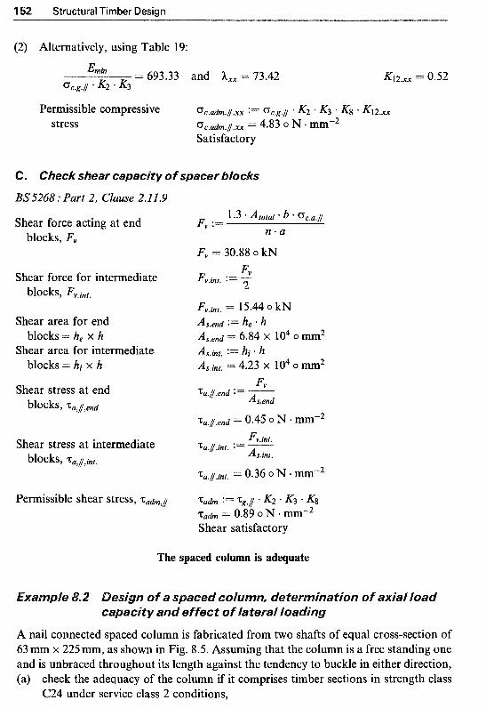
1 Structural Timber Design
(2) Alternatively, using Table 19:
4nin
%.g.// * K2 ' K3 = 693.33 and hxx = 73.42
Permissible compressive ~ c . a d m . / / . x x := Gc.g.// K2 * K3 ' K8 * K12.x~ stress U c . a h . i . x x = 4.83 o N * mmv2
Satisfactory
s~ear capacity of spacer ~ l ~ c k s
BS.5268 : Part 2, Clause 2.11.9
Shear force acting at end blocks, F,,
F,, = 30.88 o kN
Permissible shear stress, zah , i z a h := 1cs.1 K2 K3 Kg z a h = 0.89 o N mmm2 Shear satisfactory
The s ~ a c e ~ column is a ~ e ~ u a t e
fa an
A nail connected spaced column is fabricated from two shafts of equal cross-section of 63 mm x 225 mm, as shown in Fig. 8.5. Assuming that the column is a free standing one and is unbraced throughout its length against the tendency to buckle in either direction, (a) check the adequacy of the column if it comprises timber sections in strength class
C24 under service class 2 conditions,
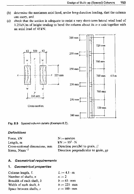
Design of Built-up (Spaced) Columns 115
(b) determine the maximum axial load, under long-duration loading, that the column can carry, and
(c) check that the section is adequate to resist a very short-term lateral wind load of 1.25 kN/m of height tending to bend the column about its x-x axis together with an axial load of 45 H?.
! ! w i b
Cross-section
Spaced column details (Example 8.2).
Force, kN Length, m
N :=newton k~ := 103 . N
Cross-sectional dimensions, mm Direction parallel to grain, // Stress, Nmrn-2 Direction perpendicular to grain, pp
Column length, L L := 4.1 + m Number of shafts, n n : = 2 Breadth of each shaft, b b := 63 mm Width of each shaft, h h := 225 mm Space between shafts, S S := 100. mm
4.1 m

154. Structural Timber Design
Distance between centres of shafts, a
Length of end block, he Length of intermediate block, hi Cross-sectional area of each
Total cross-sectional area, Atotal shaft, Ashaft
Second moment of area, Ixx
Second moment of area, Iyy
For each shaft, I,,
Radius of gyration, ixx
Radius of gyration, iyy
Radius of gyration, iww
Effective length of individual shafts about their own minor W-W axis is the greater of Lend and Lint.
Slenderness ratio about W-W
axis, h,,
Effective length of column about x-x axis, Le,,,
Slenderness ratio about x-x axis
Effective length of column about p" axis, Le.yy, depends on the shaft/block connections
BS5268 : Part 2, Table 20 For nailed connections and for
s/b ratio of 1.59
a = 163 o m he := 380 * mm hi := 250. mm Ashaft := b * h Ashaft = 1.42 X io4 o mm2 Atotal := 2 Ashaft Atotal = 2.84 X lo4 o mm2 Ixx := (2) * g - b * h3
Iyy : = g . h * ( 2 . b + ~ ) 3 - - i l i . h . s 3 rXx = 1.2 X io8 0mm4
Iyy = 1.98 x 10' o mm4
I,, = 4.69 x lo6 o mm4 Iww :=A* h * b3
ixx = 64.95 o mm
iyy = 83.5 o mm 7
i,, = 18.19 omm Lend := 720 mm Lint. := 760 mm
Lint. h,, := - Lww
h,, = 41.79 Le.xx := 1 .O * L Le.xx = 4. l 0 m
L x x h, := -
h, = 63.12 lxx

Design of Built-up (Spaced) Columns 155
Effective length o f column about Le.yy := 1 .O L K13 Y-Y axis, Le.yy Le.yy = 11.87 o m
Slenderness ratio about y-y axis: hyy := - Le.YY
ZYY hyy = 142.14
Condition ( I ) Check: S 5 3 x b S = 100 o mm is less than 3 - b = 189 o mm okay
Condition (2) Check: he 2 6 X b he = 380 o mm is greater than 6 . b = 378 o mm okay
Condition (3) Check: hi 2 230mm hi = 250 o mm okay Condition (4) Check slenderness h,, = 41.79
ratios so that the greatest 0.7 h, = 44.19 h,, 5 the lesser of (70 and the 0.7 - hyy = 99.5 Satisfactory greater of 0.7 h,, and 0.7 hyy)
B. Modes of failure and permissible load checks
From the above calculations it is evident that the greatest slenderness ratio, i.e. hyy = 142.14, is the critical one. Therefore buckling about the y-y axis should be considered in determination o f the permissible compressive stress.
2. Grade stresses
BS 5268 : Part 2, Table 7 Strength class, C24 Compression parallel to grain cT,.g.l := 7.9 e N . mm-2 Shear parallel to grain zg.i := 0.71 N mm-2 Bending parallel to grain c ~ ~ . ~ . j := 7.5 N mm-2 Minimum modulus o f Emin := 7200 N mm-2
elasticity, Emin
3. K-factors
Service class 2 (K2, Table 13) K2 := 1 Long-term loading K3.iong := 1
Very short-term loading K3.v.short := 1-75
No load sharing (Kg, Clause 2.9) K8 := 1
(K3, Table 14)
(K3, Table 14)
Modification factor for the compression member, K12, can be calculated using either one o f the following methods:

Structural Timber Design
Alternatively, using Table 19:
= 911.39 and hyy = 142.14 Gc.g.1 K2 * K3.1ong
Permissible compressive G c . a h . 1 := Gc.g.// * K2 ' K3.long * K8 * K12.y~
Allowable axial compressive Pa& := Gc.ah,// . Atotal
Applied compressive stress Gc.a,// := Gc.ah.//
stress ~ ~ . ~ h . [ = 1.840 N.mm"2
load, Padm Pa& = 52.14 o kN
= 1.84 o N a mm-2
BS5268 : Part 2, Clause 2.1 l .9
Shear force acting at end blocks, E;
Shear force for intermediate blocks, Fv.int.
Shear area for end blocks
Shear area for intermediate blocks
Shear stress at end blocks, Ta,flend
Shear stress at intermediate blocks, Ta,//,int.
Permissible shear stress, TU&,/
The axial loa~-carryin~ capacity of the spaced column is P a h = 52.14 o
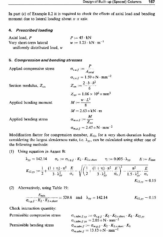
Design of Built-up (Spaced) Columns l
In part (c) of Example 8.2 it is required to check the effects of axial load and bending moment due to lateral loading about x-x axis:
Axial load, P Very short-term lateral
uniformly distributed load, W
P := 45 kN W := l .25 kN - m-1
P Applied compressive stress %a./ := ___ &tal
~ ~ . ~ . i = 1.59 O N *mm"2
Section modulus, Zxx 2 * b * h 2
Zxx := - 6 Zxx = 1.06 x lo6 o mm3
W * L2 Applied bending moment M := - 8
M = 2.63 o kN m M Applied bending stress 0 m . a . i ;== -
Z x x
Gm.a.1 = 2.47 o N mm-2
Modification factor for compression member, K12, for a very s~ort-duration loading considering the largest slenderness ratio, i.e. hyy, can be calculated using either one of the following methods: (1) Using equation in Annex B:
(2) Alternatively, using Table 19:
Emin
Gc.g.1 K2 * K3.v.short = 520.8 and hyy = 142.14 K12.yy = 0.15
Check interaction quantity: Permissible compressive stress ocs~. i ,yy := oc.g~l K2 - K3.v.short + Kg K12.yy
Permissible bending stress om.aa'm.1 := Gm.g.1 * K2 . K3.v.short * K8 c~~.~h.1.~~ = 2.05 o N mmp2
om.adm.i = 13.13 o N mmm2

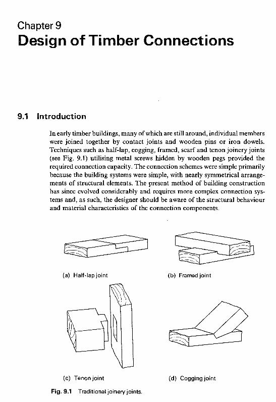
Chapter 9 0 ber Conn
In early timber buildings, many of which are still around, individual members were joined together by contact joints and wooden pins or iron dowels. Techniques such as half-lap, cogging, framed, scarf and tenon joinery joints (see Fig. 9.1) utilising metal screws hidden by wooden pegs provided the required connection capacity. The connection schemes were simple primarily because the building systems were simple, with nearly symmetrical arrange- ments of structural elements. The present method of building construction has since evolved considerably and requires more complex connection sys- tems and, as such, the designer should be aware of the structural behaviour and material characteristics of the connection components.
(a) Half-lap joint (b) Framed joint
(c) Tenon joint
Fig. 9.1 Traditional joinery joints.
(d) Cogging joint
159

1 Structural Timber Design
he common connecting systems in str tural timber may be classified as mechanically fastened and glued joints. chanical fasteners may also be divided into two groups depending on h hey transfer the forces between the connected members. These being ~ o ~ e ~ - t y ~ ~ fasteners, such as nails, screws, bolts and dowels, and connectors, such as toothed-plates, split-rings, shear plates and punched metal plates in which the load transmission is
arily achieved by a large bearing area at the surface of the members. n this chapter details of the general considerations necessary for the
design of dowel-type fasteners are described. This is followed by details of the recommendations for the design of connectored and glued timber joints.
As mentioned in Chapter 2, the most recent revision of Part 1996 was to bring this code as close as possible and to run
E m 1995-1-1 Eurocode 5: Design of t i ~ b e r structures. Part l .l ~ e ~ e r a l rules and rules for buiZdings (EC5). The overall aim has been to incorporate material specifi~ations and design approaches from EC5, while maintaining a
issible stress code which designers, accustomed to iar with and be able to use without difficulty. In t
gy for dowel-type connections has been subjected to considerable ge and while it remains a permissible stress design method, it takes the approach to design of nailed, screwed, bolted and dowelled connections.
commendations for timber joints are detailed in Section 6 of t 2. This section provides the basic lateral shear and withdrawal e most common dowel type fasteners in Tables 54-74. The
les have been calculated using the equations and summary of €365 rules and equations is given in
ese equations can be used in lieu of the tabulate^ data if preferred, and may be used for other material/fastener applications that are not currently detailed in the code, for example, the use of bronze or copper and high tensile steel dowels. n this chapter design
lations are based on the tabulated values; while the use of e ~ u a t i o ~ s is scussed in Chapter 10 which outlines the Eurocode approach to design of
A summary of the general design considerations for timber joints detailed timber structures.
in Section 6 of the code is as follows:
(1) Joints should be designed so that the loads induced in each fastener or timber connector unit by the design loads appropriate to the structure should not exceed the permissible values determined in accordance with Section 6 of the code.
(2) When more than one nail, screw, bolt, etc. is used in a joint, the permissible load is the sum of the permissible loads for the individual

Design of Timber Connections 1
F
U .2 Shear stress in the jointed timber.
units providing that the centroid of the fasteners' group lies on the axis of the member, and that the spacing, edge and end distances are sufficient to develop the full strength of each fixing unit. If the line of action of a force in a member does not pass through the centroid of the fasteners' group, account should be taken of the stresses and rotation due to the secondary moments induced by the eccentric- ity. This will impose higher loads on the fasteners furthest from the centroid of the group. If the load on a joint is carried by more than one type of fastener, due account should be taken of the relative stiffnesses. Clue and mechani- cal fasteners have very different stiffness properties and should not be assumed to act in unison. F& the purpose of designing joints in glued laminated timber, tabulate values should be taken for the strength class of timber from which the glued laminated timber was made. The effective cross-section of a jointed member should be used when calculating its strength. In addition, the shear stress condition shown in Fig. 9.2 should be satisfied in the jointed member. Therefore the design requirement is to ensure that:
Y < $ . T U & ' h , . t (9.1) where:
Y = maximum shear force per member at the joint where
h, =distance from the loaded edge to the furthest fastener (Yl + Y2 = Fsina)
= permissible shear stress, and t =member thickness.
int sli
All mechanically connected timber joints, under the action of applied load, will undergo slip which occurs between their component parts. Slip can be a
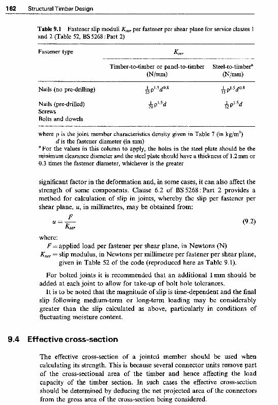
162 Structural Timber Design
Table 9.1 Fastener slip moduli Kser per fastener per shear plane for service classes 1 and 2 (Table 52, BS 5268 :Part 2)
Fastener type Kser
Timber-to-timber or panel-to-timber Steel-to-timbera (N/mm) (N/mm)
Nails (no pre-drilling) & p'-5d0-8 h p'.5d0.8
Nails (pre-drilled) Screws Bolts and dowels
p'v5d
where p is the joint member characteristics density given in Table 7 (in kg/m3)
a For the values in this column to apply, the holes in the steel plate should be the minimum clearance diameter and the steel plate should have a thickness of l .2 mm or 0.3 times the fastener diameter, whichever is the greater
d is the fastener diameter (in m)
significant factor in the deformation and, in some cases, it can also affect the strength of some components. Clause 6.2 of BS5268: Part 2 provides a method for calculation of slip in joints, whereby the slip per fastener per shear plane, U, in millimetres, may be obtained from:
F &er
U=-
where:
Kser = slip modulus, in Newtons per millimetre per fastener per shear plane, given in Table 52 of the code (reproduced here as Table 9.1).
F = applied load per fastener per shear plane, in Newtons (N)
For bolted joints it is recommended that an additional 1 mm should be added at each joint to allow for take-up of bolt hole tolerances.
It is to be noted that the magnitude of slip is time-dependent and the final slip following medium-term or long-term loading may be considerably greater than the slip calculated as above, particularly in conditions of fluctuating moisture content.
ective cross-section
The effective cross-section of a jointed member should be used when calculating its strength. This is because several connector units remove part of the cross-sectional area of the timber and hence affecting the load capacity of the timber section. In such cases the effective cross-section should be determined by deducing the net projected area of the connectors from the gross area of the cross-section being considered.

Design of Timber Connections 163
The recommendations of BS 5268 : Part 2 for multi-dowel-type joints are as follow:
(1) Nailed and screwed joints. When assessing the effective cross-section of multi-nailed or multi-screwed joints, all nails or screws of 5 mm in diameter, or larger, that lie within a distance of five nail or screw diameters, measured parallel to the grain from a given cross-section, should be considered as occurring at that cross-section.
No reduction of cross-section needs to be made for screws of less than 5mm diameter, and for nails of the same diameter but driven without pre-drilling.
(2) Bolted and dowelled~oints. When assessing the effective cross-section of multi-bolted or multi-dowelled joints, all bolts or dowels that lie within a distance of two bolt or dowel diameters, measured parallel to the grain from a given cross-section, should be considered as occurring at that cross-section.
(3) Connectored joints. When assessing the effective cross-section of multi- connectored joints, such as toothed-plate, split-ring and shear-plate con- nector joints, all connectors and their bolts that lie within a distance of 0.75 times the nominal size of the connector measured parallel to the grain from a given cross-section should be considered as occurring at that cross-section.
9.5 Spacing rules
In order to avoid splitting of timber, all dowel-type fasteners must be spaced at suitable distances from each other and from the ends and edges of timber or wood-based material. The various distances involved are illustrated in Fig. 9.3.
An end distance is said to be loaded when the load on the fastener has a component towards the end of the timber. Otherwise, it is referred to as an unloaded end distance. Loaded end distances need to be greater than unloaded ones. In a similar way the edge distance may be loaded or unloaded. 92
Fig. 9.3 Spacing of dowel-type connectors.

l Structural Timber Design
The values of spacings and distances vary from one fastener type to another, as well as between the various material types. The spacings and distances recommended in Section 6 of BS 5268 : Part 2 are detailed below:
Nail spacing. The recommended end and edge distances and spacing of nails, to avoid undue splitting, are given in Table 53 of the code (reproduced here as Table 9.2).
Pre-drilling (with a hole diameter up to 0.8 times the nail diameter) reduces the splitting tendency considerably and hence allows much closer spacing of the nails.
All softwoods, except Douglas fir, may have values of spacing (but not edge distances) for timber to timber joints multiplied by 0.8. For nails driven into a glued laminated section at right angles to the glue surface, the spacings (but not edge distances) can be multiplied by a further factor of 0.9. Screw spacing. The recommended end and edge distances and spacing of screws, to avoid undue splitting, are given in Table 59 of the code (reproduced here as Table 9.3). Bolt and dowel spacings. The recommended end and edge distances and spacing of bolts and dowels are given in Table 75 of the code (reproduced here as Table 9.4).
able 9.2 Minimum nail spacings (Table 53, BS 5268 : Part 2)
Spacing" Timber-to-timber joints Steel plate-to- Wood-based timber joints panel productsb
to-timber joints
Without With Without Without pre-drilled pre-drilled pre-drilled pre-drilled
holes holes holes holes
End distance parallel to 20d 10d 14d 14d
Edge distance perpendicular 5d Sd 5d c
Distance between lines of 10d 3d 7d 7d
grain (Q)
to grain (a4)
nails, perpendicular to grain (a2)
nails in any one line, parallel to grain (al)
Distance between adjacent 20d 1 Od 14d 14d
where d is the nail diameter aSpacings and distances are illustrated in Fig. 9.3
Plywood, tempered hardboard or particleboard c The loaded edge distance should not be less than: in timber 5d, in plywood 3d, in particleboard and tempered hardboard 6d, and in all other cases the edge distance should not be less than 3d
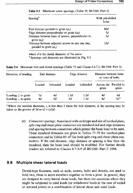
Desian of Timber Connections 165
Table 9.3 Minimum screw spacings, (Table 59, BS 5268 :Part 2)
Spacinga With pre-drilled holes
End distance parallel to grain (a3) 10d Edge distance perpendicular to grain (a4) 5d Distance between lines of screws, perpendicular to 3d
Distance between adjacent screws in any one line, 10d grain (az)
parallel to grain (a,)
where d is the shank diameter of the screw "Spacings and distances are illustrated In Fig. 9.3
Table 9.4 Minimum bolt and dowel spacings (Table 75 and Clause 6.6.7.3, BS 5268 : Part 2)
Direction of loading End distance Edge distance Distance between bolts or rows of bolts
Loaded Unloaded Loaded Unloaded Across the Parallel to grain grain
Loading // to grain 7d 4d 1.5d 1.5d 4d 4d Loading L to grain 4d 4d 4d 1.5d 4d 5d a
aWhere the member thickness, t, is less than 3 times the bolt diameter, d, the spacing may be taken as the greater of 3d or (2 + t/d)d.
(4) Connectors spacings. Associated with each type and size of toothed-p~ate, split-ring and shear-plate connectors are standard end and edge distances and spacing between connectors which permit the basic load to be used. These standard distances are given in Tables 77-79 for toothed-plate connectors and in Tables 85-87 for both split-ring and shear-plate con- nectors. If the end distance, edge distance or spacing is less than the standard, then the basic load should be modified. For further details readers are referred to Clauses 6.7-6.9 of BS 5268 : Part 2 : 1996.
shear lateral loads
Dowel-type fasteners, such as nails, screws, bolts and dowels, are used to hold two, three or more members together to form a joint. In general, they are designed to carry lateral shear loads, but there are occasions where they might be subjected to axial loads (or withdrawal loads in the case of nailed or screwed joints) or a combination of lateral shear and axial loads.

4 66 Structural Timber Design
I F
4
l F/2 I F/2 f i" i"
+ / F IF
(a) ( b) (c)
Fig. 9.4 Single shear (a) and (b) and double shear (c) joints.
Dowel-type fasteners, depending on their type and size and the arrange- ment of the joint components, may be subjected to single, double or multiple lateral shear forces (see Fig. 9.4). It is important to note that the dowels in joints (a) and (b), shown in Fig. 9.4, are all in single shear (i.e. one shear plane per dowel) and the dowels in joint (c) are in double shear (i.e. two shear planes per dowel).
The basic multiple shear lateral load for each dowel can generally be obtained by multiplying the value for its basic single shear load (given in the relevant tables of the code) by the number of shear planes; provided that the recommended standard thickness for members of the joint and the recom- mended joint details are met.
9.7 Nailed joints
Nails are straight slender fasteners, usually pointed and headed, and are available in a variety of lengths and cross-sectional areas. There are also many types and forms of nails; but the most frequently used nails are the bright, smooth, common steel wire nails with circular cross-sectional area with a minimum tensile strength of 600N/mm2, which are available in standard sizes of 2.65 mm to 8mm in diameter. Nails can be plain or enamelled, etched, electroplated, galvanised or polymer coated, for example, for protection against corrosion.
Nailed joints, which should normally contain at least two nails, are simple to fabricate and are of considerable economic value. They are suitable for lightly loaded structures and for thin members. They are commonly used in framing, walls, decks, floors and roofs and in nearly every construction that involves light loads and simple elements. For the outer (headside) members larger than 50mm thick, nails are generally replaced by bolts to reduce splitting of the timber.

Design of Timber Connections 167
The performance of a nail, both under lateral and withdrawal loading, may be enhanced by mechanically deforming nail shanks to form annular ringed shank or helical threaded shank nails (see Fig. 9.5). Such nails provide higher withdrawal resistance than plain shank nails of the same size. Other forms of improved nails are obtained by grooving or twisting of square cross- sectioned nails. The process of twisting not only modifies the nail surface but also work-hardens the steel, increasing its yield strength.
In order to provide for the enhanced performance of improved nails, I3S 5268 :Part 2, Clause 6.4.4.4 permits a 20% increase in the basic single shear lateral load capacities of the square grooved and square twisted shank nails, and a 50% increase in the basic withdrawal load capacities for the threaded part of annular ringed shank and helical threaded shank nails.
Nails driven into dense timbers are likely to induce timber splitting. Various research studies have shown that pre-drilling can prevent timber splitting and also has other advantages of less slip in the joint, increase in lateral load-carrying capacity and permits a more densely nailed joint (i.e. reduced nail spacings and distances).
The recommendations of BS 5268 : Part 2 for pre-drilling are as follows:
(1) Hardwoods in strength classes of D30 to D70 will usually require pre- drilling and the code recommends that the diameter of pre-drilled holes should not be greater than 0.8 times the nail diameter.
In general it is usual to provide pre-drilling when the density of the timber is 500 kg/m3 or greater.
(2) For nails driven into pre-drilled holes in softwood strength classes C14 to C40 and TR26, the code permits a 15% increase in their load capacities.
3
(a) Round wire (b) Annular ringed (c) Helical threaded
Fig. 9.5 Types of nails.

1 Structural
Tim
ber D
esign
m
3 5 S o! 52
U
0
m
3 9
o! 52
4 0
h0 E

Design of Timber Connections 16
1. T i ~ ~ e r - t o - t i ~ ~ e r nailed joints The basic single shear lateral loads for single round wire nails with a ~ n i m u m tensile strength of 600N/mm2, driven at right angles to the side grain of timber in service classes l and 2, are given in Table 54 of the code (reproduced here as Table 9.5).
For nails driven into the end grain of timber, the values given in Table 54 should be multiplied by the end grain modification factor K 4 3 which has a value of 0.7, i.e. K43 = 0.7.
For nails driven into pre-drilled holes in softwood strength classes C14 to C40 and TR26, the basic single shear lateral load values given in Table 54 may be multiplied by 1.15, i.e. for convenience introduce a modification factor for pre-drilling, as Kpre-dr$/ = 1.15.
For square grooved and square twisted shank nails of steel with a yield stress of not less than 375 N/mm2, the basic single shear lateral loads given in Table 54 should be multiplied by the improved nail lateral modification
which has a value 1.2, i.e. KM = 1.2. asic loads in Table 54 to apply, the nails should fully penetrate
the tabulated standard values in both the headside and pointside members. n addition, for joints where nails are subjected to multiple shear lateral
loads, the thickness of the inner member should be at least 0.85 times the standard thickness given in Table 54. Otherwise, the basic shear load should be multiplied by the smaller of the following ratios, where relevant:
(1) actual to standard thickness of headside member, or (2) actual penetration to standard pointside thickness, or (3) actual inner member to 0.85 times the standard thickness.
is important to note that no load-carry in^ capacity should be assumed here the ratios given above are less than 0.66 for softwoods and 1.0 for
here improved nails are used, t ratios may be reduced to 0.50 for softwoods and 0.75 for hardwood addition no increase in basic load is permitted for thicknesses or pe ations greater than the standard values.
erefore, with reference to Fig. 9.6, it is possible to define a modification factor for thickness of members and penetration depth (i.e. bearing lengths) for a nailed connection, &ai&bearing, as: for a nail in single shear,
for a nail in multiple shear,

170 Structural Timber Design
F +"--- la , head
fa, point ..--"F
Nails driven into side grain
ta, head
F . (a) Nails in single shear
Nails
head
inner
poir1t
"--+=+ F/2
-W F/2
Fig. 9.6 Member thicknesses in nailed joints.
2. Steel plate-to-timber nailed joints Steel plate-to-timber nailed joints can have a considerably higher load capacity than timber-to-timber joints with similar nailing arrangements. BS 5268 :Part 2, Clause 6.4.5 recommends a 25% higher load capacity for steel plate-to-timber joints provided that steel plates have a minimum thickness equal to the greater of 1.2mm or 0.3 times the nail diameter.
Where a pre-drilled steel plate or component of such thickness is nailed to a timber member, the basic single shear lateral load given in Table 54 should be multiplied by the steel-to-timber modification factor, K44, which has a value of 1.25, i.e. K 4 6 = 1.25.
It is recommended that the diameter of the hole in the steel plate should not be greater than the diameter of the nail.
3. ~lywood-to-timber nailed joints The basic single shear lateral loads for single nails in a plywood-to-timber joint, where the nails are driven through the plywood at right angles into the side grain of timber in service classes 1 and 2, are given in Table 56 of the code (reproduced here as Table 9.6).
For the basic loads in Table 56 of the code to apply, the plywood should be selected from those given in Section 4 of the code, and the nails should be fully embedded and should have an overall length not less than those tabulated.
4. Tempered hardboard-to-timber nailed joints The basic single shear lateral loads for single nails in a tempered hardboard- to-timber joint, where the nails are driven through the tempered hardboard

Table 9.6 Basic single shear lateral loads for round wire nails in a plywood-to-timber joint, (Table 56, BS 5268 :Part 2)
Plywood Nail Basic single shear lateral load, (N) .~ __ ~-
Nominal Diameter Length Strength class thickness (mm) (mm) (mm) Softwoods (not pre-drilled) Hardwoods (pre-drilled)
C14 C16/18/22 C24 C27/30/35/40 D30/35/40 D50/60/70
Plywood groupa Plywood groupa
I I1 I I1 I I1 I I1 I I1 I I1
6
9
12
15
18
21
29
2.65 3 .OO 3.35 3.75 4.00
2.65 3 .OO 3.35 3.75 4.00 2.65 3.00 3.35 3.75 4.00 2.65 3 .OO 3.35 3.75 4.00 2.65 3.00 3.35 3.75 4.00 2.65 3 .OO 3.35 3.75 4.00 2.65 3 .OO 3.35 3.75 4.00
40 50 50 75 75
40 50 50 75
175 45 50 50 75 75 50 65 65 75 75 50 65 65 75 75 50 65 65 75 75 50 65 65 75 75
207 252 30 1 344 360
218 26 l 308 366 405 240 28 1 320 383 42 l 266 308 353 408 445 272 339 384 439 476 275 352 41 1 474 510 233 352 403 509 552
216 262 311 373 414
230 280 328 387 427 256 306 336 410 449
285 337 383 440 478 292 361 417 474 51 1 280 360 432 513 55 1 235 3 56 407 515 572
212 258 308 344 360 223 267 315 374 414 244 287 334 391 430 27 1 314 360 416 454 283 345 391 447 485 288 360 426 483 520 242 360 423 521 573
22 l 268 319 382 424 24 1 286 335 396 436 268 312 353 419 459 298 343 39 1 449 488 30 1 369 425 483 522 2C3 369 443 523 562 245 365 426 527 586
220 268 318 344 360 23 1 277 327 389 430 253 297 345 406 446
280 324 372 43 1 470 305 356 404 462 501 306 375 440 499 537 26 1 375 450 542 603
230 279 332 399 438 250 297 348 412 454 278 324 374 435 477 310 356 405 466 506 314 386 440 500 540 314 385 462 54 1 58 1
263 380 456 550 61 1
224 273 318 344 360 235 28 1 332 395 438 256 302 351 412 453 284 329 378 438 477
31 1 361 410 469 509 31 1 382 446 506 545 270 382 458 552 614
234 284 339 407 438 255 302 355 419 463 282 329 380 443 485 314 36 1 412 473 515 320 393 446 508 549 320 393 47 1 549 590 273 388 465 560 623
267 295 318 344 360
274 333 397 479 518 297 353 41 5 492 545 327 382 442 518 568
361 417 477 552 60 1 372 456 517 59 1 64 1 372 46 1 557 675 754
28 1 346 387 419 438
301 362 429 514 57 1 330 389 454 535 590
365 424 487 566 619 388 46 1 525 603 655 387 479 570 649 70 1 380 470 568 690 770
270 295 318 344 360 286 347 415 495 518 309 367 432 513 567 339 397 459 538 59 1
374 432 495 572 623 39 1 472 535 612 664 39 1 483 583 707 789
296 358 387 419 438 315 379 450 539 599 345 406 474 559 616 3 80 4 4 1 508 590 645
409 479 546 627 68 1 408 504 592 674 727 399 494 597 723 808
aPlywood group I comprises: (a) American construction and industrial plywood (b) Canadian Douglas fir plywood (c) Canadian softwood plywood (d) Finnish conifer plywood (e) Swedish softwood plywood Plywood group I1 comprises: (a) Finnish birch-faced plywood (b) Finnish birch plywood
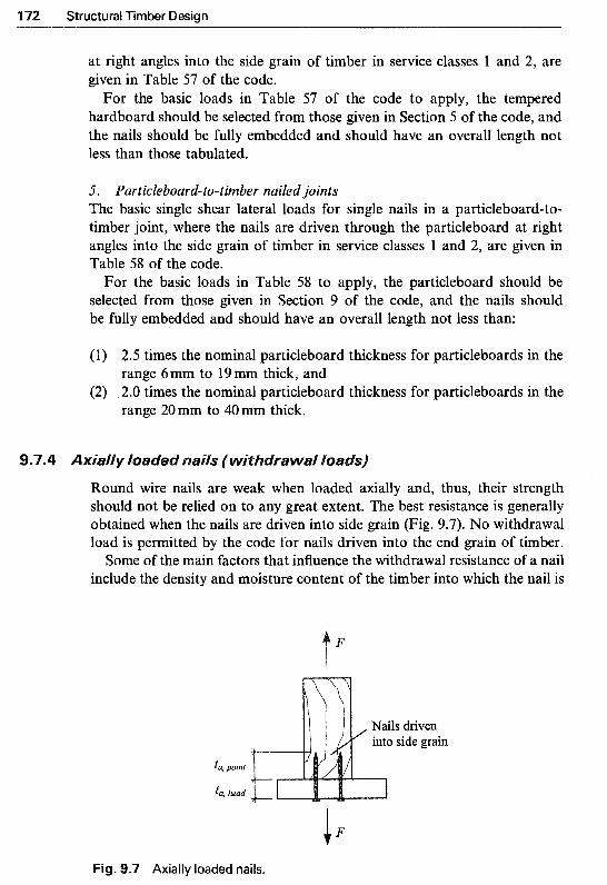
72 Structural Timber Design
at right angles into the side grain of timber in service classes 1 and 2, are given in Table 57 of the code.
For the basic loads in Table 57 of the code to apply, the tempered hardboard should be selected from those given in Section 5 of the code, and the nails should be fully embedded and should have an overall length not less than those tabulated.
5. ~arti~leboard-to-ti~ber nailed joints The basic single shear lateral loads for single nails in a particleboard-to- timber joint, where the nails are driven through the particleboard at right angles into the side grain of timber in service classes 1 and 2, are given in Table 58 of the code.
For the basic loads in Table 58 to apply, the particleboard should be selected from those given in Section 9 of the code, and the nails should be fully embedded and should have an overall length not less than:
(1) 2.5 times the nominal particleboard thickness for particleboards in the
(2) .2.0 times the nominal particleboard thickness for particleboards in the range 6 mm to 19 mm thick, and
range 20mm to 40mm thick.
Round wire nails are weak when loaded axially and, thus, their strength should not be relied on to any great extent. The best resistance is generally obtained when the nails are driven into side grain (Fig. 9.7). No withdrawal load is permitted by the code for nails driven into the end grain of timber.
Some of the main factors that influence the withdrawal resistance of a nail include the density and moisture content of the timber into which the nail is
F
ta, point
fa, head F Fig. 9.7 Axially loaded nails.

Design of Timber Connections 173
able 9.7 Basic withdrawal loads per millimetre of pointside penetration for smooth round wire nails driven at right angles to the grain (Table 55, BS 5268 :Part 2)
Nail Basic withdrawal loada, (N/mrn) diameter (mm.) Strength class
C 14 C 161 18/22 C24 C27/30/35/40 D30/35/40 D50/60/70
2.65 3 .OO 3.35 3.75 4.00 4.50 5 .OO 5 -60 6.00 6.70 8 .OO
1.28 1.45 1.62 1.81 1.93 2.17 2.41 2.70 2.90 3.23 3.86
1 SO 1.69 l .B9 2.12 2.26 2.54 2.82 3.16 3.39 3.78 4.5 1
1.99 2.25 2.52 2.82 3 .OO 3.38 3.76 4.21 4.5 1 5.03 6.01
2.42 2.74 3.06 3.42 3.65 4.1 1 4.56 5.1 1 5.48 6.12 7.30
5.86 6.64 7.41 8.30 8.85 9.96
1 1.06 12.39 13.28 14.82 17.70
9.80 1 1.09 12.39 13.87 14.79 16.64 18.49 20.71 22.19 24.78 29.58
a The pointside penetration of the nail should not be less than 15 mm
driven and the nail type. As mentioned earlier, the type and surface con- dition of nails enhances their performance, for example, cement or polymer coated, annular ringed shank and helical threaded shank and square twisted nails all perform better under withdrawal loading than round wire nails. In addition such improved nails are less affected by changes in the moisture content of the timber.
The basic withdrawal loads for single nails driven at right angles to the side of timber in service classes 1 and 2 are given in Table 55 of the code (reproduced here as Table 9.7). "he values apply to each 1 mm depth of actual pointside penetration achieved; where the pointside penetration of the nail should not be less than 15 mm.
For the threaded part of annular ringed shank and helical threaded shank nails, BS 5268 : Part 2 recommends that the basic withdrawal loads given in Table 55 should be multiplied by the improved nail withdrawal modification factor, &S, which has a value of 1.5, i.e. &S = 1 S .
Clause 6.4.9 of BS 5268 : Part 2 states that the permissible load for a nailed joint should be determined as the sum of the permissible loads for each nail in the joint, where each permissible nail load, FUh, should be calculated from the equation:
~ u h = F x &8&9KSO (9.3)
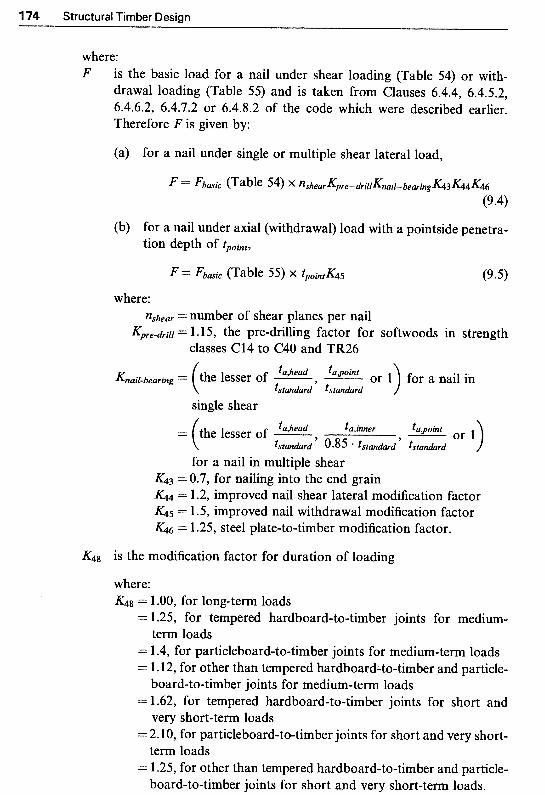
174 Structural Timber Design
where: F is the basic load for a nail under shear loading (Table 54) or with-
drawal loading (Table 55) and is taken from Clauses 6.4.4, 6.4.5.2, 6.4.6.2, 6.4.7.2 or 6.4.8.2 of the code which were described earlier. Therefore F is given by:
(a) for a nail under single or multiple shear lateral load,
(b) for a nail under axial (withdrawal) load with a pointside penetra- tion depth of tpoint,
where: nshear = number of shear planes per nail
K&e-drilf= 1.15, the pre-drilling factor for softwoods in strength classes C14 to C40 and TR26
single shear
= (the lesser of - ta,head ta,inner l a p i n t or 1)
= 0.7, for nailing into the end grain
tstanhrd ’ 0.85 * tstandard ’ tstandard
for a nail in multiple shear
K& = 1.2, improved nail shear lateral modification factor &S = 1.5, improved nail withdrawal modification factor = 1.25, steel plate-to-timber modification factor.
K4, is the modification factor for duration of loading
where: K4, = 1.00, for long-term loads = 1.25, for tempered hardboard-to-timber joints for medium-
= 1.4, for particleboard-to-timber joints for medium-term loads = 1.12, for other than tempered hardboard-to-timber and particle-
= 1.62, for tempered hardboard-to-timber joints for short and
= 2.10, for particleboard-to-timber joints for short and very short-
= l .25, for other than tempered hardboard-to-timber and particle-
term loads
board-to-timber joints for medium-term loads
very short-term loads
term loads
board-to-timber joints for short and very short-term loads.

Design of Timber Connections 175
1yQ9 is the modification factor for moisture content
where: &9 = 1.00, for lateral loads in joints in service classes 1 and 2 = 0.70, for lateral loads in timber-to-timber joints in service class 3 = 1.00, for lateral loads using annular ringed shank nails and
= 1.00, for withdrawal load in all constant service class conditions =0.25, for withdrawal loads where cyclic changes in moisture
helical threaded shank nails in all service class conditions
content can occur after nailing.
K50 is the modification factor for the number of nails of the same diameter in each line, acting in shear, for an axially loaded member, loaded parallel to the line of nails
where: K50 = 1 .OO, for the number of nails in each line < 10 = 0.9, for the number of nails in each line 2 10 = 1.00, for all other loading cases.
9.8 Screwed joints
Wood screws are used in place of nails in applications requiring higher capacities, in particular in situations where a greater resistance to withdrawal is required. In general withdrawal resistance of screws is 2 to 3 times that of nails of a similar size. They can be used for timber-to-timber joints but they are especially suitable for steel-to-timber and panel-to-timber joints.
Screws should always be inserted by threading into pre-drilled holes in the timber using a screwdriver and not hammered, and the basic values given in the code are based on this assumption. Otherwise the load-carrying capacity, mainly the withdrawal resistance, will decrease significantly. The hole for the shank should have a diameter equal to the shank diameter and should have the same length as the shank. The pilot hole for the threaded portion of the screw should have a diameter of about half the shank diameter.
The most common types of wood screws are the countersunk head, round head and coach screws. These are illustrated in Fig. 9.8.
The design recommendations given in BS 5268 : Part 2, Clause 6.5 apply to steel screws which conform to BS 1210 : 1963. The diameter relates to the smooth shank, which ranges from 3.45-7.72 mm for countersunk and round headed screws. Coach screws, in general, range frkm 6-2Omm in shank diameter.
Coach screws, with nut-like head, require a washer and should always be threaded into pre-drilled holes. They are available in lengths of 25-300 mm and are most suitable in large connections to hold timber connectors such as dowels in place or in situations where the use of bolts is not suitable due to one-sided access.

Structural Timber Design
(a) Countersunk head (b) Round head (c) Coach
Common types of wood screws.
s ~ ~ a r lat~ral ~ o a ~ s
1. ~imber-to-timber screwed joints The basic single shear lateral loads for single screws with a minimum tensile strength of 550 N/mm2, threaded at right angles to the side grain of timber in service classes 1 and 2, are given in Table 60 of the code (reproduced here as Table 9.8).
For screws inserted into the end grain of timber, the values given in Table 60 should be multiplied by the end grain modification factor, K&, which has a value of 0.7, i.e. K 4 3 = 0.7.
For the basic loads in Table 60 to apply, the headside member thickness should be equal to the value given in that table and the penetration of the screw in the pointside member should be at least twice the actual headside member thickness. Otherwise, the basic shear load should be multiplied by the ratio of the actual headside thickness to the standard thickness given in Table 60, provided that the pointside screw penetration is at least twice the actual headside thickness.
Table 9.8 Basic single shear lateral loads for screws inserted into pre-drilled holes in a timber-to- timber joint (Table 60, BS 5268 : Part 2)
Screw Standard Basic single shear lateral load, (N)
Number Shank diameter thickness Strength class headside
(mm) (mm) C14 C16/18/22 C24 C27/40/35/40 D30/35/40 D50/60/70
6 3.45 12 253 271 303 3 S4 396 455 8 4.17 16 390 407 440 456 584 677
10 4.88 22 546 572 622 647 846 993 12 5.59 35 819 863 952 985 1179 1306 14 6.30 38 1002 1056 1163 1217 1457 1613 16 7.01 44 1251 1319 1429 1470 1759 1948 18 7.72 47 1469 S549 1694 1742 2085 2308
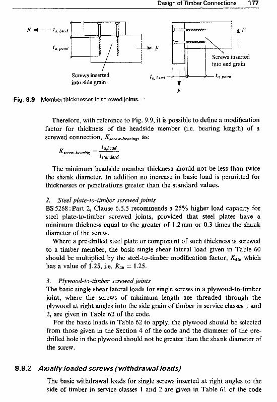
Design of Timber Connections 177
F "---- to, head
ta, yornt
into side grain F
Figg. 9.9 Member thicknesses in screwed joints.
Therefore, with reference to Fig. 9.9, it is possible to define a modification factor for thickness of the headside member (i.e. bearing length) of a screwed connection, Kscrew-bearing, as:
tu,head -&crewbearing -
tstundard
The m i ~ m u m headside member thickness should not be less than twice the shank diameter. In addition no increase in basic load is permitted for thicknesses or penetrations greater than the standard values.
2. Steel plate-to-timber screwed joints BS 5268 : Part 2, Clause 6.5.5 recommends a 25% higher load capacity for steel plate-to-timber screwed joints, provided that steel plates have a minimum thickness equal to the greater of 1.2 mm or 0.3 times the shank diameter of the screw,
Where a pre-drilled steel plate or component of such thickness is screwed to a timber member, the basic single shear lateral load given in Table 60 should be multiplied by the steel-to-timber modification factor, which has a value of 1.25, i.e. &6 = 1.25.
3. ~l~wood-to-timber screwed joints The basic single shear lateral loads for single screws in a pl~ood-to-timber joint, where the screws of minimum length are threaded through the plywood at right angles into the side grain of timber in service classes l and 2, are given in Table 62 of the code.
For the basic loads in Table 62 to apply, the plywood should be selected from those given in the Section 4 of the code and the diameter of the pre- drilled hole in the plywood should not be greater than the shank diameter of the screw.
The basic withdrawal loads for single screws inserted at right angles to the side of timber in service classes 1 and 2 are given in Table 61 of the code

178 Structural Timber Design
Table 9.9 Basic withdrawal loads per millimetre of pointside penetration for screws turned at right angles to grain (Table 61, BS 5268 : Part 2)
Screw Basic withdrawal loada, (N/mm)
Strength class
6 3.45 10.96 12.03 14.29 16.06 27.3 1 37.17 8 4.17 12.63 13.87 16.47 18.51 3 l .49 42.85
10 4.88 14.21 15.61 18.53 20.83 35.43 48.22 12 5.59 15.73 17.28 20.52 23.06 39.23 53.39 14 6.30 17.21 18.90 22.44 25.22 42.9 1 58.40 16 7.01 18.64 20.48 24.31 27.33 46.49 63.26 18 7.72 20.04 22.01 26.14 29.38 49.97 68.01
a The penetration of the screw point should not be less than 15 mm
(reproduced here as Table 9.9). The values apply to each 1 mm depth of actual pointside penetration achieved by the threaded part of the screw; where the penetration of the screw point should not be less than 15 mm.
No withdrawal load is permitted by the code for screws inserted into the end grain of timber.
9.8.3 Permissible load for a screwed joint
Clause 6.5.7 of I3S 5268 : Part 2 recommends that the permissible load for a screwed joint should be determined as the sum of the permissible loads for each screw in the joint, where each permissible screw load, Fah, should be calculated from the equation:
where: F is the basic load for a screw under shear (Tables 60 or 62) or
withdrawal loading (Table 61) and is taken from Clauses 6.5.4, 6.5.5.2 and 6.5.6.2 of the code, which were described earlier. Therefore F is given by:
for a screw under shear lateral load,
for a screw under axial (withdrawal) load with a pointside threaded penetration depth of tpoint,

Design of Timber Connections 179
K52
K53
K54
where: tathead
Kscrew-bearing ="----- tstandard
K43 = 0.7, for screwing into the end grain = 1.25, steel plate-to-timber modification factor.
is the modification factor for duration of loading
where: K52 = 1.00, for long-term loads = 1 12, for medium-term loads = 1.25, for short and very short-term loads.
is the modification factor for moisture content
where: K53 = 1.00, for a joint in service classes 1 and 2 = 0.70, for a joint in service class 3.
is the modification factor for the number of screws of the same diameter in each line, acting in shear, for an axially loaded member, loaded parallel to the line of screws
where: K54 = 1.00, for the number of screws in each line 10 = 0.9, for the number of screws in each line 2 10 = 1.00, for all other loading cases.
9.9 Bolted and dowelled joints
Dowels are cylindrical rods generally made of steel with a smooth surface, and are available in diameters ranging from 6-30mm. Bolts are threaded dowels with hexagonal or semi-sphere heads and hexagonal nuts. Dowels and bolts are commonly used in connections requiring higher shear capacity than the nailed or screwed joints, see Fig. 9.10. Threaded dowels with nuts and bolts are also used in axially loaded tension connections.
Both dowels and bolts are commonly used to hold two or more members together, but the most common connection type involves three or more members in a multiple shear arrangement. The side members can be either timber or steel. When bolts are used, washers are required under the bolt head and under the nut to distribute the loads. The recommended washer diameter is 3 times the bolt diameter (34 with a thickness of 0.25 times the bolt diameter (0.25d). When tightened, a minimum of one complete thread should protrude from the nut.
Dowelled joints are easy to fabricate. They are inserted into pre-drilled holes with a diameter not greater than the dowel diameter itself. They can produce stiffer joints compared to bolted ones which require 1 mm oversize

1 80 Structural Timber Design
(a) Dowel
(b) Bolts
Fig. 9.10 Typical dowel and bolts.
for clearance; BS 5268 : Part 2 recommends a maximum of 2 mm oversizing for bolt holes. If steel plates are incorporated in a dowelled connection, a 1 mm clearance must be provided and due allowance should then be made for the additional deformation that may occur.
ask s i ~ ~ l e shear lateral loads
l. Timber-to-timber bolted or dowelled joints The basic single shear lateral loads for a single bolt or dowel, with a mini- mum tensile strength of 400N/mm2, in a two-member timber joint, in which the load acts perpendicular to the axis of the bolt or dowel, and parallel or perpendicular to the grain of the timber, are given in Tables 63-68 of BS 5268 : Part 2. Table 64 is reproduced here as Table 9.10.
The basic loads appropriate to each shear plane in a t~ree-member joint under the same conditions are given in Tables 69-74 of the code. Table 70 is reproduced here as Table 9.1 1. Separate loads are tabulated for long-, medium- and short-duration loads and therefore there is no need to further modify the basic load values for duration of loading.
Unlike nails and screws, bolts and dowels have loading capacities that vary depending on the direction of the applied load with respect to the grain direction of the timber. This is why the code provides separate basic shear values for loadings parallel and perpendicular to the grain of timber, and recommends the use of Hankinson’s equation for determination of basic loads, F, in situations where the applied load is inclined at an angle a to the grain of the timber, see Fig. 9. l l , hence:
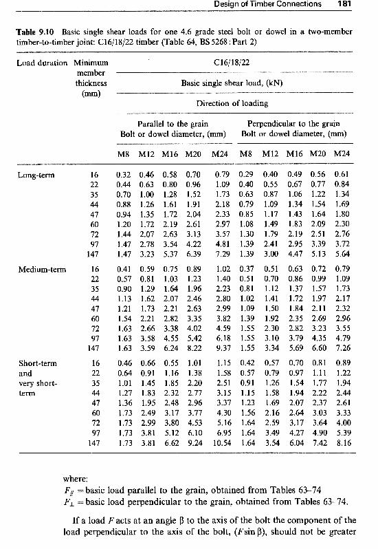
Design of Timber Connections 1
Table 9.10 Basic single shear loads for one 4.6 grade steel bolt or dowel in a two-member timber-to-timber joint: C16/18/22 timber (Table 64, BS 5268 : Part 2)
Load duration Minimum C 161 18/22 member thickness Basic single shear load, (kN) (m)
Direction of loading
Parallel to the grain Perpendicular to the grain Bolt or dowel diameter, (mm) Bolt or dowel diameter, (mm)
M8 M12 M16 M20 M24 M8 M12 M16 M20 M24
Long-term
Medium-term
Short-term and very short- term
16 22 35 44 47 60 72 97
147
16 22 35 44 47 60 72 97
147
16 22 35 44 47 60 72 97
147
0.32 0.46 0.58 0.70 0.44 0.63 0.80 0.96 0.70 1.00 1.28 1.52 0.88 1.26 1.61 1.91 0.94 1.35 1.72 2.04 1.20 1.72 2.19 2.61 1.44 2.07 2.63 3.13 1.47 2.78 3.54 4.22 1.47 3.23 5.37 6.39
0.41 0.59 0.75 0.89 0.57 0.81 1.03 1.23 0.90 1.29 1.64 1.96 1.13 1.62 2.07 2.46 1.21 1.73 2.21 2.63 1.54 2.21 2.82 3.35 1.63 2.66 3.38 4.02 1.63 3.58 4.55 5.42 1.63 3.59 6.24 8.22
0.46 0.66 0.55 1.01 0.64 0.91 1.16 1.38 1.01 1.45 1.85 2.20 1.27 1.83 2.32 2.77 1.36 1.95 2.48 2.96 1.73 2.49 3.17 3.77 1.73 2.99 3.80 4.53 1.73 3.81 5.12 6.10 1.73 3.81 6.62 9.24
0.79 0.29 0.40 0.49 0.56 0.61 1.09 0.40 0.55 0.67 0.77 0.84 1.73 0.63 0.87 1.06 1.22 1.34 2.18 0.79 1.09 1.34 1.54 1.69 2.33 0.85 1.17 1.43 1.64 1.80 2.97 1.08 1.49 1.83 2.09 2.30 3.57 1.30 1.79 2.19 2.51 2.76 4.81 1.39 2.41 2.95 3.39 3.72 7.29 1.39 3.00 4.47 5.13 5.64
1.02 0.37 0.51 0.63 0.72 0.79 1.40 0.51 0.70 0.86 0.99 1.09 2.23 0.81 1.12 1.37 1.57 1.73 2.80 1.02 1.41 1.72 1.97 2.17 2.99 l .09 1.50 1.84 2.1 1 2.32 3.82 1.39 1.92 2.35 2.69 2.96 4.59 1.55 2.30 2.82 3.23 3.55 6.18 1.55 3.10 3.79 4.35 4.79 9.37 1.55 3.34 5.69 6.60 7.26
1.15 0.42 0.57 0.70 0.81 0.89 1.58 0.57 0.79 0.97 1 . l 1 1.22 2.51 0.91 1.26 1.54 1.77 1.94 3.15 1.15 1.58 1.94 2.22 2.44 3.37 1.23 1.69 2.07 2.37 2.61 4.30 1.56 2.16 2.64 3.03 3.33 5.16 1.64 2.59 3.17 3.64 4.00 6.95 1.64 3.49 4.27 4.90 5.39
10.54 1.64 3.54 6.04 7.42 8.16
where: F1 =basic load parallel to the grain, obtained from Tables 63-74 FL =basic load perpendicular to the grain, obtained from Tables 63-74.
If a load F acts at an angle p to the axis of the bolt the component of the load perpendicular to the axis of the bolt, (Fsin p), should not be greater
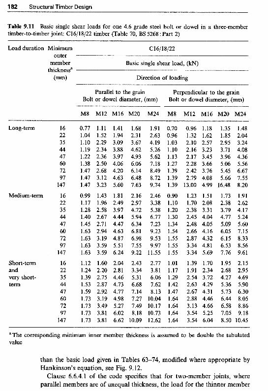
182 Structural Timber Design
Table 9.11 Basic single shear loads for one 4.6 grade steel bolt or dowel in a three-member timber-to-timber joint: C16/18/22 timber (Table 70, BS 5268 : Part 2)
Load duration Minimum C16/18/22 outer
thicknessa member Basic single shear load, (kN)
(mm) Direction of loading
Parallel to the grain Perpendicular to the grain Bolt or dowel diameter, (mm) Bolt or dowel diameter, (mm)
M8 M12 M16 M20 M24 M8 M12 M16 M20 M24
Long-term
Medium-term
Short-term and very short- term
16 22 35 44 47 60 72 97
147
16 22 35 44 47 60 72 97
147
16 22 35 44 47 60 72 97
147
0.77 1.11 1.41 1.04 1.52 1.94 1.10 2.29 3.09 1.19 2.34 3.88 1.22 2.36 3.97 1.38 2.50 4.06 1.47 2.68 4.20 1.47 3.12 4.63 1.47 3.23 5.60
0.99 1.43 1.81 1.17 1.96 2.49 1.28 2.58 3.97 1.40 2.67 4.44 1.45 2.71 4.47 1.63 2.94 4.63 1.63 3.19 4.87 1.63 3.59 5.51 1.63 3.59 6.24
1.12 1.60 2.04 1.24 2.20 2.81 1.39 2.75 4.46 1.53 2.87 4.73 1.59 2.92 4.77 1.73 3.19 4.98 1.73 3.49 5.27 1.73 3.81 6.02 1.73 3.81 6.62
1.68 2.3 1 3.67 4.62 4.93 6.06 6.14 6.48 7.63
2.16 2.97 4.72 5.94 6.34 6.81 6.98 7.55 9.22
2.43 3.34 5.31 6.68 7.14 7.27 7.49 8.18
10.09
1.91 0.70 0.96 1.18 1.35 1.48 2.63 0.96 1.32 1.62 1.85 2.04 4.19 1.03 2.10 2.57 2.95 3.24 5.26 1.10 2.16 3.23 3.71 4.08 5.62 1.13 2.17 3.45 3.96 4.36 7.18 1.27 2.28 3.66 5.06 5.56 8.49 1.39 2.42 3.76 5.45 6.67 8.72 1.39 2.79 4.08 5.66 7.55 9.74 1.39 13.00 4.99 16.48 8.20
2.46 0.90 1.23 1.51 1.73 1.91 3.38 1-10 1.70 2.08 2.38 2.62 5.38 1.20 2.38 3.31 3.79 4.17 6.77 1.30 2.45 4.04 4.77 5.24 7.23 1.34 2.48 4.05 5.09 5.60 9.23 1.54 2.66 4.16 6.05 7.15 9.53 1.55 2.87 4.32 6.15 8.33 9.97 1.55 3.34 4.81 6.53 8.56
11.55 1.55 3.34 5.69 7.76 9.61
2.77 1.01 1.39 1.70 1.95 2.15 3.81 1.17 1.91 2.34 2.68 2.95 6.06 1.29 2.54 3.72 4.27 4.69 7.62 1.42 2.63 4.29 5.36 5.90 8.13 1.47 2.67 4.31 5.73 6.30
10.04 1.64 2.88 4.46 6.44 8.05 10.17 1.64 3.13 4.66 6.58 8.86 10.73 1.64 3.54 5.25 7.05 9.18 12.62 1.64 3.54 6.04 8.50 10.45
aThe corresponding minimum inner member thickness is assumed to be double the tabulated value
than the basic load given in Tables 6374, modified where appropriate by Hankinson’s equation, see Fig. 9.12.
Clause 6.6.4.1 of the code specifies that for two-member joints, where parallel members are of unequal thickness, the load for the thinner member

Design of Timber Connections 183
I Load
1' I-
"J"_
Applied load is acting J "- j "_ 1 . perpendicular to the
i grain of the horizontal member
Load
Applied load is acting at an angle a to the grain of the horizontal member
Fig. 9.11 Load at an angle to the grain.
F cos p
F Fsin p
Fig. 9.1 2 Load at an angle to the axis of the bolt.
should be used. Where members of unequal thickness are joined at an angle, the basic load for each member should be determined, using Hankinson's equation, and the smaller load should be used.
For three-member joints, the basic loads given in Tables 69-74 apply to joints where the outer members have the tabulated thickness and the inner member is twice as thick. For other thicknesses the load should be taken as

1 Structural Timber Design
the lesser of the loads obtained by linear interpolation between the two adjacent tabulated thicknesses for each member.
The basic load for a joint with more than three members should be taken as the sum of the basic loads for each shear plane, assuming that the joint consists of a series of three-member joints.
2. Steel plate-to-timber bolted or dowelled joints BS 5268 : Part 2, Clause 6.6.5.1 recommends a 25% higher load capacity for steel plate-to-timber bolted or dowelled joints, provided that steel plates have a minimum thickness equal to the greater of 2.5mm or 0.3 times the bolt or dowel diameter.
Where a steel plate or component of such thickness is bolted or dowelled to a timber member, the basic loads given in Tables 63-74 should be multiplied by the steel-to-timber modification factor, &G, which has a value of l .25, i.e. K46 = 1.25.
In dowelled joints where the steel plates are used as the side (outer) mem- bers of the joint, the steel plates should be secured in position adequately, i.e. by threading and applying nuts to the dowel ends or by welding dowel ends to the steel plates.
No increase should be made to the basic load when the timber is loaded perpendicular to the grain.
le load for a ~o l ted or do welled j o j ~ t
Clauses 6.6.6 and 6.6.7.4 of BS 5268 :Part 2 state that the permissible load for bolted or dowelled joints should be determined as the sum of the permissible loads for each bolt or dowel in the joint, where each permissible bolt or dowel load, Fuh , should be calculated from the equation:
where: F is the basic load for a bolt or dowel under lateral loading per shear
plane (Tables 63-74) and is taken from Clauses 6.6.4, 6.5.5 and 6.6.7 of the code which were described earlier. Therefore F is given by:
(a) for a bolt or dowel in a two-member joint,
F = F b a i c (Tables 63-68) X K46 (9.11)
(b) for a bolt or dowel in a symmetrical three-member joint
F = F b a i c (Tables 69-74) X 2 X K46 (9.12a)
(c) in general, for a bolt or dowel in a joint with three or more members,
F = x Fbaic (Tables 69-74) X &6 (9.12b)

Design of Timber Connections 185
K56
K57
where: Fbmfc = sum of the modified basic loads
K46 = l .25, steel plate-to-timber modification factor.
It is to be noted that in all cases, if load is applied at an angle a to the grain of timber, Fbmic is obtained from
FIIFJ- Fbmic I== F1 sin2 a + FL cos2 a
is the modification factor for moisture content
where: K56 = 1.00, for a joint in service classes 1 and 2
=0.70, for a joint made in timber of service class 3 and used in
= 0.40, for a joint made in timber of service class 3 but used in that service class
service classes l and 2.
is the modification factor for the number of bolts or dowels of the same diameter in each line acting in shear for an axially loaded member, loaded parallel to the line of bolts or dowels, where:
3(n - 1) K57 = 1 -- 100 for n < 10
= 0.7 for n 2 10 = 1.0 for all other loading cases
where n is the number of bolts or dowels in each line.
Structural connections are often required to transmit moments as well as shear andlor axial forces. Figure 9.13 presents some examples of moment- resisting timber joints such as (a) a splice joint in a continuous beam, (b) a moment-resisting column base and (c) a knee joint in a frame. Although in this section a bolted connection is used to illustrate a simplified analysis method for determination of connection moment capacity, the method can similarly be applied to nailed, screwed, or, indeed, dowelled joints.
Figure 9.14(a) shows a bolted connection which is subjected to a moment of M, and shear and normal forces of Vand H. The effects of the moment M and the forces V and H, all acting at the geometric centre of the bolt group at C, can be considered separately.
First consider the effect of the applied moment, M. For an elastic behaviour of the connection, we can assume that the moment, M, will induce a shearing force, FM, in any of the bolts perpendicular to the line

""-""
i
M M
Fig. 9.1 3 Moment-resisting connections.
(a) Connection subjected to M, Vand H
(c) Effect of the applied shear force V
- -. """""
(b) Effect of the applied moment M
,' '\\
(d) Effect of the applied normal force H
Fig. 9.14 Moment-resisting joint subjected to an applied moment and shear and normal forces.

Design of Timber Connections 187
joining C to the bolt. Therefore the force FM will be perpendicular to the distance r from the bolt to C (see Fig. 9.14(b)). For equilibrium we have:
M = FMer (9.13)
If we consider FM = k . r, where k is constant for all bolts, then
M = k x r 2
Thus, M k = - c r2
(9.14)
By substituting for k, the force acting on a bolt due to the moment, M, becomes:
M FM=- r2 ' (9.15)
where: c r 2 = r ~ + r ~ + r ~ + r ~ + r ~ + - - * . As an example, the force acting on the bolt a due to the applied moment M is:
Now considering the effects of shear* and normal forces V and H, assume that each one is distributed equally among the bolts as a shearing force parallel to the line of action of V and/or H (see Fig. 9.14(c), (d)). For a joint with n number of bolts,
the force exerted on a bolt due to the applied shear force V is, V n
F y = - (9.16)
the force exerted on a bolt due to the applied normal force H is, H F H = - n
(9.17)
The total force acting on a bolt can then be calculated as the vectorial summation of FM, Fv and FH. For example, the total force acting on the bolt a, Fa, with its angle of inclination to the grain of timber, a, is obtained as illustrated in Fig. 9.15.
a / ,
I I
I I
Fig. 9.1 5 Vectorial summation of fa,^, FV and FH acting on the bolt a.

1 Structural Timber Design
With forces defined by equations 9.15-9.17, moment resisting joints, with rectangular pattern, can be designed so that the load on the furthest fastener (i.e. fastener a) is not greater than the permissible load value. The total force, Fa, acting on the furthest fastener a can be calculated from:'
acting at an angle a to the grain of timber where:
(9.19)
A moment-resisting connection with a circular pattern, such as that of joint (c) shown in Fig. 9.13, can be designed considering the load on the fast- ener located on the longitudinal axis. In such cases the total force on the fastener is given by:
acting at an angle a where:
a = arctan ( F~ ) FM + FV
(9.20)
(9.21)
It is to be noted that for connections with parallel members, Hankinson's formula (equation 9.9) should be used for the calculation of the permissible loads for bolts or dowels loaded at an angle a to the grain of timber. For timber-to-timber connections with members perpendicular to each other, a modified version of Hankinson's formula may be used. Therefore:
for a timber-to-timber bolted or dowelled connection with parallel members or steel-to-timber, the basic single shear load is given by:
for bolted or dowelled connections with perpendicular members,'
(9.22)
Timber connectors are the most efficient of all mechanical fasteners, as they improve the transfer of loads by increasing the bearing area between the fasteners and the timber. They are generally in the form of rings, discs or plates, partially embedded in the faces of adjacent timber members, to transmit the load from one to the other. There are several types of timber
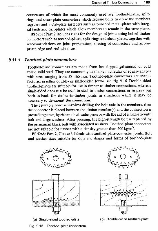
Design of Timber Connections
connectors of which the most commonly used are toothed-plates, split- rings and shear-plate connectors which require bolts to draw the members together and metal-plate fasteners such as punched metal-plates with integ- ral teeth and nail-plates which allow members to remain in the same plane.
BS 5268 :: Part 2 includes rules for the design of joints using bolted timber connectors such as toothed-plates, split-rings and shear-plates, together with recommendations on joint preparation, spacing of connectors and appro- priate edge and end distances.
Toothed-plate connectors are made from hot dipped galvanise rolled mild steel. They are commonly available in circular or square shapes with sizes ranging from 38-165mm. Toothed-plate connectors are manu- factured in either double- or single-sided forms, see Fig. 9.16. ~ouble-sided toothed-plates are suitable for use in timber-to-timber connections, whereas single-sided ones can be used in steel-to-timber connections or in pairs put back-to-back for timber-to-timber joints in situations where it may be necessary to de-mount the c~nnection.~
The assembly process involves drilling the bolt hole in the members, then the connector is placed between the timber member(s) and the connection is pressed together, by either a hydraulic press or with the aid of a ~gh-strength bolt and large washers. After pressing, the high-strength bolt is replaced by the permanent black bolt with associated washers. Toothed-plate connectors are not suitable for timber with a density greater than 500 kg/m3. BS 5268 : Part 2, Clause 6.7 deals with toothed-plate connector joints. Bolt
and washer sizes suitable for different shapes and forms of toothed-plate
(a) Single-sided toothed-plate (b) Double-sided toothed-plate
Fig. 9.1 6 Toothed-plate connectors.
I90 Structural Timber Design
connectors are detailed in Table 76 of the code, and recommendations for the spacing, end and edge distances are given in Tables 77-79.
The basic loads parallel and perpendicular to the grain of the timber for toothed-plate connector units are given in Table 80 of the code. The basic loads apply to softwoods and hardwood, in strength classes C14 to C40, TR26 and D30 to D40, provided that the teeth of the connectors can be fully embedded.
Permissible load for a toothed-plate connectored joint
Clause 6.7.6 of BS 5268 : Part 2 recommends that the permissible load for a toothed-plate connectored joint be determined as the sum of the permissible loads for each unit in the joint, where each permissible load, Fah, should be calculated from the equation:
Fadm = x KSSK59&0&il (9.23)
where: I; is the basic load for a toothed-plate under single shear loading
(Table 80) It is to be noted that if load is applied at an angle M, to the grain of timber, F is obtained from
is the modification factor for duration of loading
where: K58 = 1 .OO, for long-term loads = 1.12, for medium-term loads = 1.25, for short and very short-term loads.
K59 is the modification factor for moisture content
where: = 1.00, for a joint in service classes 1 and 2 =0.70, for a joint in service class 3.
K60 is the modification factor for end distance
where: 1y60 = 1.00 if the standard edge and end distances and spacing given in
Tables 77-79 are used, otherwise the lesser of Kc and Ks as given in Tables 81, 82 and 79 of the code should be used.
is the modification factor for the number of connector units of the same size in each line for an axially loaded member, loaded parallel to the line of connectors
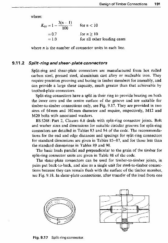
Design of Timber Connections 191
where: 3(n - l ) K(j1 = l --
100 for n < 10
= 0.7 for n 2 10 = 1.0 for all other loading cases
where n is the number of connector units in each line.
9.1 1.2 lit-ring and shear-plate connectors
Split-ring and shear-plate connectors are manufactured from hot rolled carbon steel, pressed steel, aluminium cast alloy or malleable iron. They require precision grooving and boring in timber members for assembly, and can provide a large shear capacity, much greater than that achievable by toothed-plate connectors.
Split-ring connectors have a split in their ring to provide bearing on both the inner core and the centre surface of the groove and are suitable for timber-to-timber connections only, see Fig. 9.17. They are provided in two sizes of 64 mm and 102 mm diameter and require, respectively, M 12 and M20 bolts with associated washers. BS 5268 :Part 2, Clauses 6.8 deals with split-ring connector joints. Bolt
and washer sizes and dimensions for suitable circular grooves for split-ring connectors are detailed in Tables 83 and 84 of the code. The recommenda- tions for the end and edge distances and spacings for split-ring connectors for standard dimensions are given in Tables 85-87, and for those less than the standard dimensions in Tables 89 and 90.
The basic loads parallel and perpendicular to the grain of the timber for split-ring connector units are given in Table 88 of the code.
The shear-plate connectors can be used for timber-to-timber joints, in pairs put back-to-back, and also as a single unit for steel-to-timber connec- tions because they can remain flush with the surface of the timber member, see Fig. 9.18. In shear-plate connections, after transfer of the load from one
Fig. 9.1 7 Split-ring connector.
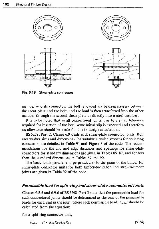
192 Structural Timber Design
Shear-plate connectors.
member into its connector, the bolt is loaded via bearing stresses between the shear-plate and the bolt, and the load is then transferred into the other member through the second shear-plate or directly into a steel member.
It is to be noted that in all connectored joints, due to a small tolerance required for insertion of the bolt, some initial slip is expected and therefore an allowance should be made for this in design calculations.
S 5268 :Part 2, Clause 6.9 deals with shear-plate connector joints. and washer sizes and dimensions for suitable circular grooves for split-ring connectors are detailed in Table 91 and Figure 8 of the code. The recom- mendations for the end and edge distances and spacings for shear-plate connectors for standard dimensions are given in Tables 85-87, and for less than the standard dimensions in Tables 89 and 90.
The basic loads parallel and perpendicular to the grain of the timber for shear-plate connector units for both timber-to-timber and steel-to-timber joints are given in Table 92 of the code.
Clauses 6.8.5 and 6.9.6 of BS 5268 : Part 2 state that the permissible load for such connectored joints should be determined as the sum of the permissible loads for each unit in the joint, where each permissible load, F a h , should be calculated from the equation:
for a split-ring connector unit,

Design of Timber Connections 1
for a shear-plate connector unit,
Fah = F x K66K67K68K69
5 (the limiting values given in Table 93) (9.25)
is the basic load for a split-ring or shear-plate connector unit under single shear loading (Tables 88 and 92 respectively).
It is to be noted that if load is applied at an angle a to the grain of timber, F is obtained from:
F = F P J - F), sin2 a + FJ- cos2 a
are the modification factors for duration of loading
where: K62166 = 1 .oo, for long-term loads
= 1.25, for medium-term loads = 1.50, for short and very short-term loads.
are the modification factors for moisture content where:
= 1.00, for a joint in service classes 1 and 2 = 0.70, for a joint made in timber of service class 3,
are the modification factors for end distance
where: = 1.00, provided that the standard edge distance, end
distance and spacings given in Tables 85-87 are used, otherwise K64 and are equal to the lesser of Ks , K c and KD as given in Tables 87, 89 and 90 of the code.
, are the modification facto& for the number of connector units of the same size in,,each line for an axially loaded member, loaded parallel to the line of connectors
where:
3(n - 1) &55/69 = 1 - 100 for n < 10
= 0.7 for n 2 10 = 1.0 for all other loading cases
where n is the number of connector units in each line.
tal- fate connectors
These are light-gauge metal-plates with integral projections (teeth) punched out in one direction and bent perpendicular to the base of the plate, and are

1 94 Structural Timber Design
(a) Punched metal-plate
Fig. 9.19 Metal-plate connectors.
(b) Nail-plate
referred to as punched ~ e t a l - ~ z a t e s . Metal-plates with pre-formed holes that depend on nails for load transfer may also fall into this category (and are referred to as nail-~l~tes) , see Fig. 9.19. Both types are generally used to join two or more sections of timber of the same thickness in one plane.
Punched metal-plates and nail-plates are generally manufactured from pre-galvanised mild steel strips or stainless steel strips. Their thickness ranges from 0.9 mm to 2.5 mm for punched metal-plates and around l .O mm for nail-plates. Manufacturers of nail-plates recommend the use of improved nails, such as square twisted nails, which should be a tight driven fit in the plate holes.
Punched metal-plate fasteners are suited to factory prefabrication and are able to transfer member forces via small connection areas. They are widely used to form truss connections as well as joints in many other plane-frame timber structures. Loads are transferred in a punched metal-plate from the timber member into the plate teeth, then from the teeth into the steel plate and across the joint interface, then back down into the teeth in the other member. Joints are designed and constructed with pairs of plates on their opposite sides.173
Many different forms of punched metal-plate fastener have been devel- oped, involving a variety of nail patterns, nail sizes and lengths and nail shapes. Most of these are manufactured and used by individual manufac- turers in their prefabricated timber products, for example, roof trusses. As such, their strength and slip characteristics are not available in the litera- ture, but they still have to satisfy the recommendations of the related British Standards, in particular BS 5268 : Part 3 : 1998 Code of practice for trussed rafter roofs.

Design of Timber Connections 195
9.12 Glued joints
Another form of structural jointing system in timber is gluing, with a history going back many centuries. If gluing is used correctly it can offer the advantages of strong, rigid and durable joints with a neat appearance. Since the beginning of this century modern synthetic adhesives have been used successfully in many structural applications, including glued laminated constructions and finger-jointing systems.
Nowadays there are several types and forms of adhesives available that can be applied to timber and wood based products; but those for use in the assembly of structural components should comply with the require- ments of BS EN 301 : 1992 Adhesives, phenolic and aminoplastic~ for load- bearing timber structures: classijication and performance requirements, and/ or BS 1204: 1993 Specijication for type MR phenolic and aminoplastic synthetic resin adhesives for wood.
In glued joints, the glue should always be stronger than the surrounding timber (i.e. if it is tested to destruction, failure should occur in timber and not in the thickness of the glueline). A glued joint has a much lower strength in tension than in shear and for this reason joints should be designed so that any tension effect on the glueline is prevented. BS 5268 : Part 2, Clause 6.10 recommends that eccentric glued lap joints which induce a tensile com- ponent of stress perpendicular to the plane of the glueline should not be permitted. Therefore overlapped glued joints should always have symme- trical member and loading arrangements to induce pure shear at gluelines, see Fig. 9.20.
9.1 2.1 Durability classification
The performance of glues, particularly in relation to durability, is an impor- tant criterion for an appropriate selection of a glue type and specification by the designer. BS 5268 : Part 2, Clause 6.10.1.2 recommends that the adhesive used should be appropriate to environmental conditions in which the joint will be used. Table 94 of the code provides details of four exposure cat- egories, the permitted adhesive types and the British Standard classifications and references.
Fig. 9.20 An overlapped glued joint.
As mentioned earlier, if a glued timber joint complies with the required recommendations, the glueline(s) will be subjected to pure shear and will be stronger than the surrounding timber. Therefore the design capacity of a glued connection can be calculated as the permissible shear stress on the interfaces of the timber or wood panel products being glued. Service class, load-duration and load-sharing modification factors (K2, K3 and Kg) apply because stresses in the connection are those of timber stresses.
The glued joint must be held in close contact during curing, and the pressure is best applied by clamps which are removed after curing, or by nails or staples which are left in the final assembly. In the event where bonding pressure is generated by nails or staples, the code recommends that the permissible shear stress be multiplied by the naillglue modification factor, K70, which has the value 0.9, i.e. K70 = 0.9.
In the event of a glued joint being designed so that one face is loaded at an angle a to the direction of the grain, the permissible shear stress for the glueline should be calculated using the following equation:
T~ = T a b , / ( 1 - 0.6’7 sin a) (9.26)
where a
= a b , /
is the angle between the direction of the load and the grain of the piece is the permissible shear stress parallel to the grain for the timber and may be determined from:
The permissible shear stress for a joint made with different timbers and or wood based panel products (i.e. plywood or particleboard) should be taken as the permissible shear stress for the timber or the approp~ate rolling shear stress for the wood based product, whichever has the lower value.
erences
Timber Engineering - STEP I , Section C ( l 995) Centrum Hout, The Netherlands. TRADA (1995) Dowel-type fasteners for structural timber. Wood I n f o r ~ a t i o ~ ? Section 2/3, Sheet 52. Timber Research and Development Association (TRADA), High Wycombe. TRADA (1996) Connectors and metal plate fasteners for structural timber. Wood Information, Section 2/3, Sheet 53. TRADA, High Wycombe.

Design of Timber Connections 197
S
The nailed joint shown in Fig. 9.21 is subjected to medium-term tensile loading under e joint comprises six 3.00 mm diameter x 60 mm long round wire nails
acting in single shear in C18 timber. Determine the load-carrying capacity of the connection.
a4f3-4 a2 4 4 I l l l l l
-4 4 4 l l I I l I 1 I
I
I I I +"-+ a3 aI
97 m
1 Nailed joint details (Example 9.1 ).
Force, kN Length, m Cross-sectional dimensions, mm Stress, Nmm"2
Nail diameter, d Nail length, Znaif
NO. of nails, nnail Head side penetration, ta,head Pointside penetration, ta,point
BS5268 : Part 2, Table 54 Strength class, C18 timber Standard penetration, tstandard Basic single shear lateral
load, Fbasic
N := newton kN := lo3 + N Direction parallel to grain, // Direction perpendicular to grain, pp

198 Structural Timber Design
3. ~ o ~ i f i c a t i o n factors
BS S268 : Part 2 , Clause 6.4 Number of shear planes, nshear No pre-drilling
Nail bearing is the lesser of
and
Mathcad command to select the minimum value
Thus Side grain nailing, K43 does
Ordinary nails, KM does
Timber-to-timber nailing, K46
not apply
not apply
does not apply
ta.point Knail.bearing.2 := ~
tstandard
Knail.bearing.2 = 0.75 KnaiLbearing := [KnaiLbearing. 1 Knail.bearing.21 Pnill(Kmil.bearhg) = 0.75 > 0.66 (Clause 6.4.4.1)
okay KnaiLbearing := min(Knail.bearing) K 4 3 := 1
KM := 1
Load duration, medium-term K48 := l . l2 Moisture content, K&, service K49 := 1
No. of nails, <lo, in one line, K5, K50 := 1 class 2
4. Permissible load
5. Minimum nail spacings
BS5268 : Part 2 , Table 53 For softwoods other than Douglas fir, nail spacing should be multiplied by 0.8 but the edge distance 2 5d.
End distance // to grain, a3 a3 := 0.8 w20. d
Edge distance perpendicular a 4 := 5 . d a 3 = 48 o mm
to grain, a4 a 4 = 150mm

Design of Timber Connections 199
Distance between lines of nails a2 := 0.8 - 10 d perpendicular to grain, a2 a2 = 24 o mm
Distance between adjacent nails a1 := 0.8 v20 d in any one line // to grain, a1 a1 = 48 o mm
6. Joint slip
BS5268 : Part 2, Clause 6.2 and Table 52 Cl 8 timber Characteristic density (Table 7) p := 320 kg m-3
Slip modulus: Since the equation for slip modulus is an empirical one (i.e. with hidden units in the coefficient part), for Mathcad to produce correct units, multiply it by the units shown inside the parentheses; or alternatively, use the equation without units for p and d.
Thus, slip modulus, K,,, 1 1.5 d0.8 (kg-1.5 . m2.7 . N , 105.4) &er := B * P Kser = 551.42 o N mm"'
Slip per nail, U, under permissible load
U = 0.4'7 o mm
heref fore the load capacity of the joint is 1.55 kN with a joint slip of 0.47 mm
€ x a ~ ~ l e 9.2 ~ e s i ~ n of a t i~ber - to - t i~ber connection with nail~n the end ~ r a i ~
The nailed connection shown in Fig. 9.22 is subjected to short-term loading under service class 2 conditions. The joint comprises two 3.75 mm diameter x 65 mm long round wire nails acting in single shear in C22 timber. Determine the load capacity of this connection.
P
Nails driven into
P
Fig. 9.22 Nailed joint details (Example 9.2).

2 Structural Timber Design
Force, kN Length, m Cross-sectional dimensions, mm Stress, Nmm-2
1 m ~ e o ~ e t r i c a l details
Nail diameter, d Nail length, lnail NO. of nails, nnail
Head side penetration, ta,head
Pointside penetration, ta,poht
BS'5268 : Part 2, Table 54 Strength class, C22 timber Standard penetration, tsgandard
Basic single shear lateral load, Fbasic
a ~ j o ~ factors
BS5268 : Part 2, Clause 4 . 6 Number of shear planes, nshear No pre-drilling
Nail bearing is the lesser of
and
athcad command to select the minimum value
Thus End grain nailing, does
Ordinary nails, KM does
Timber-to-timber nailing, K46
not apply
not apply
does not apply
N :=newton
Direction parallel to grain, // Direction perpendicular to grain, pp
:= 103. N
Knail.bearing.2 := p
ta.point
tstandard
Knail.bearing.2 0.71 Knail.bearing := [Knail.bearing.l Knail.bearing.2] min(K,ail.bearing) = 0.71 > 0.66 okay KnaiLbearing := min(Knail.bearing) K43 := 0.7
K44 := 1

Design of Timber Connections 201
Load duration, &g7 short-term &8 := 1.25 Moisture content, &g, service &9 := 1
No. of nails, <lo, in one line, K50 K50 := 1 class 2
BS5268 : Part 2, Clause 6.2 and Table 52 C22 timber Characteristic density (Table 7) p := 340 kg - m-3
Slip modulus: Since the equation for slip modulus is an empirical one (i.e. with hidden units in the coefficient part), for Mathcad to produce correct units, multiply it by the units shown inside the parentheses; or alternatively, use the equation without units for p and d.
Thus, slip modulus, Kser Kser := * p 1.5 . d0.8 . (kg-l.5 . m2.7 . N 105.4) K'er = 721.94 o N * mm-'
Slip per nail, U , under permissible load
Fah -&er
U := -
U = 0.38 o mm
le
The nailed joint shown in Fig. 9.23 is subjected to long-term tensile loading under service class 1 conditions. The joint comprises six 3.35 mm diameter x 100 mm long helical-threaded shank nails acting in double shear in C18 timber. Determine the load capacity of this connection.
Force, kN N :=newton Length, m kN := lo3 N Cross-sectional dimensions, mm Direction parallel to grain, // Stress, NmmV2 Direction perpendicular to grain, pp
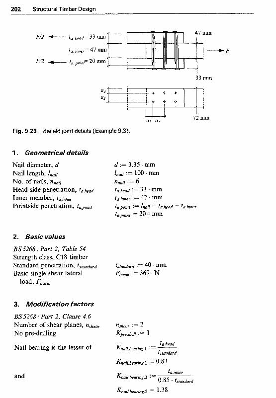
202 Structural Timber Design
P/2
P/2
33 m
a4 J a2 Y f ~, i o . + 4
l
a3 a1 72 mm
Fig. 9.23 Naileld joint details (Example 9.3).
1 . ~ e o ~ e t ~ i ~ a l details
Nail diameter, d Nail length, lnail
NO. of nails, nnail
Head side penetration, ta,head Inner member, ta,inmr Pointside penetration, t a p k t
135'5268 : Part 2, Table 54 Strength class, CS8 timber Standard penetration, tstandard Basic single shear lateral
load, Fbasic
d i f i c a t i ~ ~ factors
BS5268 : Part 2, Clause 4.6 Number of shear planes, nshear
No pre-drilling
Nail bearing is the lesser of
and

Design of Timber Connections 203
and ta.point Knail.bearmg.3 := ~
tstandard
Knail.bearing.3 = 0.5 Mathcad command to select KnaiLbearing := [Knail.bearing.1 Knail.bearing.2 Knail.bearing.31
the minimum value min(Knail.bearing) = 0.5 (Clause 6.4.4.1) okay Thus KnaiLbearing := min(Knail.bearing)
Side grain nailing, l&3 does &3 := 1
Improved nails, KM does KM := 1.2
Timber-to-timber nailing, &6 := 1
Load duration, &S, long-term &8 := 1 Moisture content, K&, service K 4 9 := 1
No. of nails, <lo, in one line, K50 K50 := 1
not apply
not apply
does not apply
class 2
4. Permissible load
5. Minimum nail spacings
BS5268 : Part 2, Table 53 For softwoods other than Douglas fir, nail spacing should be multiplied by 0.8 but the edge distance 2 5d.
End distance // to grain, a 3 a 3 := 0.8 20 d a 3 = 53.6omm
Edge distance perpendicular a 4 := 5 . d to grain, a4 a 4 = 16.75 o mm
Distance between lines of nails a 2 := 0.8 10 d perpendicular to grain, a 2 a 2 = 26.8 o mm
Distance between adjacent nails a1 := 0.8 a20 d in any one line // to grain, a1 a1 = 53.6 0 mm
6. Joint slip
BS5268 : Part 2, Clause 6.2 and Table 52 C18 timber Characteristic density (Table 7) p := 320 kg m-3

2 Structural Timber Design
Slip modulus: Since the equation for slip modulus is an empirical one (i.e. with hidden units in the coeflicient part), for Mathcad to produce correct units, multiply it by the units shown inside the parentheses; or alternatively, use the equation without units for p and d.
hus, slip modulus, Kser Kser := h. p"-5 . do-8 . (kg"-5 . m2.7 . N . 105.4)
K& = 602.31 0 N * mm"
Slip per nail, U, under permissible load
e load c a ~ a c i ~ of t
Design of an eave joint of a roof truss is required. The joint is to comprise a Finnish conifer plywood (9 mm thick, 7-ply) gusset with 3.00mm diameter x 50 mm long round wire nails acting in single shear. The rafter and ceiling tie are both in Cl8 timber under service class 2 conditions and are subjected to medium-term loading, as shown in Fig. 9.24(a).
4.18
Plywood gusset : 9 m 7-ply Finnish conifer
47 x 97 m C 18 timber 2.13 krN
Fig. 9 . 2 ~ ( ~ ) Nailed plywood gusseted joint (Example 9.4).
Force, kN N := newton Length, m kN := lo3. N Cross-sectional dimensions, mm Direction parallel to grain, // Stress, Nmrn"* Direction perpendicular to grain, pp
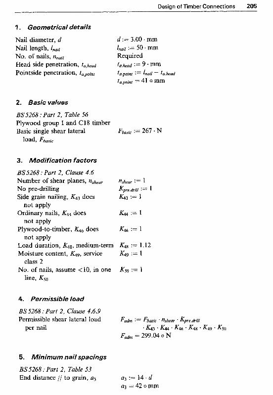
Design of Timber Connections 205
Nail diameter, d d := 3.00 + mm Nail length, lnail Znail := 50 * mm NO. of nails, nnail Required Head side penetration, ta,head ta.head := 9 * mm Pointside penetration, ta,point ta.point := lnail - ta.head
ta-point = 41 0 mm
BS5268 : Part 2, Table 56 Plywood group I and C18 timber Basic single shear lateral Fbmic := 267 * N
load, Fbasic
BS.5268 : Part 2, Clause 4.6 Number of shear planes, nshear No pre-drilling Side grain nailing, &3 does
not apply Ordinary nails, KM does
not apply Plywood-to-timber, K46 does
not apply Load duration, K48, medium-term Moisture content, service
No. of nails, assume < 10, in one class 2
line, K50
K4.4 := l
K50 := 1
BS5268 : Part 2, Clause 4.6.9 Permissible shear lateral load Fadm := Fbasic %hear Kpre.drill
per nail * K 4 3 * K44 K46 ' K48 K49 ' K50 Fadm = 299.04 0 N
BS5268 : Part 2, Table 53 End distance // to grain, a3 a3 := 14 d
a3 = 4 2 o m m
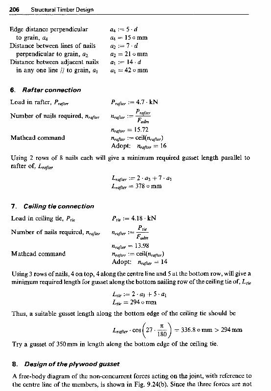
206 Structural Timber Design
Edge distance perpendicular to grain, a4
Distance between lines of nails perpendicular to grain, a2
Distance between adjacent nails in any one line // to grain, al
6. Rafter connection
Load in rafter, Prafter
Number of nails required, nraffer
Mathcad command
a4 := 5 * d a4 = 15 omm a2 := 7 . d a2 = 21 0 mm a1 := 14 d a1 = 42 0 mm
Using 2 rows of 8 nails each will give a rninimum required gusset length parallel to rafter of, Lraffer
7. Ce ihg tie connection
Load in ceiling tie, P t i e P t k := 4.18 * kN Ptie Number of nails required, nrafter nrafter := - Fah
nrafter = 13.98 Mathcad command nrafter := CeiKnrafter)
Adopt: nrafter I= 14
Using 3 rows of nails, 4 on top, 4 along the centre line and 5 at the bottom row, will give a minimum required length for gusset along the bottom nailing row of the ceiling tie of, Ltie
L,, := 2 . a3 $- 5 a1 Ltk = 294 o mm
Thus, a suitable gusset length along the bottom edge of the ceiling tie should be
Lrafter * COS (27 G) = 336.8 o mm > 294mm
Try a gusset of 350mm in length along the bottom edge of the ceiling tie.
8. Design of the plywood gusset
A free-body diagram of the non-concurrent forces acting on the joint, with reference to the centre line of the members, is shown in Fig. 9.24(b). Since the three forces are not

Design of Timber Connections 207
Fig. 9.24( b) Free-body diagram.
coincident the free-body is not in full equilibrium (i.e. the sum of the moments of the forces (say about point 0) is not equal to zero). Thus, the applied non-concurrent force system will induce a moment of M, at the joint, which should be resisted by the plywood gusset plate. In addition, the plywood gusset should also be able to resist a shearing force of F = 4.7 kN acting along an axis parallel to the rafter and passing through the interface between the ceiling tie and the rafter (i.e. along x-x).
Therefore, the balancing moment, M, is
Plywood thickness, t
Length of the gusset along the rafter, h
Section modulus, z
Stress due to bending moment
Shearing stress along x-x
Total stress acting along x-x
M := (2.13 kN) . (106. mm) M = 0.23 o kN m t :=9 .mm
h = 392.81 o mm t h2
z := - 6
z = 2.31 x lo5 o mm3 M
G m :=- z
G m = 0.98 o N mm-2 4.7 * kN
G, := ~ t * h CY, = 1.33 o N mm-2 Dtota l := G m t- Gs Gtotal = 2.3 0 N mm"2

208 Structural Timber Design
BS5268 : Part 2, Tuble 41 Grade panel shear zg := 3 . 7 4 - ~ * m m - ~ Modification factor for plywood K36 := 1.33
grade stresses for medium-term (K-36, Table 33)
Permissible panel shear in T&n := Tg * K36 plywood l;,& = 4.97 0 N * m m - 2
Plywood size is $ a ~ s f a c t o ~
Ceiling tie: 47 x 9 7 m
Rafter member:
Plywood gusset: 9 mm 7-ply Finnish conife
C18 ti
@ 42 m centres along tie // 350m->
Fig. 924(e) Designed joint details.
.5 ~ e s i ~ n of a simple t w o - m e ~ ~ e r er ~ o l t e ~ connection
The bolted connection shown in Fig. 9.25 is subjected to medium-term tensile loading under service class 2 conditions. The joint comprises a single M12 bolt acting in single shear with C18 timber sections. Determine the load capacity of this connection.
Force, kN N := newton Length, m kN := lo3 *N Cross-sectional dimensions, mm Direction parallel to grain, ,l/ Stress, Nrnm-2 Direction perpendicular to grain, pp
Bolt diameter, d d:= 12.mm
Thinner member thickness tthinner := 33 . mm NO. O f bolts, nbolt := 1

Design of Timber Connections 209
P
33 m
P
47 m
Fig. 9.25 Bolted connection (Example 9.5).
. Basic v a l ~ e ~
BS5268 : Part 2, Table 64 Strength class, C18 timber, load parallel to grain Basic single shear lateral load Fbafic := 1.22 - kN
under medium-term loading, by interpolation, Fbmic
BS5268 : Part 2, Clause 6.6 Timber-to-timber connection K46 := 1
Moisture content, K56, service K56 := 1
No, of bolts in one line, K57 := 1
K46 does not apply
class 2
n = 1, K57
BS.5268 : Part 2, Clause 6.6.6 Permissible shear lateral load Fadm := Fbasic * &6 * K56 ' K51
per bolt F a h = l .22 o kN Load capacity of the connection, Pcapacity := Fa& nb&
Pcapacity Pcapacity = 1.22 0 kN
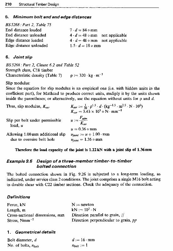
210 Structural Timber Design
5. ~ i n i m ~ m bolt end and edge distances
BS5268 : Part 2, Table 75 End distance loaded 7 - d = 8 4 o m m End distance unloaded 4 + d = 48 o mm not applicable Edge distance loaded 4 - d = 48 o mm not applicable Edge distance unloaded 1 . 5 . d = l 8 0 m m
6. Joint slip
BS5268 : Part 2, Clause 6.2 and Table 52 Strength class, Cl8 timber Characteristic density (Table 7 ) p := 320 . kg m"3
Slip modulus: Since the equation for slip modulus is an empirical one (i.e. with hidden units in the coefficient part), for Mathcad to produce correct units, muliply it by the units shown inside the parentheses; or alternatively, use the equation without units for p and d.
Thus, slip modulus, K,,, K,,, := h. p1.5 . d . (kg"5 . m2.5 . N . 106) Kser = 3.43 X lo3 o N * mm-'
Slip per bolt under permissible U := - r;,,, &er load, U
U = 0.36 o mm Allowing 1 .OO mm additional slip Ujoint := U + 1 .OO mm
due to oversize bolt hole Ujoint = 1.36 o mm
Therefore the load capacity of the joint is 1.22 kN with a joint slip of 1.36mm
Example 9.6 Design of a three-member timber-to-timber bolted connection
The bolted connection shown in Fig. 9.26 is subjected to a long-term loading, as indicated, under service class 2 conditions. The joint comprises a single M16 bolt acting in double shear with C22 timber sections. Check the adequacy of the connection.
Definitions
Force, kN N :=newton Length, m kN := l o 3 . N Cross-sectional dimensions, mm Direction parallel to grain, // Stress, Nmm-2 Direction perpendicular to grain, pp
1 . Geometrical details
Bolt diameter, d NO. O f bolts, nbolt

Design of Timber Connections 211
5.2 kN
5.8 kN Rafter members: \r, ,/'k" 2 of 35 x 194 mm C22 timber
72 x 194 m C22 timber I 2.63 W
Fig. 9.26 Bolted connection (Example 9.6).
Side member thickness touter := 35 * mm Inner member thickness tinner := 72 * mm Check adequacy o f the section tinner = 72 0 mm > 2 * touter = 70 0 mm okay
Distance from loaded edge to he := 194. mm
2 furthest fastener he = 97 o mm
2. Basic vafues
BS5268 : Part 2, Clause 6.6.4 and Table 70 The support reaction acting on the ceiling tie makes the load in the rafter act parallel to grain, and in the ceiling tie to act at 27" to grain direction. Therefore Hankinson's equation should be used to determine the appropriate basic shear load values.
Strength class, C22 timber (Table 70) For 35 mm outer members FraYter.1 := 3.09 kN (rafters), long-term load parallel to the grain for a M16 bolt For 72mm inner member (ceiling tie) corresponding to 72/2 = 36 mm outer members for a M16 bolt:
long-term load parallel to Ftje.l := 3.18 kN
long-term load perpendicular Ftie.pp := 2.64 kN grain, by interpolation
to grain, by interpolation

21 2 Structural Timber Design
For load at angle a where Ftie := Ftie.8 Ftie.pp
n Ftie.8 * + Ftie.pp * COS(CX)~ a := 27.-
180 Ftie = 3.05 o kN (3) Grade shear stress for C22 1cg.8 := 0.71 N mm-2
timber (Table 7)
3. ~odification factors
BS5268 : Part 2, Clause 6.6 Timber-to-timb,er connection, &6 := 1
Moisture content, K56, service K56 := 1
No. of bolts in one line, K57 := 1
Service class 2 (K2, Table 13) K2 := 1 Load duration, long-term K3 := 1
Load sharing (K8, Clause 2.9) K8 := 1
K46 does not apply
class 2
n = l, K5,
(K3? Table 14)
4. ~ e r ~ i s s i ~ l ~ loads
(1) For rafter: Permissible load per Fadm.rafter := Fra8er.l k ; 6 ' K56 * K57
shear plane Fadm.mafter = 3-09 0 UJ 5.80 * kN
2 actual load (per shear plane) Prafter :=
Prafter = 2 -9 0 kN Satisfactory
(2) For ceiling tie: permissible load per Fadmetie := Ffie * &6 K56 ' K57
shear plane Fah. t i e 3.05 o kN 5.20 * kN
2 actual load (per shear plane) Prafter :=
Prafter = 2.6 o kN Satisfactory
(3) Shear stress in jointed timber BS 5268 : Part 2, Clause 6.1 and Figure 6 Permissible shear stress zadm Zg.// * K2 K3 Kg
Permissible shear force vu* .- S-" 2. 3 Z a h * he * tinner
> 2.63 kN Satisfactory
Z a h = 0.71 o N mm-2
V a h =L 3.31 0 kN

Design of Timber Connections
BS5268 : Part 2, Table 75 For rafter: end distance loaded end distance unloaded edge distance loaded edge distance unloaded For ceiling tie: end distance loaded end distance unloaded edge distance loaded edge distance unloaded
7 d = 1 12 o mm not applicable 4 - d = 6 4 o m m 4 d = 64 o mm not applicable 1 .5 .d=24omm
7 . d = 1120mm 4 . d = 64 o mm not applicable 4 . d = 6 4 o m m 1.5.d= 24omm
Therefore the connec~on with ~ N ~ u ~ edge and end distances detailed above will be ad~uate
esign of a t~ree-mem~er s t~ef - to - t im~~r ~ ~ f t e ~ moment connection
The bolted connection shown in Fig. 9.27 is subjected to a long-term eccentric load of 12.5 kN as indicated. The joint comprises two 4mm thick steel side-plates and an inner timber member in strength class C22 joined together using eight M12 bolts under service class 2 conditions. Check the adequacy of the connection.
Two 4 mm steel side-plates Inner member: ( timber
Fig. 9.27 Eccentric loaded connection (Example 9.7)).

214 Structural Timber Design
Force, kN Length, m Cross-sectional dimensions, mm Stress, Nmm-2
1 . Geometrical details
Bolt diameter, d
Bolting pattern: horizontal spacing, x vertical spacing, y Side member thickness
(Clause 6.6.5.1) Inner member thickness Distance from loaded edge to
NO. of bolts, nbolt
furthest fastener
2. lied loading
Applied vertical load, P Eccentricity, ep No applied horizontal load, H Eccentricity will induce a
moment of M and a shear force of V at C, the centre of geometry of the connection
Distance from C to each bolt, r
Sum of squares of distances from C to each bolt, J = r;!
Force acting on furthest bolt (i.e. bolt a) due to applied moment M
Force acting on bolt a due to applied shear force V
N :=newton
Direction parallel to grain, // Direction perpendicular to grain, pp
k~ := 103 N
d:= 12.mm nbolt := 8
x := 90 mm y := 85 -mm tsteel := 4 mm > 2.5mm or 0.3 d = 3.6 o mm
okay := 72 mm
h e : = 2 9 4 . m - 6 2 * m m he = 232 o mm
P := 12.5 * kN ep := 45 a mm
M : = P . e p M=0.56okN-m V : = P Y = 12.5okN
H:=O*kN
ra := ~xT ra = 123.79 o mm rb := x rf := x
rd := y rh := y rc := ra re := ra rg := ra
J : = 4 . r ~ + 2 * r ~ + 2 . r ~ J= 9.2 X 1040mm2

Design of Timber Connections 21 5
Force acting on bolt a due to applied horizontal load H = 0
For the rectangular fastener pattern, the total force on bolt a is given by
This force is acting at an angle o f a to grain of timber, where
F : = [ (F.+ X J(x2 + 3 )
' Fa.M
F = 2.18 o kN
a = 76.18 o deg
3. Basic load vaiues
BS5268: Part 2, Clause 6.6.4 and Table 70 72 mm inner member corresponding to 72/2 = 36 mm outer members for a M12 bolt:
Long-term load // to grain, by interpolation
Long-term load perpendiuclar to grain, by interpolation
For load acting at angle a
Grade shear stress for C22 timber (Table 7)
Fpp := 2.105 * kN
F1 * FPP F := F1 * sin(a)2 + Fpp COS(^)^
F=2.12okN ~ ~ - 1 := 0.71 N mmm2
4. ~odification factors
BS.5268 : Part 2, Clause 6.6 Steel-to-timber connection &6 := 1.25
Moisture content, K56, service K56 := l
No. o f bolts in one line, K57 := 1
Service class 2 (KZ, Table 13) K2 := l Load duration, long-term K3 := 1
Load sharing (Kg, Clause 2.9) K8 := I
(&fit Clause 6.6.5.1)
class 2
n = 3,
(K3, Table 14)

BS5268 : Part 2, Clause 6.6.6 Permissible load per shear plane Fadm := F . &6 - K56 K57
Number of shear planes nshear := 2 Permissible load for bolt Fadm.bolt := Fadm * nshear
Fadm = 2.64 o kN
Fadm.bolt = 5 -29 0 kN Satisfactory
Shear stress in jointed timber: BS 5268 : Part 2, Clause 6.1 and Figure 6 Permissible shear stress
Permissible shear force
Hence the timber section can sustain an applied shear force at the connection of Fadm.y
6. ~ i n i ~ u m bolt spacings
BS5268 : Part 2, Table 75 end distance loaded end distance unloaded edge distance loaded edge distance unloaded spacing parallel to grain spacing perpendicular to grain
7 . d = 84 o mm not applicable 4 . d = 48 o mm not applicable 4 . d = 48 o mm 56 mm provided okay 1.5 . d = 18 o mm not applicable 5 . d = 60 o mm < 78 mm provided okay 4 . d = 48 o mm 73 mm provided okay
Therefore the connection as detailed above is adequate
Design of an eave joint of a roof truss is required. The joint is to comprise two Finnish conifer plywood (9mm thick, 7-ply) gussets, one on each side, glued to rafter and ceiling tie members both in Cl8 timber under service class 2 conditions and is subjected to medium-term loading, as shown in Fig. 9.28. Determine the contact areas required for the rafter and tie member where bonding pressure is generated by nails.
Force, kN N := newton Length, m k~ := 103. N Cross-sectional dimensions, mm Direction parallel to grain, // Stress, Nmmm2 Direction perpendicular to grain, pp
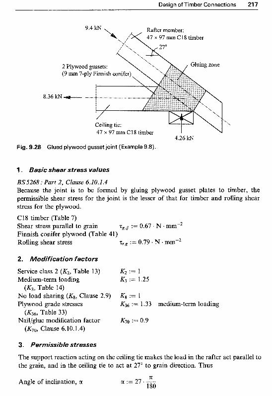
Design of Timber Connections
8.36
2 Plywood gussets: (9 m 7-ply Finnish conife
zone
I l I
l
/ Ceiling tie: 47 x 97 m C18 timber
4.26 ICN Fig. Glued plywood gusset joint (Example 9.8).
ear s t r ~ s s val~es
33.7268 : Part 2, Clause 6.10.1.4 Because the joint is to be formed by gluing plywood gusset plates to timber, the permissible shear stress for the joint is the lesser of that for timber and rolling shear stress for the plywood. C 18 timber (Table 7) Shear stress parallel to grain zg.i := 0.67 . N mm-2 Finnish conifer plywood (Table 41) Rolling shear stress z,.g := 0.79 I N a mmm2
Service class 2 (KZ, Table 13) K2 := 1 Med ium- te~ loading K3 := 1.25
No load sharing (Kg, Clause 2.9) Kg := 1 Plywood grade stresses K36 := 1.33 medium-term loading
Naillglue modification factor K70 :== 0.9
(K3, Table 14)
Table 33)
(K70, Clause 6.10.1.4)
stresses
The support reaction acting on the ceiling tie makes the load in the rafter act parallel to the grain, and in the ceiling tie to act at 27" to grain direction. Thus
Angle of inclination, a K a : = 2 7 * - - - 180

21 8 Structural Timber Desian
Therefore the shear stress for timber is limiting for both the rafter and tie contact faces.
(1) For rafter load in rafter, Prafter Prafter := 9.4 * kN
required contact area on Prafter
2 * Tah.rafter Arafter :=
Arafter = 6.24 X l O3 0 mm2 each side,
(2) For ceiling tie load in tie, Pt ie Pi, := 8.36 kN
required contact area on Ptie
2 * Tah. t i e
At ie = 7.97 X io3 o mm2
Atie := each side, At ie
te
Eurocodes are civil and structural engineering design standards, that are published by the European Committee for Standardisation (CEN), for use in all member countries. They are designed to provide a framework for harmonised specifications for use in the construction industry. At present there are nine Eurocodes which are published as European pre-standard, or ENV, to serve as an alternative to the existing national codes in each country. They are as follows:
EC1 EC2 EC3 EC4 EC5 EC6 EC7 EC8 EC9
Basis of design and actions on structures Design of concrete structures Design of steel structures Design of composite steel and concrete structures Design of timber structures Design of masonry structures Geotechnical design Design of structures in seismic regions Design of aluminium structures.
The draft edition of Eurocode 5 : Part 1.1 for timber structures was published in the UK in late 1994 as DD ENV 1995- 1 - 1 : 1994, in conjunction with a National Application Document (NAD) for the United Kingdom which contains supplementary information to facilitate its use nationally during the ENV period. The publication of the definitive EN EC5 is planned for around 2001 and is expected to be used in parallel with BS 5268 until the year 2005 (overlap period). At the transition, BS 5268 will not be withdrawn but is likely to be termed ‘obsolete’. In this state it would not be updated or amended and as such would become less usable with time.
In general, DD ENV 1995-1-1 : 1994 (i.e. EC5) contains all the rules neces- sary for the design of timber structures, but unlike BS 5268 : Part 2 it does not provide material properties and other necessary design information.
21

Structural Timber Design
Such information is available in supporting European standards, for example, BS EN 338 : 1995 which contains the material properties, such as bending and shear strength, etc., for the 15 strength classes of timber (i.e. C14 to D70). Therefore to design with EC5 it is necessary to have several additional reference documents to hand.
The design of timber structures is related to Part 1.1 of EC5 and is based on limit states design philosophy which means that the overall performance of structures should satisfy two basic requirements. The first is ultimate limit states (i.e. safety), usually expressed in terns of load-bearing capacity, and the second is s~rviceability limit states (i.e. deformation and vibration limits), which refers to the ability of a structural system and its elements to perform satisfactorily in normal use.'
In general, it is well understood that the violation of ultimate limit states, i.e. safety criteria, may cause substantial damage and risk to human life, whereas exceeding the serviceability limits, i.e. excessive deformation andlor vibration, rarely leads to such severe consequences. However, while this may suggest that serviceability is relatively unimportant, in practice it is often the key element to ensuring an economical and trouble-free structure.
Generally, it is necessary to check that design criteria for both ultimate limit states and serviceability limit states are satisfied. or checking ulti- mate limit states, the characteristic values of both the loads and the material properties are modified by specified partial safety factors that reflect the reliability of the values that they modify. These factors increase the values of the loads and decrease the values of the material properties. To check serviceability limit states, EC5 requires that both instantaneous and time- dependent (creep) deflections are calculated and, in addition, designers are required to demonstrate that vibration in floors is not excessive.
The characteristic values are generally fifth percentile values derived directly from a statistical analysis of laboratory test results. The character- istic strength is the value below which the strength lies in only a small percentages of cases (not more than 5%), and the characteristic load is the value above which the load lies in only a small percentage of cases.
Throughout EC5, depending on the character of the individual clauses, a distinction is made between princ~les and application rules. statements, definitions, requirements or analytical models for which no alternative is permitted unless specifically stated (principles are preceded by the letter P), and application rules are generally recognised rules that follow the principles and satisfy their requirements.
In EC5, in common with other Eurocodes, decimal points are displayed as commas (so 1.2 is displayed as 1,2).

Design to Eurocode 5
artial safety factors for actions in building structures for persistent and transient design situations (Table 2.3.3.1, EC5) -~ -
Permanent actions Variable actions Y Q
YG
One with its Others with their characteristic value combination value
Normal partial coeficients Favourable effect 1 .o 0 Unfavourable effect 1.35 1.5
Reduced partial coeficients Favourable effect 1 .o 0 Unfavourable effect 1.2 1.35
0 1.5
0 1.35
Actions is the Eurocode terminology used to define (i) direct loads (forces) applied to the structures, and (ii) indirect forces due to imposed defor- mations, such as temperature effects or settlement. Actions are covered in Chapter 2 of EC5.
ermanent actions, denoted by the letter C, are all the dead loads acting on the structure, including the self-weight, finishes and fixtures. Variable actions, denoted by the letter Q, are the imposed, wind and snow loads.
ance on obtaining the characteristic values of actions is given in asis of design and actions on structures. The characteristic values for
actions are modified by partial coefficients, y to take account of safety factors, load combinations, etc.
Therefore the design values of actions, Fd, are obtained by multiplying the characte~stic actions for permanent, Gk, and/or variable, relevant partial coefficients, yG and yQ, as given in Table 2.3.3.1 of EC5, (reproduced here as Table 10.1). Thus:
(10.1)
Chapter 3 of ENV 1995-1-1 (EC5 : Part 1.1) deals with the material prop- erties and defines the characteristic strength, stianess and density values of solid timber sections for strength classes C14 to D70. EC5, unlike
S 5268 : Part 2 : 1996, does not contain the material properties values and, as mentioned earlier, this i n fo~a t ion can be found in a supporting standard i.e. in Table 1 of S EN 338 : 1995 (re oduced here as Table 10.2). A com- parison of this table with Table 7 o S 5268 : Part 2 : 1996 (see Table 2.3)

222 Structural Tim
ber D
esign
? 099
00
-0
00
-d
.N
.-.I
P-m
-P-00
-?c
?"
F?
?
ow
mW00
P-0
00
trtoo
-?"I?
m-d
. P
-*
oo
::i

Design to Eurocode 5 223
highlights the difference between the characteristic values and the grade stress values familiar to users of BS 5268. The characteristic values, which are generally fifth percentile values, are considerably higher than the BS 5268 grade values which have been reduced for long-term duration and already include relevant safety factors. In addition, BSEN338 does not include grade TR26 timber. This is an extra grade which has been included in BS 5268 only.
The characteristic strength values given in Table 1 of BS EN 338 (see Table 10.2) are measured in specimens of certain dimensions conditioned at 20°C and 65% relative humidity, in tests lasting approximately five minutes; and therefore they are applicable for such loading and service conditions. For other loading and service conditions, the characteristic values should be modified using relevant modification factors, which are described later.
Clause 2.2.3-2 of EC5 specifies that the design value, Xd, of a material property is calculated from its characteristic value, x,, using the following equation:
for strength properties,
(10.2a)
for stiffness properties, xk
x d = - (10.2b) Y i u
where: yM is the partial safety factor for material property and its values are
given in Table 2.3.3.2 of EC5 (reproduced here as Table 10.3) kmod is the modification factor for service class and duration of load. Modi-
fication factor kmod takes into account five different load-duration classes: permanent, long-term, medium-term, short-term and instan- taneous, relating to service classes of 1, 2 and 3 as defined in Clauses 3.1.5-3.1.7 of EC5. A summary of Clause 3.1.5 and Tables 3.1.6 and 3.1.7 of EC5 is reproduced here as Table 10.4. For metal components, kmod should be taken as 1 , i.e. kmod= 1.0.
The characteristic strength values given in Table 1 of BS EN 338, see Table 10.2, are related to a depth in bending and width in tension of 15Omm. For depth in bending or width in tension of solid timber, h, less than 150 mm, EC5 in Clause 3.2.2(5) recommends that the characteristic values for fm,k andft,O,k may be increased by the factor kh where:
kh = the lesser of ( k h = (yr.’ and kh = 1.3 ) (10.3)
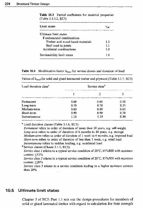
Structural Timber Design
able 10.3 Partial coefficients for material properties (Table 2.3.3.2, EC5)
Limit states Y M
Ultimate limit states Fundamental combinations
Timber and wood-based materials 1.3 Steel used in joints 1.1
Accidental combinations 1 .o
Serviceability limit states l .o
Table 10.4 Modification factor kmod for service classes and duration of load
Values of kmod for solid and glued laminated timber and plywood (Table 3.1.7, EC5)
Load duration classa Service classb
1 2 3
Permanent Long-term Medium-term Short-term Instantaneous
0.60 0.60 0.50 0.70 0.70 0.55 0.80 0.80 0.65 0.90 0.90 0.70 1.10 1.10 0.90
a Load duration classes (Table 3.1.6, EC5): Permanent refers to order of duration of more than 10 years, e.g. self-weight Long-term refers to order of duration of 6 months to 10 years, e.g. storage ~ e ~ i u m - t e r m refers to order of duration of 1 week to 6 months, e.g. imposed load Short-term refers to order of duration of less than 1 week, e.g. wind load ~ n s t u n t u n e o ~ refers to sudden loading, e.g. accidental load Service classes (Clause 3.1 S , EC5): Service cZuss I relates to a typical service condition of 20°C, 650/RH with moisture content 5 12% Service cluss 2 relates to a typical service condition of 20°C, 85%RH with moisture content 520% Service cluss 3 relates to a service condition leading to a higher moisture content than 20%
Chapter 5 of EC5 : Part 1.1 sets out the design procedures for members of solid or glued laminated timber with regard to calculation for their strength

Design to Eurocode 5 225
properties (ultimate limit states) and treats solid and glued laminated members in the same way. Design procedures relevant to flexural and axially loaded members and dowel-type joints are described below.
embers should be designed so that the following conditions are satisfied:
+ km om,z ld 5 1 fm,yld fmlzld
(10.4a)
(1 0.4b)
where: k m is the modification factor for combined bending stress,
detailed in Clause 5.1.6(2) of EC5 as: for rectangular sections, k m = 0.7 for other cross-sections, km = 1 .O
and z-z, as shown in Fig. 10.1 C T , , ~ , ~ & ums,d are the design bending stresses about the principal axes y-y
where: My,d== design bending moment about y-y axis, and
bh2 W - - is the appropriate section modulus '" 6
where: = design bending moment about z-z axis, and
hb2 6 Cy, = - is the appropriate section modulus
Y
Fig. 10.1

226 Structural Timber Design
fm,y.d fm,z,d are the design bending strengths about y-y and Z-z axes kmod * kh * kcrit * kls ‘ fm,k
fm,y/z,d (10.5) Y M
where: is the modification factor for load duration and service classes as given in Table 3.1.7 of EC5, see Table 10.4, is the modification factor for bending depth (Clause 3.2.2), is the mod~cation factor for reducing bending strength of a beam where there is a possibility of lateral buckling. For a beam which is laterally restrained throughout the length of its compression edge and its ends are prevented from torsional rotation, kcrir = 1.0. For other conditions, Clause 5.2.2 of ECS and Clause 6.5 of the UK NAD recommend the following: (1) Calculation of the critical bending stress, om,crit , as given by the
following equation for a rectangular section of breadth b and depth h:
(10.6)
The effective length Lef is governed by the degree of restraint against lateral deflection, rotation in plan and twisting, and may be considered as: Lef= 0.71; for a beam fully restrained against rotation in plan
Lef= 0.85L for a beam partially restrained against rotation in
Lef= 1.2L for a beam partially restrained against twisting at
at both ends,
plan at both ends or fully restrained at one end,
one or both ends. (2) Calculation of the relative slenderness for bending as:
(10.7)
(3) The value of kcrir is then determined from: kcrit = 1 for hre1.m 5 0.75 kcrit = 1.56 - 0.75hrel,m for 0.75 < hrel,m 5 1.40 kcrit = 1/’&,m for l .40 < hre1,m
is the modification factor for load-sharing systems. See Clause 5.4.6 of EC5 for details of the conditions outlined for load sharing systems
is the characteristic bending strength (Table 1, BS EN 338 : 1995), see Table 10.2, is the partial coefficient for material properties (Table 2.3.3.2, EC5), see Table 10.3, and is the 5%tile modulus of elasticity (Table 1, BS EN 338 : 1995), see Table 10.2.
(h, = 1 *U,

Design to Eurocode 5 227
Members should be designed so that the following condition is satisfied (Clause 5. l .7, EC5):
z d 5 fV,d (10.8)
where: zd is the design shear stress, and for beams with a rectangular cross-
section, is given by:
(10.9)
where Vd is the design shear force (maximum reaction) and A is the cross-sectional area, where A = bh. For beams with a notched end A = bh,, see Fig. 10.2.
fv,d is the design shear strength, which is given by:
h o d ' kls * k V ' fV,k
Y M fV,d = (10.10)
where: f V,k
Y M
kmod
klS
kV
is the characteristic shear strength (Table 1, BS EN 338 : 1995), is the partial coeficient for material properties, (Table 2.3.3.2, EC9, is the modification factor for load duration and service classes (Table 3.1.7, EC5), is the modification factor for load-sharing systems (kh = 1.1) (Clause 5.4.6, EC5), is the modification factor for shear in members with notched ends, see Fig. 10.2, where, for beams with no notched ends, kv= 1.0 for beams notched at the unloaded side, kV= 1 .O for beams notched at the loaded side,
+ l !+
h e / l l I
(a) Notch on loaded side (b) Notch on unloaded side
Fig. 10.2 End-notched beams (DD ENV 1995-1 -1 : 1994).
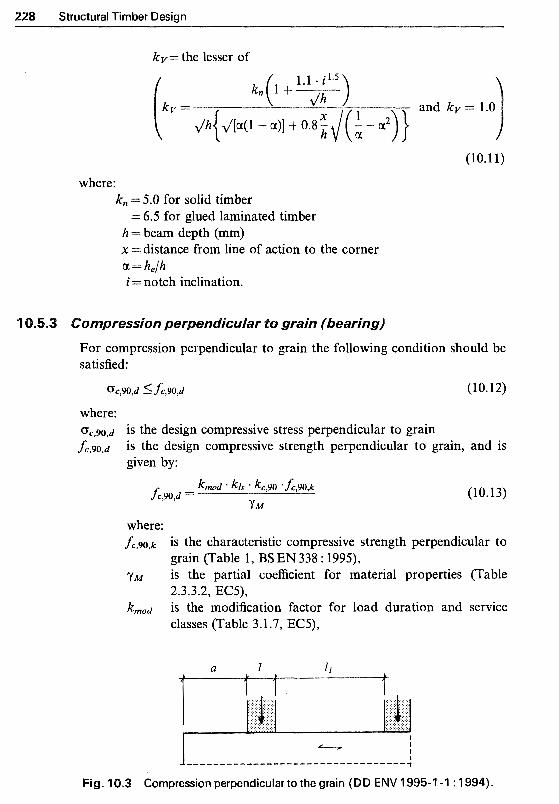
2 2 ~ Structural Timber Design
kV= the lesser of
(10.11)
where: kn = 5.0 for solid timber
h = beam depth (mm) x =distance from line of action to the corner 01 = h,/h i = notch inclination.
= 6.5 for glued laminated timber
oc,90,d 5 fc,90,d (10.12)
where: L,go,k is the characteristic compressive strength perpendicular to
yM is the partial coefficient for material properties (Table
kmod is the modification factor for load duration and service
grain (Table 1, BS EN 338 : 1995),
2.3.3.2, EC5),
classes (Table 3.1.7, EC5),
I I I
l """""""""""""" """I Fig. 10.3 Compression perpendicular to the grain (DD ENV 1995-1 -1 : 1994).

Design to Eurocode 5 229
kls is the modification factor for load-sharing systems, i.e. kls = l . 1 , (Clause 5.4.6, EC5), is the modification factor for bearing length, which takes into account that the load can be increased if the loaded length, l, is short, see Fig. 10.3. The values of are shown in Table 5.1.5 of EC5 (reproduced here as Table 10.5).
Table 10.5 Values of (Table 5.1 S , EC5)
a> l o o m a< 100 mm
I> 150mm 1 1 l 1 5 0 m > 1 > 1 5 m 1 1 +(l50-2) / 170 1 +a (150-1) / 17000 15mm>Z l 1.8 1 + up25
o~pression or tension parallel to grain
For members subjected to axial compression only, the following condition should be satisfied provided there is no tendency for buckling to occur (Clause 5.1.4, EC5):
oc,O,d 5 fc,O,d (10.14) where: o,,O,d is the design compressive stress parallel to grain, and is given by:
(10.15)
where N d is the design axial load and A is the cross-sectional area fc,O,d is the design compressive strength parallel to grain, and is given by:
(10.16)
where: fc,O,k is the characteristic compressive strength parallel to grain
y M is the partial coefficient for material properties (Table 2.3.3.2,
kmod is the modification factor for load duration and service classes
k l , is the modification factor for load-sharing systems, i.e.
(Table 1, BS EN 338 : 1995),
EC5),
(Table 3.1.7, EC5), and
kts = 1.1 , (Clause 5.4.6, ECS).
For members subjected to axial tension a similar condition and procedure apply (Clause 5.1.2, EC5).
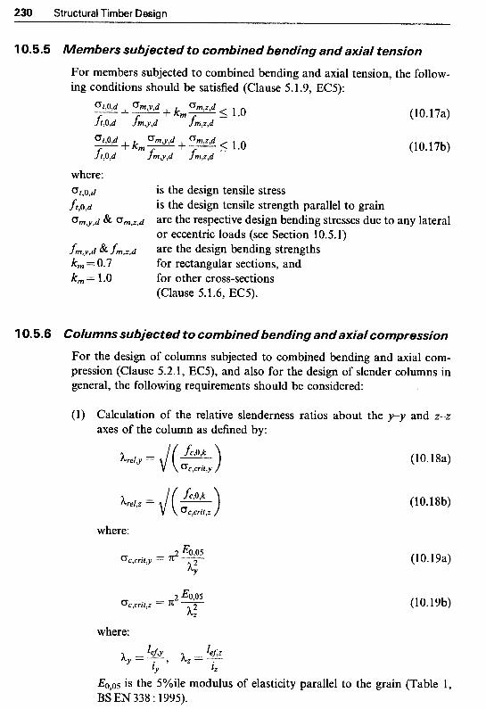
230 Structural Timber Design
10.5.5 Members subjected to combinedbending and axia/ tension
For members subjected to combined bending and axial tension, the follow- ing conditions should be satisfied (Clause 5.1.9, EC5):
(10.17a)
(10.17b)
where: Ot,O,d is the design tensile stress
h,O,d is the design tensile strength parallel to grain (3,,y,d & (Tm,,,d are the respective design bending stresses due to any lateral
fm,y,d & fm,z,d are the design bending strengths or eccentric loads (see Section 10.5.1)
k m = 0.7 for rectangular sections, and k m = 1.0 for other cross-sections
(Clause 5.1.6, EC5).
1 0.5.6 Co/umns subjected to combined bending and axiaf compression
For the design of columns subjected to combined bending and axial com- pression (Clause 5.2.1, EC5), and also for the design of slender columns in general, the following requirements should be considered:
(l) Calculation of the relative slenderness ratios about the p-. and 2-2
axes of the column as defined by:
where:
where:
(10.18a)
(10.18b)
(10.19a)
(10.19b)
EO,os is the 5%ile modulus of elasticity parallel to the grain (Table 1, BS EN 338 : 1995).

Design to Eurocode 5 231
(2) For both hrel,y 5 0.5 and hrel,z 5 0.5, the stresses should satisfy the following conditions:
( % ) 2 + Z + k m - fm,z,d om,z,d 5 1.0
5 1.0
( 10.20a)
(1 0.20b)
where: oc,O,d
fc,O,d
omy,d om,z ,d
fm,y.d & fm,z,d km = 0.7 km = 1.0
is the design compressive stress is the design compressive strength parallel to grain are the respective design bending stresses due to any lateral or eccentric loads (see Section 10.5.1) are the design bending strengths for rectangular sections, and for other cross-sections (Clause 5.1.6, EC5).
(3) For all other cases, i.e. hre1,y > 0.5 and/or Are/,= > 0.5, the stresses should satisfy the following conditions:
oc,O,d om,z,d +- +km% 5 1.0 ‘fc,O,d fm,z,d fm,y,d
(10.21a)
(10.21b)
where kc,, and kc,z are modification factors of compression members and are given by:
1 k c , , = (similarly for kc,z)
k y + J(G - h;el,y)’ (10.22a)
ky = 0.5(1 + Pc(hrel,y - 0.5) + (similarly for k,) (10.22b) where: pc= 0.2 for solid timber, and pc = 0.1 for glued laminated timber.
owel-type fastener joints
EC5, Chapter 6 deals with the ultimate limit states design criteria for joints made with dowel-type fasteners, such as nails, screws, bolts and dowels, but does not give any information regarding connectored-type joints, i.e. toothed plates, split-rings, etc.
EC5 provides formulae, based on Johansen’s equations, to determine the load-carrying capacity of timber-to-timber, panel-to-timber and steel-to- timber joints, reflecting all possible failure modes. Load-carrying capacity formulae for timber-to-timber and panel-to-timber joints, with reference to their failure modes, are compiled in Table 10.6, and for steel-to-timber joints in Table 10.7.

232 Structural Timber Design
Table 10.6 Load-carrying capacity of timber-to-timber and panel-to-timber joints (based on Clause 6.2.1, EC5)
Joints in single shear
Failure modes ti" t2
carrying capacity per dowel, Rd, is the lesser of:
Rd,b =fh,l,d * t2 * d P
Rd,c
-P(I +~)]
(10.23a) (10.23b)
(10.23~)
(10.23d)
(1 0.230
Joints in double shear
Failure modes
(10.23g)
(1 0.23h)
(10.23j)
(10.23k)

Design to Eurocode 5 233
Table 10.7 Load-carrying capacity of steel-to-timber joints (based on Clause 6.2.2, EC5)
Joints in single shear
Failure modes
Design load- (i) Thin steel plate (tsteel 5 0.5 d) carrying Rd,a = 0.4fh,l,d * tl * d capacity per Rd,b = 1-1J(2Myld 'fh,l,d d ) dowel, Rd, is the lesser of: (ii) Thick steel plate (fsteel >. d)
(10.24a) (10.24b)
(10.24c)
(1 0.24d)
Joints in double shear
Design load- (i) Steel plate as the centre member carrying Rd,e = I.Ifh,l,d * tl * d capacity per dowel per &,f = l-lfh,l,d * tl * d shear plane Rd, is the Rd,g = 1.54(2My,d 'fh,l,d d) lesser of: (ii) Thin steel side plates (tStMl 5 0.5d)
&,h = 0*5f,2,d * t2 d &,j = 1.1 J(2My1d 'fh12,d * d )
(iii) Thick steel side plates (tsteel >d) Rd,k = 0.5fhh,2,d * t2 ' d Rd,l = 1.5J(2My1d 'fh,2,d d)
(10.24e)
(10.24f)
(10.24g)
(10.24h) (10.24j)
(10.24k) (10.241)
As an example, for a two-member timber-to-timber joint there are six possible modes of failure. One or both of the timber members may fail, or the fastener may fail in one or both timber members, see failure modes (a) to (f) in Table 10.6. EC5 therefore provides six different formulae to calculate

234 Structural Timber Design
the failure load for each mode and recommends that the lowest value is taken as the failure load of the connection.
Therefore the design load-carrying capacity, R d , for a fastener in single shear in a timber-to-timber joint is given as the lesser of to (reproduced below from Table 10.6):
R d , a = h , l , d * tl * d (l 0.23a)
R d , b = h , l , d * t2 d . P (10.23b)
- P ( 1 + ~ ) ] (10.23~)
(10.23d)
(10.23f)
where:
fh,i,d 432 fh,2,d are the design embedding strengths in tl and t2 and are tl 432 t 2 are timber or board thickness or penetration
given by:
f , , kmod, l h, l ,k
h i d = and h , 2 , d = kmod,2fh,2,k (10.25) Y M Y M
P d
where, f h , l , k and fh,2,k are the characteristic embedding strengths in tl and t2. The characteristic embedding strength values for different connection types are extracted from Clauses 6.3-6.7 of EC5 and are compiled in Table 10.8. As an example, for a nailed timber-to-timber joint with predrilled holes, fh,k = 0.082(1 - O.Old)pk in N/mm2 (Clause 6.3.1.2(1)). Values of the modification factor, kmod, are given in Table 3.1.7 and the values of yM are given in Table 2.3.3.2 of EC5.
is the fastener diameter is the fastener yield moment and is given by:
= h , 2 , d / f h , 1 ,d
(10.26)
where M’,k is the characteristic value for dowel yield moment.
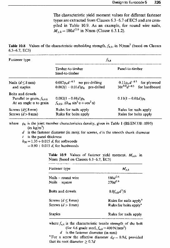
Design to Eurocode 5 235
The characteristic yield moment values for different fastener types are extracted from Clauses 6.3-6.7 of EC5 and are com- piled in Table 10.9. As an example, for round wire nails, M y , k = 1 80d2.6 in Nmm (Clause 6.3.1.2).
Table 10.8 Values of the characteristic embedding strength, fh,k, in N/mm2 (based on Clauses 6.3-6.7, EC5)
Fastener type h , k
Timber-to-timber Steel-to-timber
Panel-to-timber
Nails (d 5 8 mm) 0.082p&0.3 no pre-drilling 0. l l p,4°-3 for plywood and staples 0.082(1 - O.Old)pk pre-drilled 30t0.6d-0.3 for hardboard
Bolts and dowels Parallel to grain, fh,)& 0.082(1 - 0.Old)pk 0.11(1 "O.Old)pk At an angle a to grain h,O,k /(/cw sin2 a + cos2 a)
Screws (d< 8 mm) Rules for nails apply Screws (d > 8 mm) Rules for bolts apply
Rules for nails apply Rules for bolts apply
where pk is the joint member characteristics density, given in Table l (BS EN 338 : 1995) (in kg/m3)
d is the fastener diameter (in mm); for screws, d is the smooth shank diameter t is the panel thickness kg0 = l .35 + 0.01 5 d, for softwoods = 0.90 + 0.01 5 d, for hardwoods
Table 10.9 Values of fastener yield moment, kfy,k, in Nmm (based on Clauses 6.3-6.7, EC5)
Fastener type %,k
Nails - round wire Nails - square
Bolts and dowels
Screws (d 5 8mm) Screws (d > 8 mm)
Staples
1 80d2.6 270d2*6
Rules for nails applya Rules for bolts applya
Rules for nails apply
where fu,k is the characteristic tensile strength of the bolt (for 4.6 grade steel, fu,k = 400 N/mm2)
a For a screw the effective diameter def = 0.9d, provided that its root diameter 2 0.7d
d is the fastener diameter (in mm)
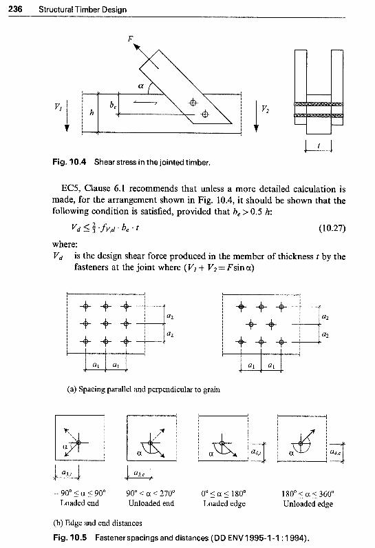
236 Structural Timber Design
F
"i 1 v2
~
Fig. 10.4 Shear stress in the jointed timber.
EC5, Clause 6.1 recommends that unless a more detailed calculation is made, for the arrangement shown in Fig. 10.4, it should be shown that the following condition is satisfied, provided that be > 0.5 h:
vd 5 $'fV,d'be* t (10.27)
where: vd is the design shear force produced in the member of thickness t by the
fasteners at the joint where (Vl + V'= Fsin a)
l I I
(a) Spacing parallel and perpendicular to grain
- 90' 5 cx 5 90" 90' a < 270" 0" 5 a 5 180' 180' 5 a 5 360" Loaded end Unloaded end Loaded edge Unloaded edge
(b) Edge and end distances
Fig. 10.5 Fastener spacings and distances (DD ENV 1995-1 -1 : 1994).

Design to Eurocode 5 237
n
VI
2
V A
I, %
%W

238 Structural Timber Design
be is the distance from the loaded edge to the furthest fastener fV,d is the design shear strength of timber member.
For nailed connections, EC5, Clause 6.3.1.2 recommends that there should be at least two nails in a joint, that smooth nails should have a pointside penetration of at least 8d, (6d for improved nails) and nails should be driven into pre-drilled holes in timber with a characteristic density of 500kg/m3 or more. The recommendations for minimum nail spacings and end distances are given in Table 6.3.1.2 of EC5 (reproduced here as Table 10.10).
For bolted connections, EC5, Clause 6.5.1.2 recommends that for more than six bolts in line with the load direction, the load-carrying capacity of the extra bolts should be reduced by one third, i.e. for n bolts, the effective number, nef, is nef = 6 + 2(n - 6)/3. The recommendations for minimum bolt and dowel spacings and end distances are given in Tables 6.5.1.2 and 6.6a of EC5 respectively (reproduced here as Table 10.1 1).
Chapter 6 of EC5 also provides formulae for calculating resistance to axial loading in nailed, screwed and bolted joints, see Clauses 6.3.2 and 6.3.3, 6.7.2 and 6.7.3 and 6.5.2 respectively. These cover withdrawal of the fastener from its head-side (pull-out), pulling through of the fastener head (pull-through), and also combined axial and lateral loading.
Table 10.11 Minimum bolt and dowel spacings and distances (based on Tables 6.5.1.2 and 6.6a, EC5)
Spacings and distances Bolts (see Fig. 10.5)
Dowels
Spacing parallel (al) (4 + 3lcos al)d Spacing perpendicular (az) 4d
(4 + 3lcos al)d 3d
Loaded end distance (a3J
Unloaded end distance (a3,=) -90" 5 01 5 90" 7d (but 280mm) 7d (but >80mm)
150" 5 a 5 210" 4d 3d 90" < a 150" and (1 + lilsin. al)d (but 2 4 4 qt61sin a1 (but 2 3 4 210" < a < 270"
Loaded edge distance (a4J
Unloaded edge distance (a4,=) 0" 5 a 5 180" (2 + 2lsin al)d (but 2 3 4 (2 + 2/sin al)d (but 2 3 4
all other values of a 3d 3d
where d= bolt or dowel diameter (in mm) a = angle of force to grain direction
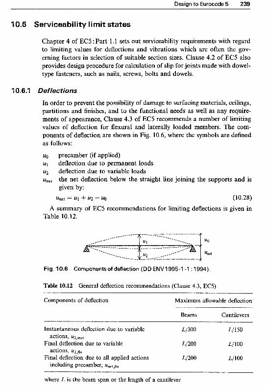
Design to Eurocode 5 239
ility limit states
Chapter 4 of EC5 : Part 1.1 sets out serviceability requirements with regard to limiting values for deflections and vibrations which are often the gov- erning factors in selection of suitable section sizes. Clause 4.2 of EC5 also provides design procedure for calculation of slip for joints made with dowel- type fasteners, such as nails, screws, bolts and dowels.
In order to prevent the possibility of damage to surfacing materials, ceilings, partitions and finishes, and to the functional needs as well as any require- ments of appearance, Clause 4.3 of EC5 recommends a number of limiting values of deflection for flexural and laterally loaded members. The com- ponents of deflection are shown in Fig. 10.6, where the symbols are defined as follows:
uo precamber (if applied) u1 deflection due to permanent loads 2.42 deflection due to variable loads unet the net deflection below the straight line joining the supports and is
given by: Unet = 4" U2 - U0 (10.28)
A summary of EC5 recommendations for limiting deflections is given in Table 10.112.
Fig. 10.6 Components of deflection (DD ENV 1995-1 -1 : 1994).
Table 10.12 General deflection recommendations (Clause 4.3, EC5)
Components of deflection Maximum allowable deflection
Beams Cantilevers
Instantaneous deflection due to variable L/300 L/150
Final deflection due to variable L/200 L/100
Final deflection due to all applied actions L/200 L/ 100
actions, u~~~~~
actions, u2$,,
including precamber,
where L is the beam span or the length of a cantilever

240 Structural Timber Design
Table 10.13 Values of kddfor solid and glued laminated timber and plywood and joints (based on Table 4.1, EC5)
Material/ Service classa Load duration classa
1 2 3
Solid and glued laminated timber
Permanent Long-term Medium-term Short-term
0.60 0.80 2.00 0.50 0.50 1 S O 0.25 0.25 0.75 0 .oo 0.00 0.30
Plywood
Permanent 0.80 1 .oo 2.50 Long-term 0.50 0.60 1.80 Medium-tern 0.25 0.30 0.90 Short-term 0.00 0.00 0.40
a Service and load duration classes are defined in Table 10.4
The UK NAD and EC5 recommend the following procedure for calcula- tion of the instantaneous and final deflections:
The instantaneous deflection of a solid timber member acting alone should be calculated using the appropriate 5%tile modulus of elast- icity, Eo,05 and/or 5% tile shear modulus, Go,o5, where G0,Os = .Eo,O5/16. The instantaneous deflection of a member made of two or more sections fastened together to act as a single member, a member in a load-sharing system, glulam and a composite-section member may be calculated using the mean elastic or shear moduli, i.e. Eo,,,,, and Gme,,. The final deflection at the end of the design life of a component, ufin, is calculated as:
u8n = ~inst(1 + kdef) (10.29)
where kdef is the modification factor which takes into account the increase in deformation with time due to the combined eEect of creep and moisture. The values of kd, , are given in Table 4.1 of EC5 (reproduced here as Table 10.13).
EC5, Clause 4.4.1 states that actions which are anticipated to occur frequently should not produce vibrations which might impair the function- ing of the structure or cause unacceptable discomfort to the users. Clauses

Design to Eurocode 5 241
4.4.2 and 4.4.3 of EC5 provide recommendations and detailed rules for limiting vibrations.
The UK NAD recommends that for residential IJK timber floors the requirements of EC5 can be met by ensuring that the total instantaneous deflection of the floor joists under load (i.e. U l , j m t + ~2,jmt) does not exceed 14mm or L /333, whichever is the lesser, where L is the span in mm.
C5, Clause 4.2 provides a design procedure for the calculation of slip for joints made with dowel-type fasteners, such as nails, screws, bolts and dowels. In general, the serviceability requirements are to ensure that any deformation caused by slip does not impair the satisfactory functioning of the structure with regard to strength, attached materials and appearance.
The design procedure for calculation of slip for joints made with dowel- type fasteners is summarised as follows:
(1) The instantaneous slip, uinst, in mm, is calculated as: Fser
kser for serviceability verification, UiWt = -
3 * Fd for strength verification, Uimt = - 2 * kser
(10.30a)
(10.30b)
where: Fser & Fd are the service load and design load, in N, per fastener per
shear plane
values are given in Table 4.2 of EC5 (reproduced here as Table 10.14).
kser is the instantaneous slip modulus, in N/mm, and its
f the characteristic densities of the two joined members (pk.1 and ~ k , ~ ) are different, then pk in formulae given in Table 4.2 of EC5 (see Table 10.14) should be calculated as:
Pk = J(Pk,l * Pk,2) (10.31)
(3) The final joint slip, u ~ i ~ , should be calculated as:
where kdef is the modification factor for deformation and is given in Table 4.1 of EC5. For a joint made from members with different creep properties (kdexl
and kdex2), the final joint slip should be calculated as:
Ufln = UinstJ[(1 + kdeS,1)(1 + kdef,Z>] (10.33)

242 Structural Timber Design
Table 10.14 Values of slip moduli k,,,, per fastener per shear plane (in N/mm) (Table 4.2, EC5)
Fastener type
Timber-to-timber Panel-to-timber Steel-to-timber
Bolts and dowels Screws Nails (pre-drilled)
pk5d
Nails (no pre-drilling) & pk5d0.8 Staples
where Pk is the joint member characteristics density, given in Table 1, BS EN 338 : 1995 (in kg/m3) d is the fastener diameter (in mm).
(4) For joints made with bolts, EC5 permits 1 mm oversize holes which should be added to joint slip values. Thus:
-&er
kSW Uinst,bolt = 1 - (1 0.34)
(10.35)
1. Timber Engineering - STEP I (1995) Centrum Hout, The Netherlands.
Timber Engineering - STEP 2 (1955) Centrum Hout, The Netherlands. Page, A.V. (1993) The new timber design Code : ECS. The Structural Engineer 71,
No. 20, 19 October.
e s i p of floor joists
A timber floor spanning 3.8 m centre to centre is to be designed using timber joists at 600 mm centres. The floor is subjected to an imposed load of 1.5 kN/m2 and carries a

Design to Eurocode 5 243
dead loading, excluding self-weight, of 0.30 kN/m2. Carry out design checks to show that a series of 44 mm x 200 mm deep sawn section timber in strength class C22 under service class l is suitable.
Section A-A Cross-section Fig. 10.7 Timber floor joists (Example 10.1 ).
Force, kN Length, m Cross-sectional dimensions, mm
1. ~ e o ~ e t r i ~ a f properties
Breadth of beam section, b Depth of beam section, h Span between support centres, L Bearing length, I Joist spacing, Js Cross-sectional area, A
Second moment of area about y-y axis, Iy
Section modulus about y-y axis, Wy
Stress, Nmm"2 N :=newton kN := lo3 N
b:=44+mm h := 200 mm L := 3.8 mm I := 75 mm Js := 600 mm A : = b . h A = 8.8 X lo3 0mm2
b h3 12 Iy := -
Iy = 2.93 x lo7 o mm4 b + h2 wy := - 6
W y = 2.93 x lo5 o mm3

2 Structural Timber Design
BSEN338 : 1995, Table l Characteristic bending strength Characteristic shear strength Characteristic compression
perpendicular to grain Mean modulus of elasticity //
to grain 5%tile modulus o f elasticity //
to grain Mean shear modulus Average density
3. PartiaJ safety factors
EC: Part 1.1, Table 2."33.1 Permanent actions Variable actions
EC: Part 1.1, Table 2.3,3.2 Material factor for timber
Applied dead load, DL Self-weight, Swt
Total characteristic permanent
Imposed load, ZL Characteristic variable (imposed)
Design action, F d
load/m length, G k
load/m length, e k
A. U l t i ~ a t e limit states
5 . Mo~jfjcatjon factors
Factor for medium-duration loading and service class 1 (kmod, Table 3. l .7)
Size factor (kh, Clause 3.2.2) for h > 150mm
&.O'j := 6.7 kN mm-2
Gm,,, := 0.63 * kN * mm-2 pmean := 410 * kg mm-3

Design to Eurocode 5 245
Load sharing applies (kls, Clause 5.4.6)
Lateral stability (kcrit, Clause 5.2.2):
ffective length, Lef for full restraint against rotation
Critical bending stress (NAD, Clause 6.5)
kls := 1.1
Relative slenderness for bending
Lateral instability factor
Bearing factor
Bearing length, I No overhang at beam ends, a Distance between bearings, II
(kc,90, Clause 5.1.5): I := 75 - mm a := 0-mm 21 := L - I zI = 3.73 x 103 mm
In order to make Mathcad accept the following empirical equation, the indicated units have been added.
Bearing factor a - (150 - mm - I ) kc.go := 1 + 17 000 * mm2 kc.90 = 1
Factor for shear in members kV := l for no notch with notched end (kv, Clause 5.1.7.2)
Design bending moment
Design bending stress
Design bending strength

246 Structural Timber Design
7. Shear strength
Design shear stress
Design shear strength
8. Bearing strength
Design bearing load
Design bearing stress
Design bearing strength
B. Serviceability limit states
Clause 4.3, EC5 For serviceability limit states
(Table 2.3.3.2, EG5)
Bending moment due to permanent loads, MG
Bending moment due to variable loads, MQ
(1) Instantaneous deflection: For bending and shear due
to permanent action, Gk, using equations (4.6) and (4.9)
0V.d = 0.53 O N * Illm"2 Kmod * kV Kls 'fV.k fV.d :=
Y M
fV.d = 1.62 o N mm-2 Shear strength satisfactory
Vd = 3.12 o kN
oc.9o.d = 0.94 O N * lllm-2 kmod * kc.90 kls 'fc.90.k fc.90.d :=
Y M fc.90.d = 3.45 o N mm-2 Bearing strength satisfactory
yM := 1.0
M G = 0.39 o kN m Qk L2
8 MQ := -

Design to Eurocode 5 247
For bending and shear due to variable action, Q k
Maximum allowable deflection due to variable action (Clause 4.3, EC5)
(2) Final deflection due to variable actions:
Modification factor for deformation, for medium-term under service class 1 (kde$ Table 4.1, EC5)
Maximum allowable deflection (Clause 4,3, EC5)
(3) Final deflection due to all actions (permanent and variable):
Maximum allowable deflection (Clause 4.3, EC5)
%.inst c U2.inst.adm Satisfactory
In general, for beams without precamber, it is not necessary to check ~ 2 . f i n as unet.fm is always greater.
I O . ~ibration
The UK NAD re: EC5 Clause 4.4.1
Total instantaneous deformations should be less than the lesser of
(& = 11.41 o mm and 14mm
Therefore 44 mm x 200 mm sawn timber sections in strength class C22 are satisfactory

2 Structural Timber Design
2 Design of an eccentrica//y / o a ~ e ~ c o t ~ ~ n
For the design data given below, check that a 100mm x 250 mm sawn section is ade- quate as a column if the load is applied 40 mm eccentric about its y-y axis. The column is 3.75m high and has its ends restrained in position but not in direction.
Design data Timber: C22 Permanent load: 15 kN Service class: 2 Variable load (medium-term): 17 kN
40
Y m ~ L = 3.75 rn
I Cross-section Lq= 1.0 x L
Fig. 10.8 Column details (Example 10.2).
Force, kN Length, m Cross-sectional dimensions, mm
1 . Geo~etr jca~ properties
Column length, L,
EEective length, Ley
Width of section, b Depth of section, d Cross-sectional area, A
Second moment of area about y--y axis
Stress, Nmm” N := newton kN := lo3 N
L, := 3.75 a m Lef := 1 e 0 * L Ley= 3.75 o m b := 100 - mm d := 250 mm A := b - d A = 2.5 X lo4 0 m m 2 I y : = J ” . b . d 3 12
Iy = 1.3 x lo8 o mm4
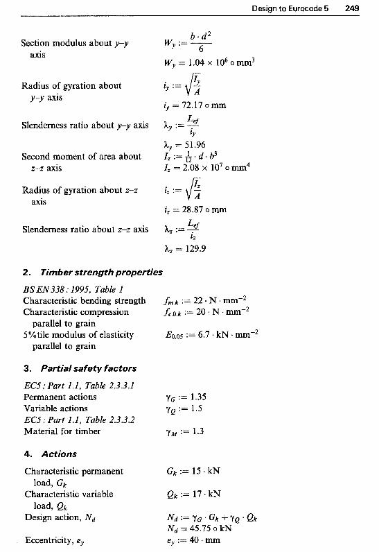
Design to Eurocode 5 249
b * d 2 Section modulus about y-y wy := - 6 axis
Wy = 1.04 x lo6 o mm3
Radius of gyration about l y 3 5 := y-y axis
iy = 72.17 o mm
Slenderness ratio about y-y axis hy := % IY
Ay = 51.96 Second moment of area about I, := h a d b3 z-z axis Iz = 2.08 x lo7 o mm4
- Radius of gyration about 2-2 l, := axis * v %
iz = 28.87 omm
Slenderness ratio about 2-2 axis h, := L;,f i z
h, = 129.9
2. Timber strength properties
BS EN 338 : 1995, Table l Characteristic bending strength fm.k := 22 N mmm2 Characteristic compression fc.o.k := 20 N
5%tile modulus of elasticity Eo.05 := 6.7 - k N .mm-2 parallel to grain
parallel to grain
3. Partial safety factors
EC5 : Part l .l, Table 2.3.3.1 Permanent actions := 1.35 Variable actions Y Q := 1.5 EC5 : Part l .l, Table 2.3.3.2 Material for timber yw := 1.3
4. Actions
Characteristic permanent G k := 15 kN
Characteristic variable Q k := 17 * kN
Design action, N d N d : = Y G ' G k + Y Q . Q k
Eccentricity, er ey := 40 mm
load, G k
load, Qk
N d = 45.75 o kN

250 Structural Timber Design
Design moment due to eccentricity about y-y axis
5. ~odifjcation factors
Factor for medium-duration loading and service class 1 (kmod, Table 3.1.7)
Load sharing does not apply (kis, Clause 5.4.6)
6. Bending strength
Design bending moment about
Design bending stress about y-y axis
y-y axis
No bending moment about z-z axis, thus
Design bending strength
7. Compression strength
Design compressive stress
Design compression strength
Buckling resistance (Clause 5.2.1, EC5):
Euler critical stresses about y-y and z-z axes
kt, :== 1.0
k i d = 1.83 o kN.m
0C.O.d = 1.83 o N - mm-2 kmod kls * fc.0.k
fc.0.d := Y M
fc.0.d = 12.31 o N. mm-2

Design to Eurocode 5 251
Relative slenderness ratios fc.0.k
0c.crit.y
5 e l . y =Z 0.9
Both relative slenderness ratios are > 0.5, hence conditions in Clause 5.2.1 (4) apply:
For a solid timber section, For a rectangular section
Thus (Clause 5.1.6),
and
Hence
and
Check the following conditions:
pc := 0.2 k m := 0.7
kc, := kY + J-h:,.
kc., = 0.81
kc. , := l
kc., = 0.18 0c.O.d 0m.z .d G m y d
kc., ‘fc.0.d fm.z.d fm.y.d +- +km” - 0.91
< 1.0 Satisfactory
< 1.0 Satisfactory
Therefore a l00 mm x 250 mm sawn section timber in strength class C22 is satisfactory
Example 70.3 Design of a timber-to-timber nailed tension splice joint
A timber-to-timber tension splice joint comprises two 47mm x 120mm inner members and two 33 mm x 120 mm side members of strength class C22 timber in service class 2. It is proposed to use 3.35 mm diameter, 65mm long round wire nails without pre- drilling. The joint is subjected to a permanent load of 2 kN and a medium-term variable load of 3 kN. Determine the required number of nails with a suitable nailing pattern.

Structural Timber Design
A Nailing zones
(a) Splice joint (Example 10.3).
Force, kN Length, m Cross-sectiQna1 dimensions, mm
eo~etr i~af prope~ies
Thickness of side members, tl Thickness of inner members, t2 Width of timber members, h Cross-sectional area of side
members, A, Cross-sectional area o f inner
members, Ai, Nail diameter, d Nail length, Inail Nail pointside penetration, tpoint
Clause 6.3.1.2, EC5 Minimum allowable pointside
For overlap nailing without penetration
pre-drilling
Stress, Nmmm2 N := newton kN := lo3 + N
tl := 33 .mm t2 := 47 mm h := 120 * mm
A, = 3.96 x lo3 o mm2 A, := h * tl
Ai, := h * t2 Ai, = 5.64 X lo3 o mm2 d := 3.35 - mm Inail := 65 + mm $point := haif - tl tpoint = 32 o mm
tpoint.adm := 8 d tpoint.ah = 26.8 o mm t2 - tpoht = 15 o mm > 4 d = 13.4 o,mm Both pointside penetration and overlap nailing are satisfactory
. ~ i ~ ~ ~ r s t r e ~ ~ t h properties
BS EN338 : 1995, Table I Characteristic tension parallel ft .0.k := 13 N mm-2
Characteristic density Pk := 340 * kg * m-3 to grain

Design to Eurocode 5 253
~ i a l safety factors
EC5 : Part 1.1, Table 2.3.3.1 Permanent actions YG := 1.35 Variable actions YQ := 1.5
EC5 : Part I J , Table 2,3,3.2 Material factor for timber yjl.l.timber := -3 Material factor for steel YM.steel := 1.1
Characteristic permanent load, G k G k := 2 kN Characteristic variable load, (& Q k := 3 + kN Design action, N d N d : = Y G ' G k S ' Y Q * e k
A. ~lt imate limit states N d = 7.2 o kN
difi~ation factors
Factor for medi~-durat ion kmod := 0.8 loading and service class 1 (kmod, Table 3.1.7)
Size factor ( k h , Clause 3.2.2) kh := 1.3 and k h := for h S50 mm is the lesser of:
k h == 1.05
. ~ e n ~ i o ~ strength of t i ~ b e r N d
2 * As Design tension stress parallel to cft.0.d := -
grain in side members cft.0.d = 0.91 o N mm-2
N d
A in Design tension stress parallel to cft.0.d := -
grain in inner members Dl.0.d = 1.28 o N mm-2
Design tension strength parallel ft .0.d := kmod kh 'ft.0.k
to grain YM.timber ft .0.d = 8.37 o N . mmw2 Tension strength satisfactory
7. ~ ~ ~ e d d i n g strength of timber
Characteristic embedding strength without pre-drilling
Since the following is an empirical equation (with hidden units in the coefficient part), for Mathcad to produce the correct units, multiply it by the units shown inside the parentheses; or alternatively use the equation without units for Pk and d. Thus:

254 Structural Timber Design
fh.k := 0.082 pk d-Ov3 * (sec-2 . m2-3 1.26 lo5) fh.k = 19.42 o N + mm-2
Design embedding strength kmod ' f h . k fh.1.d :=
for headside timber YM.timber
for pointside timber fh2.d Z"fh.1.d
fh.1.d = 11.95 o N mm-2
f h 2 . d = 11.95 0 N *
8. Yield moment of nails
Yield moment o f a nail (using a M y . k := 180 d2*6 . (kg. m-*6 s e c 2 n6.31 - io4) similar treatment for the units M y . k = 4.17 x lo3 o N mm as above)
Design yield moment kmod * M y . k
YM.stee1 1My.d :=
M y . d = 3.03 x lo3 o N mm
9. Load-carrying capacity
EC5, Clause 6.2.1 For a timber-to-timber joint with nails in single shear, design resistance per shear plane, R d , is the lesser of to R d f (see Table 10.6), where:
t 2 is the pointside penetration t2 := tpoint
and the ratio, P length
fh.1.d
P:=fh.2d p = 1
Failure mode (a) &.a :=fh. l .d * $ 1 * d
Failure mode (b) Rd.b :=fh. l .d t2 * d . P Rd.a = 1.32 X io3 0 N
Rd.b = 1.28 X lo3 0 N
Failure mode (c)
Failure mode (d)
Rd.c = 538.94 o N
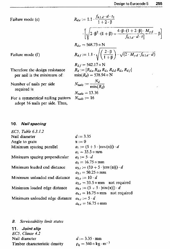
Design to Eurocode 5 255
Failure mode (e)
Failure mode (f)
R d . f = 542.17 0 N Therefore the design resistance R d := [Rd.a Rd.b Rd.c Rd.d Rd.e &.f]
per nail is the ~ n i m u m of: min(Rd) = 538.94 o N
Number o f nails per side required is
For a symmetrical nailing pattern Nnails := 16 adopt 16 nails per side. Thus,
l 0. NaiJ spacing
EC5, Table 6.3.1.2 Nail diameter Angle to grain Minimum spacing parallel
Minimum spacing perpendicular
Minimum loaded end distance
Minimum unloaded end distance
Minimum loaded edge distance
Minimum unloaded edge distance
d := 3.35 a := 0 a1 := ( 5 + 5 + lcos(a)l). d a1 = 33.5 o mm a2 := 5 . d a2 = 16.75 o mm
~ 3 , ~ = 50.25 o mm ~ 3 . ~ := 10 + d ~ 3 . ~ = 33.5 o mm not required ~ 4 . 1 := (5 + 5 lsin(a)l) d ~ 4 . ~ = 16.75 o mm not required ~ 4 . ~ := 5 d ~ 4 . ~ = 16.75 o mm
a3.t := (10 + 5 * ICOS ( c x ) ~ ) * d
B. Serviceability limit states
1 1 . Joint slip EC5, Clause 4.2 Nail diameter d := 3.35 mm Timber characteristic density pk = 340 o kg +
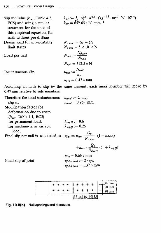
56 Structural Timber Design
Slip modulus (kser, Table 4.2, EC5) and using a similar treatment for the units of this empirical equation, for nails without pre-drilling
Design load for serviceability limit states
Load per nail
~nsta~taneous slip
Assuming all nails to slip by the 0.47mm relative to side members. Therefore the total instantaneous
slip is: ~ o d i ~ c a t i o n factor for
deformation due to creep ( k d d , Table 4.1, EC5) for ~ e ~ a n e n t load, for medium-term variable
load, Final slip per nail is calculated as
Final slip of joint
Uimt = 0.47 0 same amount, each inner member will move by
Fig. 10.9(b) Nail spacings and distances.

In the previous versions of BS 5268 : Part 2 the softwood timber section sizes were specified to BS4471: 1978 Spec~cation for sizes of sawn and processed softwood, which gave sizes and tolerances for three types of surface finish: sawn, planed and regularised. BS 5268 : Part 2 : 1996 requirements for timber target sizes are those given in BS EN 336 : 1995 Structural timber. Coniferous and poplar. Sizes. Permissible deviations and in its National Annex. This standard specifies two tolerance classes: tolerance class 1 (Tl) is applicable to sawn surfaces, and tolerance class 2 (T2) applicable to planed timber. Regularised timber can be achieved by specifying T1 for the thickness and T2 for the width.
The commonly available lengths and cross-section sizes are also listed in the National Annex of BS EN 336, and are referred to as target sizes. The target size is defined as the desired timber section size (at 20% moisture content) which can be used, without further modification, for design calculations.
Table A1 Basic sawn softwood timber section sizes whose sizes and tolerances comply with BS4471: 1978, at 20Y0 moisture content
Thickness Width (mm) (-1
75 100 125 150 175 200 225 250 300
36 38 44 47 50 63
75 100 150 200 250 300
X X
X X
X X
X X
X X
X
X
X
X X
X X
X X
X X
X X
X X
X X
X
X
X X
X X
X X
X X
X X
X X
X
X
X
X
X x x X x x X x x X
X x x x x
X
x X
257

258 Structural Timber Design
Table A2 Customary target sizes of sawn structural timber (Table NA.2, BS EN 336 : 1995)
Thickness Width (to tolerance class 1) (mm) (to tolerlance class 1) (mm) 75 100 125 150 175 200 225 250 275 300
22 25 38 47 63 75
100 150 250 300
X X X X
X X X X X
X X X X X
X X X X X
X X X X X X X X
X X
X
X
X
X
X X X
X
X X x x X X X
X
X
X
Note I Certain sizes may not be obtainable in the customary range of species and grades which
Note 2 BS EN 336 has a lower limit of 24 mm. However, as thinner material is used in the UK are generally available
the customary sizes of such material are also listed here
Table A3 Customary lengths of structural timber (Table NA. 1, BS EN 336 : 1995)
Length (m)
1.80 2.10 3.00 4.20 5.10 6.00 7.20 2.40 3.30 4.50 5.40 6.30 2.70 3.60 4.80 5.70 6.60
3.90 6.90
Note Lengths of 5.70m and over may not be readily available without finger jointing
In general, the differences between BS 4471 and BS EN 336 are minor and should not present any problems to specifiers and suppliers in the UK.' For comparison purposes, in Table A1 the basic sawn softwood timber section sizes whose sizes and tolerances comply with BS 4471 are given. The customary target sizes, whose sizes and tolerances comply with BS EN 336, for sawn strucural timber are given in Table A2. Table A3 gives the range of lengths of sawn softwood structural timber.
Reference
1. Fewell, A.R. (1997) Changes to the requirements and supply of timber structural materials, UKTEG Seminar, I. Struct. Eng., London, February.

Appendix B Weights of Building Materials
Some typical building material weights, for determination of dead loads, are tabulated in Table B 1. The values are based on BS 648 : 1964.
Table B1 Weights of building materials (based on BS 648 : 1964)
Material Unit mass
Asphalt Roofing 2 layers, 19mm thick Damp-proofing, 19 mm thick Bitumen roofing felts Mineral surfaced bitumen per layer Glass fibre Slab, per 25 mm thick Gypsum panels and partitions Building panels 75 mm thick Lead Sheet, 2.5mm thick Linoleum 3 mm thick Plaster Two coats gypsum, 13 mm thick Plastic sheeting Corrugated Plywood per mm thick Rendering or screeding Cement : sand (1 : 3), 13 mm thick Slate tiles (depending upon thickness and source) Steel Solid (mild) Corrugated roofing sheet per mm thick Tarmacadam 25mm thick Tiling Clay, for roof Timber Softwood Hardwood Water Woodwool Slab, 25mm thick
42 kg/m2 41 kg/m2
44 kg/m2
2-5 kg/m2
44 kg/m2
30 kg/m2
6 kg/m2
22 kg/m2
4.5 kg/m2
0.7 kg/m2
30 kg/m2
24-78 kg/m2
7850 kg/m3 10 kg/m2
60 kg/m2
70 kg/m2
590 kg/m3 1250 kg/m3 1000 kg/m3
15 kg/m2
259

itis t i
BS 52 Part 2 : 1996
Part 3 : 1998 Part 4 : 1978 Part 5 : 1989 Part 6 : S996 Part 7 : 1990
EC5
BS EN 384 : 1995
BS EN 385 : 1995
BS EN 518 : 1995
BS EN 336 : 1995
BS EN 338 : S995
BS EN519 : 1995
Structural use of timber Code of practice for permissible stress design, materials and workmanship. Code of practice for trussed rafter roofs. Fire resistance of timber structures. Preservation treatments for constructional timber. Code of practice for timber frame walls. Recommendations for the calculation basis for span tables.
DD EN77 1995-1-1 : 1994 E~rocode 5: structures General rules and rules for buildings (together with United Kingdom National Application Document)
Structural timber. Determination of characteristic values of mechanical properties and density.
Finger jointed structural timber. Performance requirements and minimum production requirements.
Structural timber. Grading. Requirements for visual strength grading standards.
Structural timber. Coniferous and poplar. Sizes. Permissible deviations.
Structural timber. Strength classes.
Structural timber. Grading. Requirements for machine strength graded timber and grading machines.
260

Related British Standards for Tmber Engineering 261
BS EN 301 : 1992 Adhesives, phenolic and aminoplastic, for load-bearing timber structures: classification and performance requirements.
BS EN 386 : 1995 Glued laminated timber. Performance requirements and minimum production requirements.
BS EN 390 : 1995 Glued laminated timber. Sizes. Permissible deviations.
BS EN 20898 Mechanical properties of fasteners.

This Page Intentionally Left Blank
actions, 221, 244, 249, 253 adhesives, 82, 195 additional properties, 18 axial compression, 56-63, 86, 89, 119, 148,
axial compressing and bending, 61-2, 68, 71,
axial loading, 56-81, 119, 151, 153
229
78, 122, 157, 230-31
basic stress, 10 beams
axes, 27, 225 circular, 29 curved, 90-92, 1 13-18 flitched, 38, 39 glued laminated, 26, 82-122, 225 notched, 36-7,46, 227-8 ply-webbed, 26, 123-42 rectangular, 26, 28-9 solid section, 26, 225 straight, 83 trimmer, 38, 39
deflection 33, 90, 129, 239-40 strength, 225-6 stress, 27-8, 61-2, 65, 86, 128, 157, 225-6
bending
bearing length, 35-6, 228-9 bearing stress, 34-6, 96, 101, 118, 228
boxed beams, 123 British grown timber, 14
bolts, 160, 163, 165, 179-88, 231, 235, 238
camber, 33, 83, 90, 239 cantilever, 239 ceiling tie, 204, 21 1 centre of geometry, 185 characteristic values, 220, 222 clear span, 28-9
columns, see Chapters 5, 6, 8 and 9 built-up, 143 combined stresses, 56, 61-2, 65, 230 effective length 57-8, 145-6, 230 glued laminated, 83, 119 load sharing, 63 permissible stresses, 60-62, 64-5, 86, 89,
rectangular solid, 56-64, 230, 231 slenderness ratio, 56-60, 145-6, 230-31 spaced, 143-58 spacer blocks, 144-8
146-7
combined stresses, 56, 61-2, 65, 230 computer, 2 1 compression, 56-64, 86, 89, 121, 147,228-31 concentric load, 60-61 connections, see Chapters 9 and 10
bolted, 163, 179-88, 231, 235, 238 dowelled, 163, 179-88, 231, 235, 238 glued, 195-6 nailed, 146, 163, 164, 166-75,231,235,238 nail-plates, 194 punched metal-plates, 160, 193-4 screwed, 146, 163, 165, 175-9, 238 shear-plates, 160, 163, 165, 191-3 split-rings, 160, 163, 165, 191-3 toothed-plates, 160, 163, 165, 189-90
conversion, 3, 4, 5, 8 creep, 220, 240, 241
decking, 37, 39 defects in timber, 3-5 deflection
bending, 33, 90, 129, 239-40 camber, 33, 83, 90, 239 cantilever, 239 creep, 220, 240, 241 final, 240-41
263

264 Index
deflection ( c o ~ ~ ~ ~ ~ e ~ ) instantaneous, 239-42 limits, 32, 239, 241 modification factor, 240 permissible, 32, 239, 241 shear, 34, 90, 129 slip in joints, 161-2, 241-2 slip modulus, 162, 241-2
depth to breadth ratio, 30 depth factor, 29, 87, 224 design philosophy
permissible stress, 10- 1 1 limit states, 11-12, 220
Douglas fir, 14, 164 dowels, 160, 163, 165, 179-88 dowelled joints, 163, 179-88, 231, 235, 238 durability, 195 duration of load, 11, 16-17, 127, 174, 179,
180-82
eccentric load, 61, 69, 248 effective cross-section, 162-3 effective geometrical properties, 124-5 effective length, 57-8, 145-6, 230 embedding strength
characteristic, 234-5 design, 234-5
end rotation, 226 European, 2 19 Eurocodes, 2 19 Eurocode 5, see Chapter 10
factor of safety, 221, 223 Finnish plywood, 133, 204, 216 flexural members, see Chapter 4, see also
beams floorboards, 37-9 form factor, 29
geometrical properties, 124-5 geometric centre, 185 glued joints
durability classification, 195 pressure, 196 strength, 195-6 stress, 196
glulam, see glued laminated glued laminated, see also Chapter 6
assembly, 82 bending deflection, 90 bending stress, 86, 89
column, 1 19 combined-grade, 84-5 curved beams, 90-92 horizontally laminated members, 84-7, 121 modification factors, 85-87 radial stress, 91-2 shear deflection, 90 single-grade, 84 vertically laminated members, 87-90, 120
grade stresses, 13, 15
hangers, joist, 39 Hankinson’s equation, 180, 185, 188 hardwoods, 5-6, 13, 15, 167 holes
bolts, 162, 179, 231 dowels, 179, 23 1 pre-drilled, 164, 167, 175
I-beams, 123, 124, 131, 137 imposed loads, 17 improved nails, 167, 174 instantaneous
deflection, 239-42 joint slip, 241-2
Johansen’s equations, 23 1 joinery joints, 159 joints, see Chapters 9 and 10, see also
bolted, 163, 179-88, 231, 235, 238 dowelled, 163, 179-88, 231, 235, 238 glued, 195-6 nailed, 146, 163, 164, 166-75,231,235,238 nail-plates, 194 punched metal-plates, 160, 193-4 screwed, 146, 163, 165, 175-9, 238 shear-plates, 160, 163, 165, 191-3 split-rings, 160, 163, 165, 191-3 toothed-plates, 160, 163, 165, 189-90
joists, 18, 37-9 hangers, 39 trimmer, 38, 39
connections
knots, 3
lateral support, restraint, 30-31, 131, 226 lateral stability, 30-3 1, 13 1 length, see effective length limit states, design philosophy, 11-12, 220

index 265
load duration, 11, 16-17, 127, 174, 179,
load sharing, 18, 63, 226 long-term loading, 17, 127, 174, 179, 180-82
180-82
224
machine stress grading, 12 Mathcad, see Chapter 3, 21-5 mechanical fasteners, see connections, joints medium-term loading, 17, 127, 174, 179,
metal-plate fasteners, 193-4 modulus of elasticity
minimum, 15, 58, 60 mean, 15, 87, 222 5th percentile, 222
180-82,224
moisture content, 6-7, 16, 224
nails, 160, 162, 231, 235, 237 nailed joints, 146, 163, 164, 166-75,231, 235,
National Application Document (NAD),
noggings, 62,63 notched beams, 36-7,46,227-8
panel shear, 127, 130 panel bending, 126 partial coefficients
for actions, 221 for material properties, 221, 223
permissible stresses solid section timber, 27, 28, 35, 36, 60, 61,
glued laminated, 86-7, 89, 92 plywood, 127, 128, 130, 131
ply-webbed beams, see Chapter 7 plywood
238
219, 226,240,241
62, 65
boarding, 39, 126 properties, 125, 127 permissible stresses, 127, 128, 130, 13 1
punched metal-plates, 160, 193-4
radial stress, 90-92 radius of gyration, 57 redwood, 14 rolling shear stress, 130-31
scarf joints, 159 screws, 160, 162, 231, 235
screwed joints, 146, 163, 165, 175-9, 238 second moment of area, 33, 57, 131 section size, 17, 30, 257 serviceclasses, 14-16, 127, 175, 179, 185, 190,
serviceability limit states, 12, 220, 239-42 shear deflection, 32, 34, 90, 129 shear modulus, 18, 129-30 shear-plate connectors, 160, 163, 165, 19 1-3 shear stress, 15, 19, 36-7, 86,89, 130-31, 161,
short-term loading, 16-17, 127, 174, 179,
Sitka spruce, 14 slenderness ratio, 56-60, 145-6, 230-3 1 slip, in joints, 161-2, 241-2 slip modulus, 162, 241-2 spaced columns, see Chapter 8 span, clear, design, effective, 28-9 species, 14 staples, 235 steel plates, gusset plates, 170, 174, 177, 184,
stiffeners, 13 1-2 strength classes, 13-15, 222 strength properties, 221-2
193, 223-4
227-8, 236
180-82, 224
189, 233, 235
studs, 62-3
tapered beams, 83, 98 tension members, 63-5, 229, 230 thickness, plywood, 125 tongued and grooved (t & g) floorboards, 38,
toothed-plate connectors, 160, 163, 165,
transformed section method, 124-5
ultimate limit states, 12, 220, 224-38
variable loads, actions, 221 very short-term loading, 17, 127
wane, 4, 5 web-stiffeners, 13 1-2 whitewood, 14 width factor, 64 wind loading, 17, 63, 224
yield moment
39
189-90
characteristic, 234-5 design, 234-5

This Page Intentionally Left Blank
m orksheet IS
All design examples given in this book are produced in the form of worksheets using Mathcad computer software and are available on 3 p' disks to run under Mathcad Version 6, or higher, in either one of its editions: Student, Standard, Plus or Professional. Mathcad runs under Windows Operating System on any IBM compatible Personal Computer.
The worksheet files are labelled exampm-n.mcd where m refers to the chapter number and n to the example number in that chapter. For example examp9-2.mcd refers to example 2 in Chapter 9.
It is recommended that the user makes a backup copy of the worksheets. This way he or she is free to experiment with the files. When a worksheet is loaded it should be saved under a new name so that when modified the original disk file is not altered.
Although every care has been taken to ensure the accuracy of the example worksheets, it remains the responsibility of the user to check their results.
Please copy and complete the form at the back of the book, enclosing a cheque or postal order for E20 which includes handling and postage and packing, made payable to A. Kermani, and send to:
A. Kermani, 4 Mid Steil, Glenlockhart, Edinburgh EH10 5XB, 1JK email: [email protected]
267
268 Structural Timber Design
Structural Timber Design Mathcad Worksheets
Name: Title:
Please indicate your profession
Architect U Building control officer Building engineer U Civillstructural engineer Educator U Student U
Address:
Postcode:
Date:
Note: There is no warranty with the worksheets.